Article

Broadband-Transmissive, Frequency-Selective Rasorber Design Using Characteristic Mode Analysis

1
College of Physics Science and Technology, Central China Normal University, Wuhan 430079, China
2
School of Physics and Telecommunications, Huanggang Normal University, Huanggang 438000, China
3
Wuhan Cigarette Factory, China Tobacco Hubei Industrial Co., Ltd., Wuhan 430032, China
4
Institute of Space Science and Technology, Nanchang University, Nanchang 330021, China
*
Authors to whom correspondence should be addressed.
Electronics 2022, 11(9), 1418; https://doi.org/10.3390/electronics11091418
Submission received: 23 March 2022 / Revised: 21 April 2022 / Accepted: 26 April 2022 / Published: 28 April 2022
(This article belongs to the Special Issue Metasurfaces Applications in Antennas and Microwave Devices)

Abstract

:
This article designs a frequency-selective rasorber (FSR) with a broadband transmission window. It is synthesized by a broadband absorber and a frequency-selective surface (FSS). The resistive layer achieves broadband absorption by introducing a tortuous Jerusalem cross load with lumped resistors, and the lossless FSS adopts a three-layer metal structure to realize the broadband transmission window. The absorption mechanism of the resistive layer is analyzed using the theory of characteristic mode. The position of the resistor is determined according to the analysis of mode current distribution and parameter optimization. Prototypes of the structure were fabricated and measured, and the simulation results show that the 1 dB transmission window and the absorption band with | S 11 | < −1 dB are 36.4% and 97%, respectively. Therefore, the designed FSR has potential application prospects in electromagnetic stealth technology and radar cross-section reduction.

1. Introduction

With the development of electromagnetic metamaterials, frequency-selective surfaces (FSSs) have attracted much attention [1,2,3]. The FSS radomes are capable of reflecting out-of-band energy while ensuring the communication window within the operation band. However, the reflected out-of-band signal can be ineffective for bistatic or multistatic radar cross-section (RCS) reduction. In order to solve this imperfection, a frequency-selective rasorber (FSR) with a transmission/absorption window was proposed [4]. FSR is generally used for reducing RCS by absorbing out-of-band energy instead of reflecting it.
In recent decades, some FSRs have been widely proposed and published [5,6,7,8,9,10]. Existing FSRs can generally be classified into three categories based on the relative positions of the transmission window and absorption bands: (1) the transmission window below an absorption band (TA-FSR) [5,6], (2) the transmission window above the absorption band (AT-FSR) [7,8], and (3) the transmission window within the absorption bands (ATA-FSR) [9,10]. However, in the previous literature, a common feature of FSRs is that they are narrow transmission windows. For some practical applications, for example, the stealth radome of the broadband antenna systems, the broadband transmission property is crucial. The transmission band of the FSR directly affects the radiation performance of the antenna system. There are many methods to achieve the broadband transmission of the FSR [11,12,13,14,15,16,17,18,19]. For instance, in [11], the researchers achieved a broadband transmission window by using lossless resonators in parallel wave guides with a metal post in the center. In [12], the broadband transmission is achieved by two layers of patches coupled through an aperture-coupling layer. However, in the above-mentioned literature, the maximum value of the 1 dB transmission band is less than 33.5%. Moreover, ref. [18] adopts an array of the cascaded square patches with two types of modified slot structures in the middle layer to realize three transmission poles to obtain broadband characteristics. Unfortunately, it achieves broadband transmission but does not absorb EM. Some recent work on Jerusalem-cross-based FSS has been published [20,21,22,23]. However, it only has narrow pass and stop bands, in addition to the 2D FSR. Several 3D FSRs have been proposed to achieve transmission and absorption [24,25]. In [25], a low-profile 3D FSR with two-sided, wide absorption bands was proposed utilizing a wideband magnetic material and a 3D FSS. However, due to the complexity and higher cost of fabrication, its application is limited.
The equivalent circuit method (ECM) has been widely used to analyze the design of absorption structures [9,16]. However, the ECM has some limitations for complex structures. Some advanced theories in computational electromagnetics can be used to guide the design of absorbing structures. In 1965, Dr. Garbacz first proposed the theory of characteristic mode (TCM) [26]. The TCM is a complete set of orthogonal modes for expanding any induced currents and far-field characteristics due to external sources. With the development of TCM, it has been widely used in various antenna designs [27,28]. Recently, some researchers have begun to use the TCM to analyze the absorbers [29,30,31,32].
This paper proposed an FSR with a broadband transmission and low insertion loss (IL). The absorption mechanism of FSR is analyzed utilizing TCM. Moreover, the position and the value of the lumped resistors are decided according to the analysis of the mode current and parameter optimization. The broadband transmission window is achieved by a three-layer metal structure, in which two layers of cascaded square plate resonators are coupled through three rotating C-type apertures in the middle. Finally, the designed FSR has a 1 dB transmission window between 9.3 GHz and 13.45 GHz, corresponding to the FBW of 36.4%, and a one-sided absorption bandwidth of 97%.

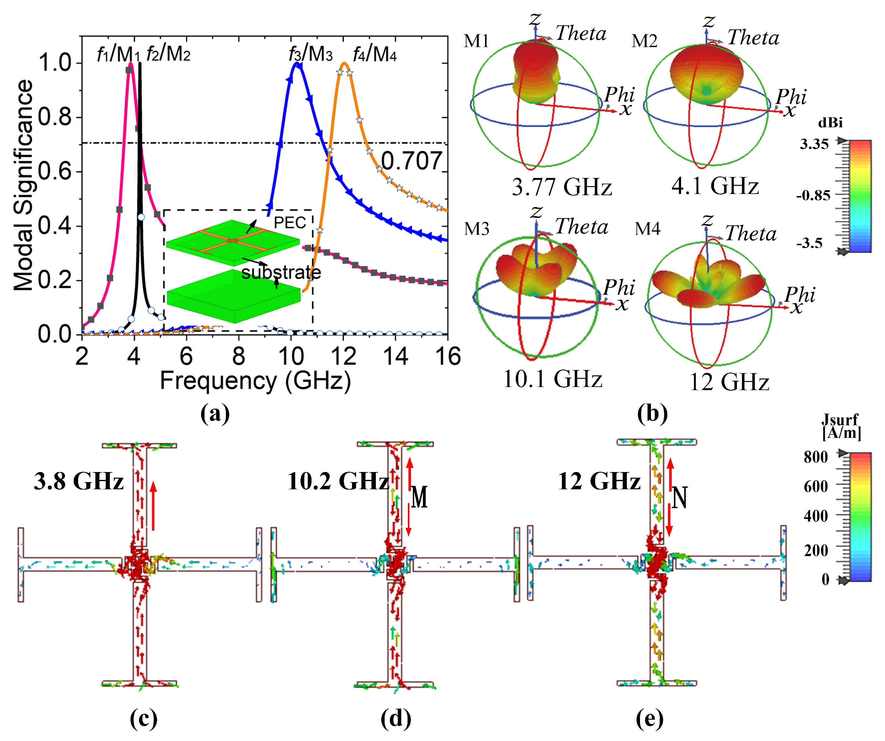
2. Theory of Characteristic Mode

The theory of characteristic mode can be utilized to perfect electrical conductors, dielectrics and magnetic materials [30]. In general, there are two important evaluation parameters that are often used to judge whether a certain characteristic mode can be effectively excited in the analysis of eigenmode theory, namely, eigenvalue and mode significance (MS).
(1) Eigenvalue:
According to the TCM, the total distribution of currents is regarded as the modal weighting coefficients ( α n ) and the mode current ( J n ):
α n = E i ( r ) , J n 1 + j J n
J = n α n J n
where λ n stands for the eigenvalue of mode current ( α n ), E i is called the impressed electric field, and the inner product, E i ( r ) , J n , represents the modal excitation coefficient when the external excitation source is coupled with each characteristic mode.
(2) Modal Significance (MS):
MS is an inherent feature of each characteristic mode, to a certain extent. It shows the degree of excitation of each mode in the external excitation sources. The MS can be defined as:
M S = | 1 1 + j J n |
When MS = 1, i.e., | λ n |   =   0 , shows that the model can be effective incentive near its resonant frequency. In the actual simulation analysis, MS > 0.707 can be considered as the resonant mode.
For the absorption structure, the impressed electric field ( E i ) induces mode currents J on the perfect electric conductor (PEC) metallic structure of unit cells. The mode current will motivate a scattered field, which can be analyzed and directed to the design of the absorber by observing the scattered field and mode current. Therefore, we use the TCM to guide the design of the absorption structure.

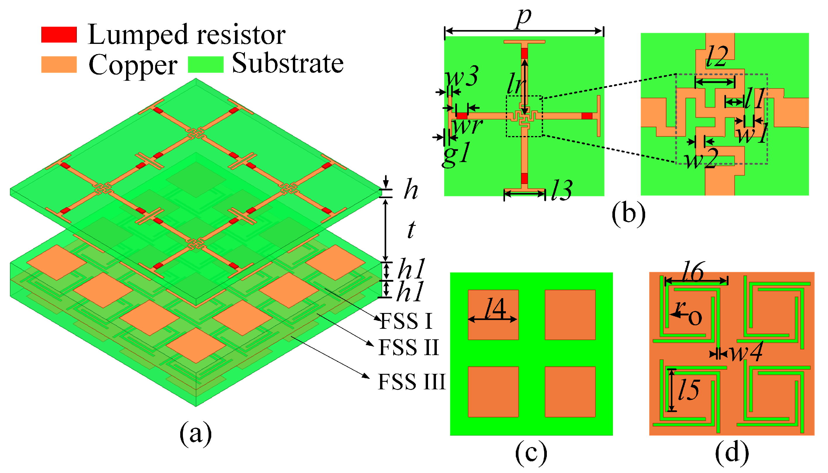
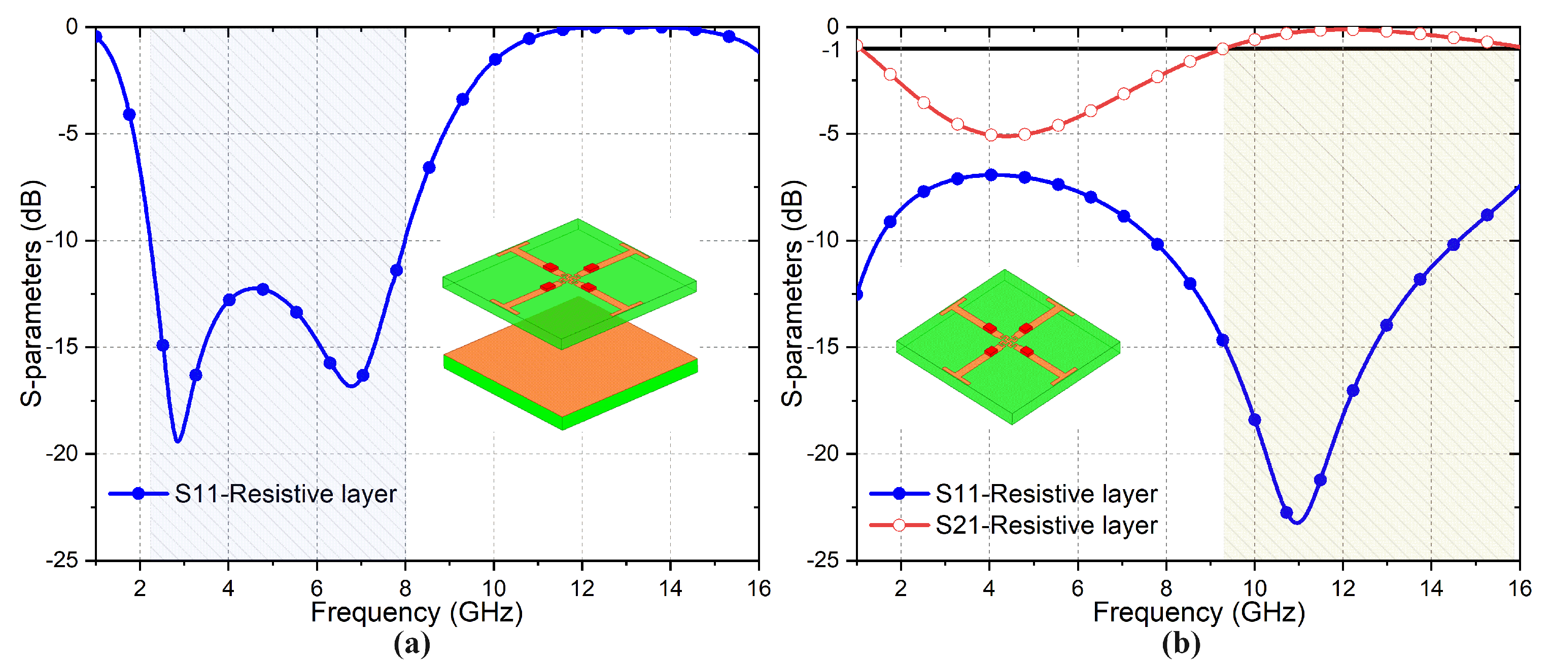
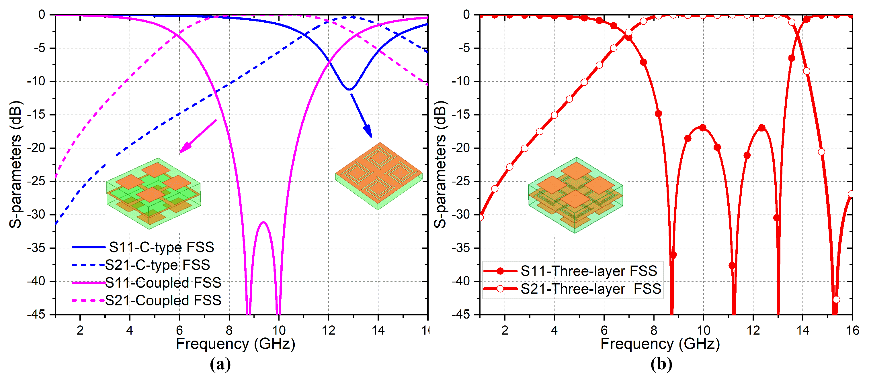
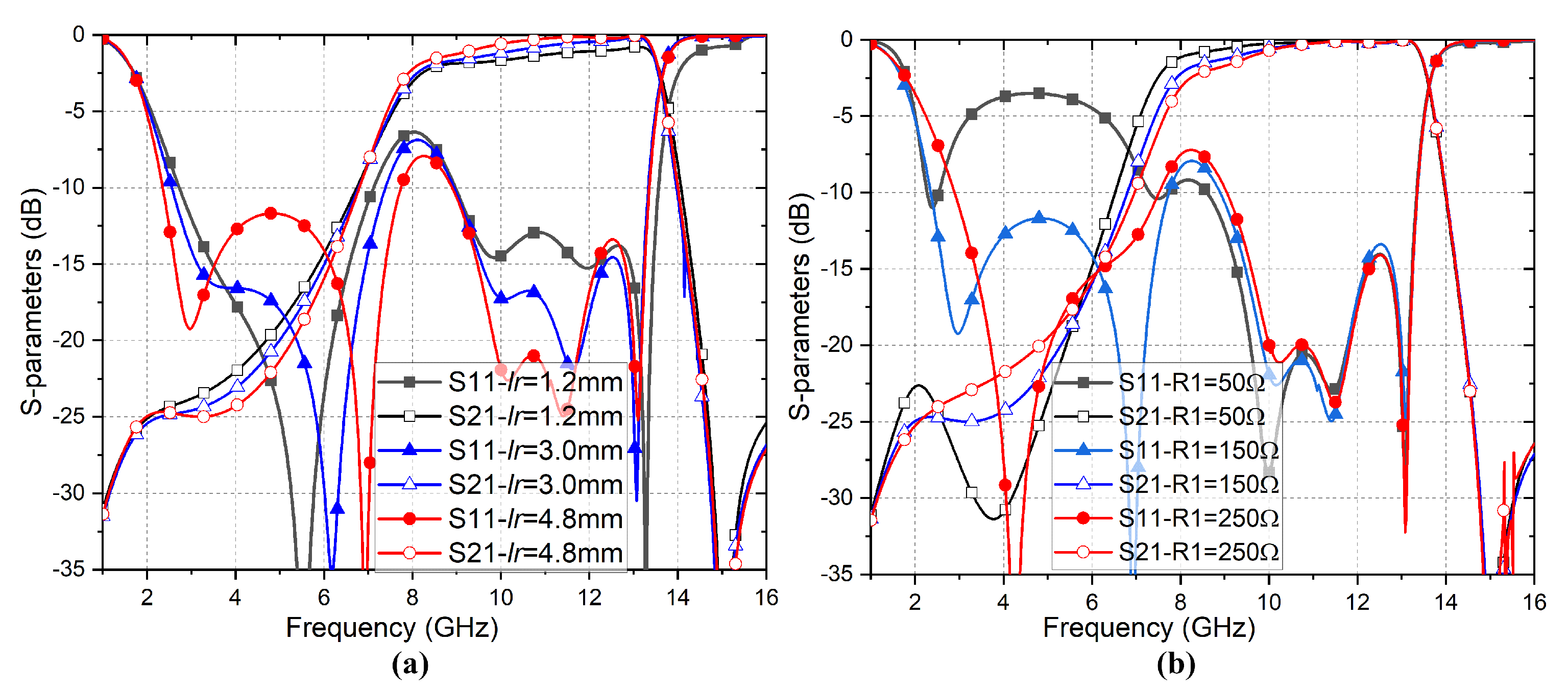
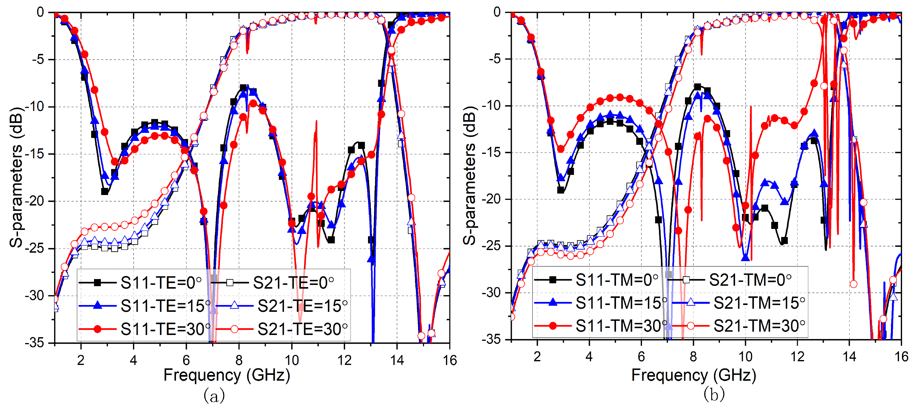
3. Design and Analysis of the FSR

Figure 1 demonstrates the profile sketch of the proposed FSR. According to the figure, we can conclude that the FSR consists of a resistive layer and a three-layer bandpass FSS structure. The two parts of the structure are separated by air. As shown in Figure 1b, the resistive layer achieves broadband absorption by introducing a tortuous Jerusalem cross, loaded with lumped resistors. Four lumped resistors are loaded to the appropriate location and their resistance value is 150 Ω . The resistive layer is printed on a 0.813 mm-thick Rogers 4003C. The relative permittivity and the loss tangent of the dielectric substrate are 3.38 and 0.0027, respectively. As illustrated in Figure 1c,d, the bandpass structural unit is coupled with two layers of cascaded square-plate resonators and three rotating C-type apertures in the middle. The relative permittivity of the bandpass substrate layer is ε r = 3, the loss tangent is μ r =1 and the thickness is 2 mm.
To investigate the radiating character of the designed FSR from a physical mechanism, the theory of characteristic mode is introduced to analyze the structure of the resistive layer. The radiation patterns and mode currents are simulated by applying moments-based TCM. Figure 2a shows the mode significance (MS) of the tortuous Jerusalem cross. Within 1–16 GHz, there are four modal resonances whose MS are greater than 0.707 at 3.77 GHz, 4.1 GHz, 10.1 GHz, and 12 GHz, respectively. However, since the bandwidths of MS > 0.707 are not broad at these frequencies, the top structure only owns a narrow absorption band. Figure 2b shows four modal fields of tortuous Jerusalem cross. It illustrates that, since the main lobes of M1 and M2 are perpendicular to the unit cell, the first mode and the second mode are effective modes under normal incidence. M3 and M4 have weak fields in the Z direction and are not effective modes.
As shown in Figure 2c–e, we also concentrate on the mode current at the resonant frequencies. At 3.8 GHz, the strong current flows to the top of the Jerusalem intersection along the tortuous line, as shown by the red arrow. Moreover, we analyze the mode current at the frequency points of 10.2 GHz and 12 GHz. It can be observed from Figure 2d,e that the direction of current flow was changed at points M and N. It is shown that the resistive layer structure not only generates strong resonance at three frequency points but also affects different ranges of resonance.
However, the bandwidth of MS > 0.707 is narrow. To enlarge the absorption bandwidth, the loss elements (such as lumped resistors) are loaded at metal locations with strong currents. After loading the lumped resistors, the MS of the absorption structure is shown in Figure 3a. It exhibited that the bandwidth of all modes has been broadened. As the resistance increases, the bandwidth will broaden accordingly. It can be seen from Figure 3b that M1 and M2 are effective modes. Therefore, we obtained a bandwidth with MS > 0.707 ranging from 1.9 GHz to 7.3 GHz. By observing the mode current distribution, it is obvious that the mode current of the structure is weak and the energy is absorbed by the resistors. Similarly, we analyze the mode current at 10.2 GHz and 12 GHz. Unlike the current distribution at low frequencies, the mode current is still strong when the resistors are added at 10.2 GHz and 12 GHz, as shown in Figure 3d,e. On the other hand, we can also see that the current changes direction at the point N at 12 GHz, while the current does not change at the point M at 10 GHz. It implies that the addition of resistors at 10 GHz has a greater effect than at 12 GHz.
Finally, we obtain the absorption performance shown in Figure 4a. The resistive layer has a good absorption effect in the range of 2.1 GHz–8.0 GHz. Based on the above analysis of characteristic mode and mode current, it is found that the resistive layer resonances at frequency points 10.2 GHz and 12 GHz. In order to better explore the characteristics of these two resonance points, we studied the transmission/reflection coefficient of a resistive layer without a ground layer, as shown in Figure 4b. As observed, the resistive layer has a broadband transmission window ranging from 9.3 GHz to 15.9 GHz. Therefore, we can replace the metal ground in the absorption layer with a transmission structure to realize an FSR with absorption and transmission functions.
In the bandpass FSS layer, we first designed a single-layer C-slot structure, as given in Figure 5a. It is found that the 1 dB transmission bandwidth of the C-type FSS spans from 11.7 GHz to 13.46 GHz. Then, a cascaded square-patch resonator with an aperture-coupled FSS layer was designed to implement the broadband bandpass FSS. It can be shown that the insertion loss over 7.1–12 GHz is less than 1 dB. To further broaden the passband bandwidth, the C-type structure and the coupled FSS structure are combined into the three-layer FSS. The frequency response of the three-layer FSS is depicted in Figure 5b. As observed, the 1 dB transmission window ranges from 7.56 GHz to 13.46 GHz with the FBW of 56.1%. Obviously, the proposed three-layer FSS structure achieves a wider transmission bandwidth.
Next, the broadband FSS and resistance layer are integrated to form an FSR with a broadband transmission window, in order to analyze the effects of varied geometric and material parameters on FSR performance. The resistance value (R1) of the lumped resistor and the position (lr) of resistors are two key parameters that dominate frequency response performance of the FSR. Figure 6 is given to demonstrate the variation trend of the absorption and transmission performance of the proposed FSR with different lr and R1. As shown in Figure 6a, the IL at the transmission window of the designed FSR is mostly influenced by lr. According to the previous TCM analysis, the closer the resistance is to the tortuous structure, the better the absorption effect. Unfortunately, the position of the resistors can cause a serious impact on the IL at the passband. As can be seen in Figure 6a, when lr increases from 1.2 mm to 4.8 mm, the 1 dB transmission window increases from 9.3% to 36.4%. Figure 6b illustrates the absorption efficiency of the proposed FSR is controlled by the value of the lumped resistors. A large or small lumped resistor will lead to poor absorption band performance. After simulation and comparison of several parameters, the absorbing band and 1 dB transmission band are integrated, lr is 4.8 mm and the resistance R1 is optimized to be 150 Ω to obtain the best absorption/transmission performance.
Figure 7 shows the frequency response of the proposed FSR for both TE and TM polarizations under different incident angles.The absorption performance of the proposed FSR becomes narrowed with the increase in incident angle under TE polarization, whereas under TM polarization, the absorption performance becomes deteriorated. The reason for this phenomenon is that the impedance of the incident EM is different under various polarizations. As the incident angle increases, the impedance mismatch increases, which leads to the absorption performance of the structure decreasing. Overall, the proposed structure can ensure its angle stability in the case of oblique incidence of 30 . The main reason for the disturbance at passband under two polarization is that the design size of the top structure is too large, so grating lobes are generated at higher frequencies. The disturbance at higher frequency in Figure 7 is mainly caused by the top-layer structure, because the top structure is four times the size of the FSS layer.

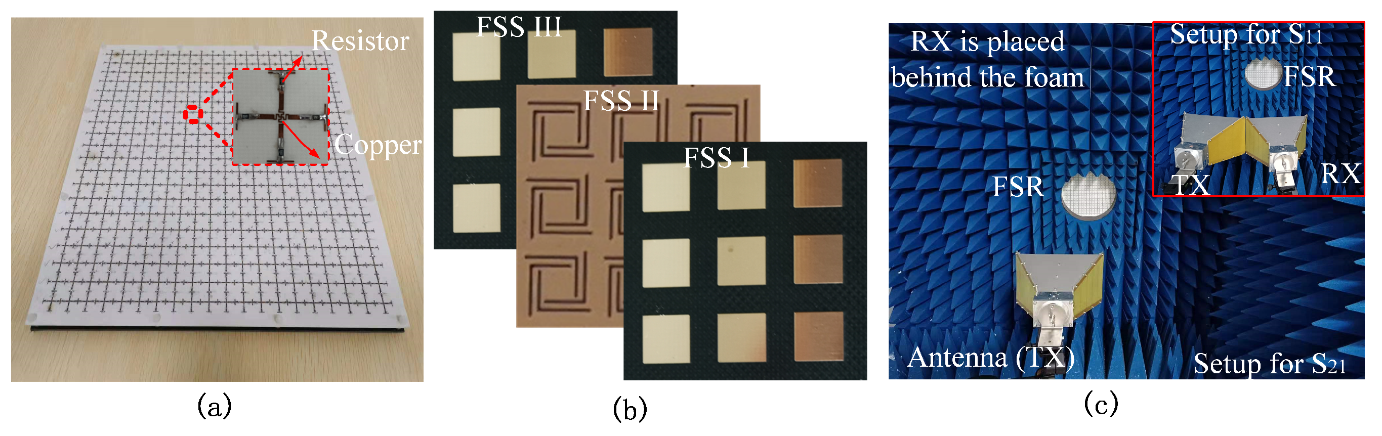
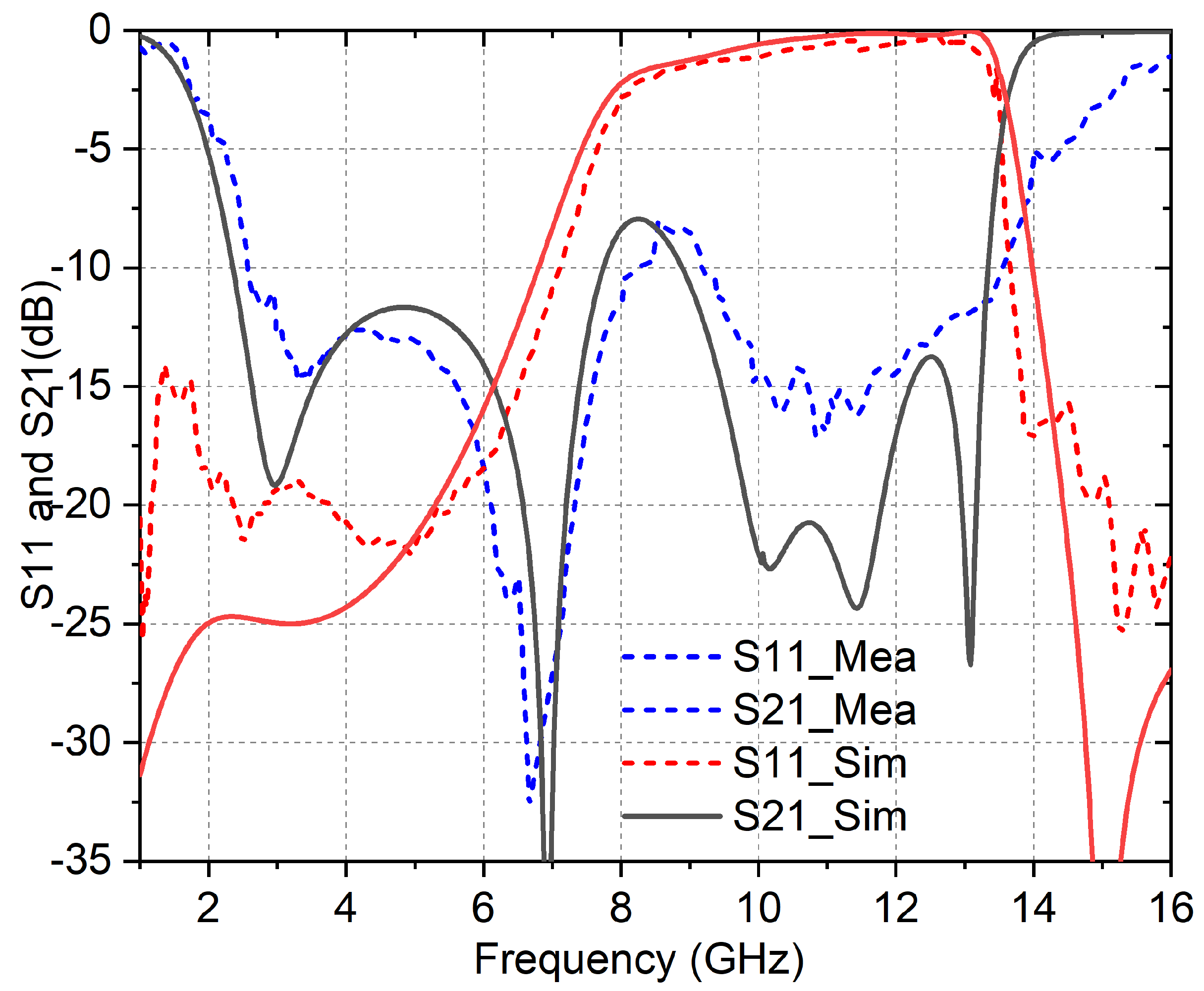
4. Experimental Verification

To further demonstrate the validity of the reflection and transmission performance of the proposed FSR, a prototype of the proposed FSR was fabricated and measured, as shown in Figure 8. The overall size of the assembled prototype is 300 × 300 × 13.8 mm 3 with 20 × 20-unit cells. The resistive layers are processed on 0.813 mm-thick Rogers 4003C. For each element, four resistors of 150 Ω with 0603 package are welded on Jerusalem structural metal strips. Similarly, for the broadband transmission layer, its periodic pattern of the top layer and the intermediate layer is printed on either side of a 2 mm-thick Teflon substrate, respectively. The bottom patch pattern is processed on another 2 mm-thick substrate. Plastic nylon screws were fixed around the sample to achieve a spacing of 9 mm between the resistive layers and the broadband transmission layers.
The reflection and transmission coefficients of the fabricated prototype were measured using the free space measurement method. The setup consists of two standard horn antennas and a network analyzer (Agilent N5230A). Two horn antennas are placed on both sides of the FSR sample when measuring the transmission coefficient, and two horn antennas are side by side toward the FSR sample while measuring the reflection coefficient. Figure 9 shows the measured and simulation results under normal incidence. It is observed that there is a good agreement between the simulation and experimental results. However, there is a slight frequency shift occurring between them, mainly due to unavoidable measurement tolerances and limitations on the electrical dimensions of the prototype.
To verify the preponderance of the proposed FSR, a performance comparison between our proposed FSR with other published FSRs is tabulated in Table 1. It can be seen from the comparison that the proposed FSR has the advantages in both transmission window and absorption bandwidth.

5. Conclusions

In this article, we designed and fabricated a frequency-selective rasorber (FSR) with broadband transmission window. The TCM was used to guide the design of the resistive layer with tortuous Jerusalem cross, and the MS > 0.707 determines the range of absorption band. The position of the lumped resistor is determined by mode current distribution and parameter optimization. Moreover, the FSS with broadband transmission window is realized in a high-frequency band by synthesizing the single-layer C-slot structure and the cascaded square patch resonator with hole-coupled FSS layers. The FBW of its 1 dB transmission band and 10 dB absorption window reaches 36.4% and 97%, respectively. At the same time, due to its small periodicity and rotational symmetry, the proposed FSR also exhibits good features under the polarization and incident angles. The proposed FSR can potentially be applied to design stealth radomes for applications from communication to broadband antennas.

Author Contributions

H.L. and J.X. conceived and designed the experiments; B.Y. and Y.W. designed the simulations; Y.W. and Q.L. analyzed the data; X.Z. contributed analysis tools; H.L. and R.T. revised the paper. All authors have read and agreed to the published version of the manuscript.

Funding

This research was funded by the Fundamental Research Funds for the Central University of China under Grant Nos.CCNU20GF004 and CCNU19TS073, the open fund of Guangxi Key Laboratory of Wireless Wideband Communication and Signal Processing under Grant No.GXKL06190202, the open fund of China Ship Development and Design Center under Grant No.XM0120190196 and the National Natural Science Foundation of China under Grant No.41974195. This work is partly supported by the Hongque Innovation Center under Grant HQ202104001.

Data Availability Statement

The data presented in this study are available in article.

Conflicts of Interest

The authors declare no conflict of interest.

References

  1. Can, S.; Karakaya, E.U.; Ylmaz, A.E. Design, fabrication, and measurement of textile-based frequency selective surfaces. Microw. Opt. Technol. Lett. 2020, 62, 3444–3450. [Google Scholar] [CrossRef]
  2. Fahad, A.K.; Ruan, C.; Nazir, R.; Haq, T.U.; He, W. Dual-Band Ultrathin Meta-Array for Polarization Conversion in Ku/Ka-Band With Broadband Transmission. IEEE Antennas Wirel. Propag. Lett. 2020, 19, 856–860. [Google Scholar] [CrossRef]
  3. Omar, A.A.; Kim, J.; Hong, W. A 3-D Lumped-Components-Free Absorptive Frequency-Selective Transmission Structure Featuring Very Wide Two-Sided Absorption Bandwidths. IEEE Antennas Wirel. Propag. Lett. 2020, 19, 761–765. [Google Scholar] [CrossRef]
  4. Costa, F.; Monorchio, A. A Frequency Selective Radome With Wideband Absorbing Properties. IEEE Trans. Antennas Propag. 2012, 60, 2740–2747. [Google Scholar] [CrossRef]
  5. Bakshi, S.C.; Mitra, D.; Ghosh, S. A Frequency Selective Surface Based Reconfigurable Rasorber With Switchable Transmission/Reflection Band. IEEE Antennas Wirel. Propag. Lett. 2019, 18, 29–33. [Google Scholar] [CrossRef]
  6. Sheng, X.; Gao, X.; Liu, N. Design of frequency selective rasorber with high in-band transmission and wideband absorption properties. IEICE Electron. Express 2019, 16, 20190545. [Google Scholar] [CrossRef] [Green Version]
  7. Yu, S.; Kou, N.; Ding, Z.; Zhang, Z. Harmonic-Suppressed Frequency Selective Rasorber Using Resistive-Film Sheet and Square-Loops Resonator. IEEE Antennas Wirel. Propag. Lett. 2020, 19, 292–296. [Google Scholar] [CrossRef]
  8. Chen, Q.; Guo, M.; Sun, Z.; Sang, D.; Fu, Y. Polarization-independent frequency-selective rasorber with a broadened absorption band. Aeu Int. J. Electron. Commun. 2018, 96, 178–183. [Google Scholar] [CrossRef]
  9. Guo, Q.; Su, J.; Li, Z.; Yang, L.Y.; Song, J. Absorptive/Transmissive Frequency Selective Surface With Wide Absorption Band. IEEE Access 2019, 7, 92314–92321. [Google Scholar] [CrossRef]
  10. Sharma, A.; Ghosh, S.; Srivastava, K.V. A polarization-insensitive band-notched absorber for Radar Cross Section reduction. IEEE Antennas Wirel. Propag. Lett. 2020, 20, 259–263. [Google Scholar] [CrossRef]
  11. Shen, Z.; Jiang, W.; Bo, L. 3-D Frequency Selective Rasorber: Concept, Analysis, and Design. IEEE Trans. Microw. Theory Tech. 2016, 64, 3087–3096. [Google Scholar] [CrossRef]
  12. Jin, C.; Lv, Q.; Wang, J.; Li, Y. Capped Dielectric Inserted Perforated Metallic Plate Bandpass Frequency Selective Surface. IEEE Trans. Antennas Propag. 2017, 65, 7129–7136. [Google Scholar] [CrossRef]
  13. Chen, Q.; Sang, D.; Guo, M.; Fu, Y. Miniaturized Frequency-Selective Rasorber With a Wide Transmission Band Using Circular Spiral Resonator. IEEE Trans. Antennas Propag. 2019, 67, 1045–1052. [Google Scholar] [CrossRef]
  14. Wang, Z.; Fu, J.; Zeng, Q.; Song, M.; Denidni, T.A. Wideband Transmissive Frequency-Selective Absorber. IEEE Antennas Wirel. Propag. Lett. 2019, 18, 1443–1447. [Google Scholar] [CrossRef]
  15. Guo, M.; Chen, Q.; Bai, T.; Wei, K.; Fu, Y. Wide Transmission Band Frequency-Selective Rasorber Based on Convoluted Resonator. IEEE Antennas Wirel. Propag. Lett. 2020, 19, 846–850. [Google Scholar] [CrossRef]
  16. Sheng, X.; Gao, X.; Liu, N. Design of frequency selective rasorber with wide transmission/absorption bands. J. Phys. D Appl. Phys. 2020, 53, 1–6. [Google Scholar] [CrossRef]
  17. Yang, Z.; Jiang, W.; Huang, Q.; Hong, T. A 2.5-D Miniaturized Frequency-Selective Rasorber With a Wide High-Transmission Passband. IEEE Antennas Wirel. Propag. Lett. 2021, 20, 1140–1144. [Google Scholar] [CrossRef]
  18. Lv, Q.; Jin, C.; Zhang, B.; Mittra, R. Wide-Passband Dual-Polarized Elliptic Frequency Selective Surface. IEEE Access 2019, 7, 55833–55840. [Google Scholar] [CrossRef]
  19. Lin, H.; Wu, Y.; Xiong, J.; Zhou, R.; Li, Q.; Tang, R. Dual-polarized bidirectional three-dimensional metamaterial absorber with transmission windows. Opt. Express 2021, 29, 40770–40780. [Google Scholar] [CrossRef]
  20. Zahra, H.; Abbas, S.M.; Hashmi, R.M.; Esselle, K.P. Switchable Frequency Selective Surface Based on Composite Flexible Substrate for Modern Communication Systems. In Proceedings of the URSI Asia-Pacific Radio Science Conference (AP-RASC 2019), Delhi, India, 9–15 March 2019; pp. 1–2. [Google Scholar]
  21. Zahra, H.; Abbas, S.M.; Hashmi, R.M.; Matekovits, L.; Esselle, K.P. Bending analysis of switchable frequency selective surface based on flexible composite substrate. In Proceedings of the 2019 IEEE International Symposium on Antennas and Propagation and USNC-URSI Radio Science Meeting, Atlanta, GA, USA, 7–12 July 2019; pp. 2033–2034. [Google Scholar] [CrossRef]
  22. Zahra, H.; Abbas, S.M.; Shafique, M.F.; Esselle, K.P. A switchable FSS based on modified Jerusalem-cross unit cell with extended top loading. In Proceedings of the 2015 International Symposium on Antennas and Propagation (ISAP), Hobart, TAS, Australia, 9–12 November 2015; pp. 1–2. [Google Scholar]
  23. Zahra, H.; Rafique, S.; Shafique, M.F.; Esselle, K.P. A switchable frequency selective surface based on a modified Jerusalem-cross unit cell. In Proceedings of the 2015 9th European Conference on Antennas and Propagation (EuCAP), Lisbon, Portugal, 13–17 April 2015; pp. 1–2. [Google Scholar]
  24. Omar, A.A.; Huang, H.; Shen, Z. Absorptive frequency-selective reflection/transmission structures: A review and future perspectives. IEEE Antennas Propag. Mag. 2019, 62, 62–74. [Google Scholar] [CrossRef]
  25. Wang, Y.; Wang, M.; Shen, Z.; Wu, W. 3-D Single-and Dual-Polarized Frequency-Selective Rasorbers With Wide Absorption Bands Based on Stepped Impedance Resonator. IEEE Access 2021, 9, 22317–22327. [Google Scholar] [CrossRef]
  26. Garbacz, R.J. Modal expansions for resonance scattering phenomena. Proc. IEEE 1965, 53, 856–864. [Google Scholar] [CrossRef]
  27. Lin, F.H.; Chen, Z.N. Low-Profile Wideband Metasurface Antennas Using Characteristic Mode Analysis. IEEE Trans. Antennas Propag. 2017, 65, 1706–1713. [Google Scholar] [CrossRef]
  28. Gao, G.; Zhang, R.; Geng, W.; Meng, H.; Hu, B. Characteristic Mode Analysis of a Nonuniform Metasurface Antenna for Wearable Applications. IEEE Antennas Wirel. Propag. Lett. 2020, 19, 1355–1359. [Google Scholar] [CrossRef]
  29. Song, Z.; Zhu, J.; Yang, L.; Min, P.; Lin, F.H. Wideband metasurface absorber (metabsorber) using characteristic mode analysis. Opt. Express 2021, 29, 35387–35399. [Google Scholar] [CrossRef]
  30. Wu, Y.; Lin, H.; Xiong, J.; Hou, J.; Zhou, R.; Deng, F.; Tang, R. A broadband metamaterial absorber design using characteristic modes analysis. J. Appl. Phys. 2021, 129, 134902–134928. [Google Scholar] [CrossRef]
  31. Guo, Q.; Su, J.; Li, Z.; Song, J.; Guan, Y. Miniaturized-Element Frequency-Selective Rasorber Design Using Characteristic Modes Analysis. IEEE Trans. Antennas Propag. 2020, 68, 6683–6694. [Google Scholar] [CrossRef]
  32. Guo, Q.; Su, J.; Li, Z. Design of circuit analog absorber using characteristic mode analysis. In Proceedings of the 2020 IEEE MTT-S International Microwave Workshop Series on Advanced Materials and Processes for RF and THz Applications (IMWS-AMP), Suzhou, China, 29–31 July 2020; pp. 1–3. [Google Scholar] [CrossRef]
  33. Jiao, W.H.; Chang, Y.M.; Wang, L.; Wu, W.J. A Dual-Polarized Frequency Selective Rasorber with Wide Transmission Band. Radio Sci. 2021, 56, 7129–7136. [Google Scholar] [CrossRef]
  34. Xiu, X.; Che, W.; Han, Y.; Yang, W. Low-Profile Dual-Polarization Frequency Selective Rasorbers Based on Simple-Structure Lossy Cross-Frame Elements. IEEE Antennas Wirel. Propag. Lett. 2018, 1002–1005. [Google Scholar] [CrossRef]
  35. Wang, X.; Wang, J.; Yan, M.; Yang, J.; Qu, S. A Frequency Selective Rasorber by Engineering Transverse Standing Waves of Surface Current. IEEE Access 2021, 9, 51703–51709. [Google Scholar] [CrossRef]
Figure 1. Topology and dimensions of the proposed FSR. (a) Overall FSR diagram. (b) Resistive layer. (c) FSS I and FSS III layer. (d) FSS II layer (h = 0.813 mm, t = 9 mm, h1 = 2 mm, l1 = 0.4 mm, l2 = 0.8 mm, l3 = 4.5 mm, l4 = 4.7 mm, l5 = 3.7 mm, l6 = 5.1 mm, w1 = 0.2 mm, w2 = 0.2 mm, w3 = 0.3 mm, w4 = 0.3 mm, g1 = 0.1 mm, lr = 4.8 mm, wr = 1 mm, r = 1.6 mm).
Electronics 11 01418 g001
Figure 2. Characteristic mode analysis for the designed absorption structure. (a) Modal significance without R. (b) Modal radiation patterns. (c) Mode current at 3.8 GHz; (d) mode current at 10.2 GHz; (e) mode current at 12.0 GHz.
Electronics 11 01418 g002
Figure 3. Characteristic mode analysis for the designed absorption structure with R. (a) Modal significance with different R. (b) Modal radiation patterns with R. (c) Mode current at 3.8 GHz; (d) mode current at 10.2 GHz; (e) mode current at 12.0 GHz.
Electronics 11 01418 g003
Figure 4. Scattering parameters of resistive layer: (a) absorption performance with a ground plane; (b) transmission/reflection coefficients of resistive layer without a ground plane.
Electronics 11 01418 g004
Figure 5. Comparison of transmission characteristics between different FSS. (a) Transmission/reflection coefficients of the C-type FSS and coupled FSS. (b) Transmission/reflection coefficients of the three-layer FSS.
Electronics 11 01418 g005
Figure 6. Parameterization optimization of FSR: (a) position of resistors (lr); (b) lumped resistor (R1).
Electronics 11 01418 g006
Figure 7. Reflection/transmission coefficients of proposed FSR for oblique incidence under (a) TE polarization and (b) TM polarization.
Electronics 11 01418 g007
Figure 8. Photograph of the proposed FSR and measurement environment: (a) FSR prototype; (b) metallic patches and rotating aperture; (c) measurement setup.
Electronics 11 01418 g008
Figure 9. Measured and simulated results of the normal incidence.
Electronics 11 01418 g009
Table 1. Performance comparison between the proposed FSR and other published FSRs.
Ref.Transmission Band (GHz)/FBWPassband ( f m )/IL10 dB Absorption Band (GHz)/FBWPeriodicity
[13]8.3–11.07/28.6%(1 dB)N.A. a2.4–7.1/98.9%0.096 λ L b
[14]4.8–7.3/41.3%(3 dB)6.7/0.31 dB1.6–4.3/91.5%0.16 λ L
[15]9.0–12.62/33.5%(1 dB)N.A.3.88–7.63/65.2%0.181 λ L
[16]4.3–17.4/19.6%(1 dB)N.A.3.2–10.7/107.9%0.117 λ L
[33]9.0–12.0/28.5%(1.25 dB)N.A.3.18–8.16/87.8%0.21 λ L
[34]3.35–4.86/36.8%(3 dB)4.25/0.26 dB2.04–6.2/101%0.109 λ L
[35]9.2–10.0/8.3%(1 dB)N.A./0.19 dB5.8–7.8/29.4% 11.8–18/41.6%0.19 λ L
ours9.3–13.45/36.4%(1 dB)11.3/0.16 dB2.35–6.78/97.0%0.118 λ L
a the data in the paper is not given; b free-space wavelength at lowest working frequency.
Publisher’s Note: MDPI stays neutral with regard to jurisdictional claims in published maps and institutional affiliations.

