Article

Direct Sliding Mode Control for Dynamic Instabilities in DC-Link Voltage of Standalone Photovoltaic Systems with a Small Capacitor

1
School of Automation, China University of Geoscience, Wuhan 430074, China
2
Hubei Key Laboratory of Advanced Control and Intelligent Automation for Complex Systems, Wuhan 430074, China
3
Engineering Research Center of Intelligent Technology for Geo-Exploration, Ministry of Education, Wuhan 430074, China
*
Author to whom correspondence should be addressed.
Electronics 2022, 11(1), 133; https://doi.org/10.3390/electronics11010133
Submission received: 5 December 2021 / Revised: 23 December 2021 / Accepted: 28 December 2021 / Published: 1 January 2022
(This article belongs to the Special Issue Grid-Connected PV Systems)

Abstract

:
Large electrolytic capacitors used in grid-connected and stand-alone photovoltaic (PV) applications for power decoupling purposes are unreliable because of their short lifetime. Film capacitors can be used instead of electrolytic capacitors if the energy storage requirement of the power conditioning units (PCUs) is reduced, since they offer better reliability and have a longer lifetime. Film capacitors have a lower capacitance than electrolytic capacitors, causing enormous frequency ripples on the DC-link voltage and affecting the standalone photovoltaic system’s dynamic performance. This research provided novel direct sliding mode controllers (DSMCs) for minimizing DC-link capacitor, regulating various components of the PV/BES system that assists to manage the DC-link voltage with a small capacitor. DSMCs were combined with the perturb and observe (P&O) method for DC boost converters to increase the photovoltaic system’s dynamic performance, and regulate the battery’s bidirectional converter (BDC) to overcome the DC-link voltage instabilities caused via a lower DC-link capacitor. The system is intended to power both AC and DC loads in places without grid connection. The system’s functions are divided into four modes, dependent on energy supply and demand, and the battery’s state of charge. The findings illustrate the controllers’ durability and the system’s outstanding performance. The testing was carried out on the MT real-time control platform NI PXIE-1071 utilizing Hardware-In-The-Loop experiments and MATLAB/Simulink.

1. Introduction

Renewable energy sources such as solar panels, wind energy, and battery energy storage emerged as feasible options for decreasing carbon emissions and slowing global warming, with the revelation of large and catastrophic global warming consequences on our world [1,2,3,4,5,6]. Solar energy is the most suitable renewable energy for use in buildings. For the integration of renewable solar systems in historic structures and conservation zones, the authors in [7] assessed the risk–benefit strategy specified in EN-16883:2017 [8]. By deleting unsuccessful criteria and adding new, broadly recognized criteria, the standard technique was adapted for solar RES systems. The proposed assessment scale ranges from high risk to high benefit. They covered everything from technical compatibility, to heritage significance of the building and its surroundings, to energy and indoor environmental quality, to impact on the outdoors and usage standards. The proposed assessment scale evaluates renewable energy systems in a different way. The results of this assessment are meant to foster conversation among members of the multidisciplinary team assessing RES solutions, allowing them to explore issues from a variety of angles.
Renewable energy’s main drawbacks are its variable conditions, geographical availability, and cost, with harmonics in the voltage supplied by the converter posing the most major issue in these applications. Regulating the DC-link voltage stability within the power conversion system is another common difficulty encountered when integrating such variable generation with the utility grid [9,10]. As a result, poor DC-link voltage regulation can lead to system instability and lower PV system efficiency, which can be linked to the PV control systems’ weak dynamics in comparison to the transient time from disturbances [11,12].
A PWM inverter for AC drive is a type of power converter that converts DC-link voltage to AC voltage. The capacitor on the DC-link of the PWM inverter works as an energy buffer, stabilizing and maintaining the DC-link voltage almost at constant. As a result, electrolytic capacitors with a high capacitance-to-volume ratio are typically utilized as DC-link capacitors. However, the huge volume of the electrolytic capacitor in the DC-link affects the inverter’s reliability due to its short life expectancy. Additionally, when three-phase passive rectifiers (such as three-phase diode rectifiers) are employed, high DC-link capacitance results in total harmonic distortion (THD) of the input power supply current. As a result, significant effort has been made to phase out electrolytic capacitors in favor of small film capacitors due its longer lifetime [13,14]. However, if the source inductance is excessive in comparison to the DC-link capacitance, the inverter’s DC-link voltage may be unstable, leading in an overvoltage or undervoltage fault, therefore, the aim of this paper is to find an effective solution to minimize the power loss in PV generation due to reduction in the DC-link capacitor size.
In [15], a locus line-based maximum power point tracking (MPPT) management method is described for compensating for the power loss associated with the usage of small DC-link capacitors. In [16], a high-frequency capacitive ac-bus in a photovoltaic inverter is used to apply the small film capacitors. Additionally, [17] investigated the use of lower film capacitors in the DC-link to send power from an ac-ac converter’s input to its output. In [18], the photovoltaic (PV) generator’s dynamic resistance is evaluated and instabilities in the right-half plane (RHP) poles of the DC-link voltage control loop are searched for. In both single-stage and two-stage systems, stable behavior is expected, even more so with reduced DC-link capacitance. A similar conclusion was found in [19], which included additional research on the smallest required DC-link capacitance for system stability. The current investigation indicates that when the solar PV system works in the constant current region (CCR), the dynamic stability of the DC-link voltage control system may be compromised. This influence is mitigated when the solar PV system works at its constant voltage region (CVR) or maximum power point (MPP). In [20], photovoltaic generators equipped with current mode regulated DC boost converters are examined. A strong control mechanism for adjusting the terminal voltage is offered due to the interplay between photovoltaic dynamic resistance and DC-link capacitance. In [21], a unique, yet highly efficient compensator for dealing with the dynamic instability caused by changing operating conditions is proposed, especially when the DC-link capacitance is reduced. In [22], a lower capacitor (100   μ F) on the DC-link is employed to increase the dynamic performance by incorporating an input power feed-forward with FIR digital notch filter for the microinverter. The impact of fast changes in solar irradiation on the performance of photovoltaic systems due to reduce the DC-link capacitor are not evaluated or discussed in the majority of MPPT algorithms published in the literature. Therefore, this paper takes this problem into account. In [23,24], the effect of grid frequency oscillations on synchronous machines linked to masses with significant moments of inertia is investigated, as well as the maximum permitted value of a moment of inertia on the shaft of a synchronous machine when the grid frequency oscillates. However, it does not take into account the effects of other system components, such as frequency, voltage, and power regulators.
Sliding-mode control (SMC) and droop approaches are employed to construct controllers in [25,26]. When operational points are allowed to operate at voltage levels above the linearization point, the adopted small-signal models, on the other hand, are unable to satisfy global stability standards. In [27], a feedback linearization technique based on Lyapunov stability theory is offered for addressing the effect of constant-power loads (CPLs) on global stability in a DC microgrid without taking into account real-world uncertainties. As a result, the robustness of the control system is compromised. Michele [28] and Satish et al. [29] extensively explore and apply higher order sliding model control (HOSMC) to MG. This method can help prevent chattering and allow flexible structural control when processing big signals. However, determining the uncertain boundary and minimizing the control system’s reliance on the model is difficult, limiting the engineering application of this strategy. To ensure control system stability during load and source variations, a sliding-mode control approach based on a washout filter with hysteresis band (HB) is devised [30,31]. The downsides of this approach include a changeable switching frequency and a high noise sensitivity. To maintain the MG’s stability and dynamic performance, Su et al. [32] use adaptive total sliding-mode control (ATSMC). The benefits of SMC in design, as well as its robustness to parameter uncertainty and external disturbances, are clearly demonstrated.
The primary problem in a DC microgrid is to maintain a narrow voltage range on the shared DC-link. As a result, a correct power management strategy [33] between generated and used power levels should be devised. This in turn will assure the microgrid’s voltage management and stability of operation. Various control mechanisms are used to accomplish this. Control techniques in the microgrid are primarily aimed at ensuring that (i) new DGs and distributed storage systems (DSSs) can be added or removed without affecting the system; (ii) that variation in the common DC-link voltage is regulated; (iii) that proper power balancing within the microgrid is ensured; and (iv) that stable current sharing between parallel converters is enabled. The two primary control strategies utilized in DC microgrids are centralized control and autonomous distributed control [34]. Centralization of control necessitates communication between all elements and a central controller. However, it reduces system reliability in the event of a communication delay or loss. Additionally, system expandability is harmed, as the inclusion of any additional element increases the controller’s complexity. While an autonomous distributed control method [35] should ensure that the system continues to operate well in a range of operating modes without requiring communication between distributed controllers. DC bus signaling (DBS) [36] is an autonomous control approach in which bus voltage is used to determine the DC microgrid’s power balance. Despite the fact that it performs satisfactorily, the reference voltage is maintained constant in all modes of operation. As a result, the DSMCs approach is used in our work to manage the DC-link voltage. It operates more efficiently when multiple micro sources are connected in simultaneously. In this method, all photovoltaic boost converters are controlled by the same command to manage the DC-link voltage in the absence of a storage element. This concept is unique to this work. Every potential condition of the system has been considered. To adapt to changing system operating conditions, each converter alternates between multiple operating modes based on the terminal voltage’s divergence from the nominal value and its power rating limit.
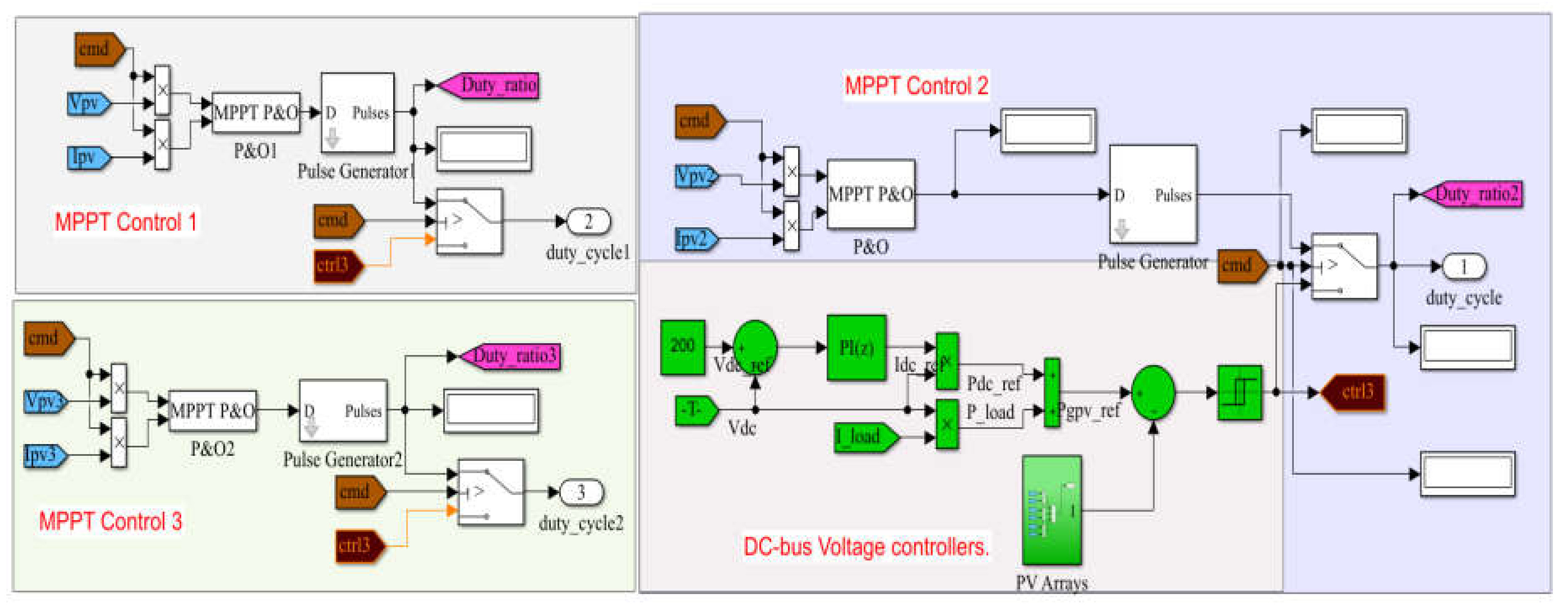
This article discusses a novel technique for enhancing electricity quality. The primary contribution of this work is the invention and implementation of a photovoltaic/battery energy storage (PV/BES) that provides uninterruptible power supply for local nonlinear loads operating in multimode mode. DSMCs implements MPPT control based on P&O in order to maximize the output of the solar array. Thus, instead of employing a conventional PI controller, DSMCs technology is used to manage and stabilize the DC-link voltage, boost overall system performance, and improve power quality by reducing harmonics in load current. Additionally, all photovoltaic boost converters that do not include storage components are regulated by the similar command used to adjust the DC-link voltage. This is a unique concept that is only used in this paper. Every possible system state has been taken into consideration.
The main advantages of this work are as follows.
  • New direct sliding mode controllers (DSMCS) with P&O algorithm are proposed in this study for DC-link voltage stability, which removes the effects of lower DC-link capacitor as well as enhances the photovoltaic system’s dynamic performance
  • The PV/BES is implemented with a BES backup, with a DC-DC bidirectional converter controlling the charging and discharging of the BES (BDC). The BDC with DSMCs eliminated the chance of the BES being overcharged or discharged and improve the dynamic performance of the entire system.
  • Presented a novel technique for controlling various parts of the system that assists in regulating the DC-link voltage in the presence of abrupt load variations and keeps the system operational even when batteries are not available. Additionally, it secures the batteries by only utilizing them when necessary, extending the life of the installation and The BDC with DSMCs was employed to eliminate the possibility of overcharging or discharging the BES. The load profile for the simulation is selected to replicate the many transitions between modes. Extreme weather and load variations put the system to the test. The results demonstrate the effectiveness of the proposed control.
  • The supply and load sides of a single system are used to combine the functions of solar power generation and power quality improvement. As a result, this system has a higher utilization rate than a traditional solar grid-connected system.
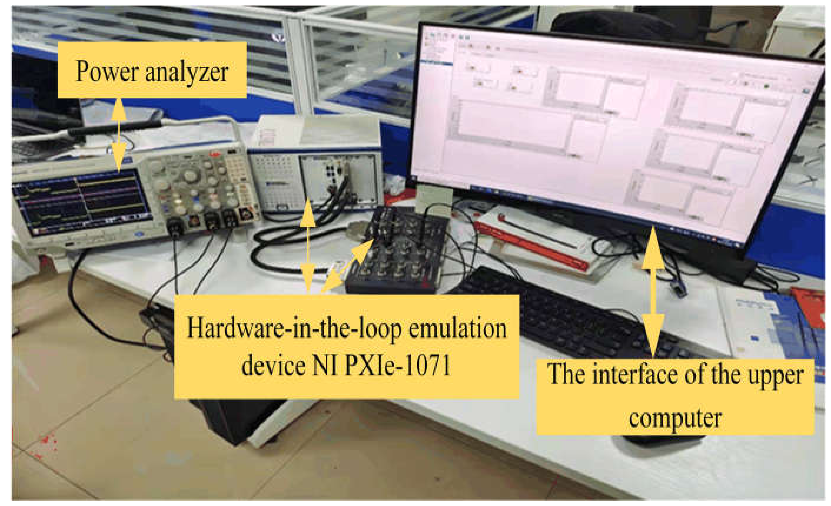
  • Evaluated the proposed DSMC utilized MATLAB/Simulink and Hardware-In-the-Loop experiment on the MT real-time control platform NI PXIE-1071.
This paper is organized as follows: 
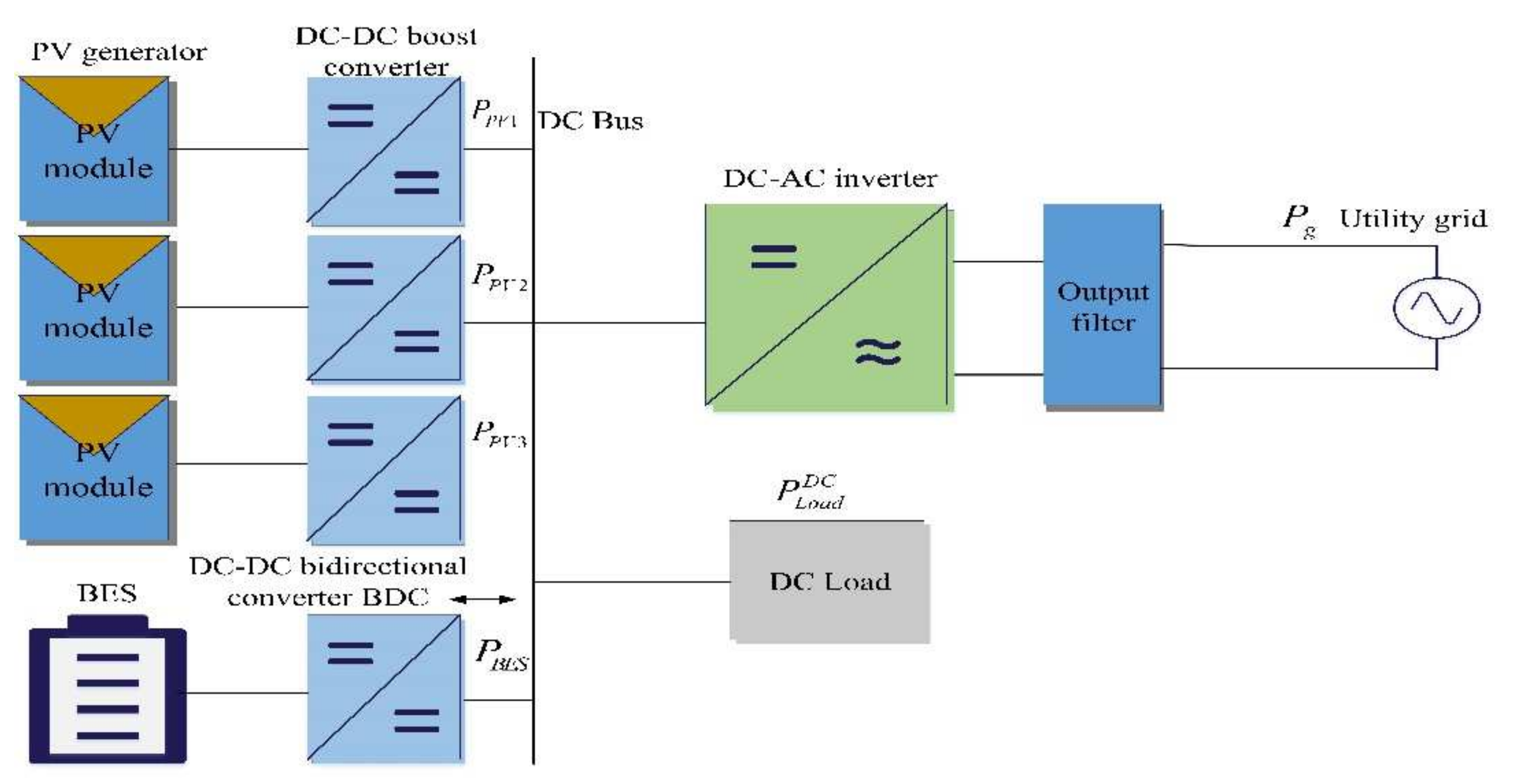
Section 2 represents the configuration and operation of the grid-connected hybrid PV/BES system. Section 3 and Section 4 address the DC-link capacitor reduced effects and proposed direct sliding mode control (DSMCs) technique, respectively. Section 5 addresses the performance discussion of DSMCs, comparing it with the PI controller. While Section 6 and Section 7 present the MATLAB/Simulink results and Hardware-In-the-Loop experiment on the MT real-time control platform NI PXIE-1071, respectively. Section 8 presents the conclusion.

2. Configuration and Operation of the Grid-Connected Hybrid PV/BES System

Three photovoltaic panels power the system, which is equipped with three direct DC-DC step-up converters, BES with a bidirectional buck-boost converter, DC-AC inverter, resident DC load, and AC load, as shown in Figure 1. The DC-DC step-up converters are the system’s most crucial component. Each photovoltaic array is made up of three photovoltaic panels connected in series to create a maximum output power of (810 W) at a maximum voltage of (105 V). The BESs have been set to operate at (48 V). Because connecting a series of batteries can generate an unbalance if one of the components is weaker than the rest, this design was chosen to extend the battery’s lifetime. Due to the fact that the batteries will run at the same voltage, they can be connected in parallel. Currents for charging and discharging will be apportioned according to capacity.
The DC-link voltage is set at ( V d c r e f = 200 V), taking the battery operating voltage into account and avoiding switching the bidirectional converter at duty cycles between 90% and 10%. As illustrated in Figure 1, BES is used to improve the regulation of the DC-link voltage. It is coupled by a bidirectional buck-boost converter, which regulates the charge/discharge processes under adverse operating situations such as fast variations in solar irradiation, load, and the incidence of faults.

3. DC-Link Capacitor Reduced Effects

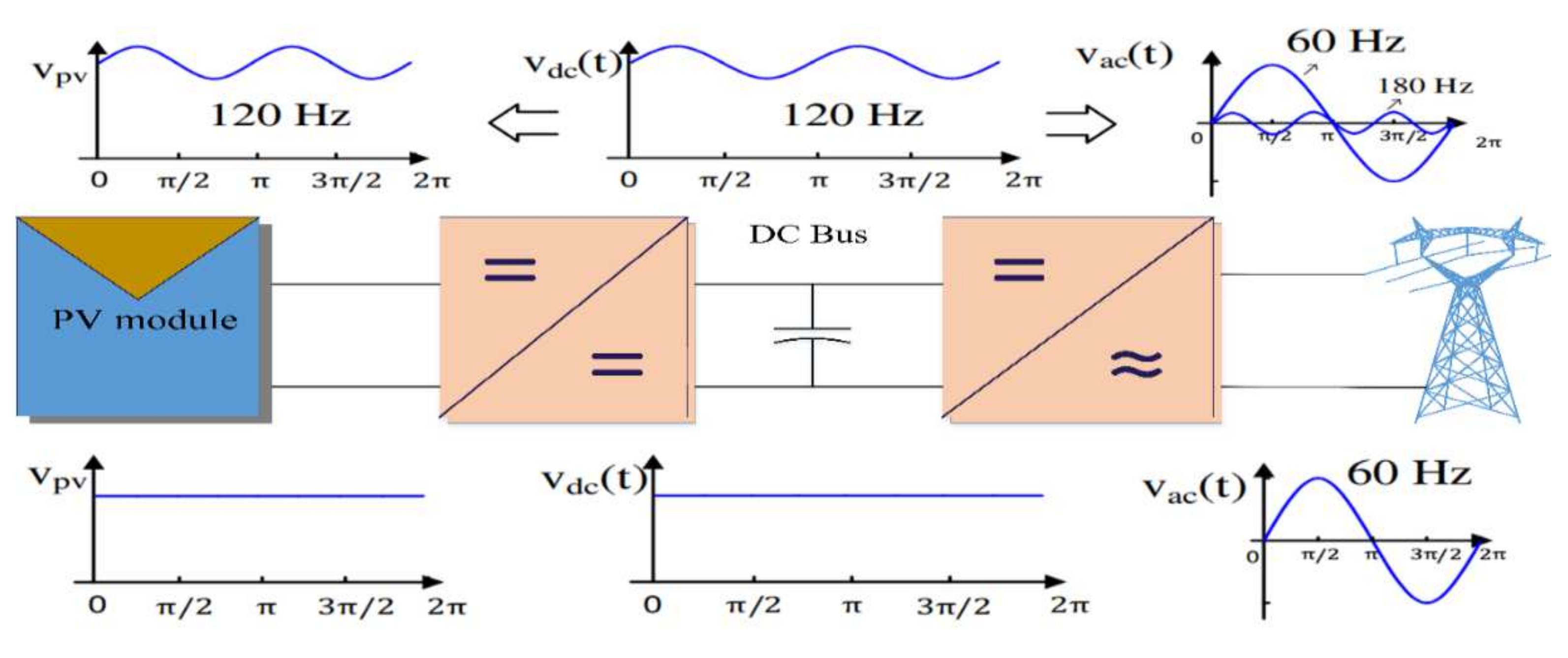
In grid-connected and stand-alone photovoltaic (PV) systems, the DC-link capacitor is the most significant passive component. To smooth DC-link voltage, traditional designs used a set of electrolytic bulk capacitors. A single low-inductance high-frequency film capacitor could be used to replace the electrolytic capacitors, according to a DC-link voltage and current ripple analysis. (1) Size reduction, (2) cost reduction, and (3) reliability enhancement are all significant outcomes. The complete photovoltaic (PV) and inverter can then be incorporated into a grid-connected system using the proposed high power film capacitor, reducing a significant quantity of wires and their associated costs and losses. However, in a high-power grid-connected system, this DC-link capacitor must deal with the following issues: (1) DC-link voltage fluctuation, (2) ripple current due to inverter switching, and (3) overall system dynamic performance concern. As seen in the Figure 2, when a large capacitor is utilized, the DC-link and PV terminal voltages are constant DC, as seen in the waveforms at the bottom of Figure 2. In addition, when a capacitor system is lowered, the DC-link voltage ripples at 120 Hz, resulting in a 120 Hz ripple in the PV terminal voltage and a 180 Hz component in the inverter output voltage, as illustrated in the waveforms at the top of Figure 2.
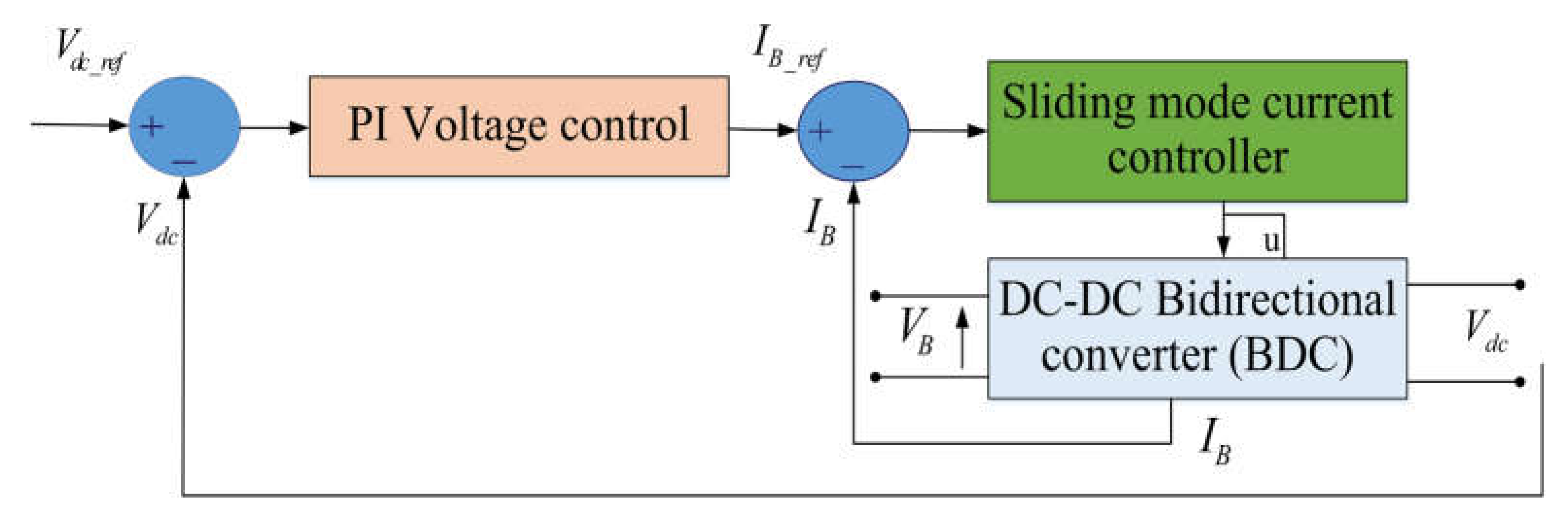
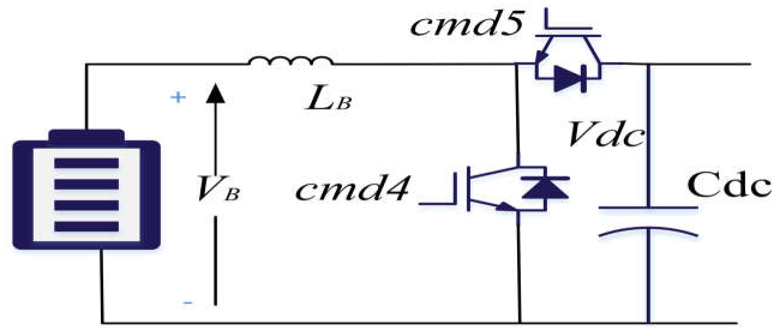
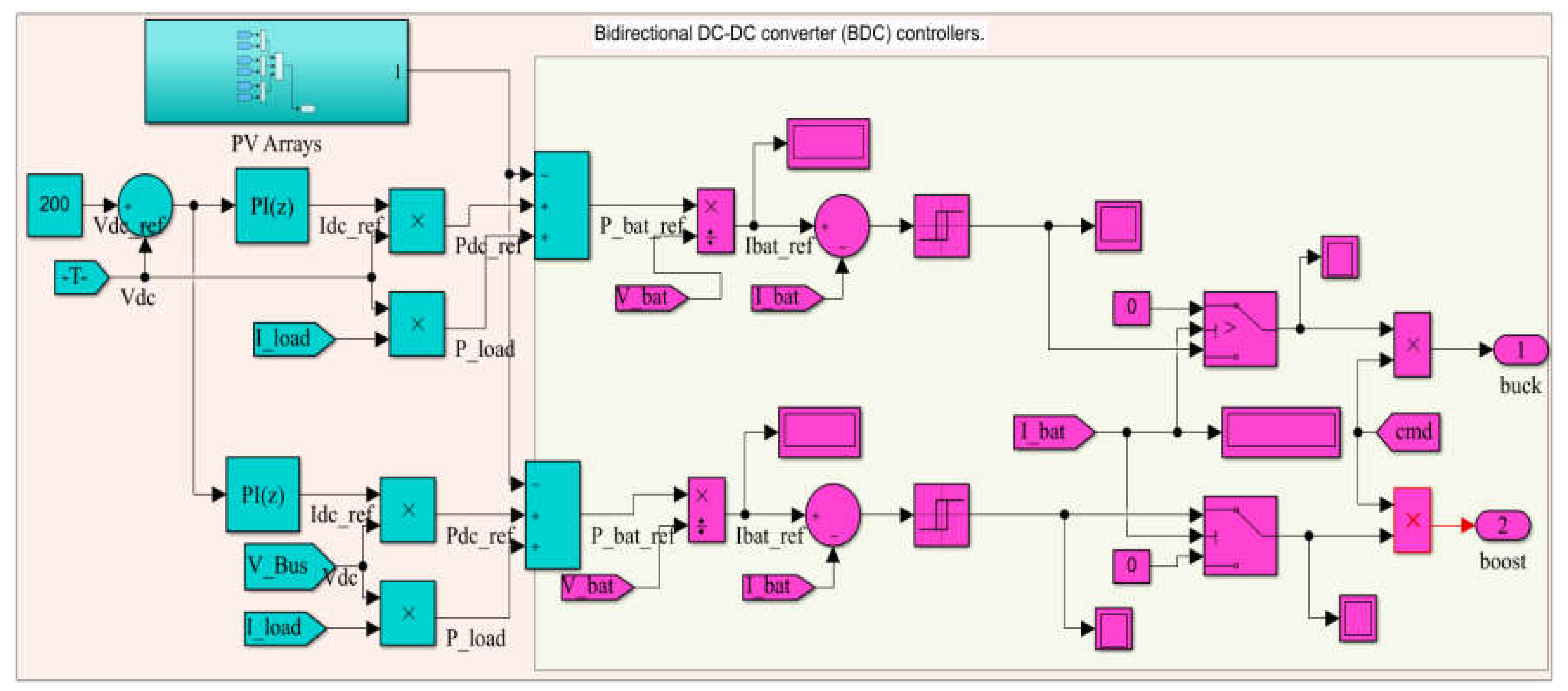
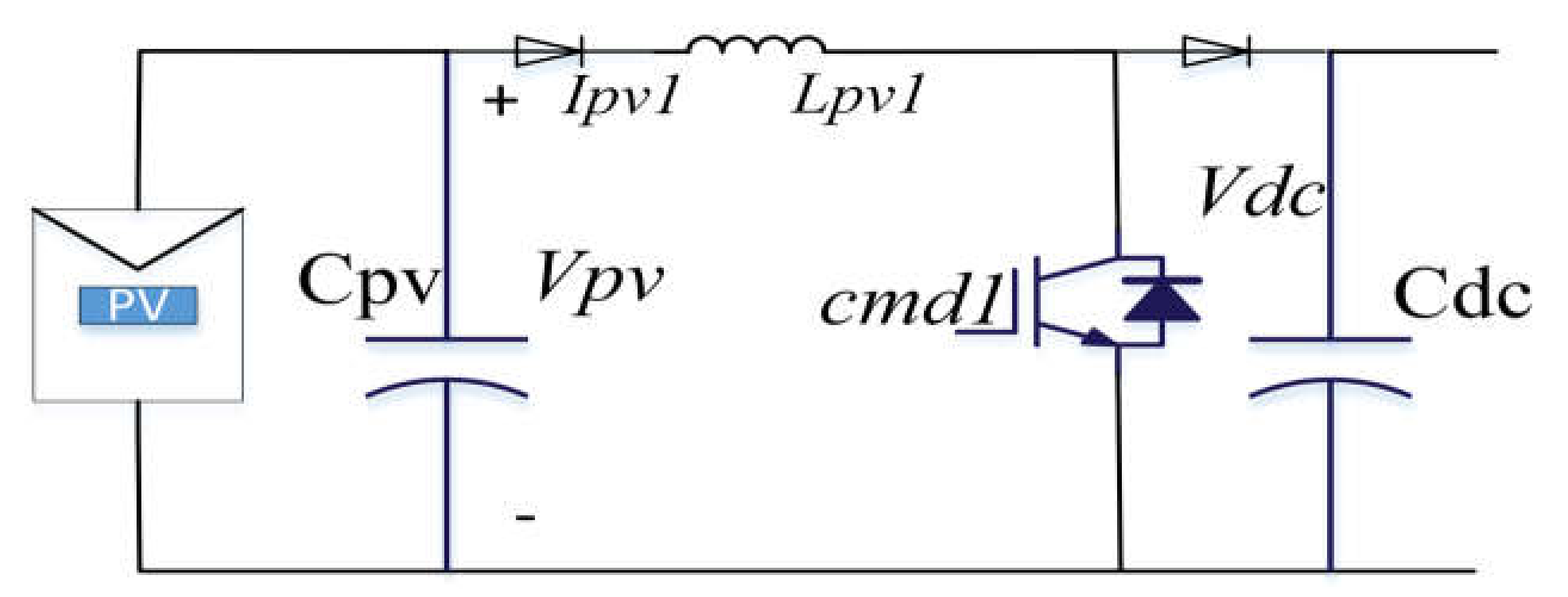
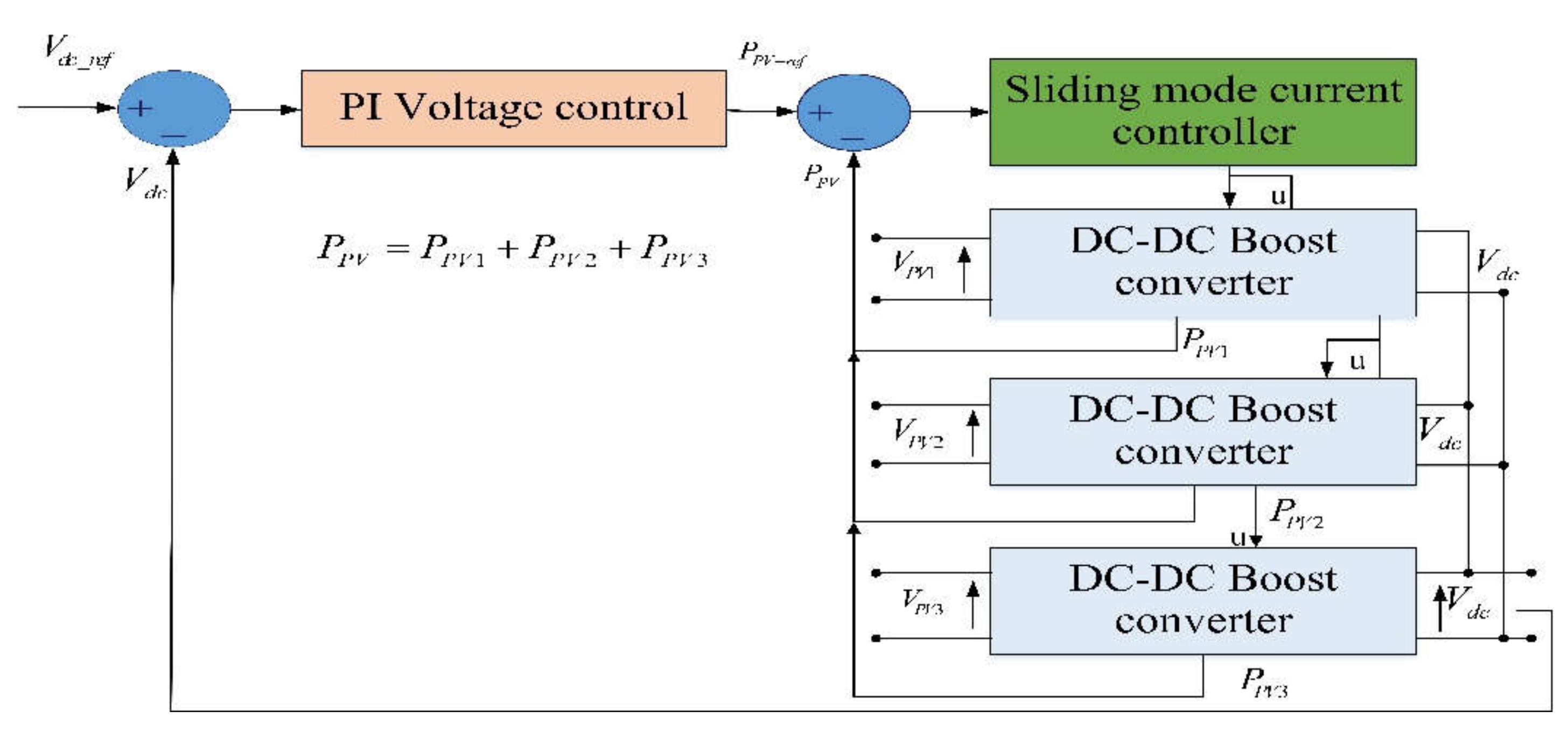
Due to the above-mentioned difficulties due to a reduced DC-link capacitor, the BES was required to adjust the DC-link overvoltage and undervoltage. Linking the batteries straightly to the DC-link stabilizes the system, but it has a significant impact on the battery life. Furthermore, because multiple batteries must be linked in series when the DC-link is set at a high voltage, this structure may generate an unbalance if one of the components is feebler than the rest. As a result, installing a bidirectional buck-boost converter between the batteries and the DC-link allows the system to be more versatile, but also makes voltage regulation difficult. Traditional PID controllers are not robust, and they operate poorly when substantial parameter fluctuations and load disturbances occur. In our system we proposed the direct sliding mode control (DSMCs) to control the bidirectional converter of the battery, to regulate the DC-link voltage to work at its reference voltage, and suppressed the output current ripples as well as control the AC-bus via DC-link voltage, because the ac-bus is greatly reliant on the DC-link voltage. DSMCs is a controller for the various components of the system that aids to adjust the DC-link voltage in contradiction of sudden load variations and maintains the system running even when batteries are not there. It also makes use of DC-DC step-up converters to increase the PV system’s dynamic performance. It protects the batteries by only utilizing them when they are needed, extending the installation’s lifetime.

4. Proposed Direct Sliding Mode Control (DSMCs) Technique

The numerous power converters control the system’s power flow. In the great majority of converters in use, the current dynamic is far faster than the output voltage dynamic [37]. As seen in Figure 3, to address the control challenge, a cascaded control configuration comprising of two control loops—control loop of both an inner current and an outer voltage—can be used [38]. Current control is often achieved using PWM or hysteresis control, whilst the voltage control is typically accomplished using standard linear control technology [39].
This section introduces a novel current control strategy based on the direct sliding mode control (DSMCs) technique. The next subsections discuss the design and synthesis of various controllers.

4.1. The DSMC for Bidirectional Converter (BDC)

Two controllers are required because the bidirectional converter (BDC) that links the batteries to the DC-link can function in either step-down or step-up mode [40,41]. In Figure 4, the commands for the buck and boost controllers are (cmd-4 and cmd-5), respectively. Only one command can be activated depending on the direction of the battery current. The switch controlled by this command is switched off since the other command has been set to 0.The bidirectional converter control’s goal in all situations is to set the DC-link voltage V D C to its reference voltage V D C _ r e f .

4.1.1. The Control Loop of Outer Voltage

The regulation of a DC-link voltage V D C to its desire voltage V D C _ r e f is accomplished by regulating the control current I D C flowing to the capacitor C D C to its reference current I D C _ r e f . The voltage control is obtained via the outer voltage loop’s PI controller, as seen in Figure 5. It is provided in the frequency domain via:
I D C _ r e f ( P ) = C P I ( P ) ( V D C _ r e f V D C ( P ) )
In the time domain, Equation (1) can be expressed as follows using the Inverse Laplace Transform:
I D C _ r e f = K P ( V D C _ r e f V D C ) + K i ( V D C _ r e f V D C ) d t
where K P and K i are parameters of the (PI) controller. Furthermore, by applying Kirchhoff’s current law, we obtain:
I D C = I P V 1 _ D C + I P V 2 _ D C + I P V 3 _ D C + I B _ D C I L o a d
where I P V 1 _ D C , I P V 2 _ D C , I P V 3 _ D C , and I B _ D C are the PV boost converters output currents and the current of the battery bidirectional converter, respectively.
Due to the discontinuous characteristics of the boost output current, it is hard to estimate its mean value in practice. Due to the existence of the inductor, the input current, on the other hand, has a continuous form and can thus be monitored and used in regulatory loops. By using the power conservation equation P I N = P O U T , the output current is calculated from the input current. The loss of power is not taken into account. Equation (3) is written as follows:
I D C V D C = I P V 1 _ D C V D C + I P V 2 _ D C V D C + I P V 3 _ D C V D C + I B _ D C V D C I L o a d V D C = I P V 1 V P V 1 + I P V 2 V P V 2 + I P V 3 V P V 3 + I B V B I L o a d V D C
then,
I D C = 1 V D C ( I P V 1 V P V 1 + I P V 2 V P V 2 + I P V 3 V P V 3 + I B V B I L o a d V D C )
All photovoltaic and load currents are considered disturbances in Equation (5). I D C is only regulated to its reference using the battery current I B . Equation (5) can be rewritten as follows: I D C _ r e f :
I B = 1 V B ( I D C V D C + I L o a d V D C I P V 1 V P V 1 I P V 2 V P V 2 I P V 3 V P V 3 )
Subsequently,
I B _ r e f = 1 V B ( I D C _ r e f V D C + I L o a d V D C I P V 1 V P V 1 I P V 2 V P V 2 I P V 3 V P V 3 )

4.1.2. The Control Loop Inner Current

A DSMCs is used to rapidly stabilize the battery current around the goal value achieved via the outer voltage loop. The DSMC’s resilience against system parameter changes further justifies this decision. According to the controller under investigation, the following proposition is made.
 Proposition 1. 
The following equation is the selection of the switching function:
s = I B _ r e f I B
For the operation of the buck mode:
u c m d _ 4 = 1 2 ( 1 s i g n ( s ) )
And for the operation of the boost mode:
u c m d _ 5 = 1 2 ( 1 + s i g n ( s ) )
In the sliding mode control offered by Equations (9) and (10), the current of the battery gets the target value in a finite time. As well as the DC-link voltage gets its reference value.
Proof. 
Both buck and boost modes must satisfy the sliding criterion s s ˙ < 0 for sliding mode SM to occur in the manifold s = I B _ r e f I B = 0 .
By providing a dynamic representation of the battery current in the buck mode:
d i B d t = 1 L B ( V B u c m d _ 4 V D C )
Taking into consideration Equation (9), u c m d _ 4 = 0 when s > 0, and Equation (8) is used:
s s ˙ = 1 L B ( I B _ r e f I B ) > 0 ( V B ) > 0 s s ˙ < 0
when s < 0, u c m d _ 4 = 1 and
s s ˙ = 1 L B ( I B _ r e f I B ) < 0 ( V B V D C ) < 0 s s ˙ < 0
As a result, s = 0 (sliding surface) is appealing during a finite time.
By providing a dynamic representation of the battery current in boost mode:
d i B d t = 1 L B ( ( u c m d _ 5 1 ) V D C + V B )
Taking into consideration Equation (10), u c m d _ 5 = 0 when s < 0, and Equation (8) is used:
s s ˙ = 1 L B ( I B _ r e f I B ) < 0 ( V D C + V B ) < 0 V ˙ < 0
when s > 0, u c m d _ 5 = 1 and
s s ˙ = 1 L B ( I B _ r e f I B ) > 0 ( V B ) > 0 V ˙ < 0
As a result, s = 0 (sliding surface) is attractive for a finite time.
Based on the foregoing calculations, the battery current will get its target value I B _ r e f in a finite period that is dependent on the beginning condition in both modes. Only one command may be sent while in active mode. The other command has a value of 0. □

4.2. The DSMC for PV Boost Converters

Three controllers are required to make all the PV boost converters work with maximum power point tracking (MPPT). Each boost has its own controller, which is substituted by another controller when it comes time to manage the DC-link voltage. Figure 6 illustrates the boost converters utilized in each photovoltaic array.

4.2.1. Maximum Power Point Tracking Method

The maximum power point tracking (MPPT) method can be utilized with a variety of MPPT algorithms. In this investigation, the P&O technique was used to track the maximum power point. The algorithm’s simplicity and effectiveness support this judgment. A flowchart summarizing the perturb and observe method phases can be seen in [42,43].

4.2.2. The Controller of Dc-Link Voltage

All photovoltaic step-up converters turn to stabilize the DC-link voltage when the battery bank is unplugged, and a single sliding mode controller is used. As seen in Figure 7 and Figure 8, this controller resembles a bidirectional converter in appearance. The photovoltaic boost converters’ overall power output is regulated by two cascaded control loops: an exterior voltage control loop and an internal power control loop.
(1)
Control loop of the outer voltage.
By utilizing the power conservation connection, we get
P D C = P P V 1 + P P V 2 + P P V 3 P L o a d = P P V P L o a d
PV powers P P V 1 , P P V 2 , and P P V 3 are employed as controller components for the dc-bus power P D C in this controller (Figure 8).
P P V = P D C + P L o a d
Set P D C to its reference P D C _ r e f     . Equation (18) turns into.
P P V _ r e f = P D C _ r e f + P L o a d
or
P P V _ r e f = I D C _ r e f V D C + P L o a d
where I D C _ r e f is determined by the outer voltage loop of proportional-integral (PI) controller. It is provided by in the frequency domain in the following equation:
I D C _ r e f ( P ) = C P I ( P ) ( V D C _ r e f ( P ) V D C ( P ) )
In the time domain, Equation (21) can be expressed as follows using the inverse Laplace transform:
I D C _ r e f = K P ( V D C _ r e f V D C ) + K i ( V D C _ r e f V D C ) d t
where ( K P ) and ( K i ) are the parameters of the PI controller.
(2)
Control loop of the inner power.
A DSMCs is also used to offer quick PV power stabilization around the target value acquired via the outer voltage loop as seen in Figure 8. The following proposition is made by the controller under examination.
 Proposition 2. 
The switching function is provided as follow:
s = P P V _ r e f P P V
At the moment, simply Equation (9) controls all photovoltaic converters. The total photovoltaic power generated will get the requisite level in a limited length of time, and also the DC-link voltage will likewise reach the required level.
All boost controllers for photovoltaic systems must provide the following features:
u = c m d _ 1 = c m d _ 2 = c m d _ 3 = 1 2 ( 1 s i g n ( s ) )
 Proof. 
The demonstration of the aforementioned sliding surface s = P P V _ r e f P P V = 0 attractiveness is identical in boost mode of the bidirectional converter (BDC). □
Under changing climatic conditions, each PV array’s power characteristics may take on different shapes, and their sum may cause the shape distortion of photovoltaic characteristics. The voltage used by all PV arrays is the same V P V =   V P V 1 = V P V 2 = V P V 3 when the PV DC-DC step-up converters are controlled by a single command, as seen in Figure 7 and Figure 8, but they generate various powers P P V 1 , P P V 2 , and P P V 3 . In this approach, the PV arrays are viewed as a single PV producer, operating at a voltage of P P V and producing a power of P P V =   P P V 1 + P P V 2 + P P V 3 . The latter must be equal to the P P V _ r e f intended power. The novel technique of using a single command for all photovoltaic step-up converters increases the system’s efficiency. Under conditions of significant load variation, the duty cycle will fluctuate continuously to meet the load power demand, a situation in which boost converters perform exceptionally well. This technique addresses an issue that may develop in the system discussed in [44] when PV DC-DC step-up converters are operated distinctively and inversely in the similar mode.

4.3. Inverter Control

To supply AC loads, we employed a simple common 3-ph inverter with LC filter in our system. In terms of stability, the AC-bus is greatly reliant on the DC-link voltage. The waveforms of AC voltage and current show how excellent or terrible the AC-bus is.

5. Performance Discussion

The dynamic resistance of a single-stage grid-connected system voltage source control (VSC) with a low DC-link capacitance was investigated in [17]. The conventional single-stage model, on the other hand, is insufficient because it only contains three states. Furthermore, the step-up transformer, direct current cables, grid stiffness, phase-locked loop (PLL), and AC voltage regulation dynamics are not included in the dynamic model. Furthermore, no solution or mitigation strategy has been offered to improve the single-stage system’s stability and permit the integration of solar generators with lower DC-link capacitance.
DSMCs is used in this work because its changeable structure corresponds to the characteristics of the converter. The switching frequency variation and chattering phenomena, on the other hand, are two significant properties of DSMCs. The DSMCs and P&O can be used to successfully solve the chattering problem. There are two techniques for concurrently overcoming the flaws of variable switching frequency and taking use of DSMCs. To fix switching frequency, one option is to install an additional hardware circuit. Obviously, this method will increase system costs and is incompatible with distributed generators and loads’ scalability and plug-and-play capabilities in DC microgrid. Alternatively, DSMCs can be combined with other methods of control.
In this work, the proposed converter allows the use of small DC-link capacitors in stand-alone PV/BES systems; therefore, using a thin film capacitor instead of an electrolytic capacitor can improve the reliability of the system. The converter also realizes low-frequency ripple free maximum power point tracking (MPPT) based on sliding mode control. Firstly, a DC-link voltage synchronization control is devised to mitigate the effect of capacitance decrease. Then, a thorough design of a power mitigation control is proposed that is based on the DSMC-BDC dynamic model to prevent the DC-link from propagating substantial low-frequency voltage changes to the photovoltaic side. In addition, a new P&O-DSMC- algorithm is suggested, which not only ensures the high efficiency of MPPT, but also ensures the fast maximum power extraction under rapid irradiation and load changes.
A bidirectional buck-boost converter is connected to the DC-link, and an DSMCs control technique is created such that the buck-boost converter may bypass the harmonic current instantly, preventing harmonic current from flowing into the DC-link capacitor and load. The voltage ripples can be significantly decreased since the harmonic current is bypassed instantly. To filter out the high-frequency switching harmonics created by the extra current compensator, only a film capacitor is required in general. The voltage ripples problem is then transformed into instantaneous current tracking. Because of the well-known repetitive control approach DSMC’s great performance in tracking periodic signals, a repetitive controller for instantaneous harmonic current compensation with a set switching frequency has been devised. Although the proposed technology is intended for rectifiers, it can easily be applied to inverters and fuel cell and battery-powered devices.
Finally, it can be concluded that employing thin film capacitors at the DC-link with a standard PI controller is unfeasible. DSMCs filter is used in the bus control system to prevent double frequency ripples from propagating to the output current control system, lowering the THD of the output current. DSMCs is suggested in this study to reduce dc-link voltage overshoot and undershoot. As a result, as compared to the traditional way of employing a PI controller, this method helps reduce overshoot, undershoot, and THD values.

6. Simulation Results and Discussions

The integration of the PV and battery connected system is simulated in MATLAB/Simulink using Simscape power systems toolbox, which estimate the performance of the control strategy upon the proposed grid-tied PV solar system connected to battery storage system.

6.1. Four Operation Modes Can Be Distinguished Based on the Generated Power and Load Demand

6.1.1. Battery Discharging with a Lack of Energy

Batteries are used to bridge the gap or supply the entire load during off-peak hours, when solar energy output is much less than the local load requirement. By regulating the power flowing from the BES, the battery’s BDC adjusts the DC-link voltage. The battery bank’s voltage (48 V) is increased to match that of the DC-link (200 V). All solar photovoltaic step-up converters employ maximum power point tracking method. An inverter is designed to power only AC current loads.

6.1.2. Battery Charging with the Surplus of Energy

Excess photovoltaic electricity is used to charge the battery when it exceeds local load requirements. In this way, the battery BDC controls the DC-link voltage. The DC-link voltage lowers to the BES voltage. In photovoltaic arrays, all DC step-up converters track MPP. The inverter powers AC loads.

6.1.3. The Absence of Batteries with Lack of Energy

All loads are disconnected once the batteries have been discharged. After the PV generator has charged the batteries to a specific level, the loads can be reconnected. The battery bidirectional converter controls the power flow from or to batteries in both cases, regulating the DC-link voltage. MPPT is compatible with all PV arrays converters. This mode can be considering with mode two.

6.1.4. The Absence of Batteries with Surplus of Energy

When the BES is entirely charged, the bidirectional DC-DC converter on the battery is unable to protect it from overcharging. No MPPT step-up converters can operate in this mode because the solar generator’s maximum power output exceeds the local load demand. In reality, DC-link regulation is the responsibility of a single regulator. The goal of shifting to DC-link regulation for all boost converters is to minimize duty cycle variations while maintaining high boost converter efficiency.

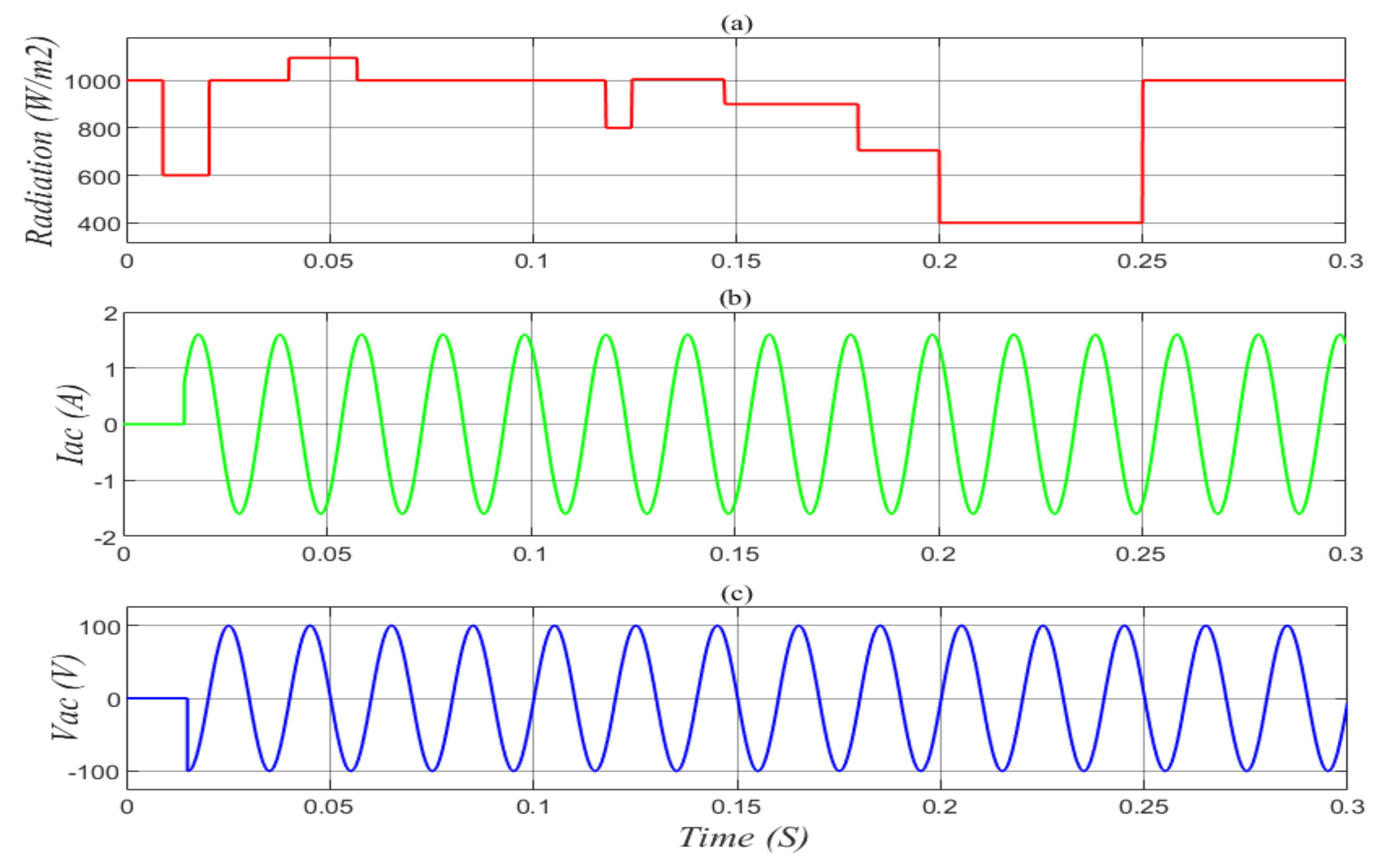
6.2. The Load Variation Scenario with Radiations Changes

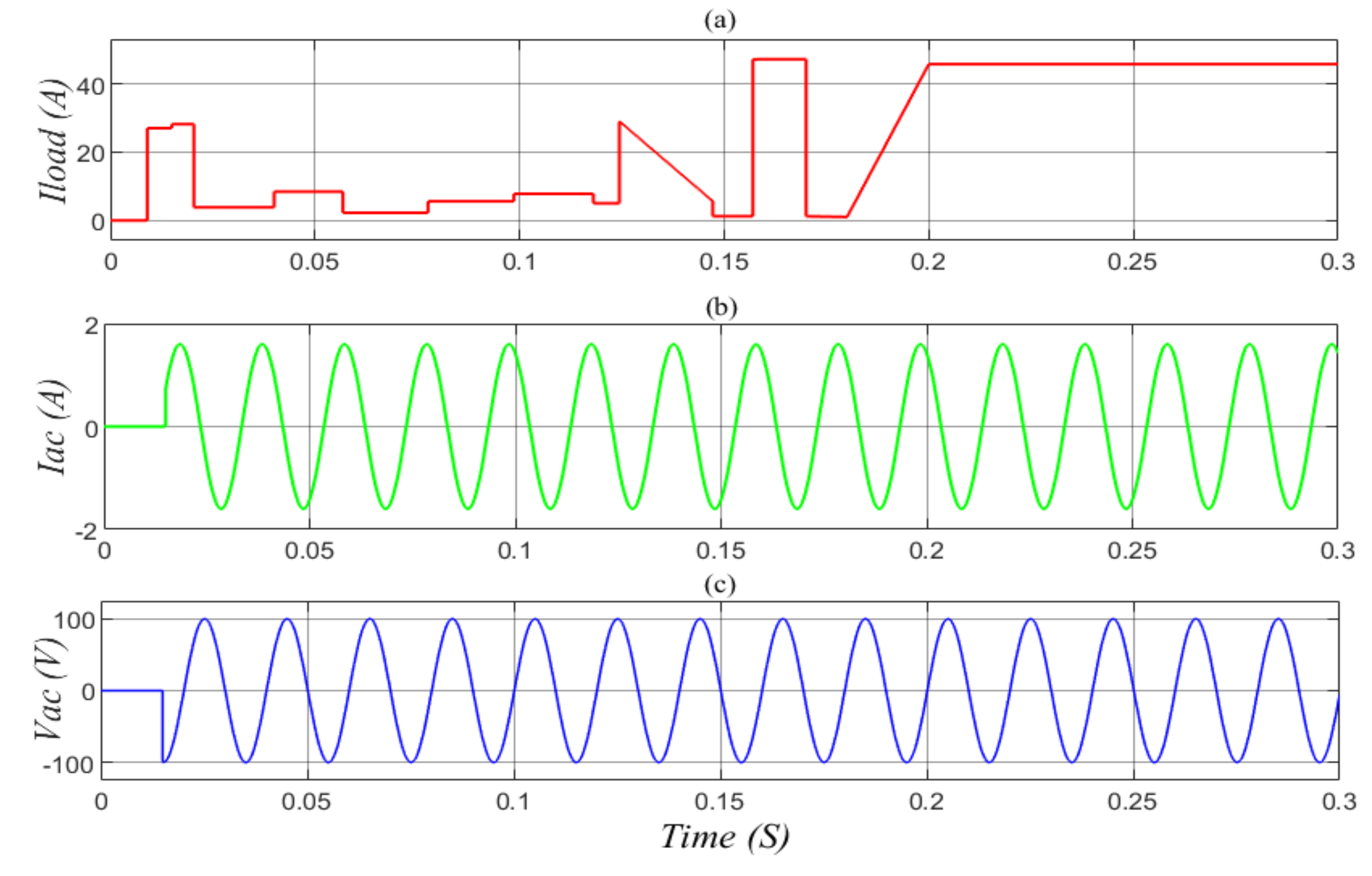
In this section the control strategy was tested under load variations, as seen in Figure 9a, and all the PV systems had different solar radiation conditions: first module—1000 W/m2, second module—800 W/m2, third module—600 W/m2, as seen in Figure 1.
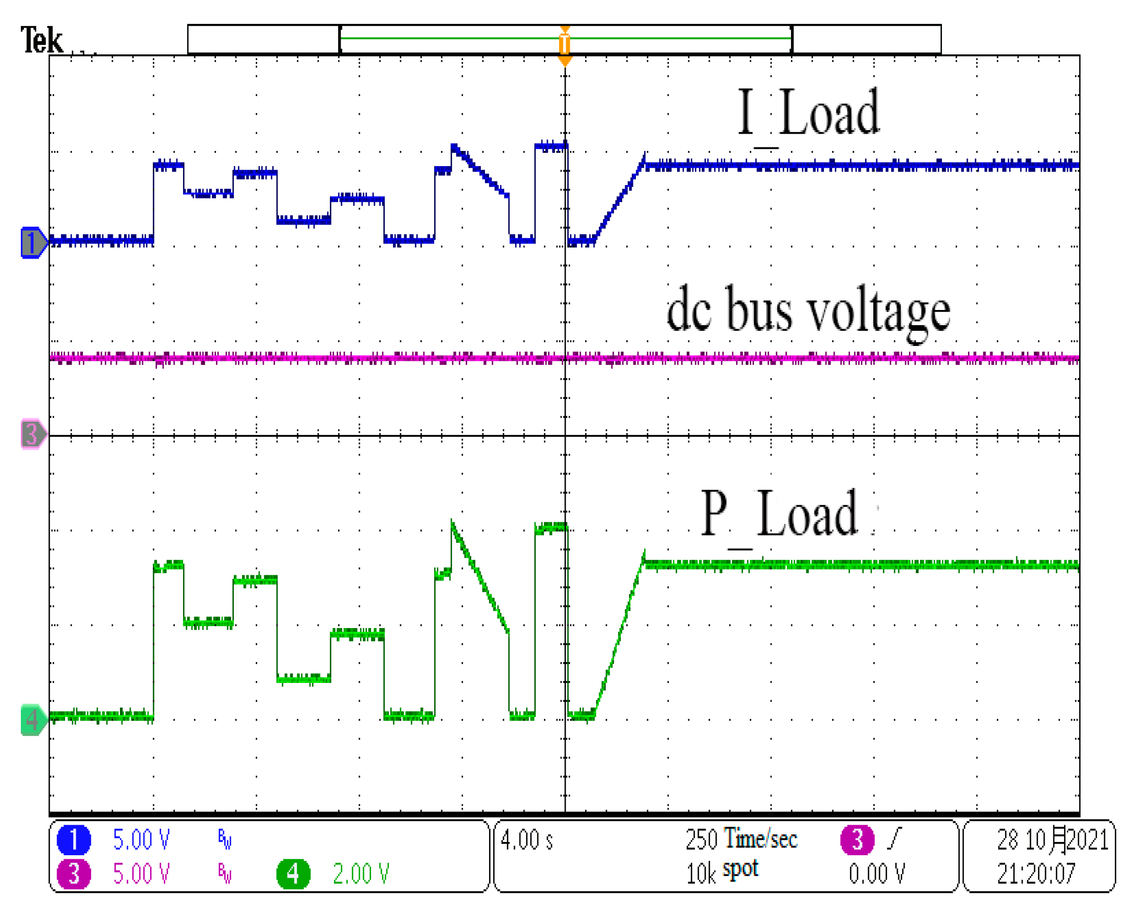
The power, current, and voltage variations of various components of the system throughout the simulation period are depicted in the following curves. The curves were divided into ten patches, which were used to make the results easier to read and understand the alternates between mode. Mode one has five patches, which are [(0 s–0.009094 s), (0.020448 s–0.0312 s), (0.12 s–0.124454 s), (0.142 s–0.157082 s), and (0.17082 s–0.1843 s)]; modes two and three have four patches, which are [(0.009094 s–0.020448 s), (0.124454 s–0.142 s), (0.157082 s–0.17082 s), and (0.1843 s–0.3 s)]; and mode four has one patch, which is (0.0312–0.12). It is worth noting that mode three can occur through mode two, as it depicts a serious circumstance in mode two. Additionally, the ten patches are given below: ( t 0 = 0   s , t 1 = 0.009094   s , t 2 = 0.020448   s , t 3 = 0.0312   s , t 4 = 0.12   s , t 5 = 0.124454   s , t 6 = 0.142   s , t 7 = 0.157082   s , t 8 = 0.17082   s , t 9 = 0.1843   s , t 10 = 0.3   s ).

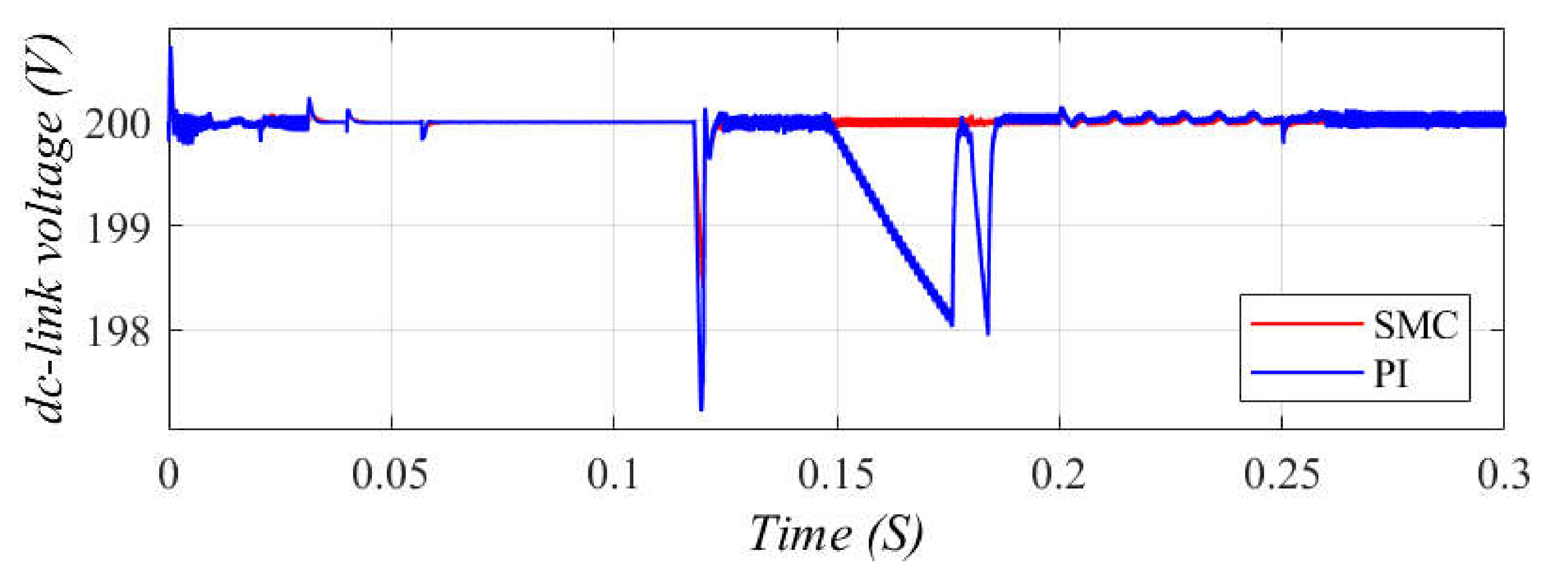
6.2.1. PI Controller

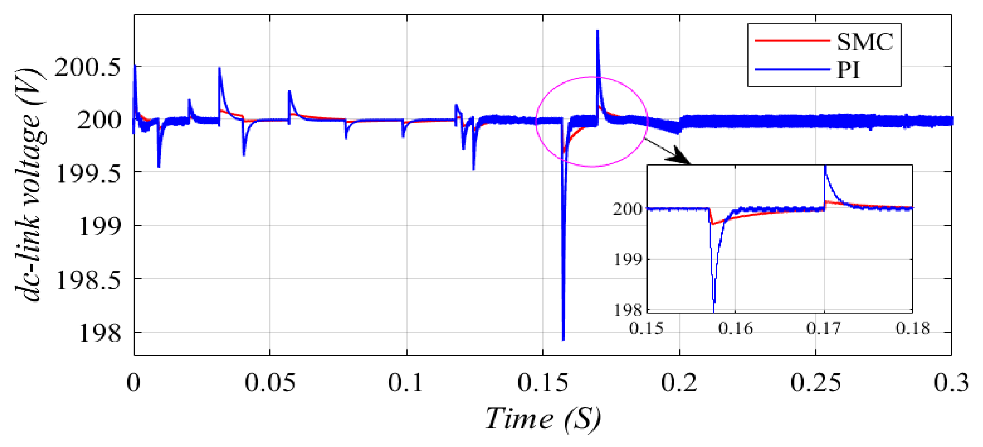
With this method, the PI controller is modeled with a small capacitor (10 µF) for the DC-link and a high sample rate of the DC-link controller. Figure 10 shows the reactions when the DC-link capacitor is 10 µF. In this circumstance, the gains of the PI controller are selected to be p = 0.06 and I = 1.3. In addition, the DC-link voltage overshoots and the overshoots are 0.75 and 2.2 V, respectively.

6.2.2. DSMC Techniques

The DSMCs controller is modeled with a small capacitor (10 µF) for the DC-link and a high sampling rate for the DC-link controller. Figure 10 shows the reactions for the case that the DC-link capacitor is 10 µF. In this circumstance, the DSMCs controller reacts well by regulating the intermediate circuit voltage better than the PI controller. In addition, the overshoots of the DC-link voltage are 0.2 and 0.3 V, respectively.
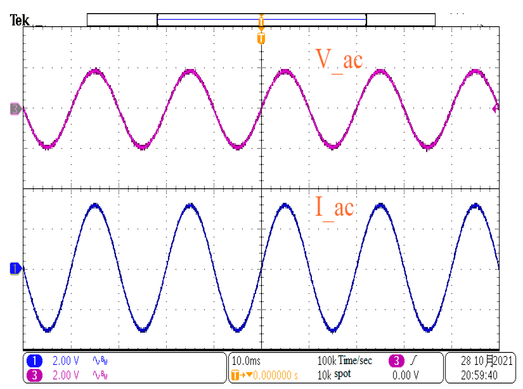
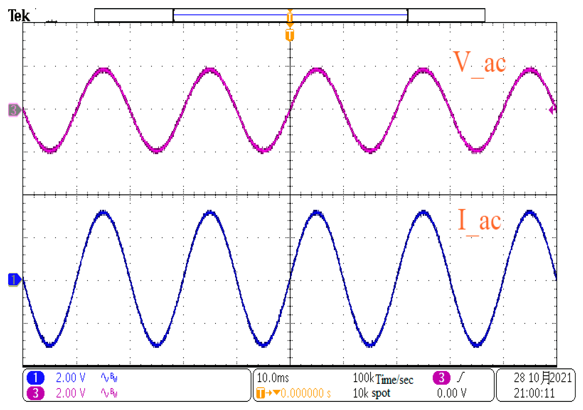
The load pattern used to examine the control strategy’s robustness is shown in Figure 9a. The pattern is designed to demonstrate all probable switches between modes. The AC load begins at time (0.015 s), as seen in Figure 9b,c, and the load current curve is seen in Figure 9a. When we look at the AC amounts, such as current and voltage, we can see that the AC-bus is completely reliant on the DC-link, which performs admirably. The photovoltaic system considers all AC and DC loads to be a single load or disturbance.
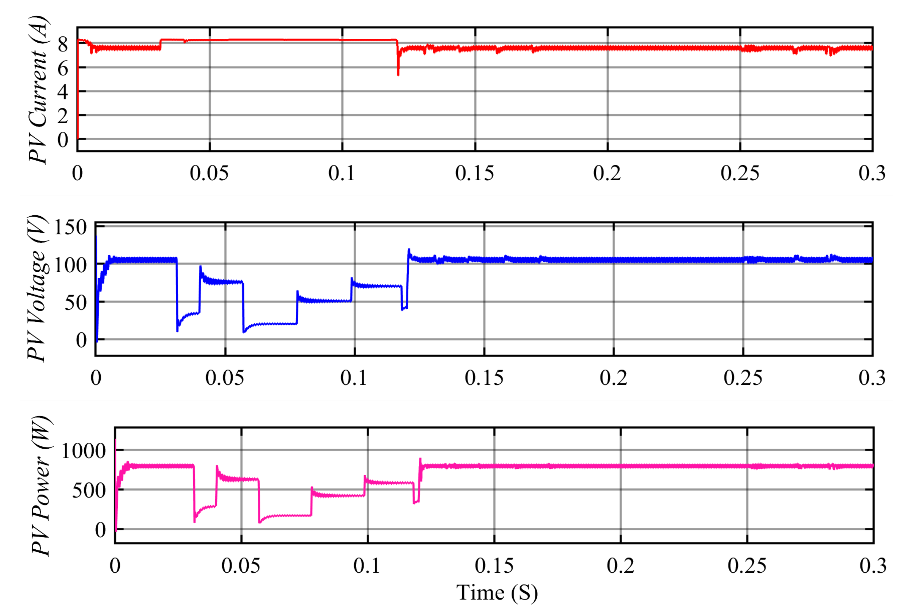
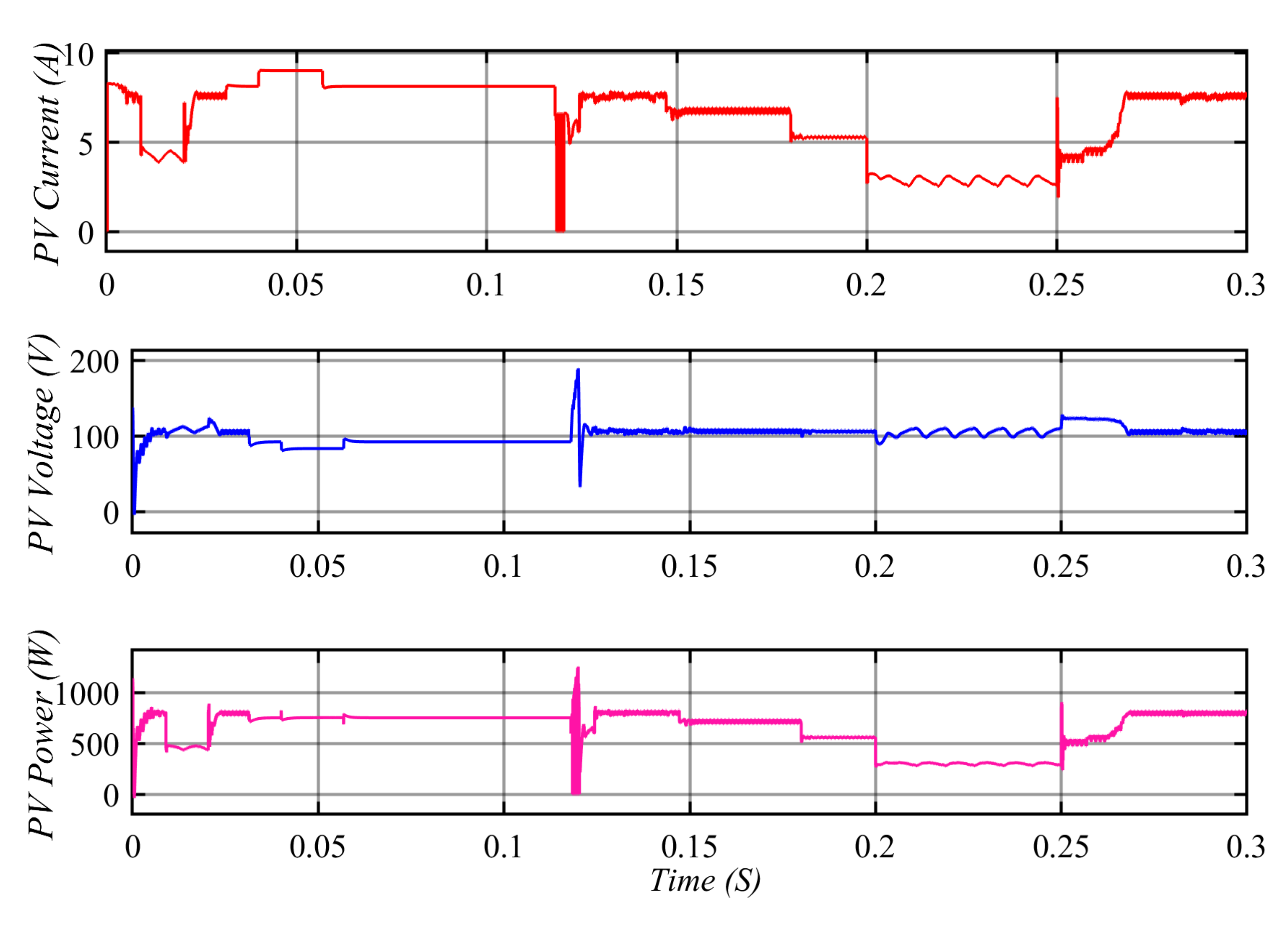
Due to the lack of load at the begin, the PV arrays charge the batteries until approximately time equal to (0.01 s mode two). Each MPPT-enabled photovoltaic array controller begins by identifying the MPP of the PV arrays. When they get the MPP, they preserve the maximum rate of power generation. As illustrated in 
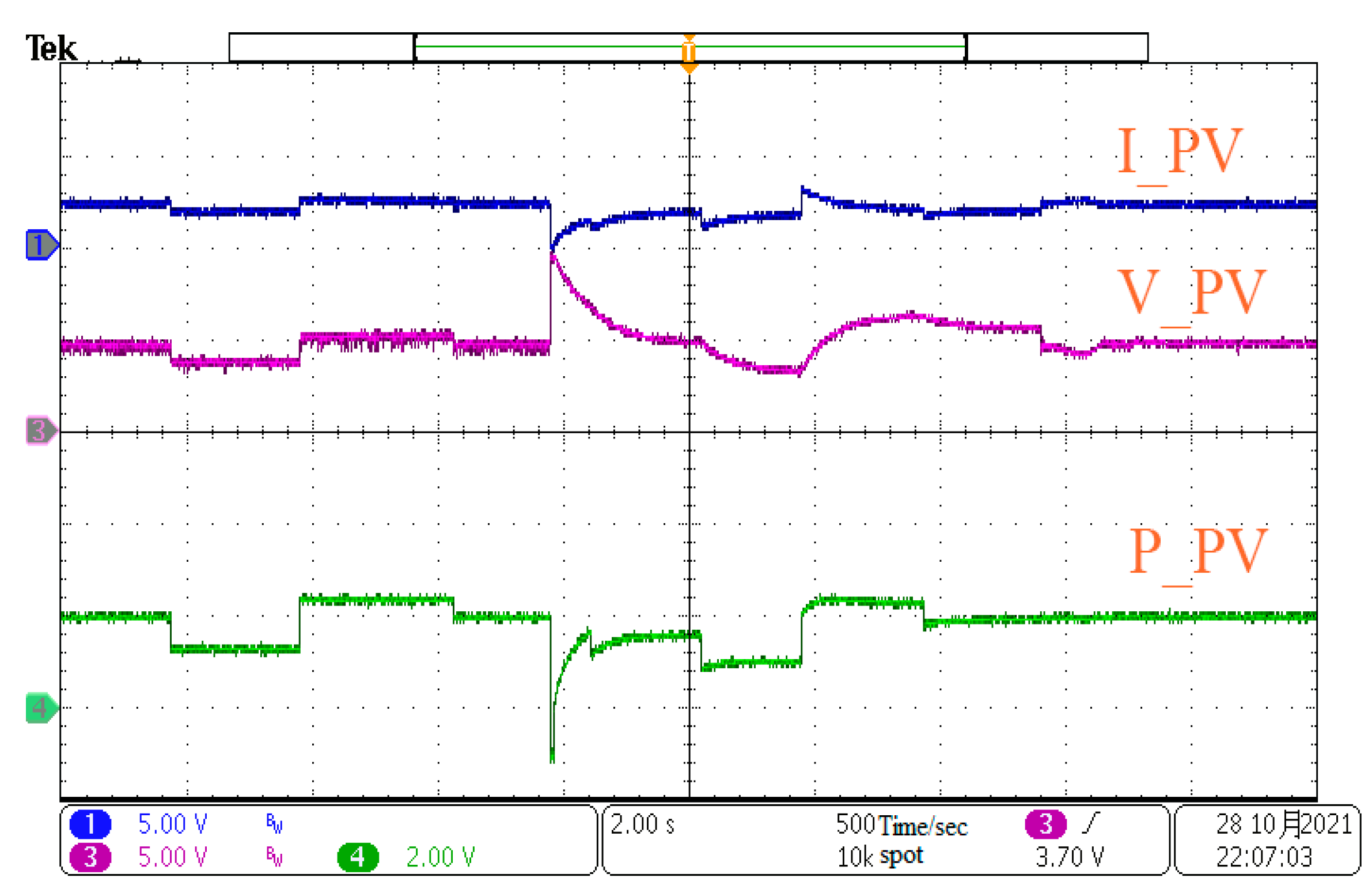
Figure 1, photovoltaic arrays are visible to a range of radiations, which has a direct effect on their maximum power output. The maximum power, voltage, and current are generated by the first photovoltaic array depicted in Figure 11, the second photovoltaic array and the third photovoltaic array have similar curves but distinct values.
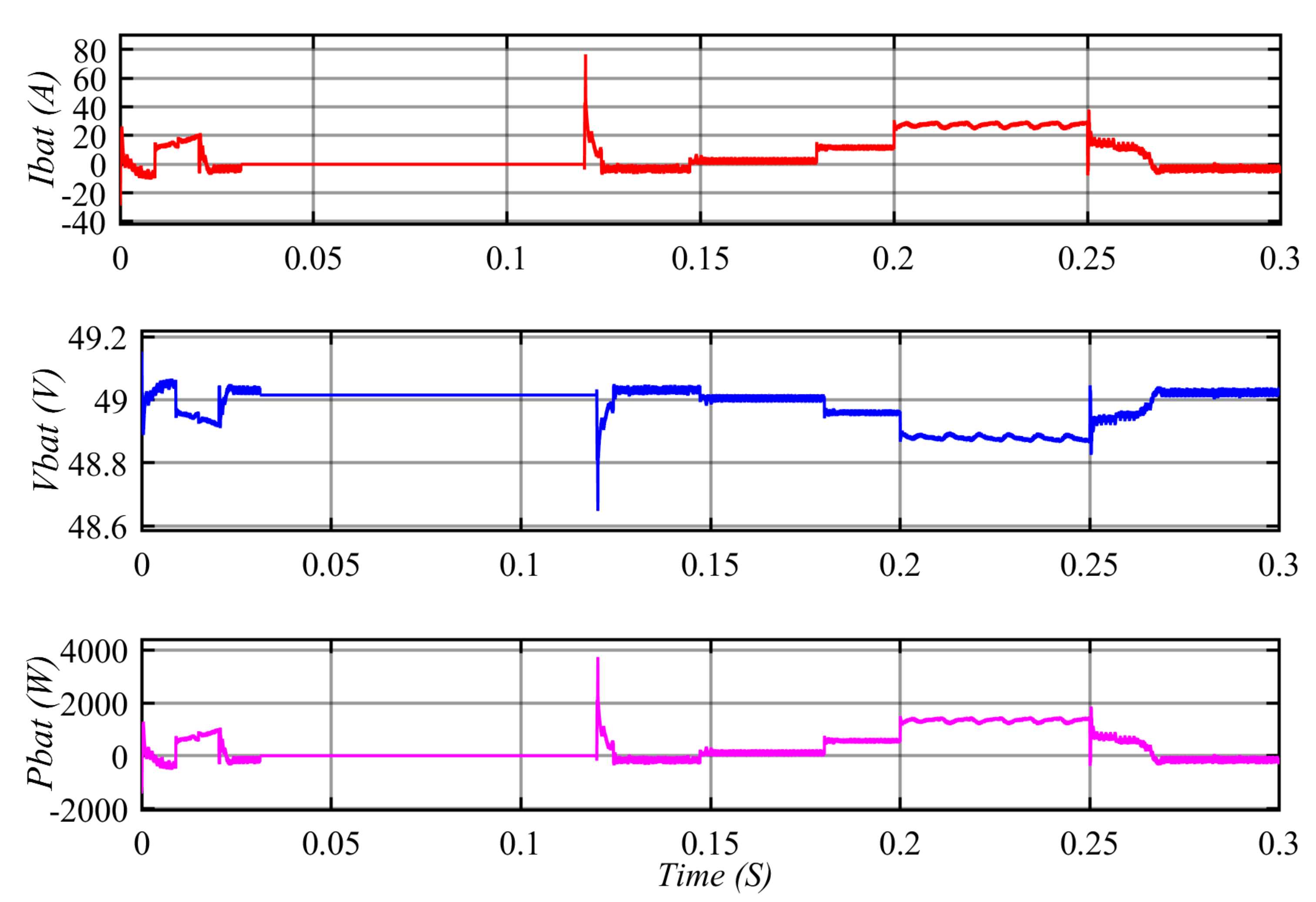
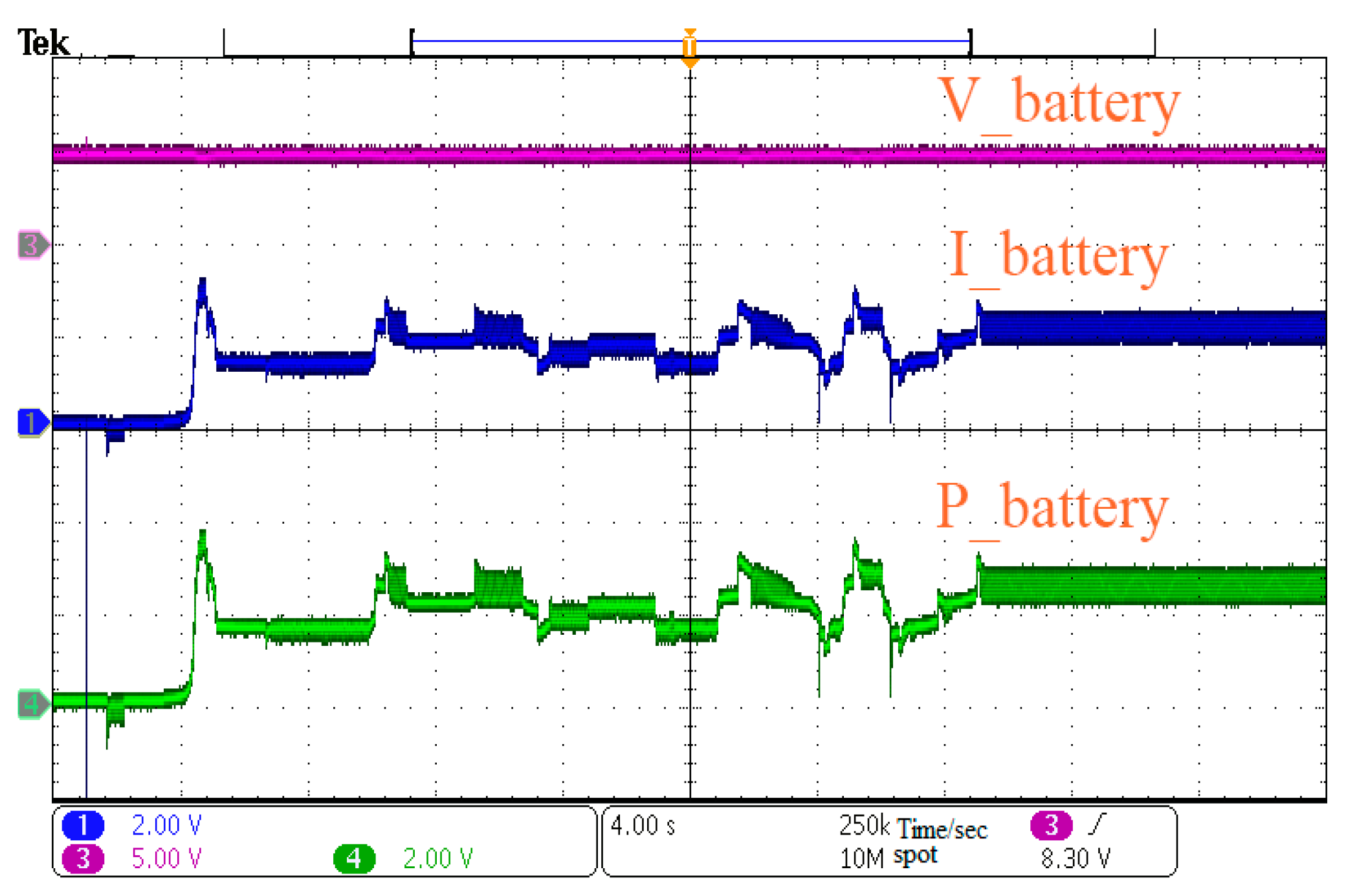
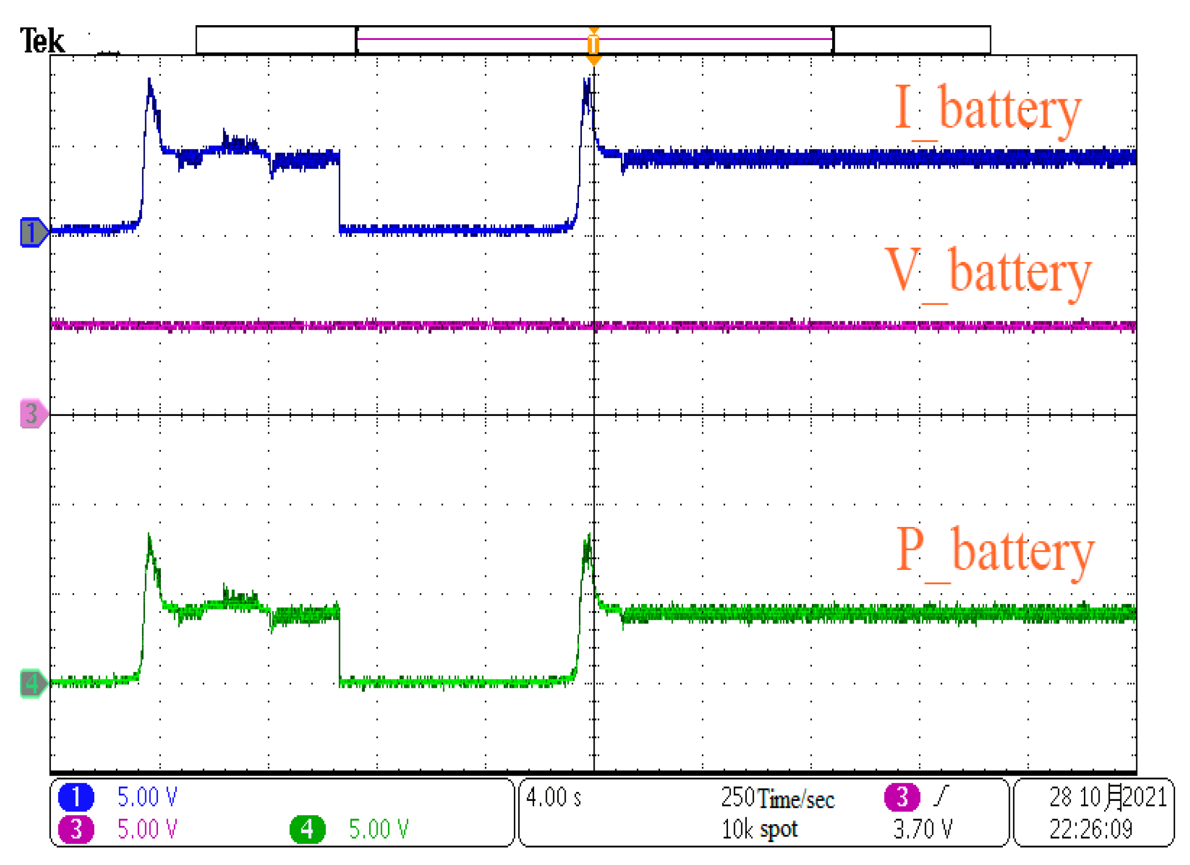
Because the whole amount of energy generated is used to charge the batteries, as demonstrated in Figure 12, the BES controller runs in step-down mode, guaranteeing that the DC-link voltage remains constant, as illustrated in Figure 10, which reflects the desired voltage to be regulated. All observable peaks in the DC-link voltage curve are the result of abrupt switching of one or more power supplies or DC/AC loads.
At approximately t = 0.01 s, the system moves to mode one, resulting in an unexpectedly large current demand, as illustrated in Figure 9a. Due to the fact that the solar energy generated is insufficient to meet the local load requirement, the batteries are used to compensate, and the BES converter switches from step-down to step-up mode, as depicted in Figure 12. As is readily apparent, the battery boost controller’s dynamic response to variations in load power is extremely fast at the moment, with only a (0.5 V) (0.25%) shift in the DC-link voltage. The photovoltaic system converters continue to operate using MPPT. We observe that the abrupt increase in local load has no influence on the controllers of any photovoltaic arrays.
When the time gets to 0.02 s, the load demand rapidly falls below the amount of PV energy produced, and the system switches to mode two. Excess energy is used to refuel the batteries. When the load changes abruptly, as seen in Figure 12, the BES back regulator exhibits a great and unusually fast dynamic behavior in the DC-link voltage. We see a variation of only (0.2 V) (0.1%). The controllers for the photovoltaic arrays remain in MPPT mode and are unaffected by the load shift.
Throughout the simulation (after time = 0.12 s), the system alternates between modes one and two in response to the power imbalance between load demand and generated power. To determine the capacity of the control system, abrupt and severe load fluctuations are applied. The most notable fluctuation happens when the current load reaches a high of around 50 A. The magnitude of the variation is 2 V and is less than 1% of the DC-link voltage value, confirming the controllers’ excellent enactment. The photovoltaic array controllers are unaffected by load variations and exhibit excellent resilience in their presence.
We tried the BES overcharge threshold in order to get the system to run in mode four due to the time necessary to charge the batteries in simulation. As illustrated in Figure 12, the battery converter is unplugged between t = 0.03 s and t = 0.12 s. During this time period, a single DSMCs will regulate the PV array converters. As a result of the switch from maximum power point tracking to DC-link voltage regulation, no maximum power will be given. We can determine how resilient the PV array controller is to load changes by examining the DC-link voltage curve over this time period. The highest fluctuation occurs at the time of mode switching and all subsequent fluctuations have a negligible effect.

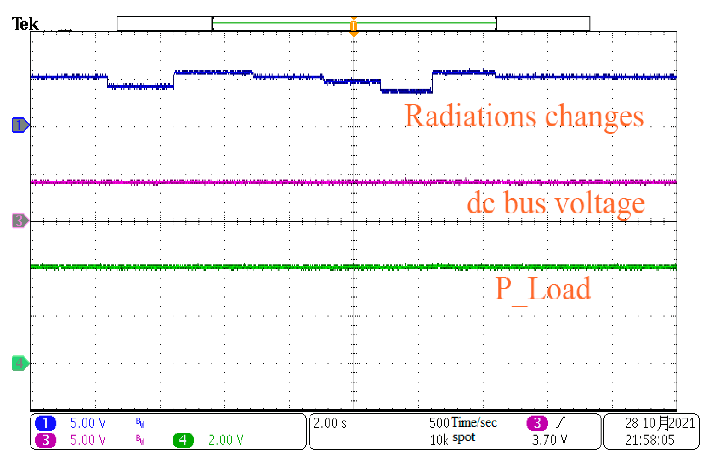
6.3. The Radiations Changes Scenarios with Constant Load

Another random radiations changes scenario (Figure 13a) is used to verify the control strategy’s robustness in Figure 13, Figure 14, Figure 15 and Figure 16. The PV arrays are exposed to the same but variable irradiation during this time. The DC-link voltage stays steady despite irradiance variations, with only minor fluctuations due to abrupt and violent radiation changes.
As demonstrated above, the control and power management system employing sliding mode control for hybrid PV/BES, with both DC and AC loads in standalone photovoltaic systems, is capable of managing power flows in the converters of all units flexibly and effectively, and ultimately achieving power balance between the hybrid microgrid system and the AC load. Additionally, DSMCs assures the system’s reliability of power supply when PV power fluctuates due to unpredictable irradiance and demand, or when the battery is unavailable. Additionally, this enables the system to accommodate higher loads without the need for additional converters, lowering operation and control expenses. Finally, the effort will seek to identify a viable DSMCs solution for stabilizing the DC-link voltage and minimizing power loss in photovoltaic production due to PV voltage ripple with a lowered DC-link capacitor in the DC-link voltage, as well as improving the overall system’s dynamic performance.

7. Hardware-in-the-Loop Experimental Results and Analysis

The experiment platform is created to validate the proposed sliding mode control method’s effectiveness. The control mechanism is implemented using the National Instruments PXIE-1071. As illustrated in Figure 17, the NI PXIE-1071 primarily performs hardware-in-the-loop simulation using HIL software. The system’s power circuit is implemented using an NI PXIE-1071 FPGA board. The sampling and control circuit is translated to C code using the NI standard C language code generation tool in Simulink and then loaded into the NI PXIE-1071 control board. The power analyzer displays the experimental findings via an external port board attached to a number of ports defined within the NI PXIE-1071.
To validate the suggested control scheme and model’s performance under various operating situations, and demonstrate the state of the different voltages, currents, power states, and harmonics of the system’s components, two alternative scenarios were constructed. The first displaying the system’s dynamics and control performance under varied load situations and the second showing the different partial shading conditions with constant load. The total harmonic distortion (THD) of the DC-link voltage capacitor has been removed, as illustrated in Figure 18. It is a very essential component of power quality related to grid rules as well as the load’s nominal frequency design. Even if the system is independent, providing high power quality to the user is critical.

7.1. The Experiment Results under Load Variation Scenario with Radiations Changes

The power, current, and voltage variations of various parts of the system during the experiment time under load fluctuation scenario with radiations changes are illustrated in the following curves (Figure 18, Figure 19, Figure 20 and Figure 21).

7.2. The Experiment Results under the Radiation Changes Scenarios with Constant Load

The experimental results in the above demonstrated the effectiveness of the proposed method and its influence on the stability of the system under the condition of load and radiation changes, as well as the good harmonic suppression performance (Figure 22, Figure 23, Figure 24 and Figure 25).

8. Conclusions

This study offered comprehensive modeling and a novel control strategy for PV/BES grid-connected system with both AC and DC loads. In a range of operating circumstances such as load and radiation changes, the dynamic performance of system is investigated. Reduced dc-link capacitance is shown to have an effect on the dynamic stability of the entire system via interactions with the solar array’s dynamic resistance. All possible scenarios were considered. Each controller in the system used direct sliding mode control to modify and stabilize the dc-link voltage while keeping the dc-link capacitance as low as possible. The duty cycle of the MPPT was determined using both the P&O and SMC methods. Without batteries, the concept of employing photovoltaic panels to control the dc-link voltage significantly improved the system. Additionally, the direct sliding mode control described here offers the following benefits: (1) It is effective and can be easily used to overcome the problems of using a small dc-link capacitor in the PV/BES grid-connected system, such as the output current ripples and overvoltage and undervoltage of the dc-link voltage; (2) it has no effect on the steady-state operation of the VSC grid-connected photovoltaic system; (3) it improves the dynamic performance of the dc-link voltage and provides robust and stable performance under a variety of photovoltaic system operating conditions and load variations, better than the PI controller; and (4) it allows for the transmission of low voltage ripples in a variety of operational conditions. Finally, the described control approaches ensure that the power balance between the various distributed resources in a PV/BES grid-connected system remains stable under extreme conditions. The operation of a low voltage a PV/BES grid-connected system is validated in various operating modes on the MT real-time control platform NI PXIE-1071 using Hardware-In-the-Loop experiments and Matlab/Simulink.

Author Contributions

Each of the four authors made an equal contribution. I.A.-W. was in charge of the analysis, while Z.F. was in charge of the introduction and literature review, and Z.W. and H.D. were in charge of the overall formatting of the paper. All authors have read and agreed to the published version of the manuscript.

Funding

This work was supported in part by the National Natural Science Foundation of China under Grants 51707138.

Data Availability Statement

All of the data in this report come from the Hubei Key Laboratory of Advanced Control and Intelligent Automation for Complex Systems in China University of Geosciences, Wuhan 430074, China.

Conflicts of Interest

The authors declare that they have no conflict of interest.

References

  1. Hansen, J.; Sato, M.; Ruedy, R.; Kharecha, P.; Lacis, A.; Miller, R.; Nazarenko, L.; Lo, K.; Schmidt, G.A.; Russell, G.; et al. Climate simulations for 1880–2003 with giss modele. Clim. Dyn. 2007, 29, 661–696. [Google Scholar] [CrossRef] [Green Version]
  2. Xue, X.; Pang, Y.; Landis, A.E. Evaluating agricultural management practices to improve the environmental footprint of corn-derived ethanol. Renew. Energy 2014, 66, 454–460. [Google Scholar] [CrossRef]
  3. Xiang-Li, L.; Zhi-Yong, R.; Lin, D. An investigation on life-cycle energy consumption and carbon emissions of building space heating and cooling systems. Renew. Energy 2015, 84, 124–129. [Google Scholar] [CrossRef]
  4. Atalay, Y.; Biermann, F.; Kalfagianni, A. Adoption of renewable energy technologies in oil-rich countries: Explaining policy variation in the gulf cooperation council states. Renew. Energy 2016, 85, 206–214. [Google Scholar] [CrossRef]
  5. Ahmed, S.; Islam, M.T.; Karim, M.A.; Karim, N.M. Exploitation of renewable energy for sustainable development and overcoming power crisis in Bangladesh. Renew. Energy 2014, 72, 223–235. [Google Scholar] [CrossRef]
  6. Rizzi, F.; van Eck, N.J.; Frey, M. The production of scientific knowledge on renewable energies: Worldwide trends, dynamics and challenges and implications for management. Renew. Energy 2014, 62, 657–671. [Google Scholar] [CrossRef]
  7. Polo López, C.S.; Lucchi, E.; Leonardi, E.; Durante, A.; Schmidt, A.; Curtis, R. Risk-Benefit Assessment Scheme for Renewable Solar Solutions in Traditional and Historic Buildings. Sustainability 2021, 13, 5246. [Google Scholar] [CrossRef]
  8. Standard EN 16883:2017. Conservation of Cultural Heritage. Guidelines for Improving the Energy Performance of Historic Buildings; Comitè Européen de Normalization (CEN): Bruxelles, Belgium, 2017. [Google Scholar]
  9. Yazdani, A.; Iravani, R. Voltage-Sourced Converters in Power Systems; John Wiley & Sons: Hoboken, NJ, USA, 2010; p. 39. [Google Scholar]
  10. Ahmed, N.A.; Al-Othman, A.K.; AlRashidi, M.R. Development of an efficient utility interactive combined wind/photovoltaic/fuel cell power system with MPPT and DC bus voltage regulation. Electr. Power Syst. Res. 2011, 81, 1096–1106. [Google Scholar] [CrossRef]
  11. Hajizadeh, A.; Golkar, M.A. Control of hybrid fuel cell/energy storage distributed generation system against voltage sag. Int. J. Electr. Power Energy Syst. 2010, 32, 488–497. [Google Scholar] [CrossRef]
  12. Tankari, M.A.; Camara, M.B.; Dakyo, B.; Nichita, C. Ultracapacitors and batteries integration for power fluctuations mitigation in wind-PV-diesel hybrid system. Int. J. Renew. Energy Res. 2011, 1, 86–95. [Google Scholar]
  13. Piepenbreier, B.; Sack, L. Regenerative drive converter with line-frequency switched rectifier and without DC link components. In Proceedings of the 2004 IEEE 35th Annual Power Electronics Specialists Conference, Aachen, Germany, 20–25 June 2004; Volume 5, pp. 3917–3923. [Google Scholar] [CrossRef]
  14. Sudhoff, S.D.; Corzine, K.A.; Glover, S.F.; Hegner, H.J.; Robey, H.N. DC link stabilized field oriented control of electric propulsion systems. IEEE Trans. Energy Convers. 1998, 13, 27–33. [Google Scholar] [CrossRef]
  15. Yarlagadda, S.K.; Shireen, W. A maximum power point tracking technique for single-phase PV systems with reduced DC-link capacitor. In Proceedings of the 2014 IEEE Applied Power Electronics Conference and Exposition-APEC, Fort Worth, TX, USA, 16–20 March 2014; pp. 2950–2957. [Google Scholar] [CrossRef]
  16. Khodabandeh, M.; Afshari, E.; Amirabadi, M. A Single-Stage Soft-Switching High-Frequency AC-Link PV Inverter: Design, Analysis, and Evaluation of Si-Based and SiC-Based Prototypes. IEEE Trans. Power Electron. 2018, 34, 2312–2326. [Google Scholar] [CrossRef]
  17. Afshari, E.; Khodabandeh, M.; Amirabadi, M. A single-stage capacitive AC-link AC–AC power converter. IEEE Trans. Power Electron. 2018, 34, 2104–2118. [Google Scholar] [CrossRef]
  18. Nousiainen, L.; Puukko, J.; Mäki, A.; Messo, T.; Huusari, J.; Jokipii, J.; Suntio, T. Photovoltaic generator as an input source for power electronic converters. IEEE Trans. Power Electron. 2012, 28, 3028–3038. [Google Scholar] [CrossRef]
  19. Messo, T.; Jokipii, J.; Puukko, J.; Suntio, T. Determining the value of DC-link capacitance to ensure stable operation of a three-phase photovoltaic inverter. IEEE Trans. Power Electron. 2013, 29, 665–673. [Google Scholar] [CrossRef]
  20. Sitbon, M.; Schacham, S.; Kuperman, A. Disturbance observer-based voltage regulation of current-mode-boost-converter-interfaced photovoltaic generator. IEEE Trans. Ind. Electron. 2015, 62, 5776–5785. [Google Scholar] [CrossRef]
  21. Magableh, M.A.K.; Radwan, A.; Mohamed, Y.A.R.I. Assessment and Mitigation of Dynamic Instabilities in Single-Stage Grid-Connected Photovoltaic Systems with Reduced DC-Link Capacitance. IEEE Access 2021, 9, 55522–55536. [Google Scholar] [CrossRef]
  22. Jackey, R.A. A simple, effective lead-acid battery modeling process for electrical system component selection. J. Passeng. Cars: Electron. Electr. Syst. 2007, 116, 219–227. [Google Scholar] [CrossRef] [Green Version]
  23. Petrík, T.; Daneček, M.; Uhlíř, I.; Poulek, V.; Libra, M. Distribution Grid Stability—Influence of Inertia Moment of Synchronous Machines. Appl. Sci. 2020, 10, 9075. [Google Scholar] [CrossRef]
  24. Libra, M.; Petrík, T.; Poulek, V.; Tyukhov, I.I.; Kouřím, P. Changes in the Efficiency of Photovoltaic Energy Conversion in Temperature Range with Extreme Limits. IEEE J. Photovolt. 2021, 11, 1479–1484. [Google Scholar] [CrossRef]
  25. Singh, S.; Fulwani, D.; Kumar, V. Robust sliding-mode control of dc/dc boost converter feeding a constant power load. IET Power Electron. 2015, 8, 1230–1237. [Google Scholar] [CrossRef]
  26. Yang, Z.; Zha, X.; Sun, J.; Liu, F. Global stabilization based on feedback linearization for DC microgrid. Electr. Power Autom. Equip. 2015, 35, 10–14. [Google Scholar] [CrossRef]
  27. Cucuzzella, M.; Incremona, G.P.; Ferrara, A. Design of robust higher order sliding mode control for microgrids. IEEE J. Emerg. Sel. Top. Circuits Syst. 2015, 5, 393–401. [Google Scholar] [CrossRef] [Green Version]
  28. Gudey, S.K.; Gupta, R. Recursive fast terminal sliding mode control in voltage source inverter for a low-voltage microgrid system. IET Gener. Transm. Distrib. 2016, 10, 1536–1543. [Google Scholar] [CrossRef]
  29. Tahim, A.P.; Pagano, D.J.; Ponce, E. Nonlinear control of dc-dc bidirectional converters in stand-alone dc microgrids. In Proceedings of the 2012 IEEE 51st IEEE Conference on Decision and Control (CDC), Maui, HI, USA, 10–13 December 2012; pp. 3068–3073. [Google Scholar] [CrossRef]
  30. Benadero, L.; Cristiano, R.; Pagano, D.J.; Ponce, E. Nonlinear analysis of interconnected power converters: A case study. IEEE J. Emerg. Sel. Top. Circuits Syst. 2015, 5, 326–335. [Google Scholar] [CrossRef] [Green Version]
  31. Su, X.; Han, M.; Sun, H. Stability control strategy for microgrid based on adaptive total sliding-mode Control. Proc. CSEE 2014, 34, 5534–5541. [Google Scholar] [CrossRef]
  32. Bahraini, F.; Abrishamifar, A.; Ayatollahi, A. Fast DC Bus Voltage Regulation for a Low Cost Single-Phase Grid-Connected PV Microinverter with a Small DC Bus Capacitor. In Proceedings of the 2020 11th Power Electronics, Drive Systems, and Technologies Conference (PEDSTC), Tehran, Iran, 4–6 February 2020; pp. 1–6. [Google Scholar] [CrossRef]
  33. Karlsson, P.; Svensson, J. DC bus voltage control for a distributed power system. IEEE Trans. Power Electron. 2003, 18, 1405–1412. [Google Scholar] [CrossRef] [Green Version]
  34. Xu, L.; Chen, D. Control and operation of a DC microgrid with variable generation and energy storage. IEEE Trans. Power Deliv. 2011, 26, 2513–2522. [Google Scholar] [CrossRef]
  35. Sun, K.; Zhang, L.; Xing, Y.; Guerrero, J.M. A distributed control strategy based on DC bus signaling for modular photovoltaic generation systems with battery energy storage. IEEE Trans. Power Electron. 2011, 26, 3032–3045. [Google Scholar] [CrossRef] [Green Version]
  36. Zhang, L.; Sun, K.; Xing, Y.; Feng, L.; Ge, H. A modular grid-connected photovoltaic generation system based on DC bus. IEEE Trans. Power Electron. 2011, 26, 523–531. [Google Scholar] [CrossRef]
  37. Bhat, S.; Nagaraja, H.N. DSP based proportional integral sliding mode controller for photo-voltaic system. Electr. Power Energy Syst. 2015, 71, 123–130. [Google Scholar] [CrossRef]
  38. Thang, T.V.; Ahmed, A.; Kim, C.-I.; Park, J.-H. Flexible system architecture of stand-alone pv power generation with energy storage device. IEEE Trans. Energy Convers 2015, 30, 1386–1396. [Google Scholar] [CrossRef]
  39. Fardoun, A.A.; Ismail, E.H.; Sabzali, A.J.; Al-Saffar, M.A. Bidirectional converter for high-efficiency fuel cell powertrain. J. Power Sources 2014, 249, 470–482. [Google Scholar] [CrossRef]
  40. Ahmed, O.A.; Bleijs, J.A.M. Power flow control methods for an ultra-capacitor bidirectional converter in dc microgrids—A comparative study. Renew. Sustain. Energy Rev. 2013, 26, 727–738. [Google Scholar] [CrossRef]
  41. Tsang, K.M.; Chan, W.L. Model based rapid maximum power point tracking for photovoltaic. Energy Convers. Manag. 2013, 70, 83–89. [Google Scholar] [CrossRef]
  42. Rajesh, R.; CarolinMabel, M. A comprehensive review of photovoltaic systems. Renew. Sustain. Energy Rev. 2015, 51, 231–248. [Google Scholar] [CrossRef]
  43. Zhou, Z.; Holland, P.M.; Igic, P. MPPT algorithm test on a photovoltaic emulating system constructed by a dc power supply and an indoor solar panel. Energy Convers. Manag. 2014, 85, 460–469. [Google Scholar] [CrossRef]
  44. Dragičević, T.; Guerrero, J.M.; Vasquez, J.C.; Škrlec, D. Supervisory control of an adaptive-droop regulated dc microgrid with battery management capability. IEEE Trans. Power Electron. 2014, 29, 695–706. [Google Scholar] [CrossRef] [Green Version]
Figure 1. System configuration/control of the grid connected PV/BES with local AC and DC loads.
Electronics 11 00133 g001
Figure 2. One phase-two stage PV DC-link capacitor power conditioner.
Electronics 11 00133 g002
Figure 3. The control of the bidirectional converter (BDC).
Electronics 11 00133 g003
Figure 4. Structure of the bidirectional DC-DC converter.
Electronics 11 00133 g004
Figure 5. BDC controllers.
Electronics 11 00133 g005
Figure 6. DC boost converter model.
Electronics 11 00133 g006
Figure 7. Cascaded PV boost converter control.
Electronics 11 00133 g007
Figure 8. DSMCs and P&O algorithm of the PV boost converters.
Electronics 11 00133 g008
Figure 9. Current load, AC load output under load and radiation changes. (a) The load current curve. (b,c) AC load time.
Electronics 11 00133 g009
Figure 10. The DC-link voltage output under load and radiation changes.
Electronics 11 00133 g010
Figure 11. Changes in the first PV array’s current, voltage, and power under load and radiation changes.
Electronics 11 00133 g011
Figure 12. Changes in the battery’s current, voltage, and power under load and radiation changes.
Electronics 11 00133 g012
Figure 13. Current load, AC load output under load constant, and radiation changes. (a) The load current, (b,c) AC load time.
Electronics 11 00133 g013
Figure 14. DC-link voltage output under load constant and radiation changes.
Electronics 11 00133 g014
Figure 15. Changes in the first PV array’s current, voltage, and power under load constant and radiation changes.
Electronics 11 00133 g015
Figure 16. Changes in the battery’s current, voltage, and power under load constant and radiation changes.
Electronics 11 00133 g016
Figure 17. Hardware-in-the-loop experiment hardware configuration.
Electronics 11 00133 g017
Figure 18. Current, power load, and the DC-link voltage output current, voltage, and power under load and radiation changes; (月 is month).
Electronics 11 00133 g018
Figure 19. The first PV array’s current, voltage, and power under load and radiation changes.
Electronics 11 00133 g019
Figure 20. The battery’s current, voltage, and power under load and radiation changes.
Electronics 11 00133 g020
Figure 21. AC loads output under load variation and radiation changes; (月 is month).
Electronics 11 00133 g021
Figure 22. The radiations scenario, power load, and the DC-link voltage output under constant load and radiation changes; (月 is month).
Electronics 11 00133 g022
Figure 23. The first PV array’s current, voltage, and power under load constant and radiation changes; (月 is month).
Electronics 11 00133 g023
Figure 24. The battery’s current, voltage, and power under load constant and radiation changes; (月 is month).
Electronics 11 00133 g024
Figure 25. AC loads output under constant load and radiation changes; (月 is month).
Electronics 11 00133 g025
Publisher’s Note: MDPI stays neutral with regard to jurisdictional claims in published maps and institutional affiliations.

