
Analysis of ATO System Operation Scenarios Based on UPPAAL and the Operational Design Domain


Abstract
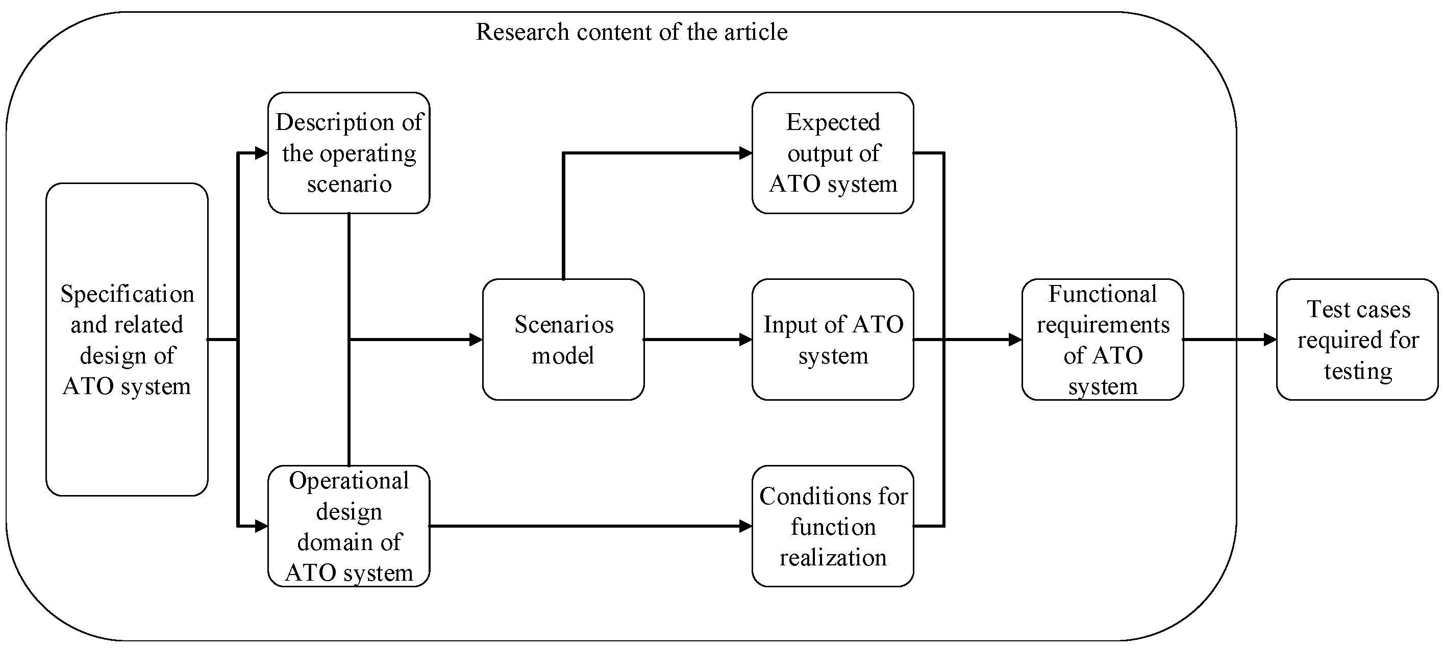
:1. Introduction
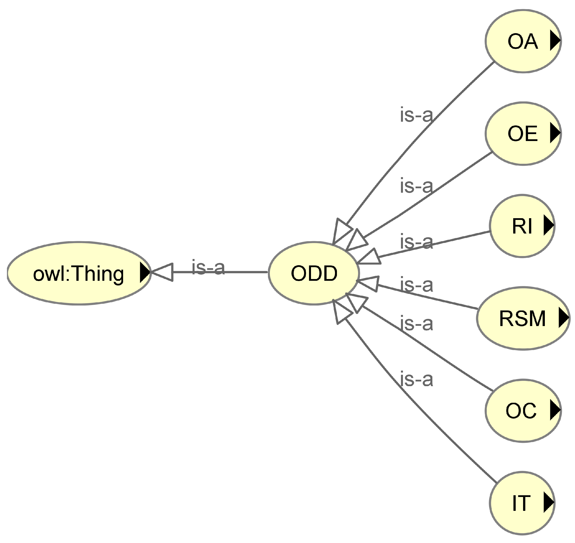
2. Operational Design Domain of the High-Speed Railway ATO System
2.1. Introduction to the Operational Design Domain
- Design process: Defining the ODD helps identify what scenarios the automated driving system must handle. System-wide and system requirements can then be defined alongside the ODD.
- Testing and verification: The ODD can be sampled to generate test cases with varying levels of detail for unit testing or integration testing via simulation.
- Online monitoring: The ODD can be instantiated as a runtime object to be measured and validated during operation. This is also known as functional boundary monitoring [15].
2.2. System Operation Characteristics
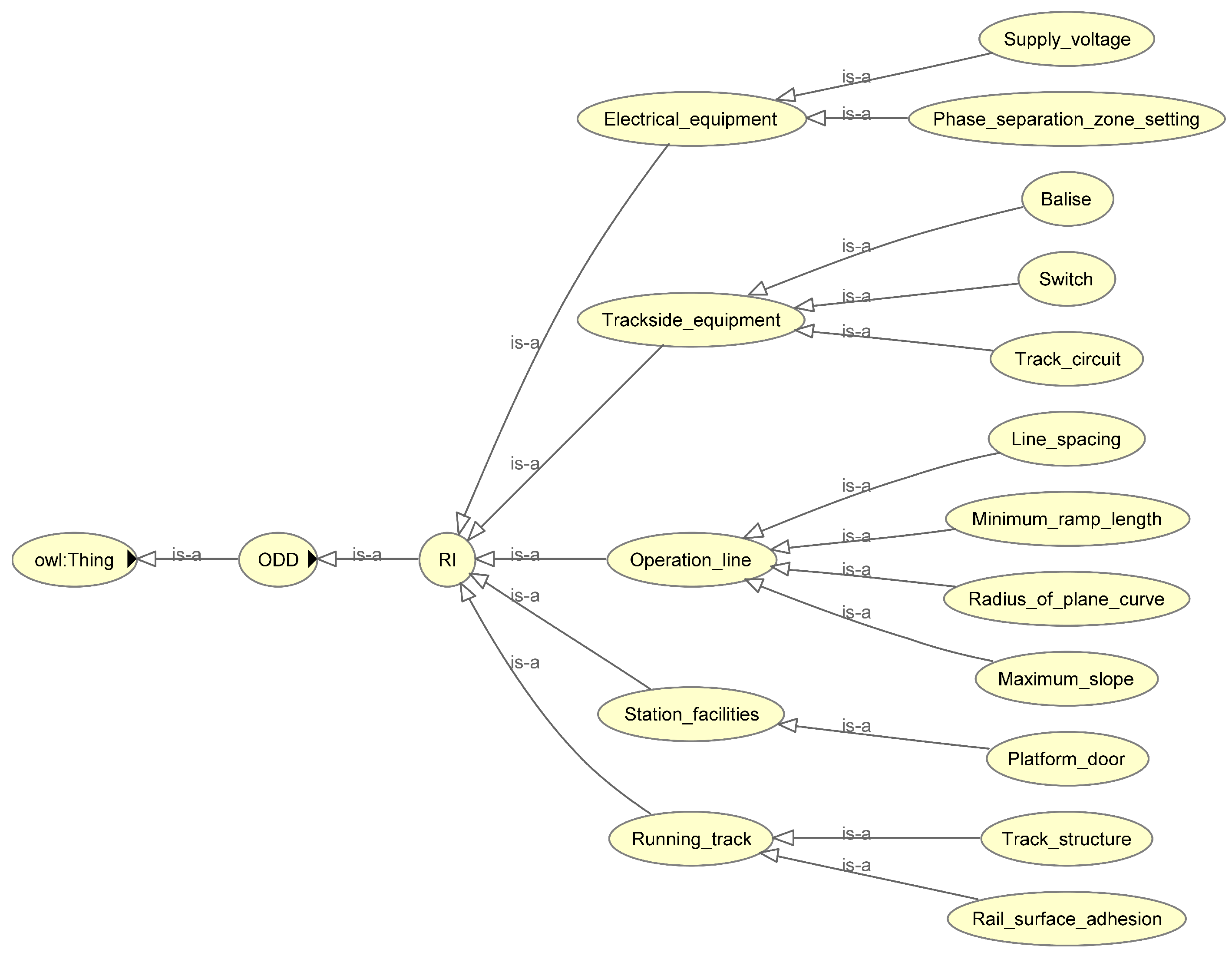
- The terrain of China is complicated, and ramps, bends, and tunnels were built according to the terrain during the construction of the running track. For high-speed railways, generally, the maximum gradient is not allowed to be greater than 20‰, and the difficult areas are no greater than 30‰. Steel track-carrying trains are used to run mainly ballastless tracks, and the standard gauge is usually 1435 mm.
- Through the construction of various facilities, many stations have been established along the railway for passengers to get on and off. Some stations are equipped with platform screen doors. At the same time, turnouts are set to guide trains into different platform lanes.
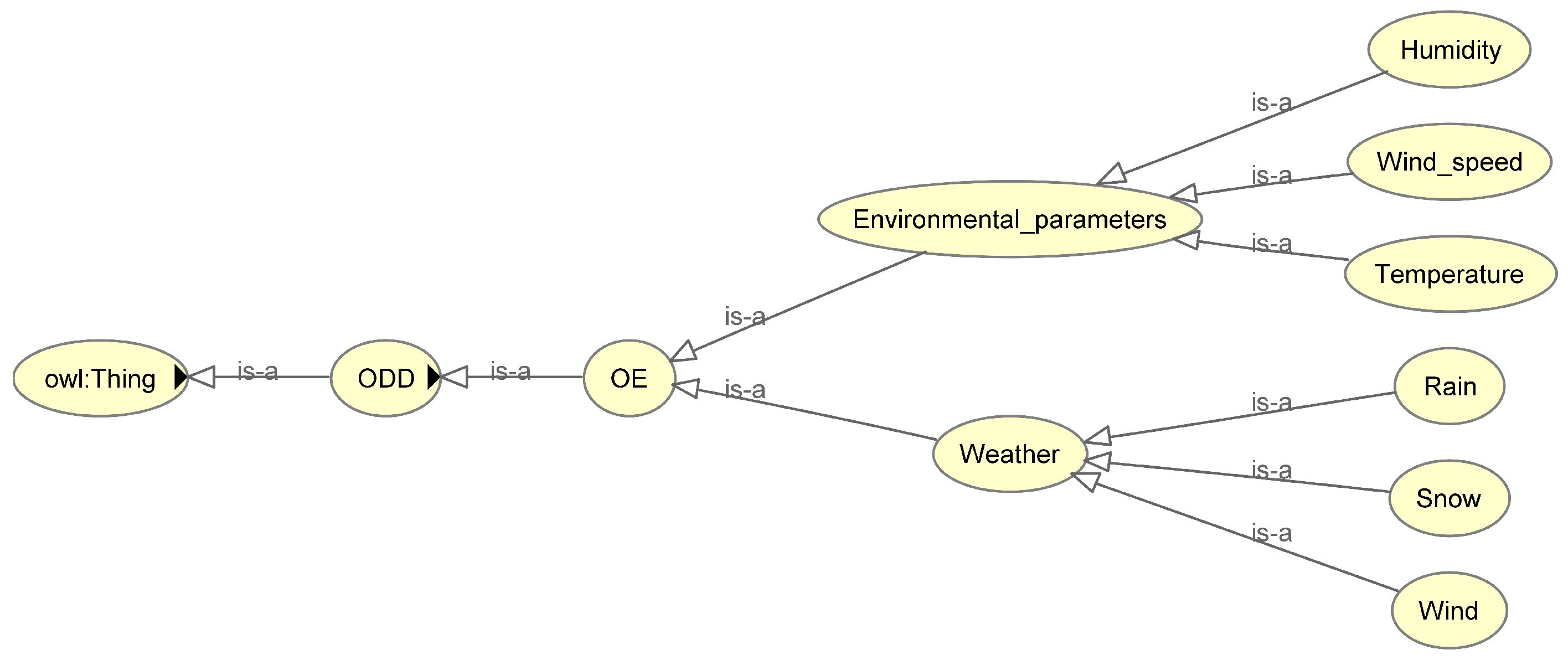
- The operation of the system has its normal temperature, humidity, wind speed, and other environmental requirements. In extreme weather such as strong winds, severe rain, and snow, the operation of the system will be restricted.
- System operation has a boundary: the maximum speed is limited to 350 km/h; the speed in the ceiling speed zone is no less than 80 km/h; and the track the train enters at the station is restricted by the operation plan. The system’s information interaction has a maximum response time. The response time is regarded as a communication timeout. The constraints in operation are also the basis for judging the normal operation of the system.
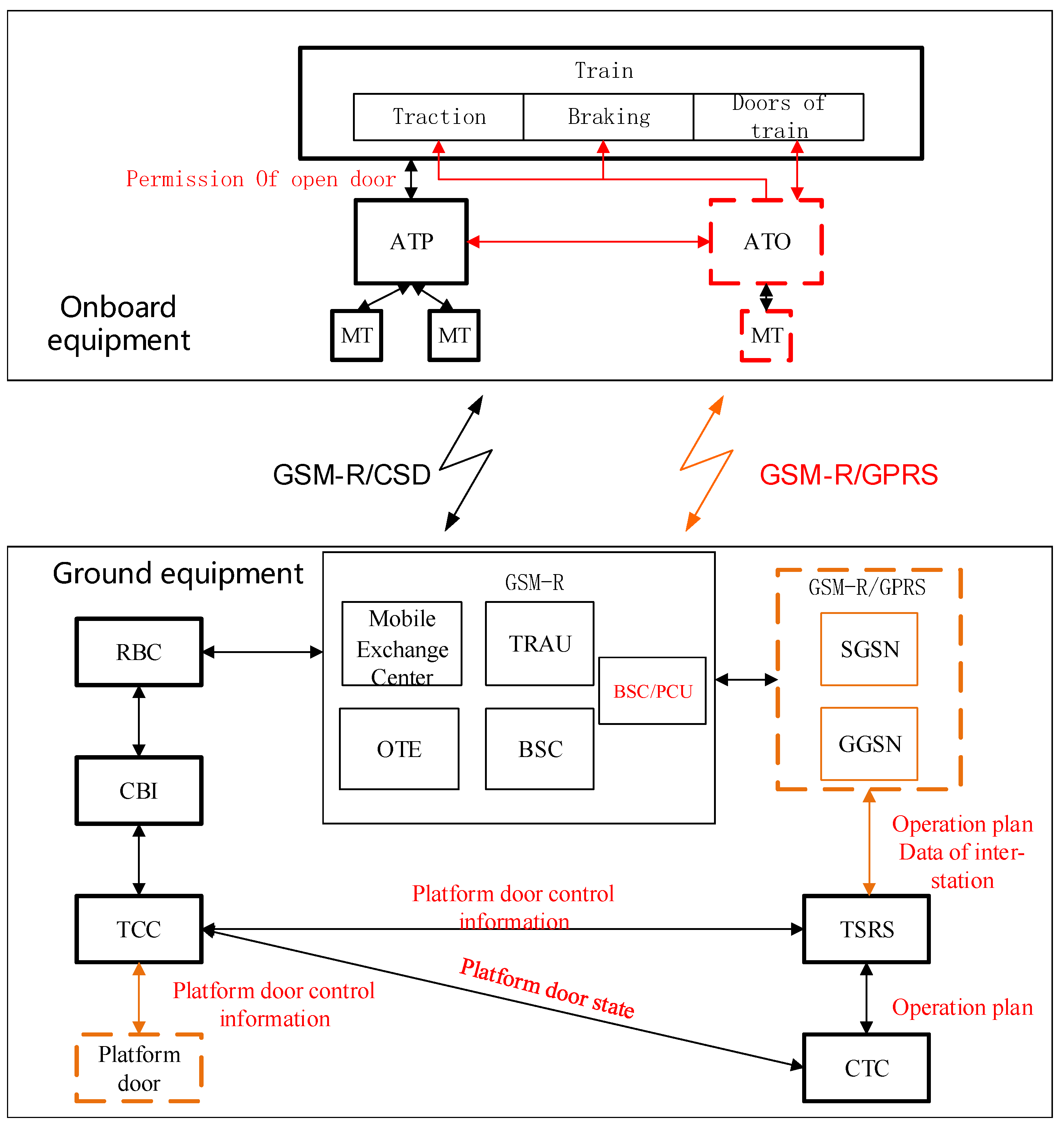
- The high-speed railway ATO system is based on the CTCS-2/CTCS-3 level train control system. The train is equipped with an ATO unit to realize automatic driving control, and a dedicated precision positioning transponder is installed on the ground to achieve special positioning. The ground equipment communicates via GPRS (General Packet Radio Service) to realize platform door control, data transmission between stations, and train operation adjustment plan (referred to as the operation plan) processing.
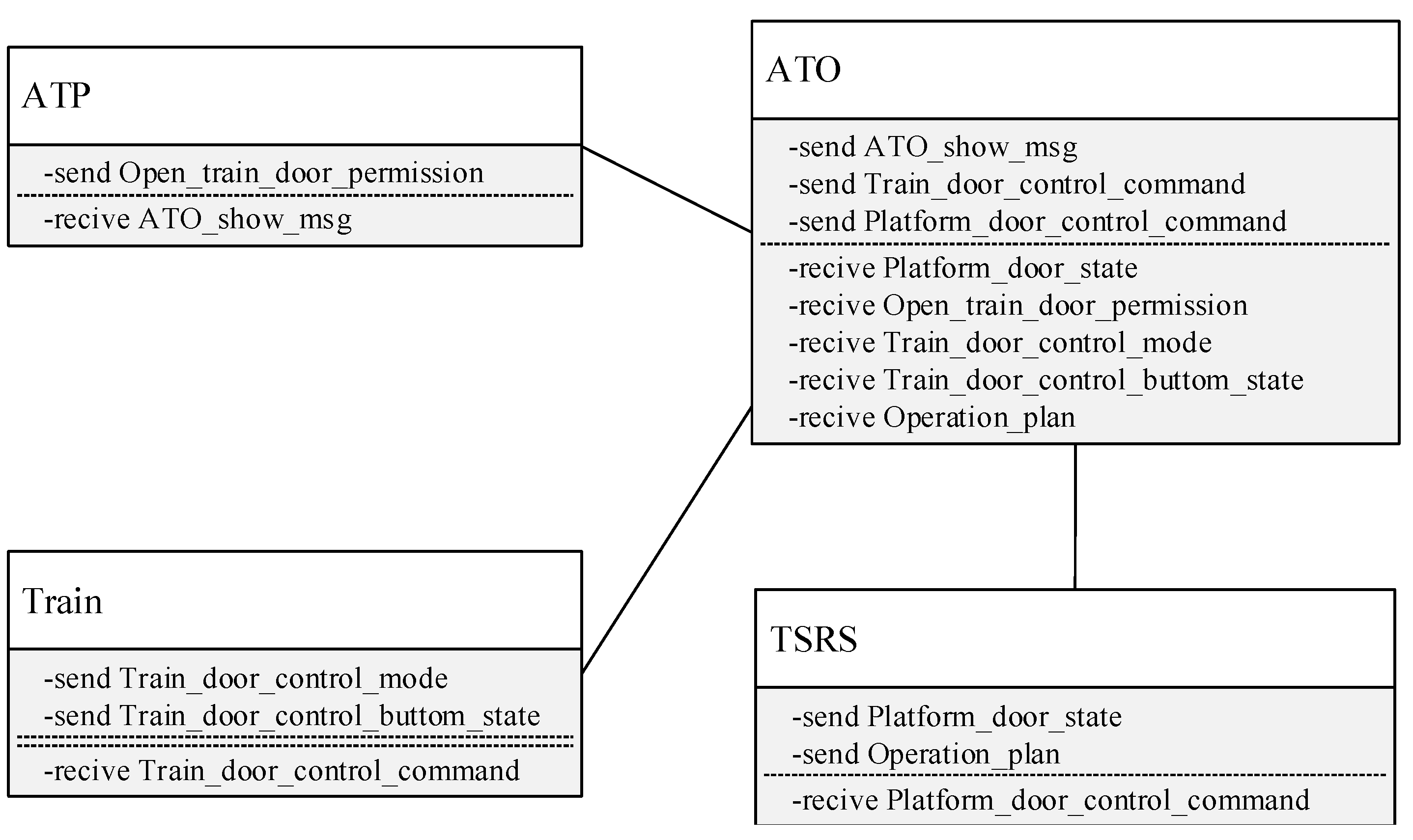
2.3. Structure and Interface of the High-Speed Railway ATO System
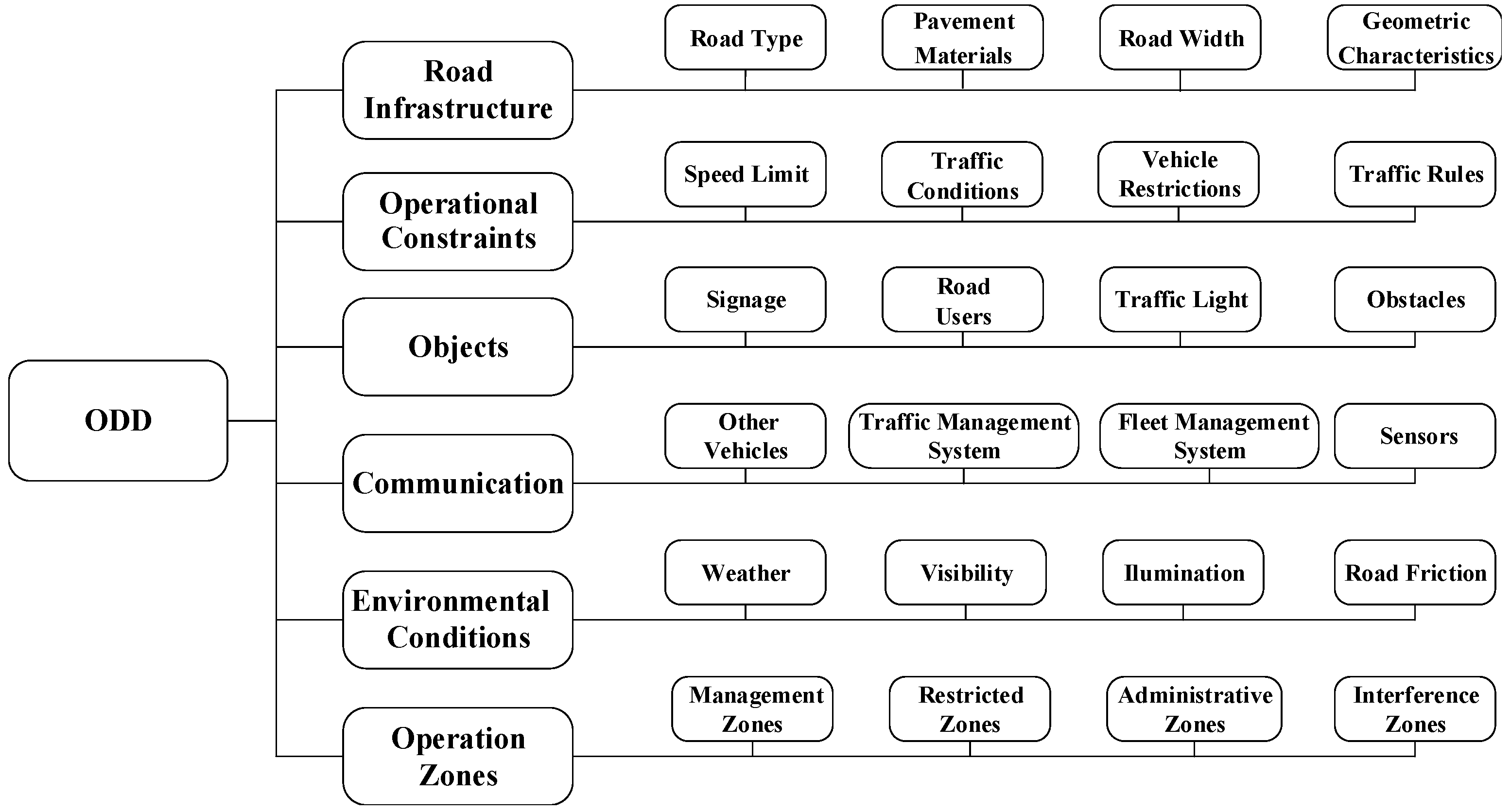
2.4. Operational Design Domain of ATO System Members
2.4.1. Railway Infrastructure
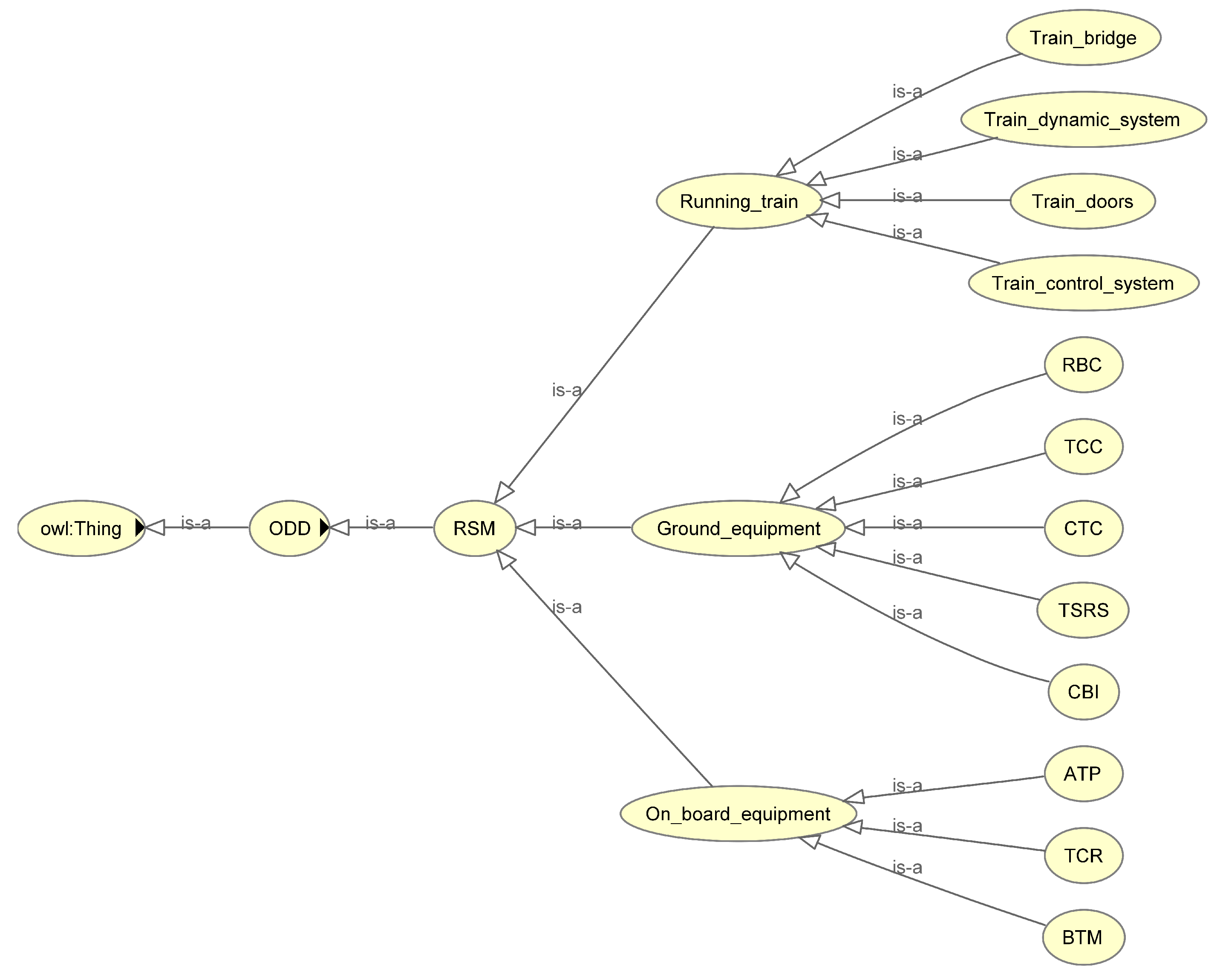
2.4.2. Related System Members
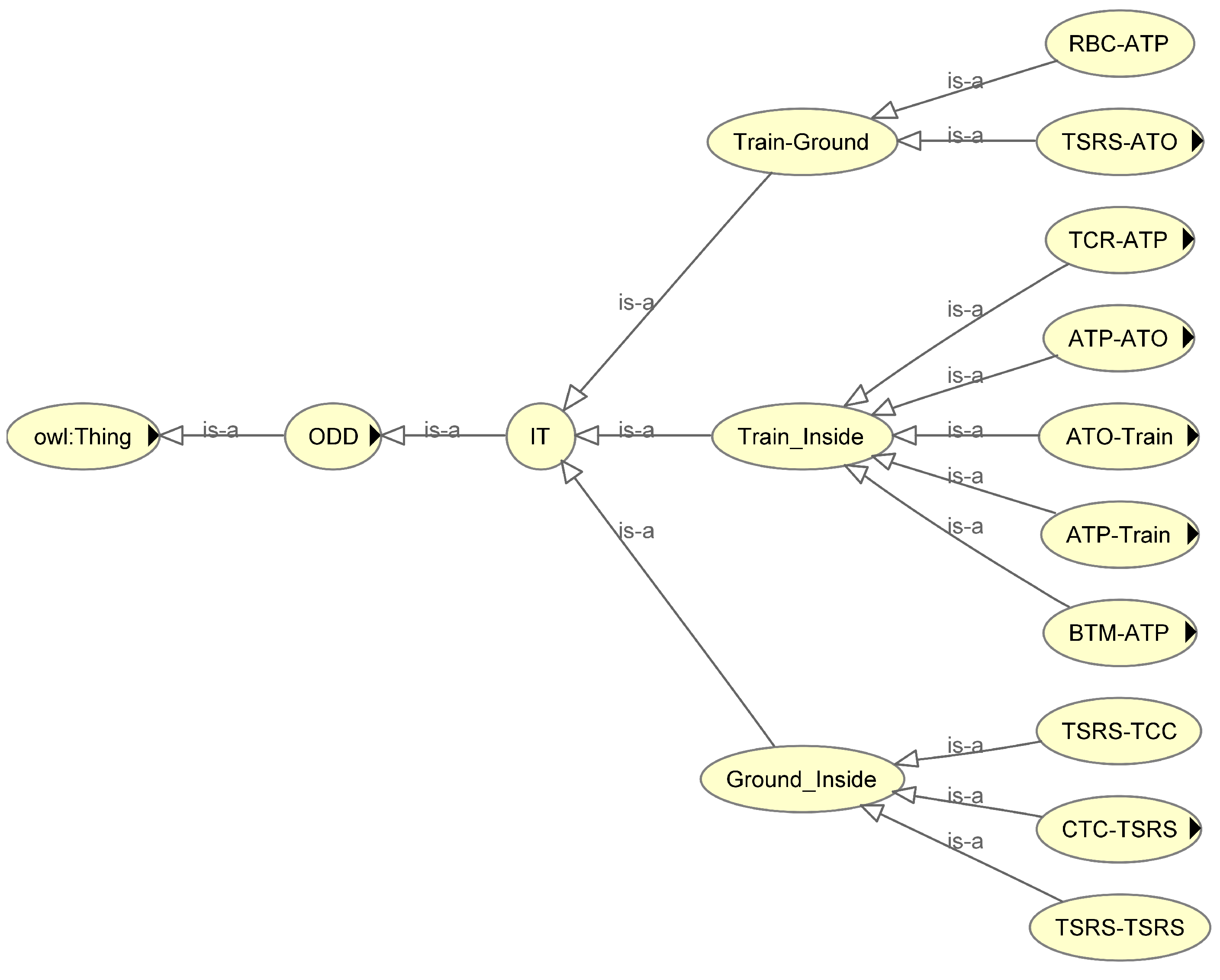
2.4.3. Information Transmission
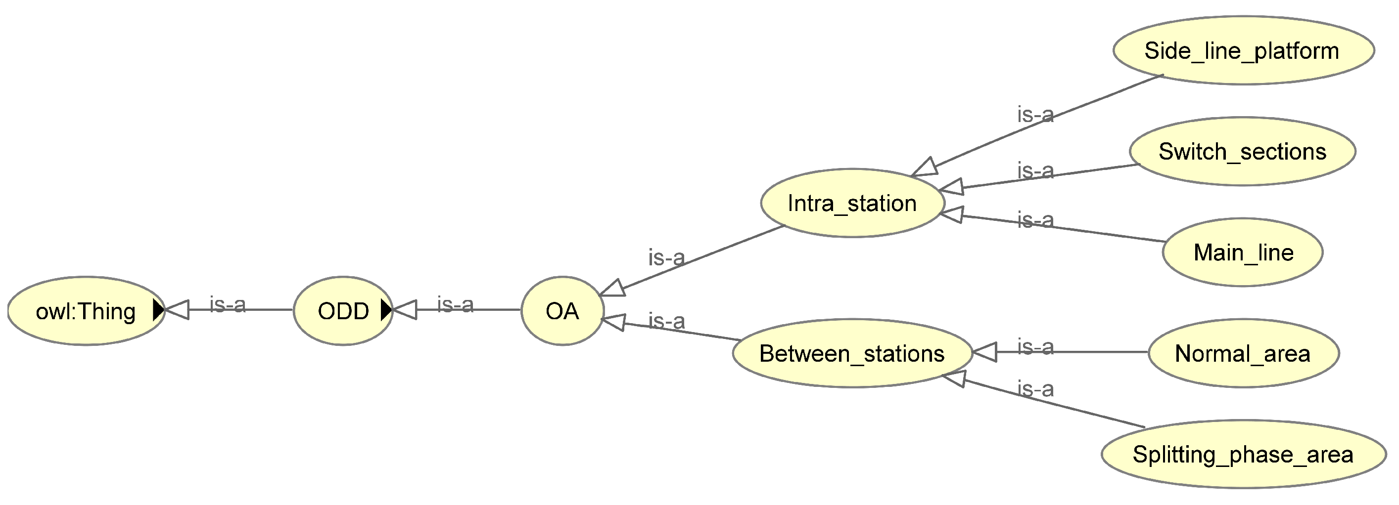
2.4.4. Operating Area
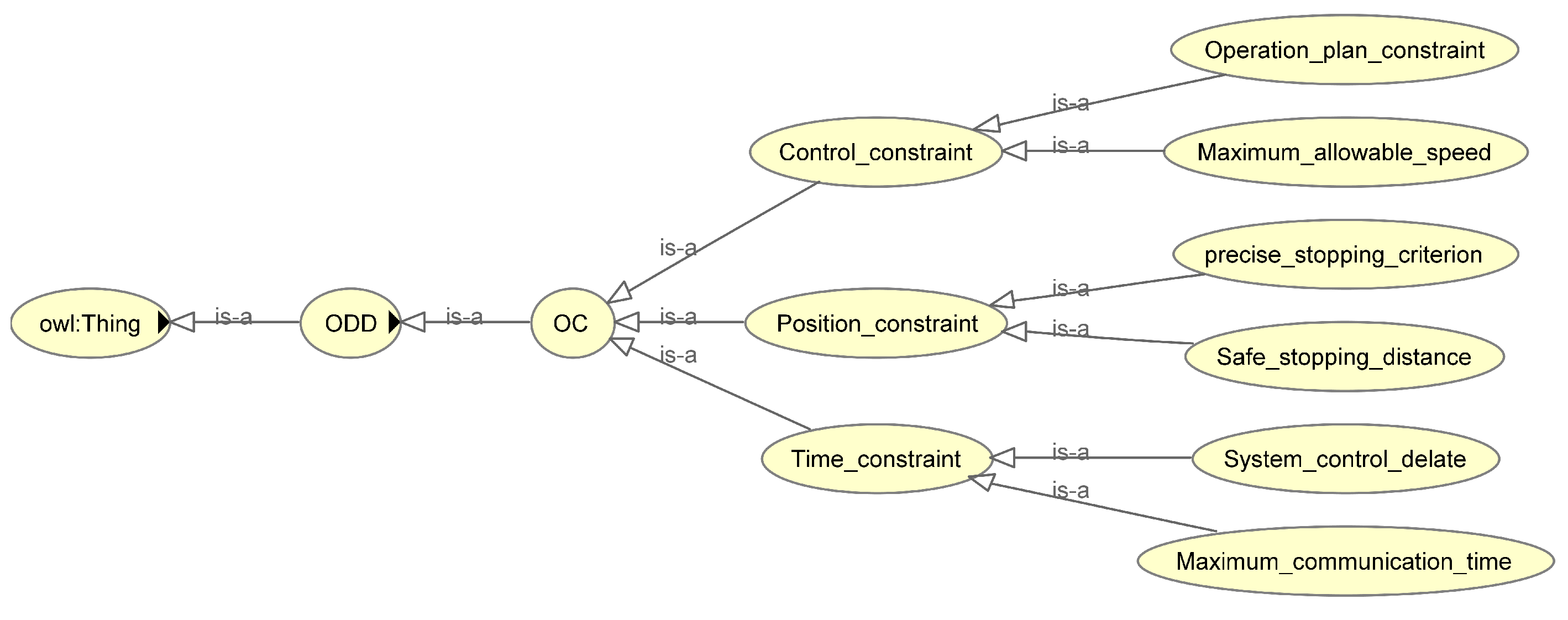
2.4.5. Operational Constraints
2.4.6. Operating Environment
3. Timed Automata and the UPPAAL Tool
3.1. Introduction to Timed Automata
- Q means a limited set of positions; is the initial position.
- E means a limited set of observable behaviors.
- X represents a limited set of clock variables.
- I means the mapping from position to position invariant.
- T means a finite set of integer variables.
- Y means a set of transitions.
3.2. Introduction to the Verification Tool UPPAAL
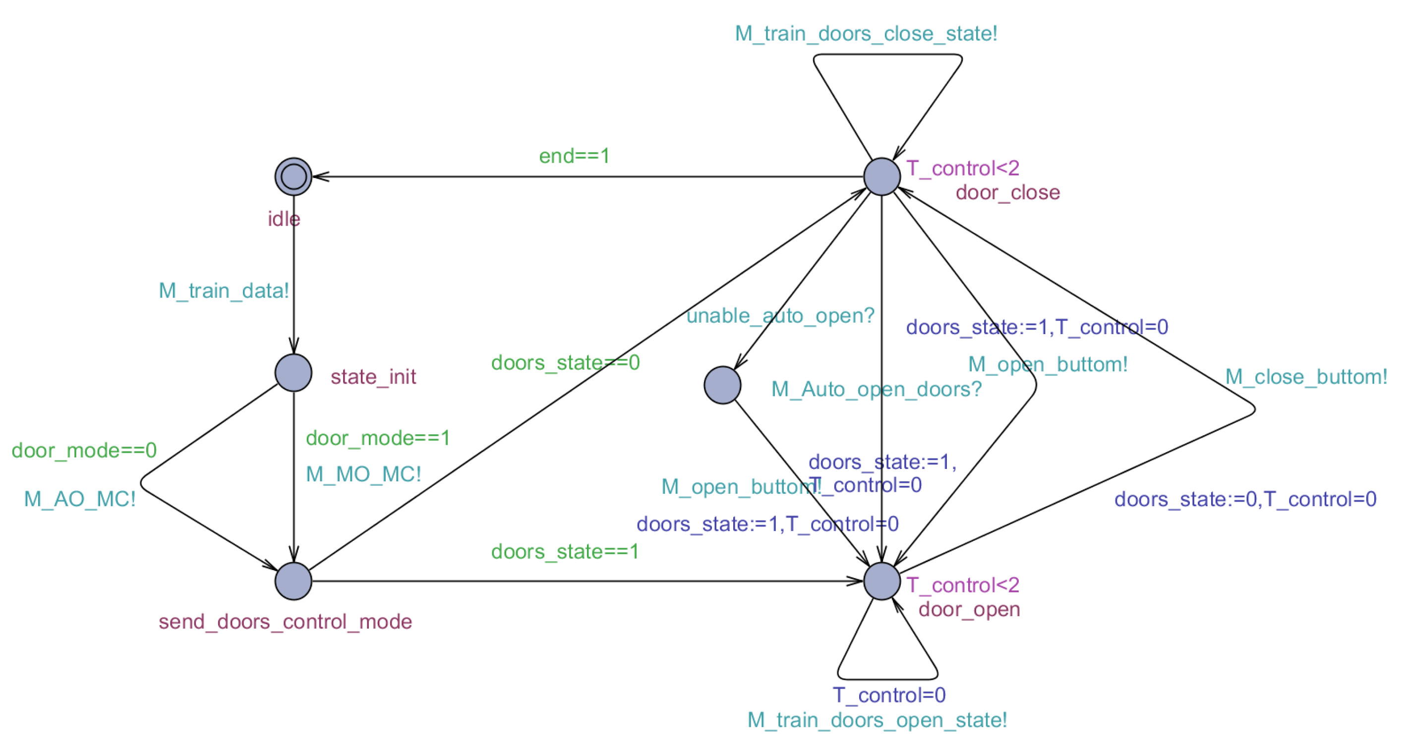
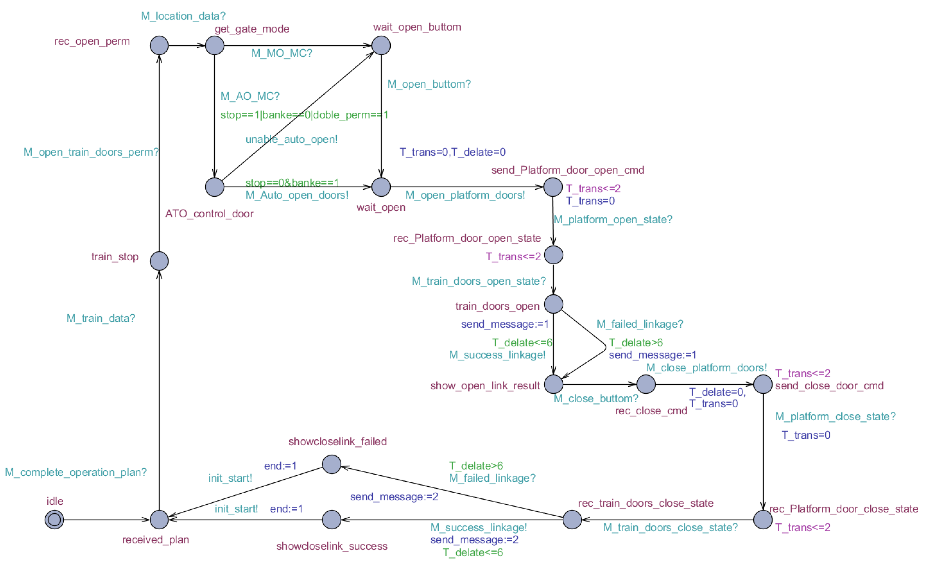
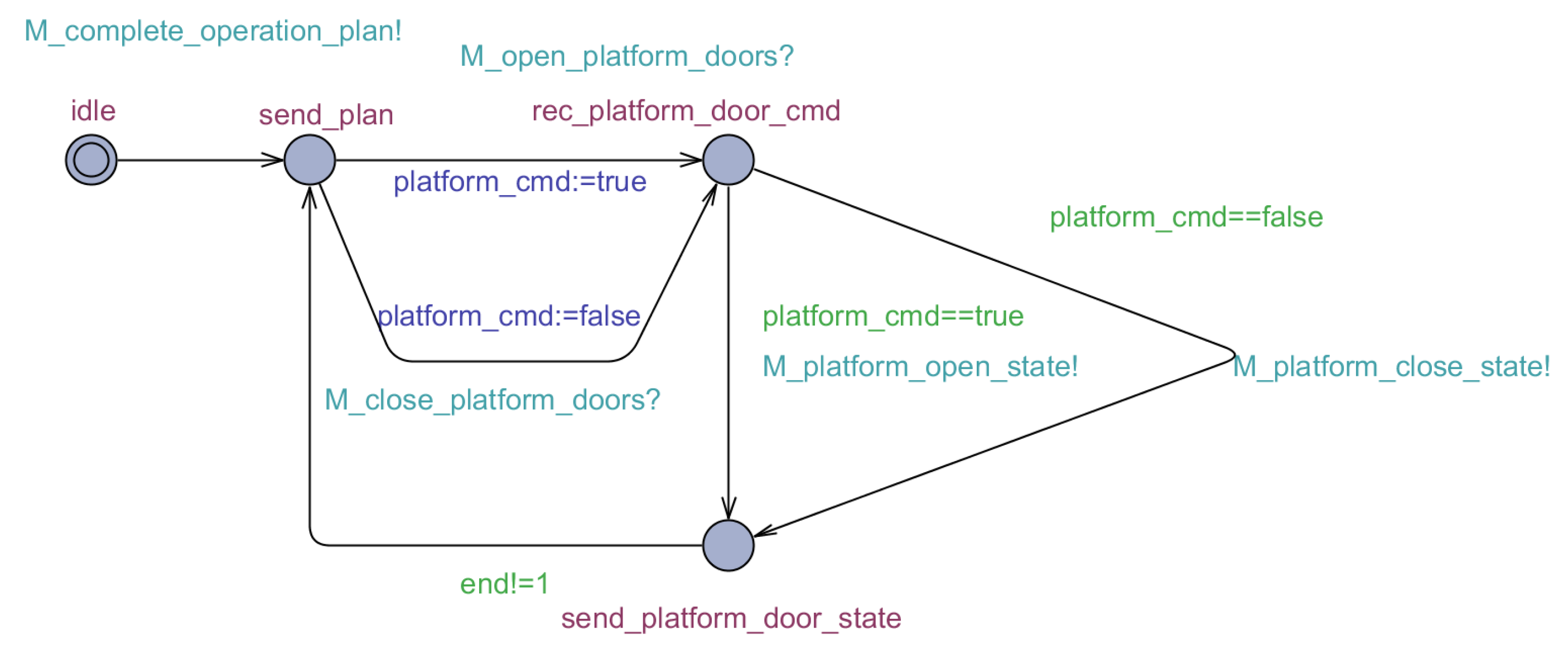
4. Case Study
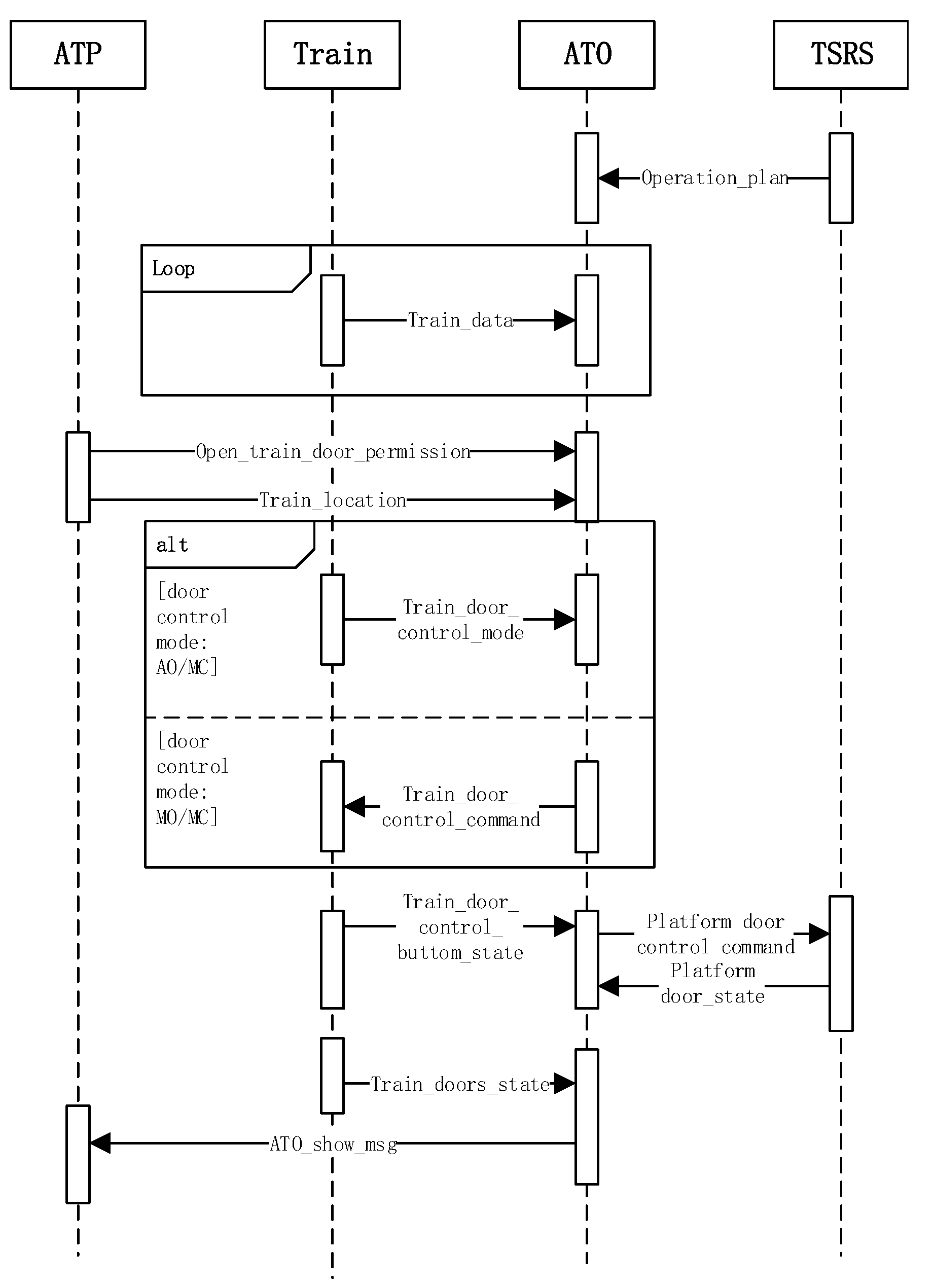
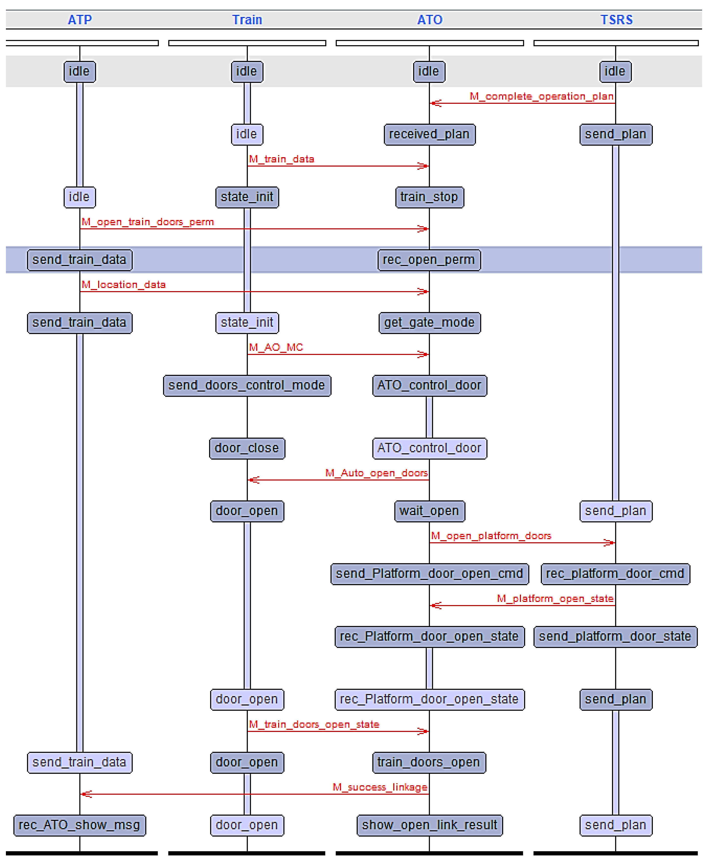
4.1. Scenario Description and Analysis
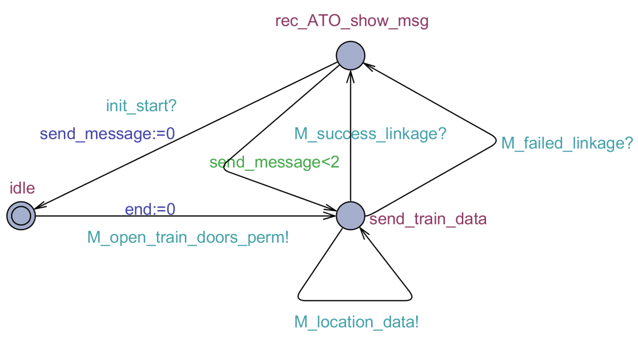
4.2. Scenario Model Construction
4.3. Verification of the Scenario
4.3.1. Performing Verification Dynamically
4.3.2. Property Verification
4.4. Demand Extraction
- In the door control mode AO/MO, the onboard ATO can automatically open the door according to the plan when the sideline platform has the condition of stopping.
- In the AM mode, the onboard ATO can send correct platform door control commands to the TSRS based on the planning and marshalling information and the status of the door buttons.
5. Conclusions and Future Work
Author Contributions
Funding
Acknowledgments
Conflicts of Interest
Abbreviations
| ODD | Operational design domain |
| ATO | Automatic train operation |
| CTCS | Chinese train control system |
| GPRS | General packet radio service |
| TSRS | Temporary speed restriction server |
| CTC | Centralized traffic control |
| TCC | Train control center |
| ATP | Automatic train protection |
| RBC | Radio block center |
| BTM | Balise transmission module |
| TCR | Track circuit reader |
| MT | Mobile terminal |
| CBI | Computer based interlocking |
| OTE | Optical transmission equipment |
| TRAU | Transcoder and rate adaptor unit |
| BSC | Base station controller |
| PCU | Process control unit |
| SGSN | Serving GPRS support node |
| GGSN | Gateway GPRS support node. |
| TA | Timed automata |
| BNF | Backus Normal Form |
| SAE | Society of Automotive Engineers |
| AO | Automatic opening doors |
| MC | Manual closing doors |
| MO | manual opening doors |
| AM | Automatic driving mode |
| DMI | Driver machine interface |
References
- Liu, S.; Cao, F.; Xun, J.; Wang, Y. Energy-Efficient Operation of Single Train Based on the Control Strategy of ATO. In Proceedings of the 2015 18th International Conference on Intelligent Transportation Systems (ITSC), Gran Canaria, Spain, 15–18 September 2015; pp. 2580–2586. [Google Scholar] [CrossRef]
- Wang, L.; Xia, L.; Ye, H.; Jiang, M.; Wang, J.; Wang, Y. A Fast Optimization Method for Automatic Train Stop Control. In Proceedings of the 2019 15th International Conference on Control and Automation(ICCA), Edinburgh, UK, 16–19 July 2019; pp. 1405–1410. [Google Scholar] [CrossRef]
- Yang, Y.; Xu, Z.; Liu, W.; Li, H.; Zhang, R.; Huang, Z. Optimal Operation of High-Speed Trains Using Hybrid Model Predictive Control. J. Adv. Transp. 2018, 16, 1–16. [Google Scholar] [CrossRef] [Green Version]
- Kong, X.; Zhang, T. Non-Singular Fast Terminal Sliding Mode Control of High-Speed Train Network System Based on Improved Particle Swarm Optimization Algorithm. Symmetry 2020, 12, 205. [Google Scholar] [CrossRef] [Green Version]
- Cao, Y.; Ma, L.; Zhang, Y. Application of fuzzy predictive control technology in automatic train operation. Clust. Comput. 2018, 22, 14135–14144. [Google Scholar] [CrossRef]
- Yan, F.; Tang, T.; Yan, H. Scenario based STPA analysis in Automated Urban Guided Transport system. In Proceedings of the 2016 IEEE International Conference on Intelligent Rail Transportation (ICIRT), Birmingham, UK, 23–25 August 2016; pp. 425–431. [Google Scholar] [CrossRef]
- Zhang, Z.; Li, K.; Yuan, L.; Yu, G. Mutation Model-Based Test Case Generation of Chinese Train Control System with Automatic Train Operation Function. In Proceedings of the 2018 IEEE International Conference on Intelligent Rail Transportation (ICIRT), Singapore, 12–14 December 2018; pp. 1–5. [Google Scholar] [CrossRef]
- John, M.C.; Mary, B.R.; George, C.J.; Jürgen, K. Requirements Development in Scenario-Based Design. Trans. Software Eng. 1998, 24, 1156–1170. [Google Scholar] [CrossRef]
- Bindschadler, D.; Boyles, C. A Scenario-Based Process for Requirements Development: Application to Mission Operations Systems. In Proceedings of the 2008 SpaceOps Conference, Heidelberg, Germany, 12–16 May 2008; p. 3516. [Google Scholar]
- Daniel, A.; Gursimran, S.W.; Hyunsook, D.; Seok-Won, L. Model-based requirements verification method: Conclusions from two controlled experiments. Inf. Softw. Technol. 2014, 56, 321–334. [Google Scholar] [CrossRef] [Green Version]
- Yang, L.; Emitza, G.; Konstantina, T.; Florian, S.; Bernd, B. Automated Requirements Extraction for Scientific Software. In Proceedings of the 2015 International Conference on Computational Science(ICCS), Reykjavik, Iceland, 1–3 June 2015; pp. 582–591. [Google Scholar] [CrossRef] [Green Version]
- Michel, D.S.S.; Jos, L.M.V. Model-Driven User Requirements Specification using SysML. J. Softw. 2008, 3, 57–68. [Google Scholar] [CrossRef]
- Reggio, G. A UML-Based Proposalfor IoT System Requirements Specification. In Proceedings of the 10th International Workshop on Modelling in Software Engineering (MiSE), Gothenburg, Sweden, 22–30 May 2018; pp. 9–16. [Google Scholar] [CrossRef]
- Ian, C.; Buu, P.; Shahwar, S.; Rick, S.; Krzysztof, C. An Automated Vehicle Safety Concept Based on Runtime Restriction of the Operational Design Domain. In Proceedings of the 2018 IEEE Intelligent Vehicles Symposium (IV), Suzhou, China, 26–30 June 2018; pp. 1910–1917. [Google Scholar] [CrossRef]
- Markus, H.; Karl-Heinz, S. Strategy and architecture of a safety concept for fully automatic and autonomous driving assistance systems. In Proceedings of the 2010 IEEE Intelligent Vehicles Symposium (IV), La Jolla, CA, USA, 21–24 June 2010; pp. 955–960. [Google Scholar] [CrossRef]
- Thorn, E.; Kimmel, S.C.; Chaka, M.; Hamilton, B.A. A Framework for Automated Driving System Testable Cases and Scenarios. Available online: https://rosap.ntl.bts.gov/view/dot/38824 (accessed on 1 September 2018).
- Abramov, I.V.; Nikitin, Y.R.; Abramov, A.I.; Sosnovich, E.V.; Božek, P. Control and diagnostic model of brushless DC motor. J. Electr. Eng. 2014, 65, 277–282. [Google Scholar] [CrossRef] [Green Version]
- Božek, P.; Turygin, Y. Measurement of the Operating Parameters and Numerical Analysis of the Mechanical Subsystem. Meas. Sci. Rev. 2014, 14, 198–203. [Google Scholar] [CrossRef] [Green Version]
- Blatnický, M.; Sága, M.; Dižo, J.; Bruna, M. Application of Light Metal Alloy EN AW 6063 to Vehicle Frame Construction with an Innovated Steering Mechanism. Materials 2020, 13, 817. [Google Scholar] [CrossRef] [PubMed] [Green Version]
- Sága, M.; Blatnický, M.; Vaško, M.; Dižo, J.; Kopas, P.; Gerlici, J. Experimental Determination of the Manson-Coffin Curves for an Original Unconventional Vehicle Frame. Materials 2020, 13, 4675. [Google Scholar] [CrossRef] [PubMed]
- Fan, L.X.; Cai, M.Y.; Lin, Y.; Zhang, W.J. Axiomatic design theory: Further notes and its guideline to applications. Int. J. Mater. Prod. Technol. 2015, 51, 359–374. [Google Scholar] [CrossRef]
- Zhang, W.J.; van Luttervelt, C.A. Toward a resilient manufacturing system. CIRP Ann. 2011, 60, 469–472. [Google Scholar] [CrossRef]
- Rajeev, A.; David, L.D. A theory of timed automata. Theor. Comput. Sci. 1994, 126, 183–235. [Google Scholar] [CrossRef] [Green Version]
- Li, S.; Balaguer, S.; David, A.; Larsen, K.G.; Nielsen, B.; Pusinskas, S. Scenario-based verification of real-time systems using Uppaal. Form. Methods Syst. Des. 2010, 37, 200–264. [Google Scholar] [CrossRef]


| Statement | Meaning |
|---|---|
| There is an execution path; all states satisfy P | |
| There is an execution path such that a certain state satisfies P | |
| For all execution paths, all states satisfy P | |
| For all execution paths, there are states satisfying P | |
| If P is satisfied, then Q must be satisfied |
| ODD Type | ODD Class | ODD Members | Details |
|---|---|---|---|
| RSM | Ground equipment | TSRS | Forwarding platform door control and status information |
| TCC | Control platform door | ||
| Onboard equipment | ATP | Outputting door opening permission and processing DMI display information | |
| Running train | Train doors | Controlled object | |
| Train dynamic system | stopping | ||
| Train control system | AM(Automatic Driving Mode) | ||
| IT | Train inside | ATP-ATO | Open train doors permission and information for display |
| ATO-train | Door open command, the state of the door button, door control mode | ||
| Ground inside | CTC-TSRS | Operation plan | |
| TSRS-TCC | Platform door control command and platform door state | ||
| Train ground | TSRS-ATO | Platform door control command, platform door state, and operation plan | |
| OA | Intra-station | Sideline platform | |
| RI | Station facilities | Platform door | Controlled object |
| OC | Control constraint | Operation plan | Having passenger service |
| Position constraint | Precise stopping criterion | Less than 0.5 m | |
| Time constraint | Communication time | Maximum communication time between the TSRS and ATO is less than 6 s |
| Variable Name | Type | Meaning |
|---|---|---|
| boolean | The signal for open the platform doors permission. | |
| integer | The signal for handling passenger transport service (1: handle; 0: does not handle). | |
| integer | The signal for the train stops accurately (1: accurately; 0: inaccurately). | |
| integer | The signal for open both side train doors permission (1: both side; 0: one side). | |
| integer | The signal for send display information (1: opening linkage results; 2: closing linkage results). | |
| integer | The signal for train doors control mode (1: MO/MC; 2: AO/MC). | |
| integer | The signal for train doors status (1: opened; 2: closed). | |
| integer | The signal for interactive termination (0: does not end; 1: end). | |
| clock | The clock for train door control time. | |
| clock | The clock for platform message transmission time. | |
| clock | The clock for communication delay. |
| Properties | BNF Statement | Result | Calculating Time |
|---|---|---|---|
| Can restart platform door linkage | E[]( implies ) | pass | 2.8 ms |
| Automatic door opening | E<>( implies ) | pass | 1.5 ms |
| Send platform door control command | E<>( implies ) | pass | 1.6 ms |
| Send linkage results | E<>( implies ) | pass | 1.9 ms |
| Information interaction time is less than 6 s | A[]( implies <=6) and ( implies <=6) and ( implies <=6) and ( imply <=6) | pass | 3.8 ms |
| Total time | 11.6 ms |
| Conditions | Input | Output |
|---|---|---|
| 1. AM mode | 1. Operation plan | 1. Doors open command |
| 2. Passenger service | 2. Open train doors permission | 2. Platform door control command |
| 3. Sideline platform | 3. The state of the door button | 3. Information for display |
| 4. Stop | 4. Doors control mode | |
| 5. Platform door state |
Publisher’s Note: MDPI stays neutral with regard to jurisdictional claims in published maps and institutional affiliations. |
© 2021 by the authors. Licensee MDPI, Basel, Switzerland. This article is an open access article distributed under the terms and conditions of the Creative Commons Attribution (CC BY) license (http://creativecommons.org/licenses/by/4.0/).
Share and Cite
Meng, Z.; Tang, T.; Wei, G.; Yuan, L. Analysis of ATO System Operation Scenarios Based on UPPAAL and the Operational Design Domain. Electronics 2021, 10, 503. https://doi.org/10.3390/electronics10040503
Meng Z, Tang T, Wei G, Yuan L. Analysis of ATO System Operation Scenarios Based on UPPAAL and the Operational Design Domain. Electronics. 2021; 10(4):503. https://doi.org/10.3390/electronics10040503
Chicago/Turabian StyleMeng, Zicong, Tao Tang, Guodong Wei, and Lei Yuan. 2021. "Analysis of ATO System Operation Scenarios Based on UPPAAL and the Operational Design Domain" Electronics 10, no. 4: 503. https://doi.org/10.3390/electronics10040503