Article

Demonstration of Digital Retrodirective Method for Solar Power Satellite

1
Department of Space and Astronautical Science, SOKENDAI (The Graduate University for Advanced Studies), Sagamihara 252-5210, Japan
2
Institute of Space and Astronautical Sciences (ISAS), Sagamihara 252-5210, Japan
*
Author to whom correspondence should be addressed.
Electronics 2021, 10(4), 498; https://doi.org/10.3390/electronics10040498
Submission received: 10 December 2020 / Revised: 12 February 2021 / Accepted: 12 February 2021 / Published: 20 February 2021
(This article belongs to the Special Issue Antenna Array Processing for Wireless Power Transfer)

Abstract

:
This work presents digital retrodirective method to do microwave power transfer (MPT) for solar power satellite (SPS). Due to space environment, there is concern of antenna deformation, which will affect beam forming. Size of SPS is large and synchronization among antenna modules is difficult. Flexibility regarding frequency selection for MPT is also a requirement for SPS. Digital Retrodirective method determines phase of pilot signal and power signal is transmitted with conjugate phase. Digital Signal Processing (DSP) circuit is used for digital retrodirective method. Experiment is performed without antenna deformation and with antenna deformation cases. Digital retrodirective method performs beam forming without synchronization among antenna modules and corrects effect of antenna deformation successfully. Flexibility for frequency selection is also achieved by the DSP circuit. The presented results confirm that digital retrodirective method is a good candidate for power transfer from SPS.

1. Introduction

Need for renewable energy resources is increasing due to concern about depletion of fossil fuel resources and global warming. Solar power is one option among renewables and is being used on ground. Due to weather conditions and day and night cycle, solar power is not available each time. So, one solution is to use space solar power system to get energy from space. Solar Power Satellite (SPS) will receive power from sun and transmit to rectenna on ground in form of microwaves [1,2,3,4].
Many designs of SPS have been studied, and one of them is Tethered SPS, as shown in Figure 1 [5,6,7]. Its size is 2.375 km × 2.5 km, and rectenna of 3.5 km diameter will provide 1 GW power. Tethered SPS will use power generation and transmission modules with size of 0.5 m × 0.5 m and 23,750,000 modules will be required. SPS will be installed in geostationary equatorial orbit (GEO) to transmit power continuously. Microwave frequency for SPS is selected in range of 1–6 GHz, considering antenna size and atmospheric attenuation. There is no frequency band allocated for microwave power transfer (MPT) in the current basic study phase, so industrial, scientific, and medical (ISM) bands at 2.45 GHz and 5.8 GHz have been mostly studied for SPS. Interference may occur between power signal and pilot signal, so different frequencies must be used for power signal and pilot signal [4]. For power signal, 5.8 GHz is proposed because antenna size will be small, and there has been accelerated progress in C-band RF technologies. For pilot signal, 2.45 GHz ISM band is proposed, being in range of 1–6 GHz [7,8,9,10]. Precise beam control accuracy of MPT is required for the SPS [11,12]. Beam pointing error of MPT should be less than 10% of the beam-width [12]. Flexible structures will be used for large array antenna system, and space environment conditions will deform antenna system [13,14,15].
Several types of methods have been studied to do MPT for SPS. The most studied methods are hardware retrodirective and software Retrodirective method [13,15,16,17,18,19,20,21]. Hardware Retrodirective method uses pilot signals from rectenna, and a power signal is generated by reflecting back or by phase conjugation of pilot signal. In Reference [13], hardware retrodirective method is demonstrated to correct antenna deformation, but accuracy of the method is not discussed. Hardware retrodirective method is complex and also not flexible regarding frequency selection [16]. Software Retrodirective method uses direction finding methods for angle of arrival detection of pilot signal and beam forming is done with phased array antennas. In Reference [15,20], an experiment is performed to correct antenna deformation with software retrodirective method and 0.15 root-mean square (RMS) accuracy is achieved. Synchronization will be required among 23,750,000 antenna modules of SPS with using software retrodirective method. This method uses rotating element electric field vector method (REV) for synchronization among antenna modules and for rectification of antenna deformation. REV method uses long processing time to perform the said operations.
Deep Neural Network (DNN)-based auto-encoders used for end-to-end learning of simultaneous wireless information and microwave power transfer (SWIPT) is a solution to do communication and power transfer simultaneously [22,23]. Currently, power transfer by SWIPT method is being studied to do wireless charging of batteries for wireless devices. To the best of author’s knowledge, data is not reported about transmitting high power microwave by using this method.
Previously studied methods, as mentioned above have limitations regarding solving the issues of MPT for SPS. Digital retrodirective method is proposed in this paper to resolve issue of frequency selection, synchronization and deformation of antenna. Digital signal processing (DSP) is used to achieve flexibility regarding frequency of MPT. Need of synchronization is removed by making antennas independent. The issue of antenna deformation is solved by measuring phase change of pilot signal for the deformation, and beam forming is done by phase conjugation of the pilot signal. The algorithm of the proposed method is also evaluated by comparing with REV method for antenna deformation.
The remainder of this paper is organized as follows. Section 2 represents concept of digital retrodirective method. The algorithm for digital retrodirective method is discussed and working of the DSP circuit is also described. Section 3 shows experimental setups and configurations for forward and backward deformations. Section 4 describes results and discussion for the experiment, and Section 5 provides brief conclusion.

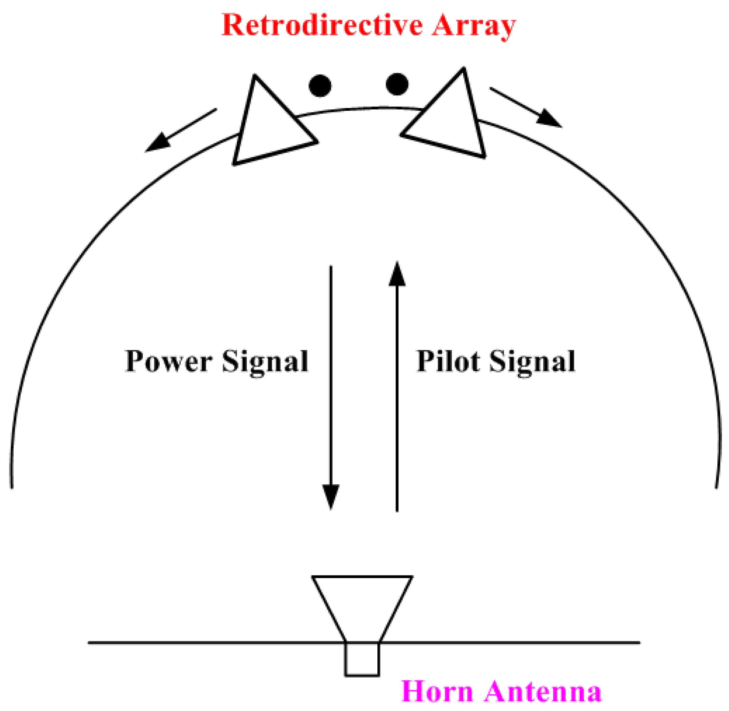
2. Digital Retrodirective Method

Figure 2 represents concept of digital retrodirective method. Pilot signal is sent from rectenna towards retrodirective array. Retrodirective array consists of pilot signal receiving antennas (RX) and power signal transmitting antennas (TX). ϕ r 1 is phase of pilot signal, received by RX1 and ϕ r 2 is phase of pilot signal, received by RX2. Phase detection of pilot signal is performed by DSP circuit. Then, DSP circuit performs beam forming for power signal by phase conjugation of pilot signal and considering frequency of power signal. Phase of the power signal ( ϕ t ) is determined by Equation (1):
ϕ t = f t f r ϕ r ,
where f t is frequency of the transmitted power signal, and f r is frequency of received pilot signal. Power signals with phase ϕ t 1 and ϕ t 2 are radiated by power signal transmitting antennas TX1 and TX2, respectively. To depict configuration for deformation, RX2 and TX2 antennas are deformed from their original position. Each set of pilot signal and power signal transmitting antenna is working independently without synchronization among them.
Figure 3 shows algorithm for digital retrodirective method. For no deformation case and deformation case, phase of pilot signal is determined. Then, power signal for required frequency is generated. Phase of the power signal is determined by converting phase of pilot signal to the power signal frequency, as shown by Equation (1). After that, Conjugation for the power signal phase is performed, and power beam is transmitted.
Details of DSP circuit are shown in Figure 4. DSP circuit has analog front-end, analog-to-digital conversion, and digital signal processing. Software defined radio (SDR) hardware is used for analog front-end and analog-to-digital conversion. Received pilot signal is amplified by low noise amplifier (LNA) and downconverted to baseband in-phase (I) and quadrature-phase (Q) components by mixer. I/Q components are filtered by low pass filter (LPF) and then digitized by analog-to-digital converter (ADC). Digitized I/Q data is downconverted by digital downconverter (DDC) and passed to the host computer over a standard gigabit Ethernet connection.
For power signal transmission, I/Q baseband components with conjugate phases are generated by host PC and fed to digital up converter (DUC). After digital upconversion, digital-to-analog converter (DAC) converts the signal to analog. Then, LPF reduces high frequency components in the signal and mixer upconverts the signal to user-specified RF frequency.
The area within the dotted line indicates processing with field programmable gate array (FPGA), and it is controlled by LabVIEW software. LabVIEW performs phase detection of the pilot signal and generates power signal with phase conjugation.
There is a concern that aliasing can occur when using different frequencies for power signal and pilot signal. It is described in Section 1 that 5.8 GHz and 2.45 GHz frequencies are proposed for power signal and pilot signal, respectively. Aliasing can take place when reconstructing power signal from samples of the pilot signal. In the proposed method, power signal is generated by SDR hardware and phase information of pilot signal is used for getting phase of power signal, as given in Equation (1) and represented by Figure 2, Figure 3 and Figure 4. So, aliasing will not occur for the proposed method with using different frequencies for power signal and pilot signal.

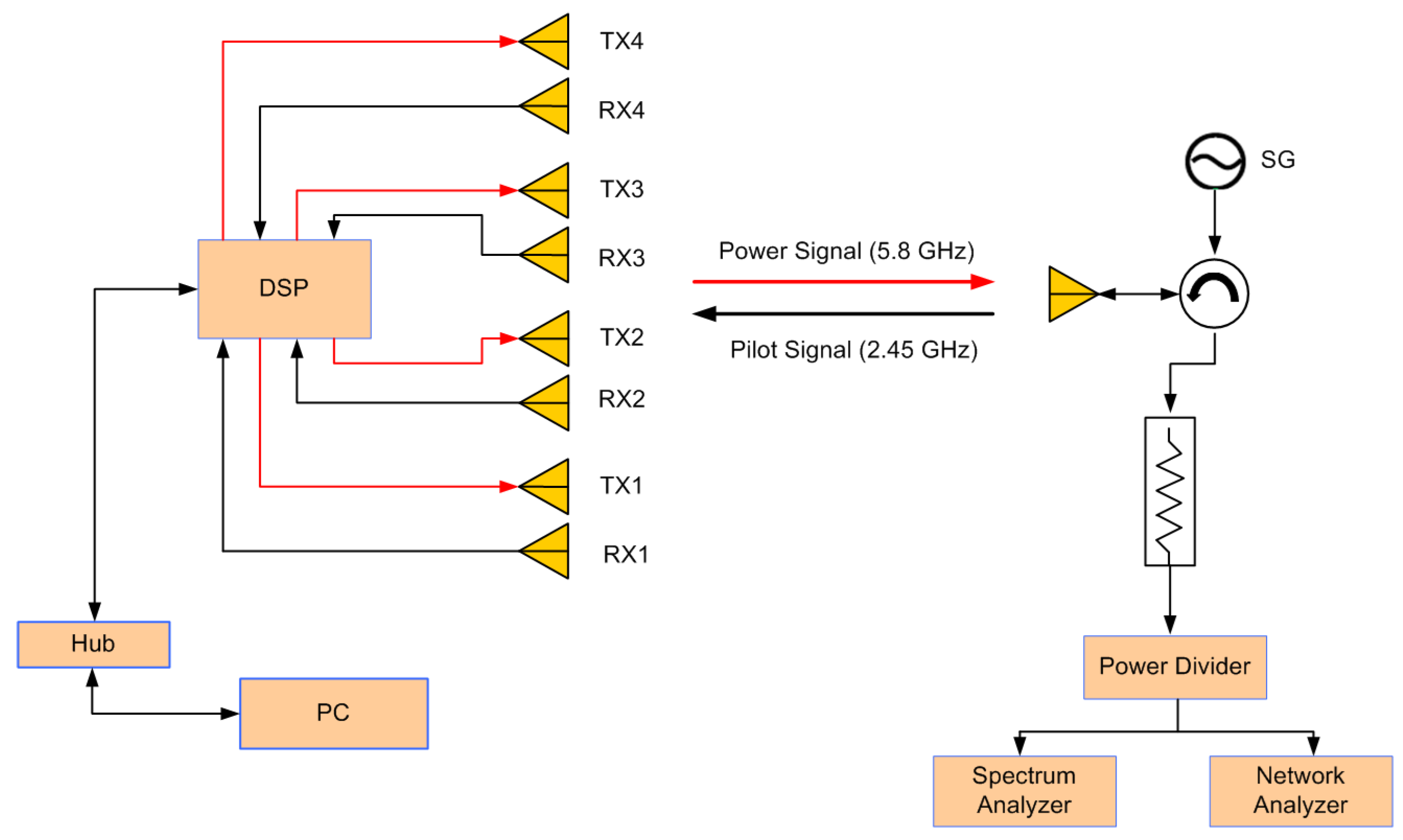
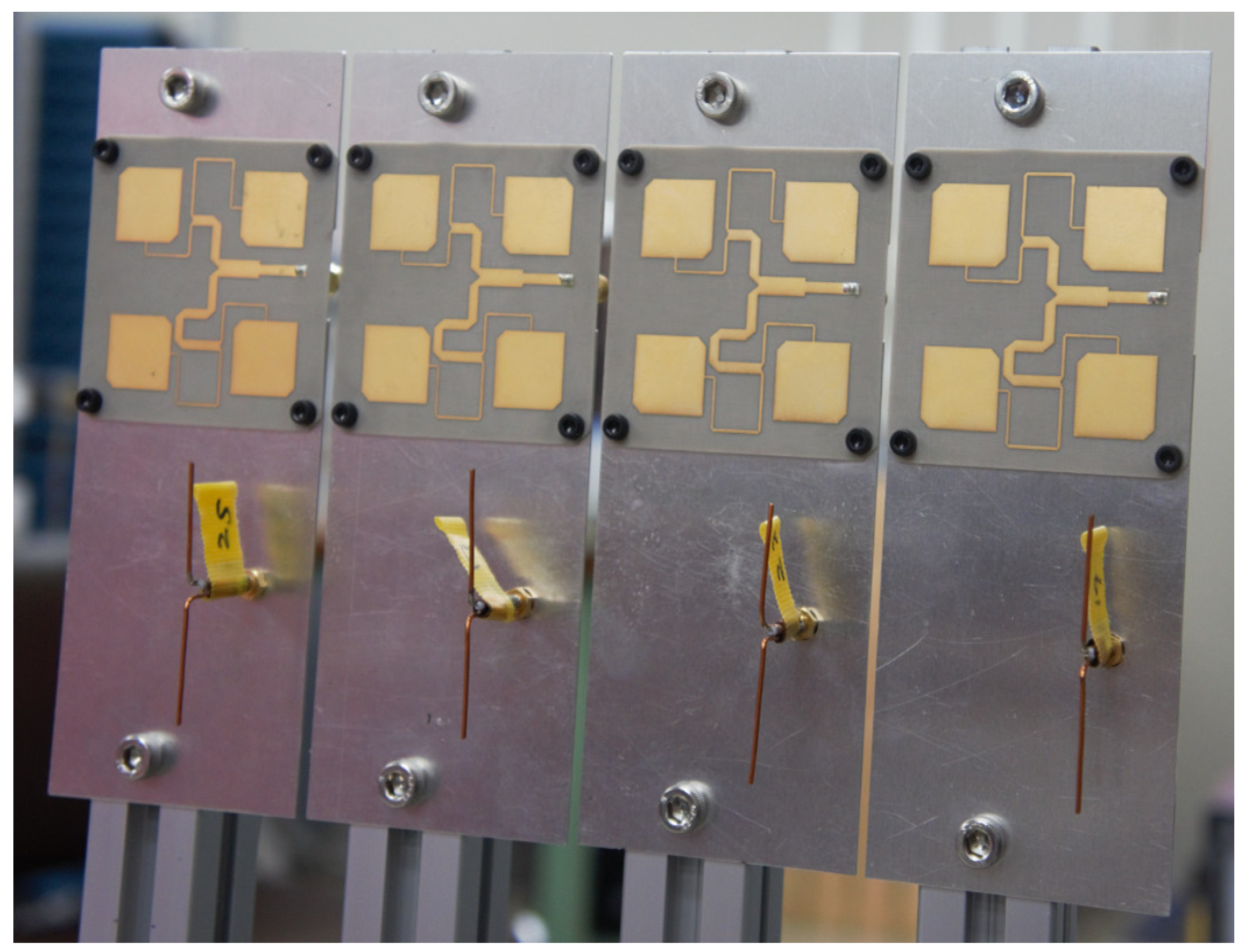
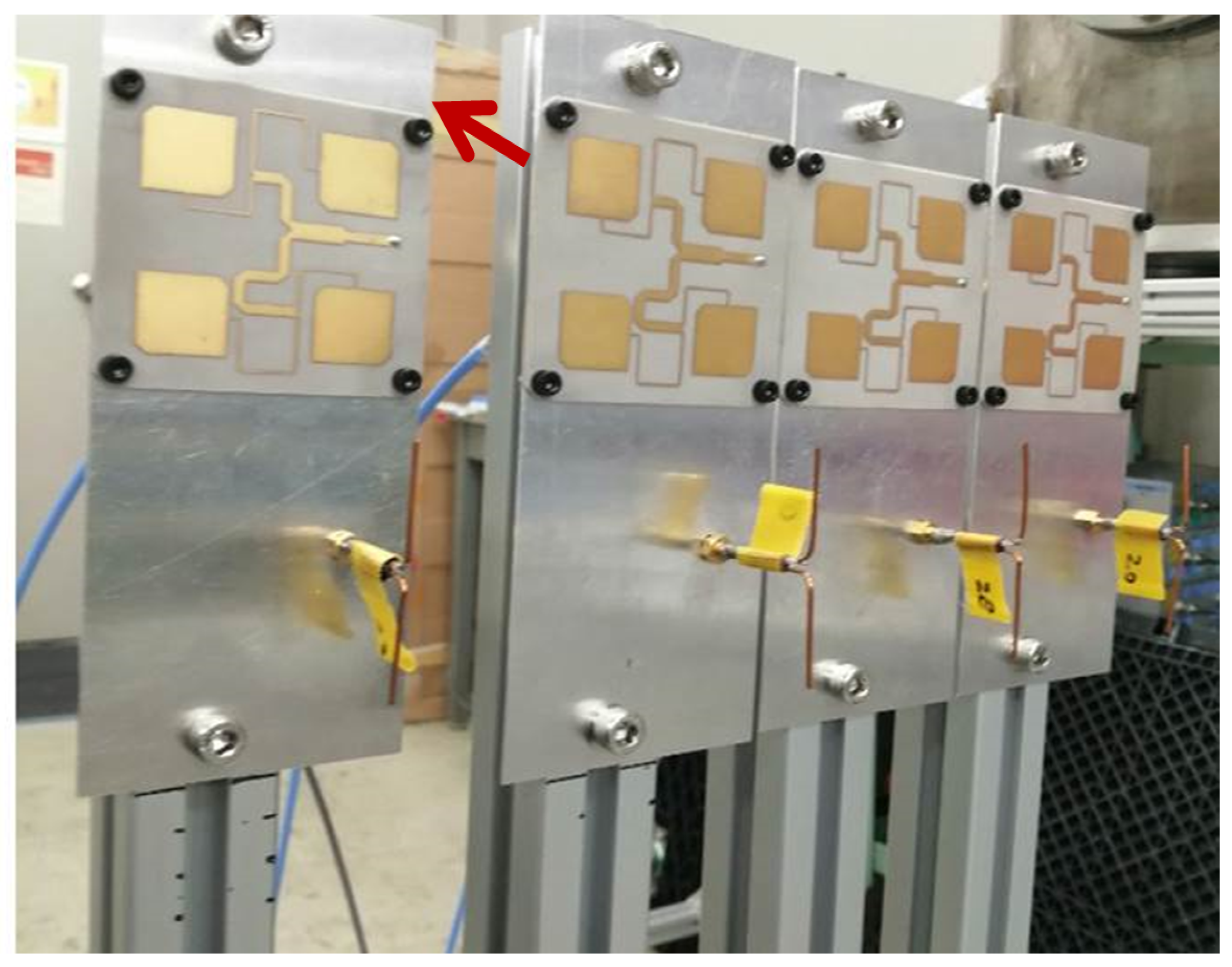
3. Experimental Setup

Bistatic radiation pattern measurement is performed for evaluation of digital retrodirective method, as shown in Figure 5. Retrodirective array is installed on turn table in anechoic chamber, and horn antenna is fixed. The horn antenna sends pilot signal, and it is received by pilot signal receiving antennas. Then, retrodirective array moves on turn table, and power signal transmitting antennas send power signal to horn antenna. Radiation pattern is measured for the power signal, received by horn antenna.
Detailed setup configuration for digital retrodirective experiment is depicted in Figure 6. Considering the case of the Tethered SPS, 2.45 GHz and 5.8 GHz frequencies are used for pilot signal and power signal, respectively. A two and forty-five hundredths gigahertz pilot signal is sent from signal generator (SG) to horn antenna. The horn antenna radiates pilot signal towards retrodirective array. Four sets of pilot signal receiving and power signal transmitting antennas are used for retrodirective array. Antennas are working independently, so this small scale demonstration can determine the usefulness of proposed method for SPS. Half wavelength dipole antennas are used to receive pilot signal. Right-hand circular polarized patch subarray antennas are used to transmit power signal. For SDR hardware, two USRP 2943 are used. Power signal is received by horn antenna, and radiation pattern analysis is performed by network analyzer and spectrum analyzer.
Figure 7 shows retrodirective array setup with patch subarray antennas and dipole antennas. Each patch subarray is working independently with respective dipole antenna. Spacing between each patch subarray is 1.3 λ , and spacing between elements of a subarray is 0.65 λ . For no deformation case, antennas are in original position. Forward and backward deformation cases are represented in Figure 8 and Figure 9 respectively. One patch with respective dipole antenna is deformed in forward and backward direction.

4. Results and Discussion

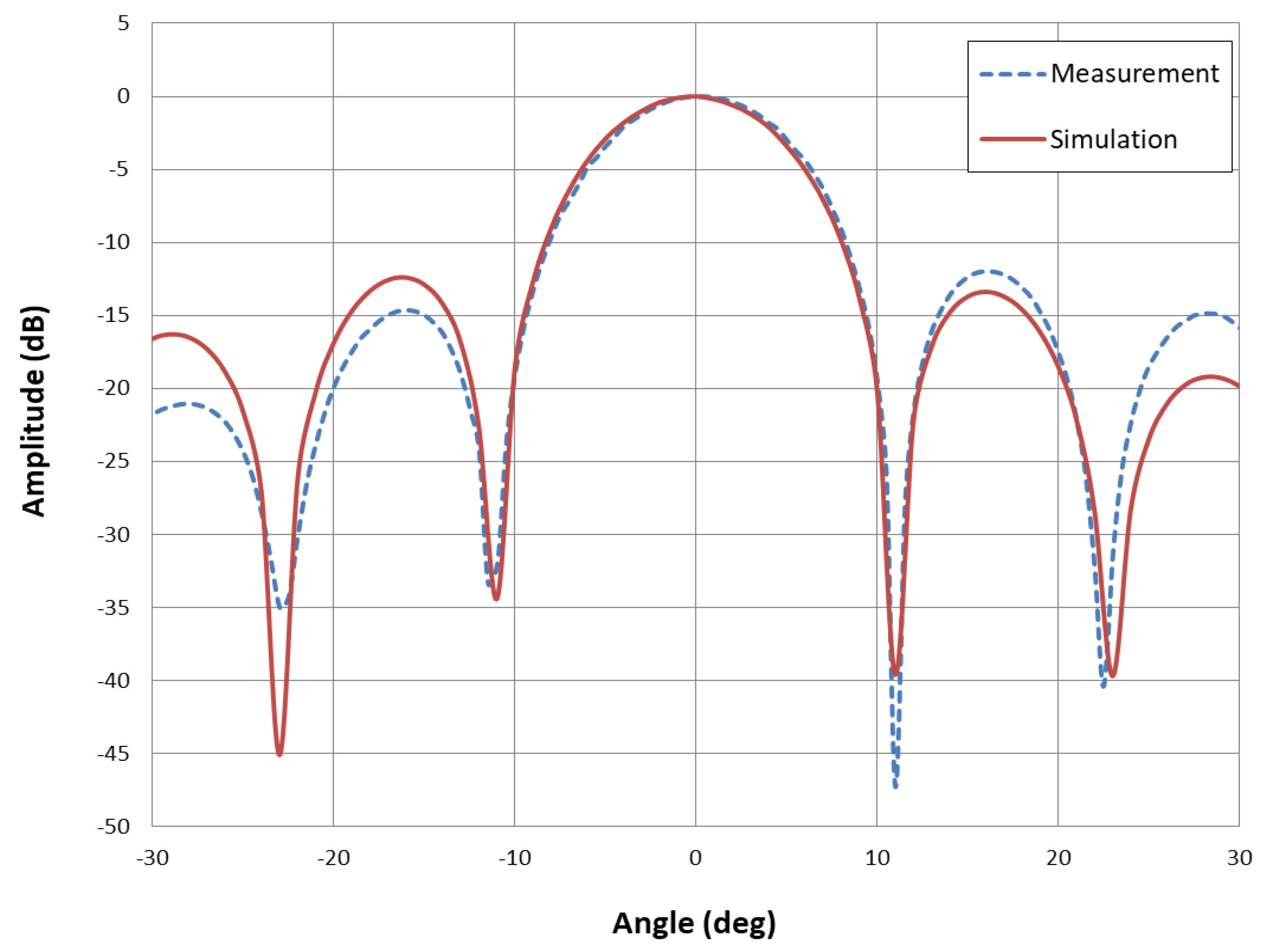
4.1. No Deformation Case

Digital retrodirective method is confirmed for beam forming towards 0 and 5 . Pilot signal is sent towards 0 and 5 positions of retrodirective array. Figure 10 represents radiation pattern of power signal for 0 beam forming. Radiation pattern is measured from −30 to 30 . Three decibels beam-width is 9.8 and side lobe level is −13 dB. The measured pattern, especially the main lobe matches those simulated closely. Simulations are performed by using CST software. Figure 11 shows radiation pattern of power signal for 5 beam forming. Half power beam-width is 9.5 , and side lobe level is −12 dB. Simulated and measured results are in good agreement and represent that digital retrodirective method is performing well.

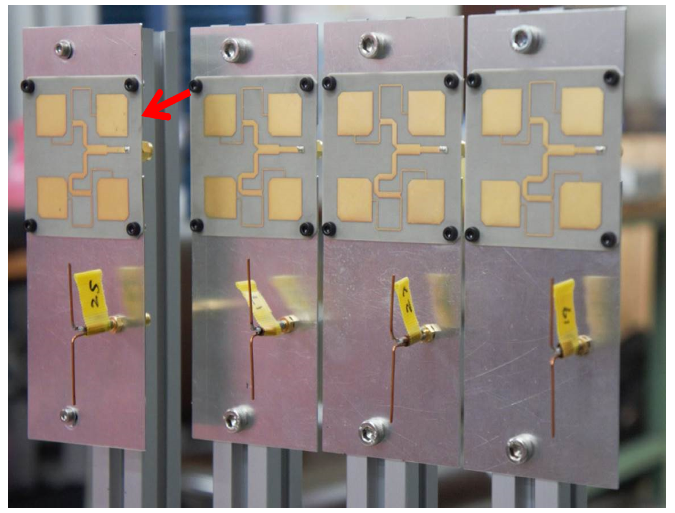
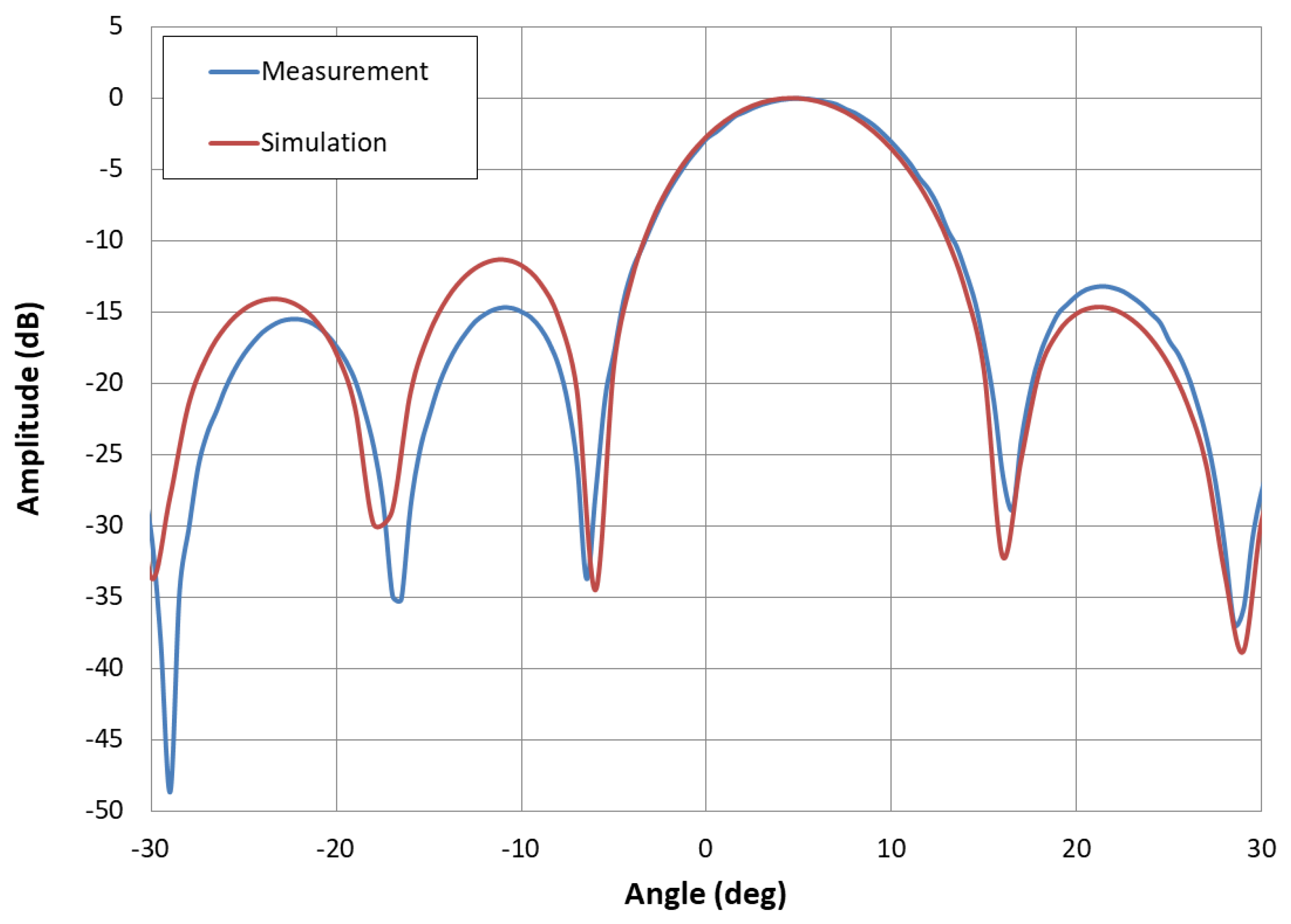
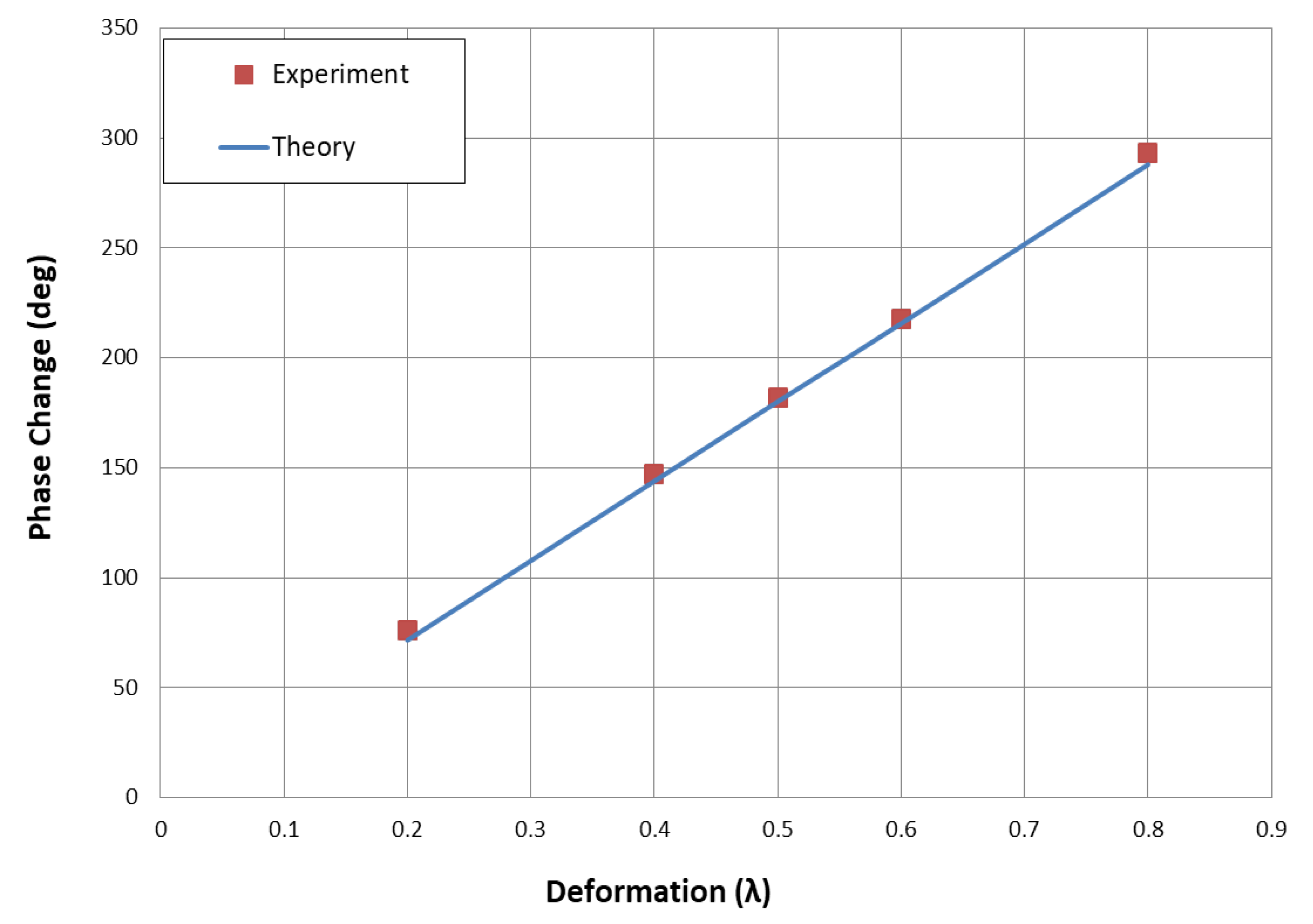
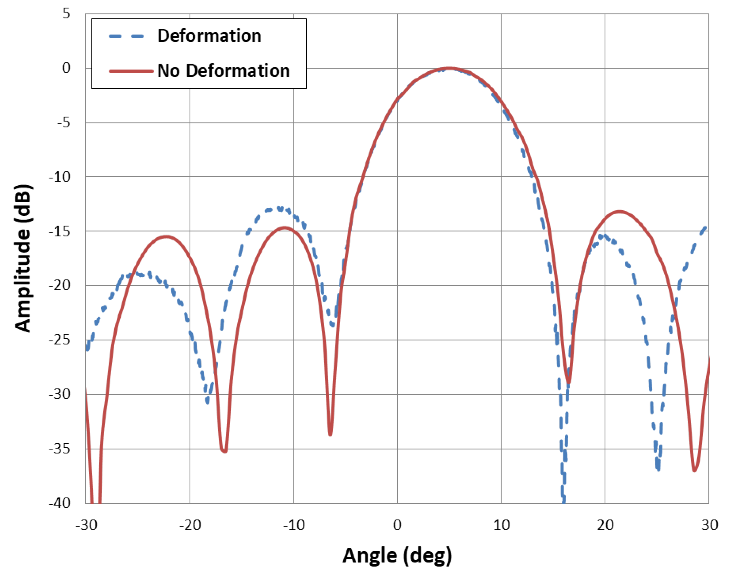
4.2. Deformation Case

For deformation cases, analysis is performed for phase change of pilot signal with deformation. Figure 12 depicts comparison between theoretical data and measured data. Theoretical data is obtained by Equation (2):
Δ ϕ = 2 π Δ x λ ,
where Δ ϕ shows phase change of pilot signal by deformation, and Δ x represents dimension for deformation. Then, 0.2 λ , 0.4 λ , 0.5 λ , 0.6 λ , and 0.8 λ deformation cases are compared. Theoretical and measurement data is correlated in Figure 12.
DSP circuit, as shown in Figure 4, has ADC component, and it generates main quantization error. Analysis is performed to measures phase change error and power signal beam pointing error. Phase measurement error for antenna deformation cases is represented in Table 1, and RMS error for phase change is 3.495 . Power signal beam pointing RMS error is calculated by Equation (3) [12,24]:
Δ θ = 2 λ π d cos θ , M 1.5 δ ϕ ,
where Δ θ is beam pointing RMS error, d is spacing between antenna subarray, M is number of elements in the array, and δ ϕ is phase RMS error. For M = 4, θ = 0 , d = 1.3 λ , δ ϕ = 3.495 , Δ θ was determined as 0.21 RMS. Beam width of power signal beam is 9.8 and 10% of beam-width is 0.98 . So, beam pointing error by digital retrodirective method satisfies accuracy requirement for SPS. Each subarray is working independently and will be working in the same manner for SPS. Probability density distribution for phase change error is also represented in Figure 13.
Further, 0.5 λ deformation case produces maximum phase change of pilot signal. So, radiation patterns with 0.5 λ case are analyzed. Figure 14 represents radiation pattern for 0.5 λ forward deformation case. With retrodirective plot is measured data for digital retrodirective method with deformation. Simulation plot is simulated data for the deformation with digital retrodirective method. Without retrodirective pattern is when digital retrodirective method is not used for deformation. Simulated and measured data with retrodirective method are in good agreement. Without retrodirective plot shows that main lobe is directed to −8 , and side lobe level is −3 dB. So, the effect of deformation is resolved by using the digital retrodirective method.
Figure 15 represents comparison of digital retrodirective method and REV method for antenna deformation. We compare the 0.5 λ deformation case, and the radiation pattern shows that both methods are in good agreement with the simulation. REV method takes long time for the process, so digital retrodirective method has advantage over REV method to correct radiation pattern for antenna deformation.
Figure 16 represents radiation pattern for 0.5 λ backward deformation case. With retrodirective plot correlates with the simulation, having beam-width of 9.7 and side lobe level of −12 dB. Without retrodirective pattern has −5.1 main lobe direction of and −3.4 dB side lobe level. Figure 17 depicts comparison of digital retrodirective method for no deformation and deformation case. Pilot signal is sent from 5 , and measured patterns are compared. Both plots are in good agreement, and this shows that effect of antenna deformation is resolved successfully by digital retrodirective method.
Experimental results of digital retrodirective method show that appropriate radiation patterns are obtained for no deformation and deformation cases.

5. Conclusions

This paper presented digital retrodirective method to perform MPT for SPS. Four dipole antennas received pilot signal from the rectenna, and four patch subarrays transmitted power signal towards rectenna. DSP circuit was used for pilot signal phase detection and power signal beam forming with phase conjugation. Digital retrodirective method’s algorithm performed well for correction of antenna deformation effect. Each subarray worked independently with respective dipole antenna, and synchronization was not required for beam forming. Phase change measurement error was 3.495 RMS, and beam pointing error was 0.21 RMS. Comparison was also done for antenna deformation and no deformation cases. REV method was also in correlation with digital retrodirective method. This study suggests that the proposed method is suitable to resolve issues of beam forming for SPS.

Author Contributions

Conceptualization, M.R. and K.T.; methodology, M.R. and K.T.; software, M.R.; validation, M.R. and K.T.; formal analysis, M.R.; investigation, M.R.; resources, K.T.; data curation, M.R.; writing—original draft preparation, M.R.; writing—review and editing, M.R. and K.T.; visualization, M.R.; supervision, K.T.; project administration, M.R. and K.T.; funding acquisition, K.T. All authors have read and agreed to the published version of the manuscript.

Funding

This research was supported in part by SOKENDAI (The Graduate University for Advanced Studies).

Conflicts of Interest

The authors declare no conflict of interest.

References

  1. Glaser, P.E. Power from the sun: Its future. Science 1968, 162, 857–861. [Google Scholar] [CrossRef] [PubMed]
  2. Brown, W.C.; Moreno, T. Microwave power generation. IEEE Spectr. 1964, 1, 77–81. [Google Scholar] [CrossRef]
  3. Brown, W.C. The history of power transmission by radio waves. IEEE Trans. Microw. Theory Technol. 1984, 32, 1230–1242. [Google Scholar] [CrossRef] [Green Version]
  4. Shinohara, N. Beam control technologies with a high-efficiency phased array for microwave power transmission in Japan. Proc. IEEE 2013, 101, 1448–1463. [Google Scholar] [CrossRef] [Green Version]
  5. Sasaki, S.; Tanaka, K.; Higuchi, K.; Okuizumi, N.; Kawasaki, S.; Shinohara, N.; Senda, K.; Ishimura, K. A New Concept of Solar Power Satellite: Tethered-SPS. Acta Astronaut. 2006, 60, 153–165. [Google Scholar] [CrossRef]
  6. Sasaki, S.; Tanaka, K. Demonstration Experiment for Tethered-Solar Power Satellite. Trans. Jpn. Soc. Aeronaut. Space Sci. Space Technol. Jpn. 2009, 7, Tr_1_1–Tr_1_4. [Google Scholar] [CrossRef] [Green Version]
  7. Sasaki, S.; Tanaka, K. Wireless power transmission technologies for solar power satellite. In Proceedings of the 2011 IEEE MTT-S International Microwave Workshop Series on Innovative Wireless Power Transmission: Technologies, Systems, and Applications, Kyoto, Japan, 12–13 May 2011. [Google Scholar]
  8. Sasaki, S.; Tanaka, K.; Ken-ichiro, M. Microwave power transmission technologies for solar power satellites. Proc. IEEE 2013, 101, 1438–1447. [Google Scholar] [CrossRef]
  9. Strassner, B.; Chang, K. Microwave Power Transmission: Historical Milestones and System Components. Proc. IEEE 2013, 101, 1379–1396. [Google Scholar] [CrossRef]
  10. Homma, Y.; Sasaki, T.; Namura, K.; Sameshima, F.; Ishikawa, T.; Sumino, H.; Shinohara, N. New phased array and rectenna array systems for microwave power transmission research. In Proceedings of the 2011 IEEE MTT-S International Microwave Workshop Series on Innovative Wireless Power Transmission: Technologies, Systems, and Applications, Uji, Kyoto, Japan, 12–13 May 2011; pp. 59–62. [Google Scholar]
  11. Hashimoto, K.; Matsumoto, H. Retrodirective system for solar power satellites. In Proceedings of the 57th International Astronautical Congress, Valenica, Spain, 2–6 October 2006. [Google Scholar]
  12. Miyakawa, T.; Yajima, M.; Fukumuro, Y.; Sasaki, S.; Sasaki, T.; Homma, Y.; Namura, K. Development status of the beam steering control subsystem for the microwave power transmission ground experiment. In Proceedings of the IEEE MTT-S International Microwave Workshop Series on Innovative Wireless Power Transmission: Technologies, Systems, and Applications, Kyoto, Japan, 12–13 May 2011. [Google Scholar]
  13. Iwashita, M.; Kaya, N. The demonstration of microwave-beam control in international symposium on solar energy from space. In Proceedings of the International Symposium on Space Technology and Science, Ginowan, Japan, 5–12 June 2011. [Google Scholar]
  14. Yamagami, T.; Nakamura, T.; Sekiya, N.; Arai, K.; Tanaka, K. Modeling and Simulation of Carbon Nanotube based Electro-active Polymers for Shape-keeping of the Large-scale Space structure. In Proceedings of the International Symposium on Space Technology and Science, Fukui, Japan, 15–21 June 2019. [Google Scholar]
  15. Takahashi, T.; Sasaki, T.; Homma, Y.; Mihara, S.; Sasaki, K.; Nakamura, S.; Makino, K.; Joudoi, D.; Ohashi, K. Phased array system for high efficiency and high accuracy microwave power transmission. In Proceedings of the 2016 IEEE International Symposium on Phased Array Systems and Technology, Waltham, MA, USA, 18–21 October 2016. [Google Scholar]
  16. Hashimoto, K.; Matsumoto, H. Microwave beam control system for solar power satellite. In Proceedings of the Asia-Pacific Radio Science Conference, Qingdao, China, 24–27 August 2004. [Google Scholar]
  17. Matsumoto, H. Research on solar power satellites and microwave power transmission in Japan. IEEE Microw. Mag. 2002, 3, 36–45. [Google Scholar] [CrossRef]
  18. Takahashi, T.; Mizuno, T.; Sawa, M.; Sasaki, T.; Takahashi, T.; Shinohara, N. Development of phased array for high accurate microwave power transmission. In Proceedings of the Microwave Workshop Series on Innovative Wireless Power Transmission: Technologies, Systems, and Applications (IMWS), Kyoto, Japan, 12–13 May 2011. [Google Scholar]
  19. Raza, M.; Tanaka, K.; Katano, S. Experiment on Direction Finding Using Array Antenna for Solar Power Satellite. In Proceedings of the 2018 Asia-Pacific Microwave Conference (APMC), Kyoto, Japan, 6–9 November 2018. [Google Scholar]
  20. Mihara, S.; Sato, M.; Nakamura, S.; Sasaki, K.; Homma, Y.; Sasaki, T.; Ozawa, Y.; Tanaka, N.; Fujiwara, T. The result of ground experiment of microwave wireless power transmission. In Proceedings of the 66th Int. Astronautical Congress, Jerusalem, Israel, 12–16 October 2015.
  21. Raza, M.; Tanaka, K. Preliminary Study of antenna deformation for Wireless Power Transmission of Solar Power Satellite. In Proceedings of the 2019 International Symposium on Antennas and Propagation (ISAP), Xi’an, China, 27–30 October 2019; pp. 1–3. [Google Scholar]
  22. Varasteh, M.; Piovano, E.; Clerckx, B. A Learning Approach to Wireless Information and Power Transfer Signal and System Design. In Proceedings of the ICASSP 2019—2019 IEEE International Conference on Acoustics, Speech and Signal Processing (ICASSP), Brighton, UK, 12–17 May 2019; pp. 4534–4538. [Google Scholar] [CrossRef] [Green Version]
  23. Perera1, T.D.P.; Jayakody, D.N.K.; De, S.; Ivanov, M.A. A Survey on Simultaneous Wireless Information and Power Transfer. In Proceedings of the International Conference on Information Technologies in Business and Industry, Tomsk, Russian, 21–26 September 2016. [Google Scholar]
  24. Tanaka, K.; Maki, K.; Sasaki, S. Development of Phased-Array Antenna System for Wireless Power Transmission Experiment. In Proceedings of the 64th International Astronautical Congress, Beijing, China, 23–27 September 2013. [Google Scholar]
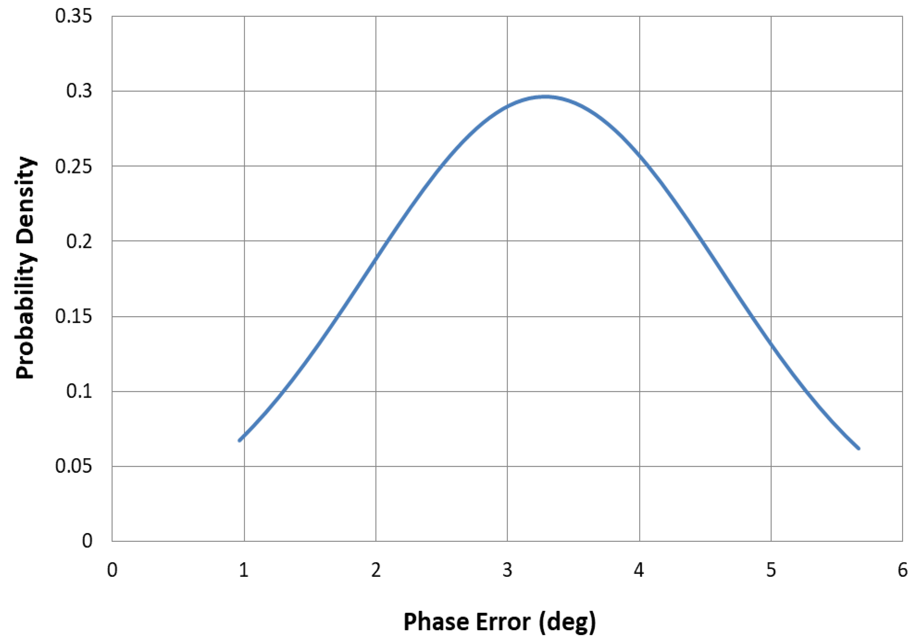
Figure 1. Tethered Solar Power Satellite (SPS).
Electronics 10 00498 g001
Figure 2. Digital Retrodirective method concept.
Electronics 10 00498 g002
Figure 3. Digital Retrodirective algorithm.
Electronics 10 00498 g003
Figure 4. Digital Signal Processing (DSP) circuit.
Electronics 10 00498 g004
Figure 5. Bistatic radiation pattern measurement.
Electronics 10 00498 g005
Figure 6. Digital Retrodirective method experimental setup.
Electronics 10 00498 g006
Figure 7. Patch subarrays with dipole antennas.
Electronics 10 00498 g007
Figure 8. Forward antenna deformation configuration.
Electronics 10 00498 g008
Figure 9. Backward antenna deformation configuration.
Electronics 10 00498 g009
Figure 10. No deformation with Digital Retrodirective method for pilot signal from 0 .
Electronics 10 00498 g010
Figure 11. No deformation with Digital Retrodirective method for pilot signal from 5 .
Electronics 10 00498 g011
Figure 12. Deformation analysis for phase.
Electronics 10 00498 g012
Figure 13. Probability density function of phase error.
Electronics 10 00498 g013
Figure 14. Forward deformation with digital Retrodirective method.
Electronics 10 00498 g014
Figure 15. Comparison of Digital Retrodirective method with REV method.
Electronics 10 00498 g015
Figure 16. Backward deformation with Digital Retrodirective method.
Electronics 10 00498 g016
Figure 17. Comparison of no deformation and deformation case.
Electronics 10 00498 g017
Table 1. Root-mean square (RMS) phase error measurement.
Deformation ( λ )Phase Error (Deg)
0.21.8
0.44.31
0.55
0.63
0.82.3
3.495 (RMS)
Publisher’s Note: MDPI stays neutral with regard to jurisdictional claims in published maps and institutional affiliations.

