
The Vulnerability of the Production Line Using Industrial IoT Systems under DDoS Attack

 ,
,  , , , and
Abstract
:1. Introduction
1.1. Related Works
1.2. Contributions
1.3. Recommendations for Securing IIoT and IoT
- data classification
- physical security
- secure installation of the device
- secure operating systems
- application security
- credential management
- encryption
- network connections
- software updates
2. Materials and Methods
2.1. IoT Thermostat
IoT Fibaro Security System
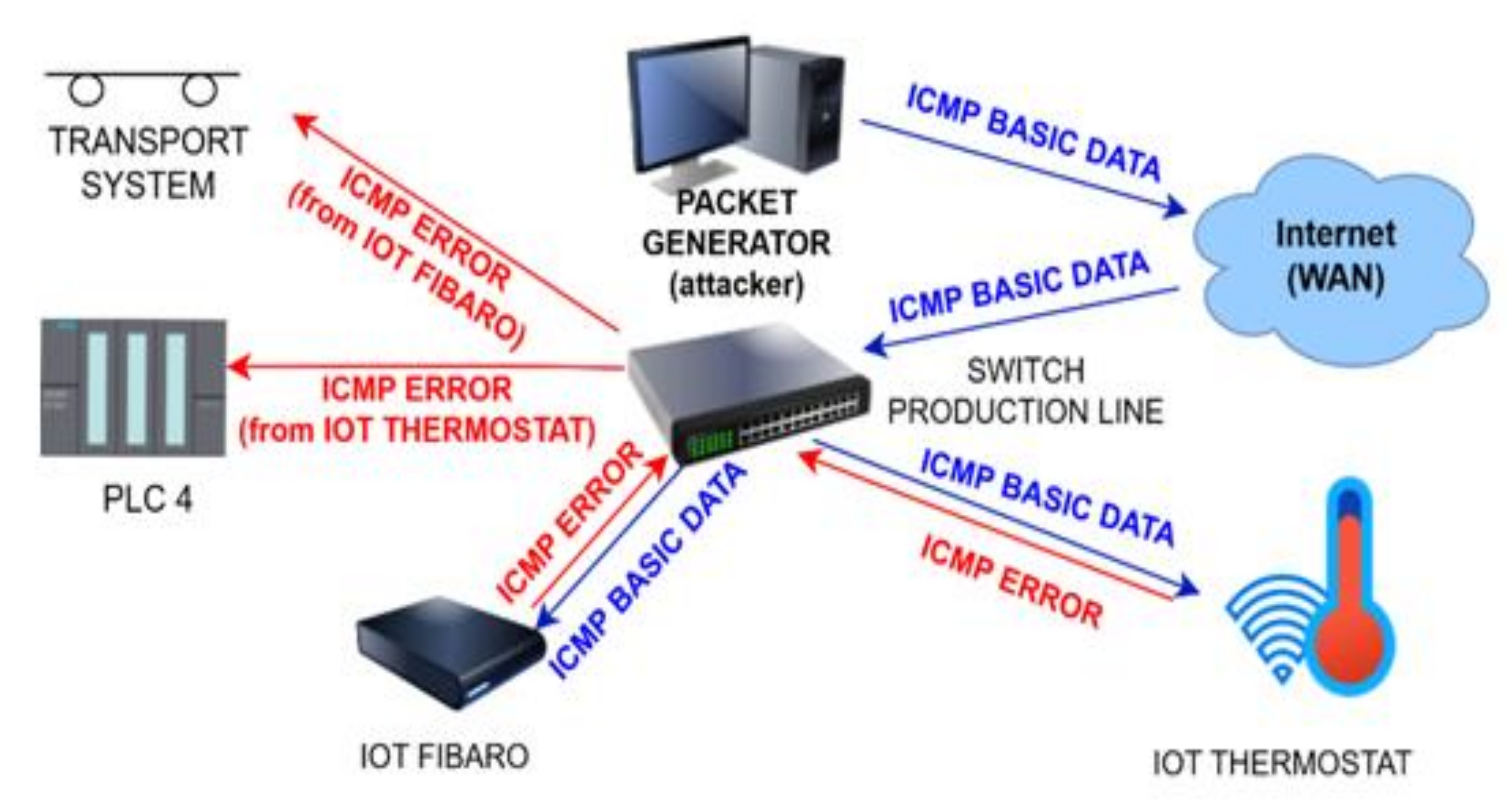
2.2. DDoS Attack
2.2.1. A Reflective DDoS Attack
2.2.2. Types of DDoS Attacks
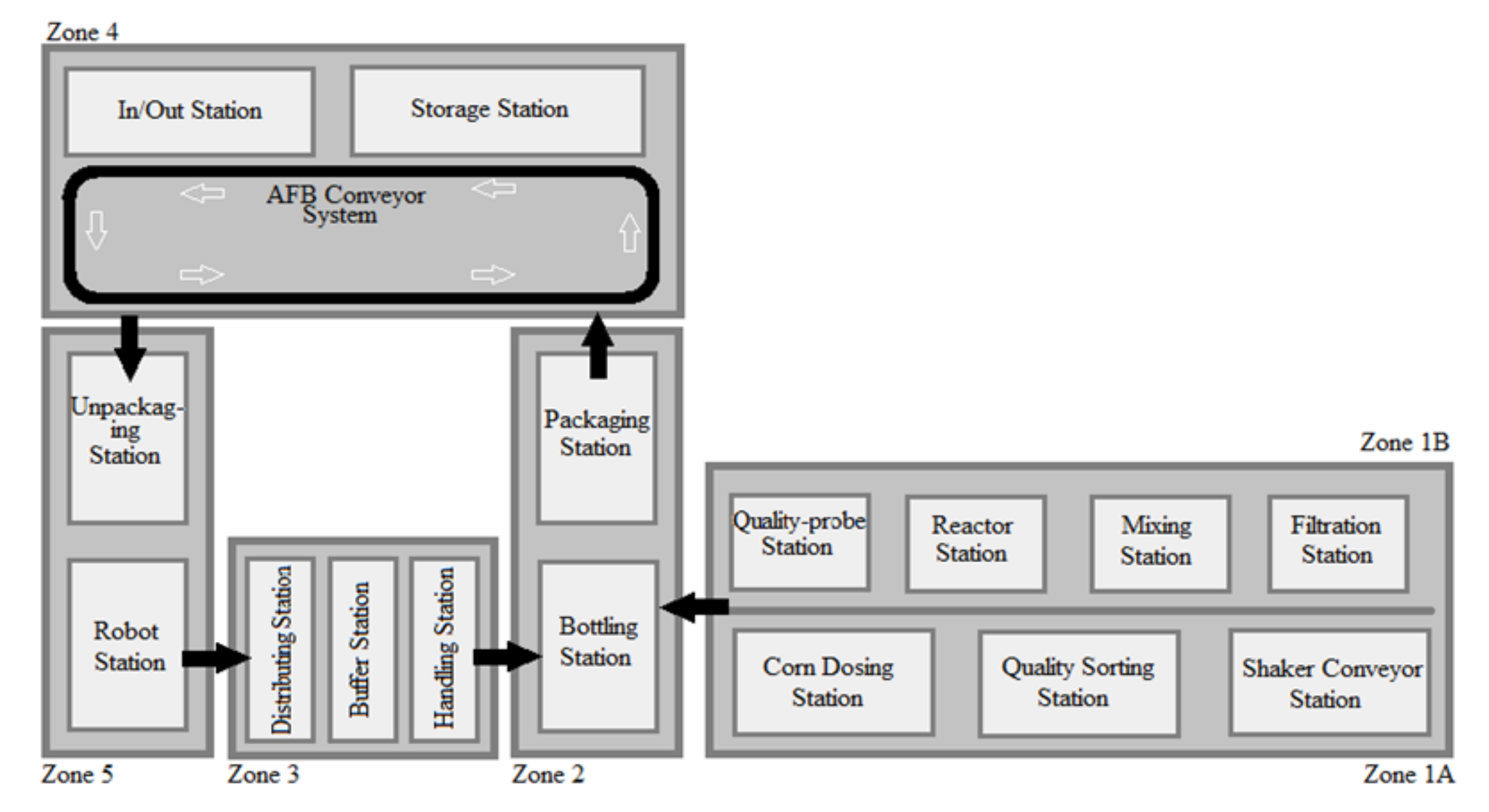
2.3. A Production Line
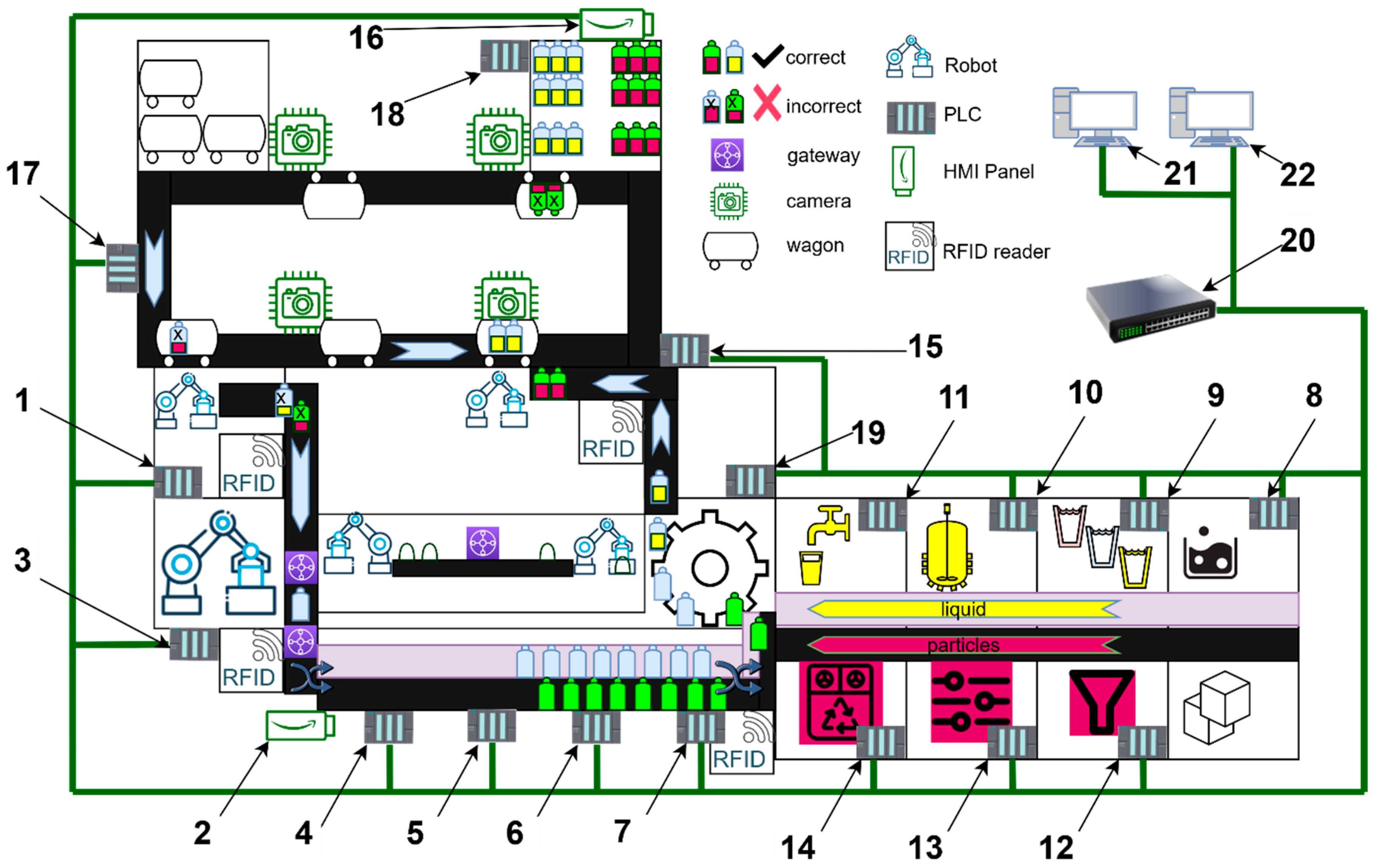
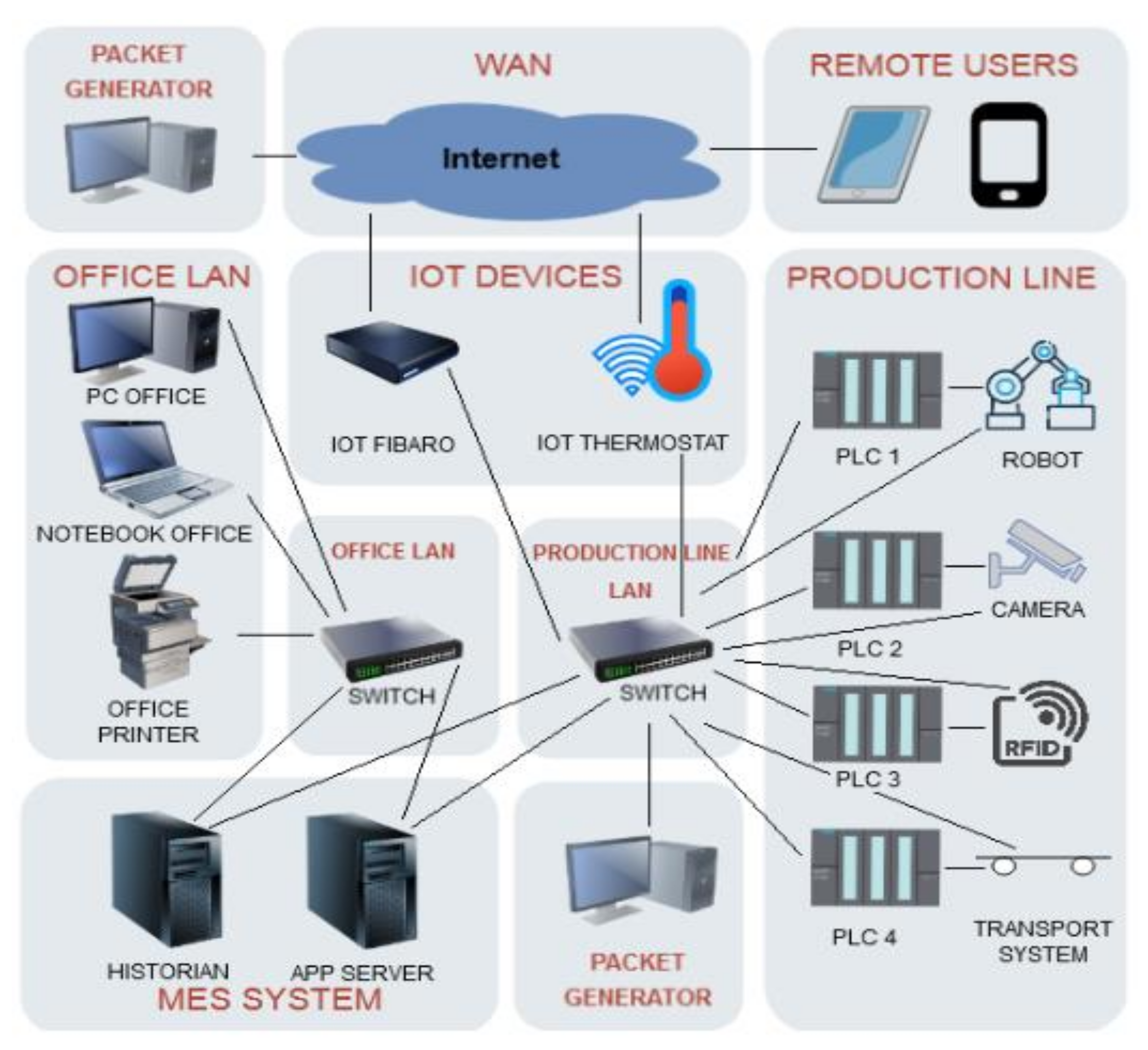
2.3.1. Ethernet Connections
2.3.2. Wonderware Manufacturing Execution System (MES) System
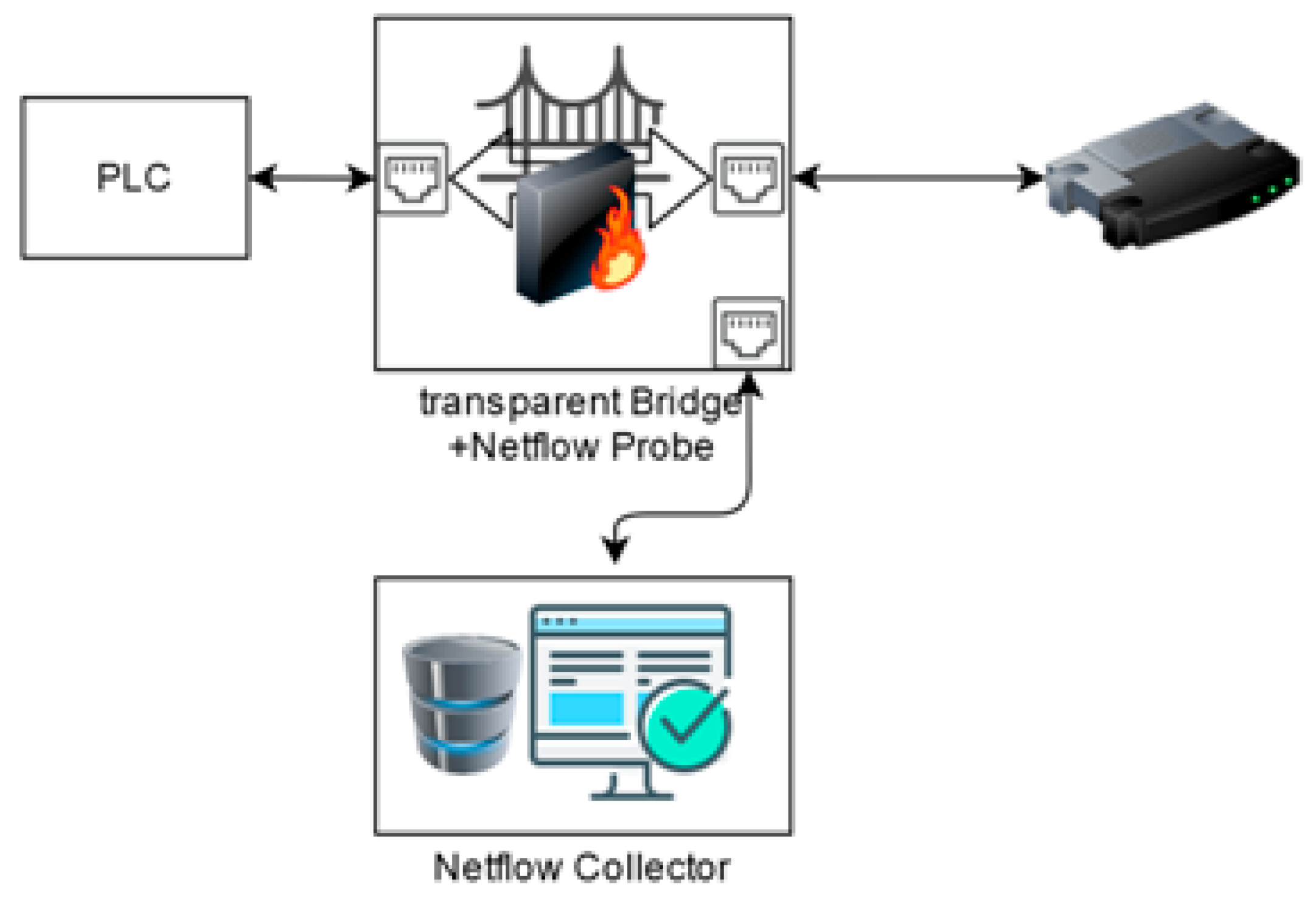
2.4. Real Network Environment for Performing DDoS Attacks
3. Results
3.1. Scenarios
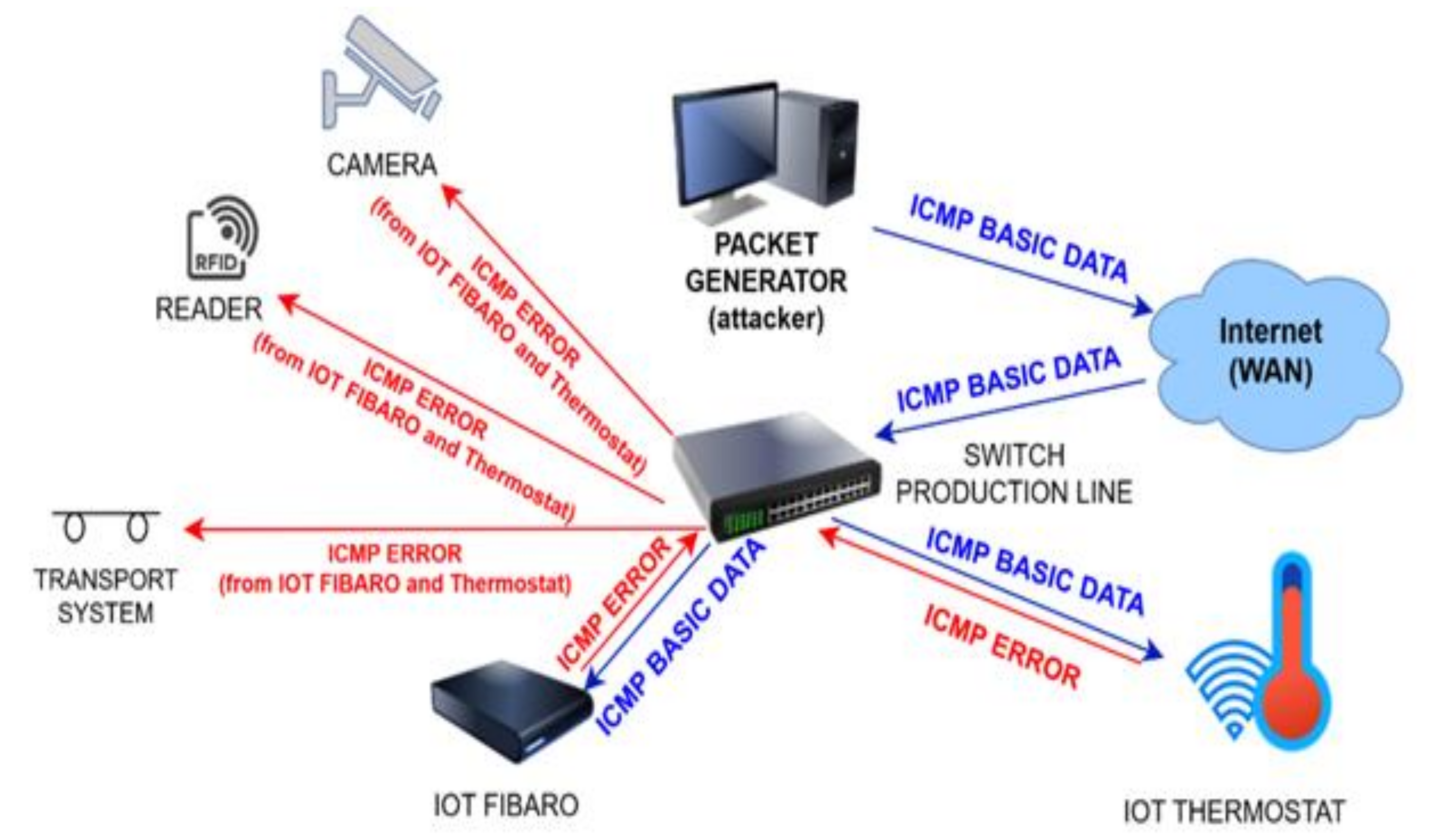
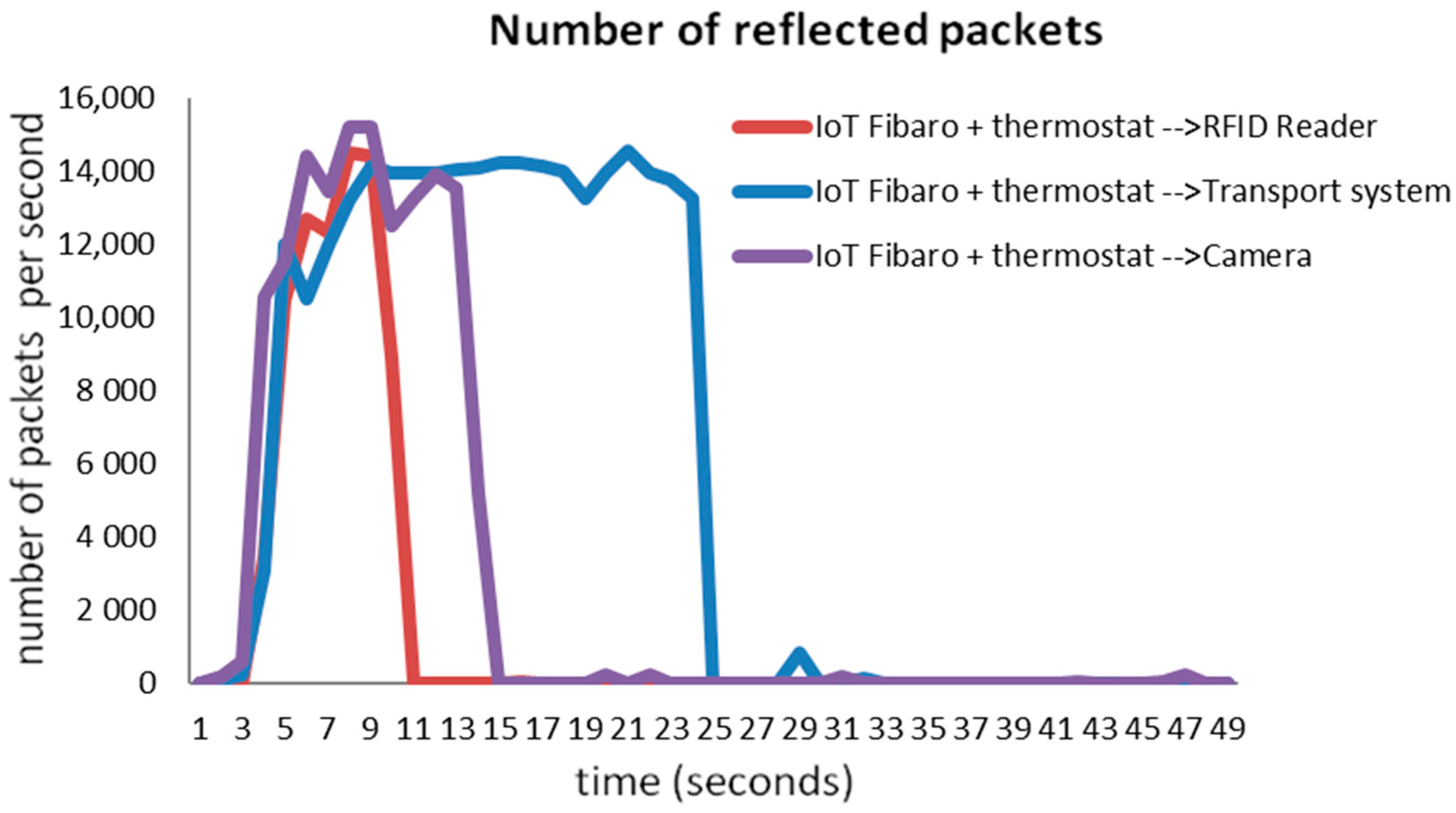
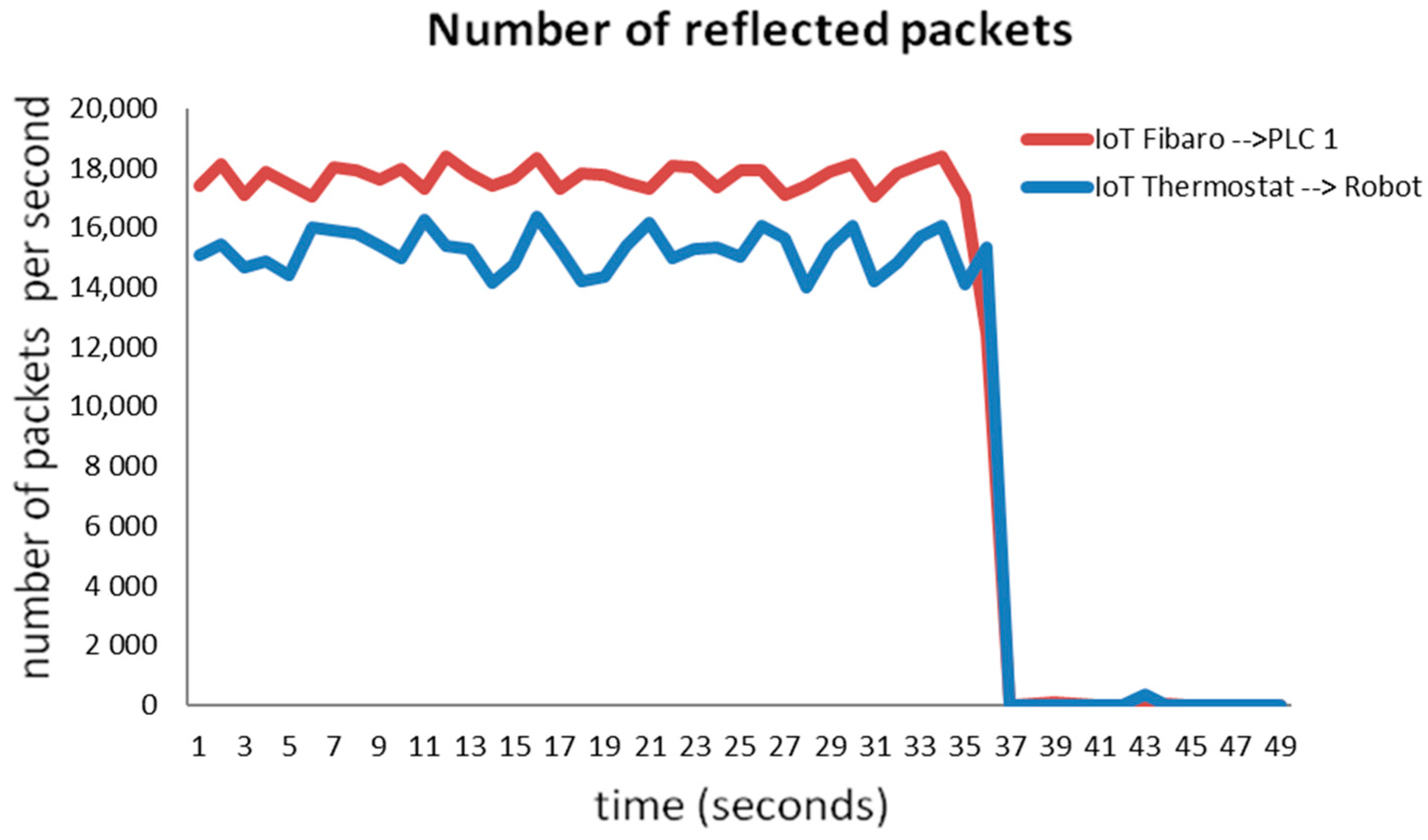
3.1.1. Scenario 1
3.1.2. Scenario 2
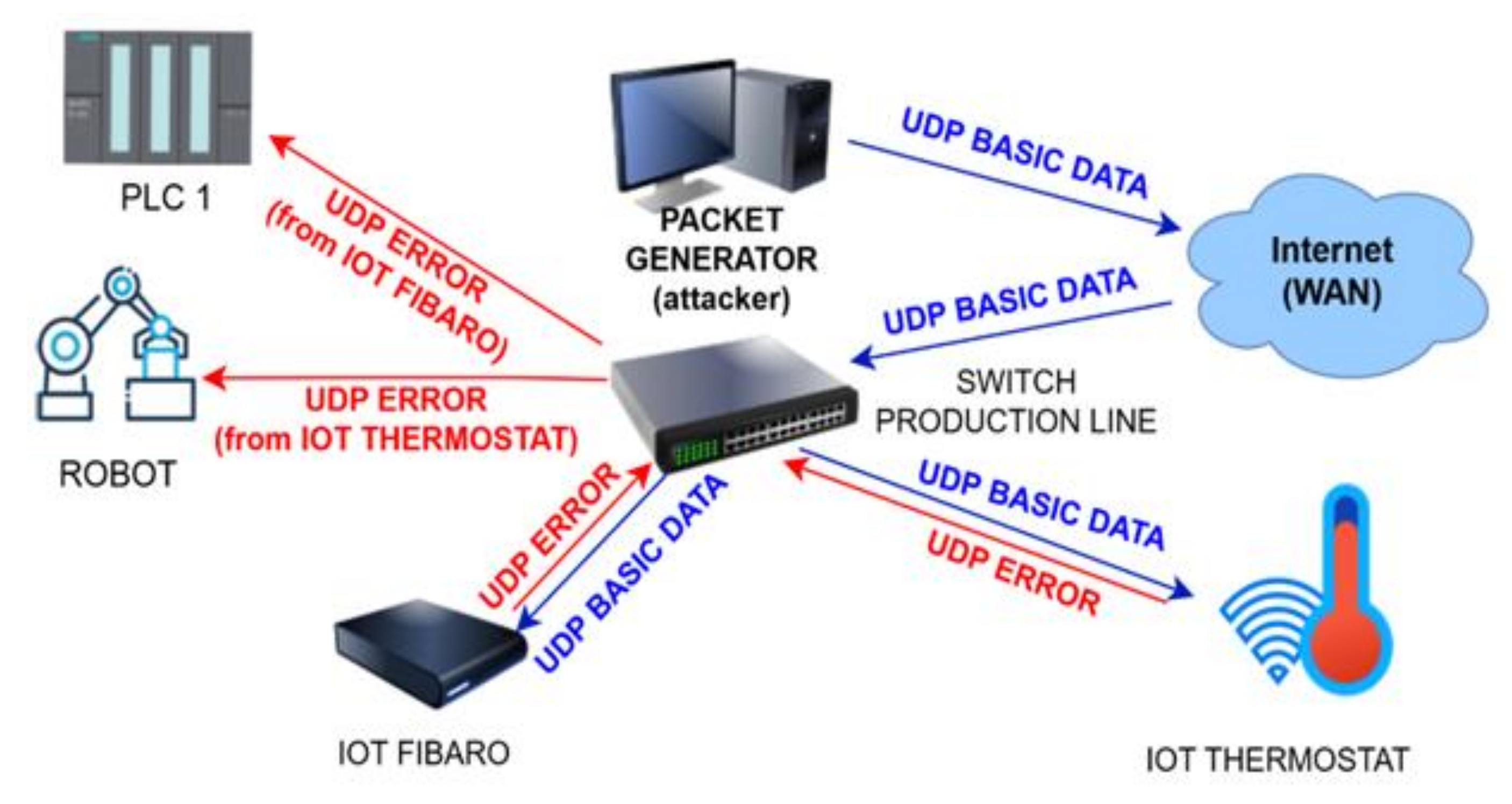
3.1.3. Scenario 3
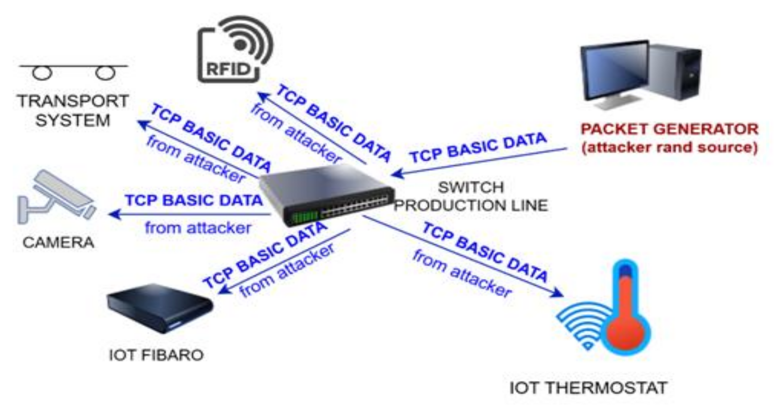
3.1.4. Scenario 4
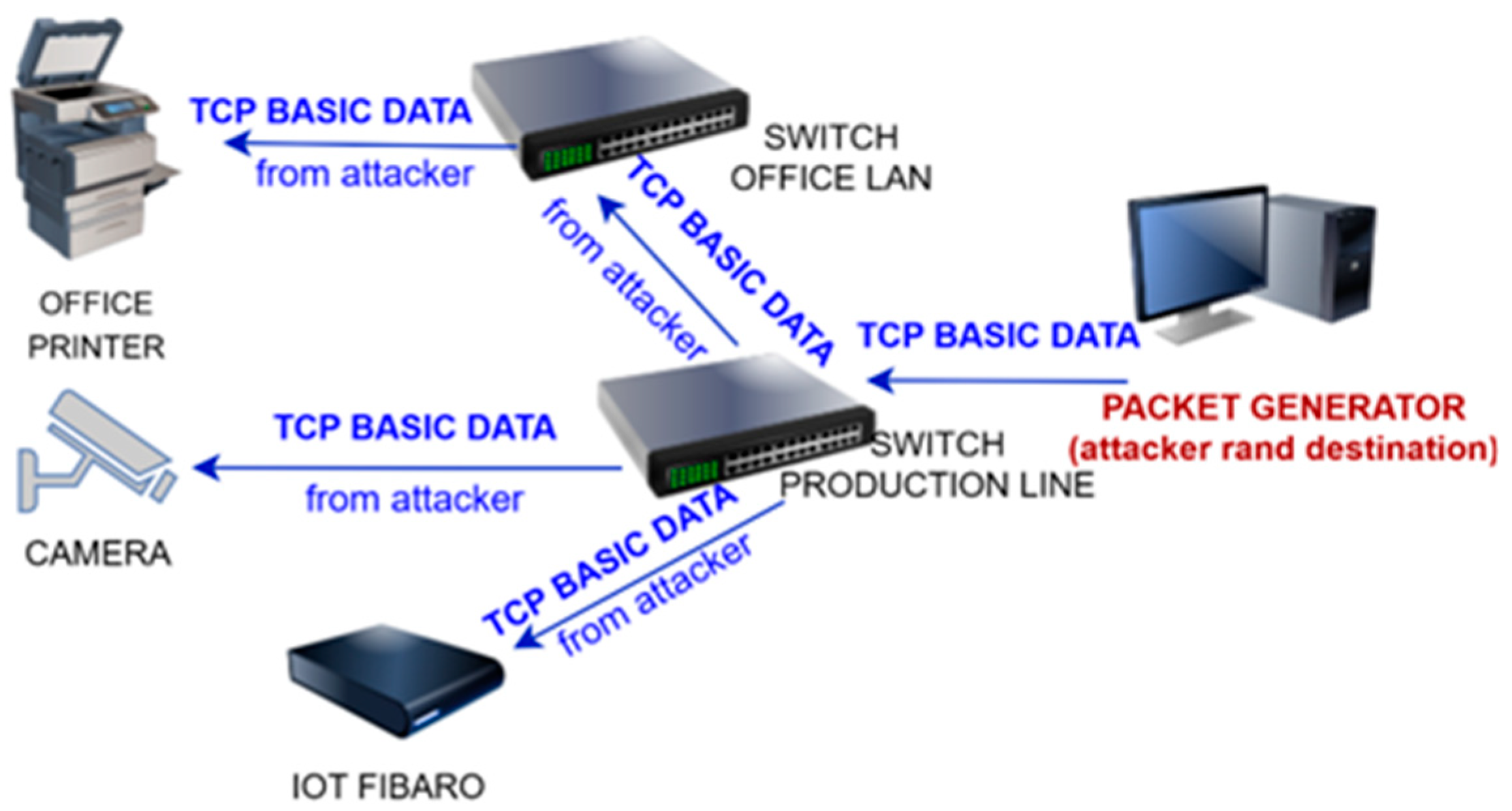
3.1.5. Scenario 5
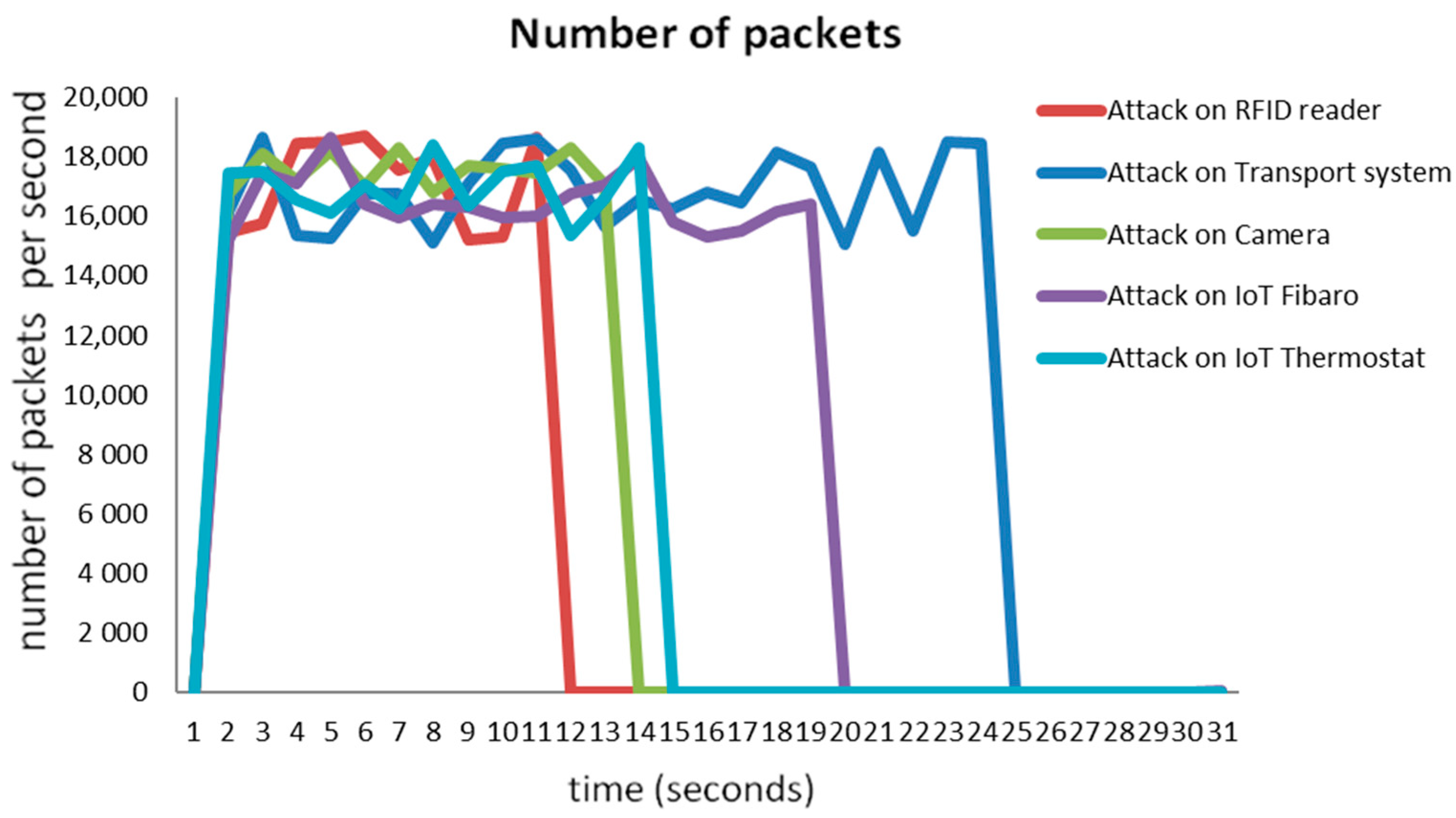
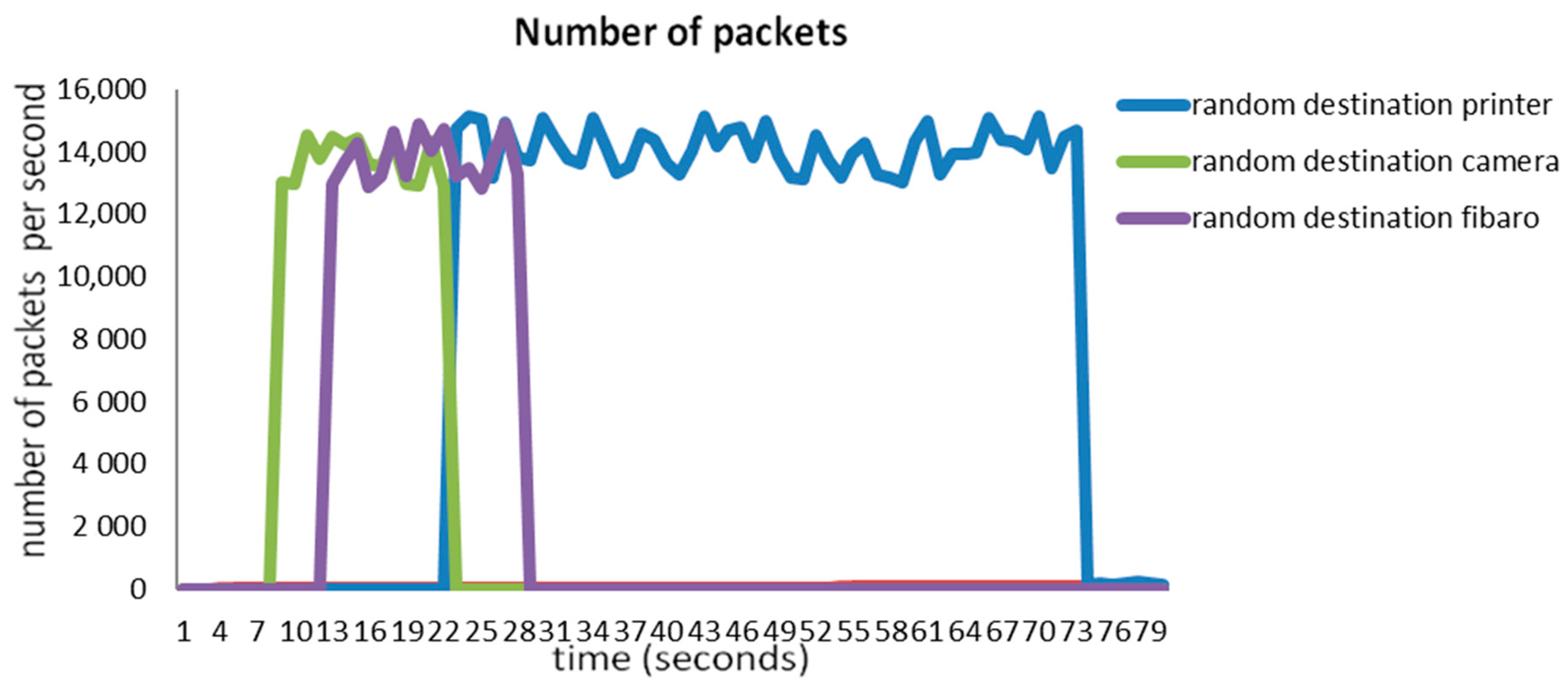
3.1.6. The Overview of Attack Scenarios
3.2. Impacts of DDoS and DRDoS Attacks on the Production Process
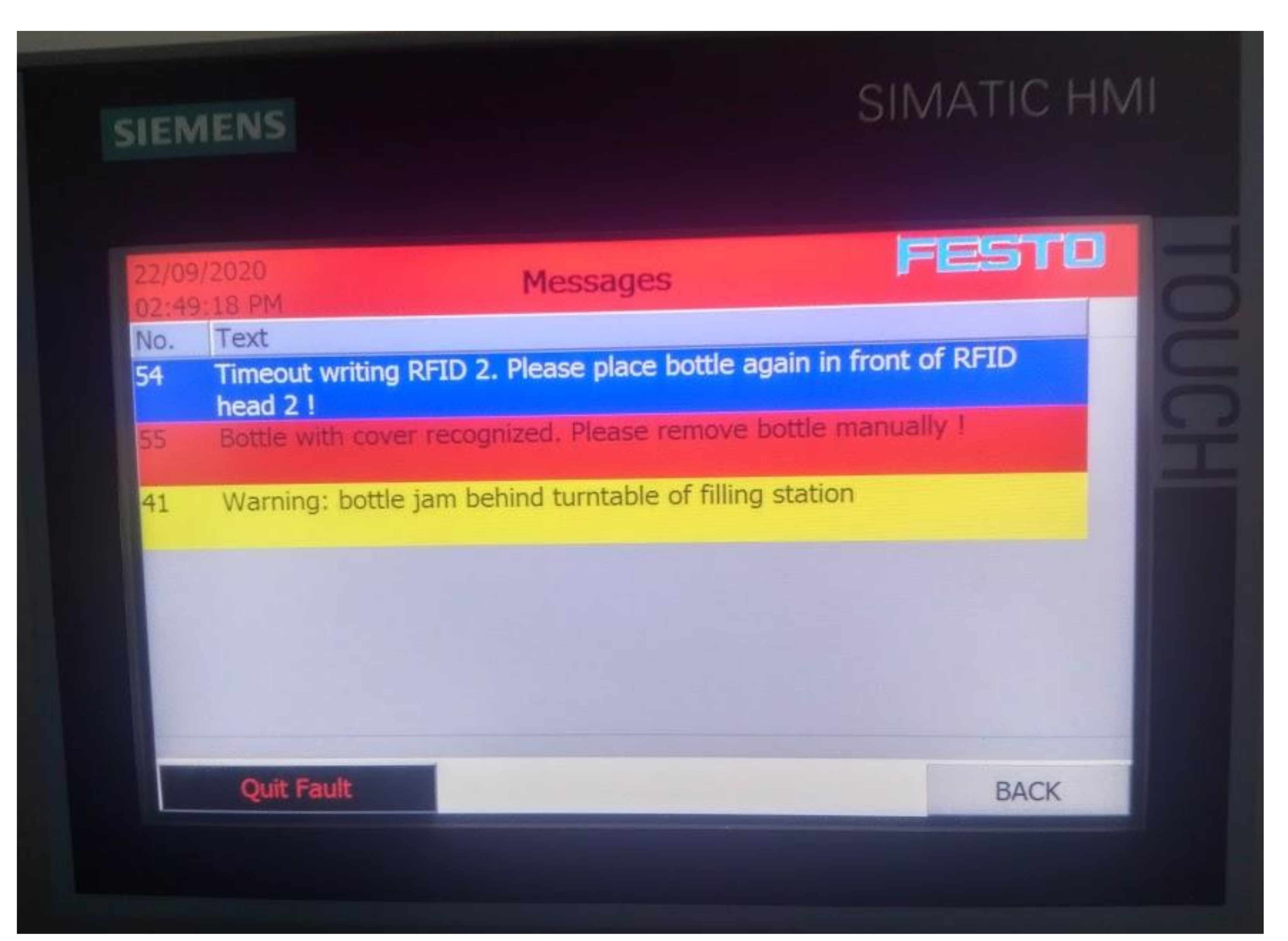
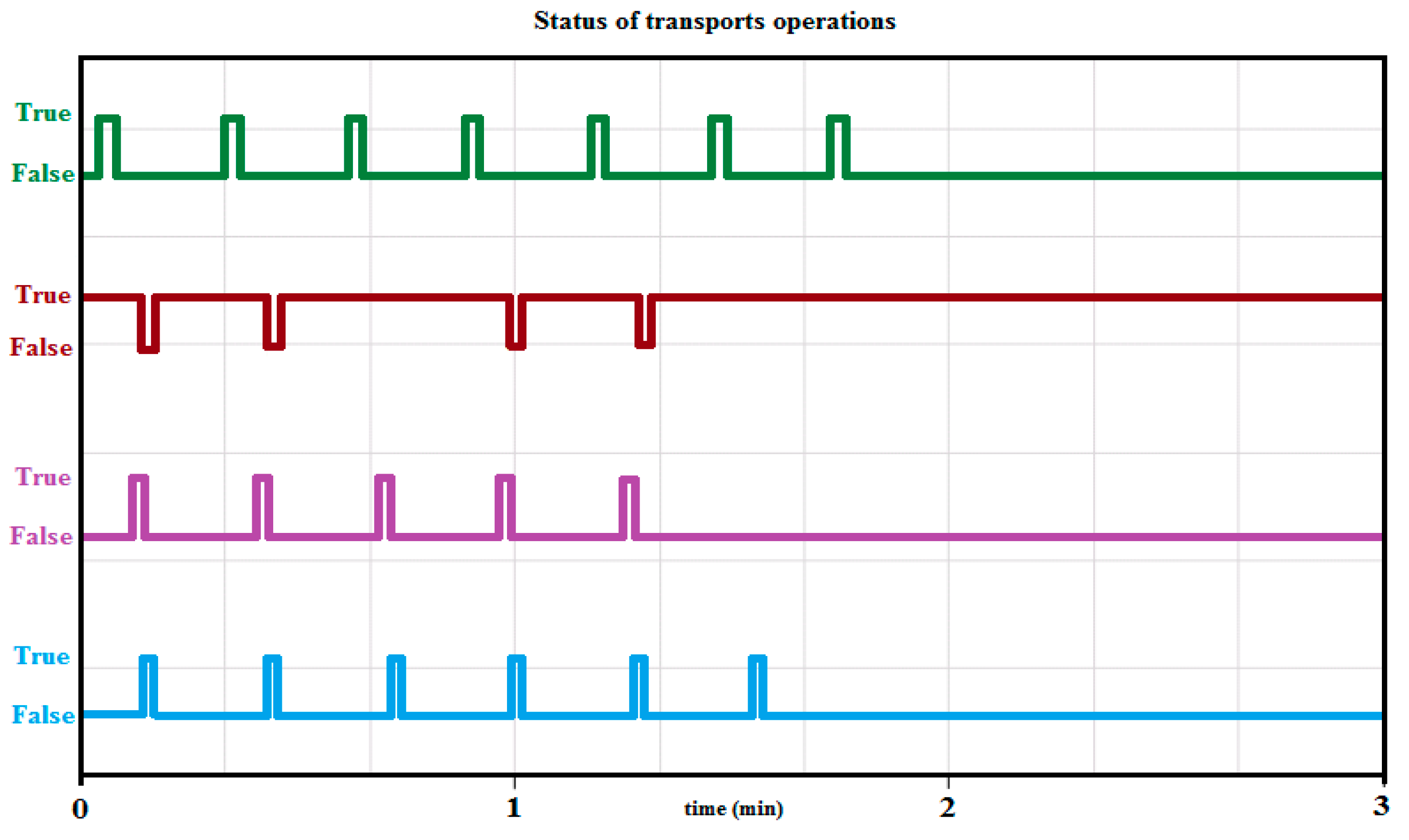
- The first serious problem in the production during the attack was the failure to transport the lid and storing it in the bottle. The carrier stopped in the middle of the track or did not complete the arm release operation when placing the lid on the bottle. At the same time, the production process was interrupted, which ensured the closing of the bottles. The production operators assumed that the occurred error was of mechanical origin, and error messages on the panels led them to misidentify the problem. A cap position placer sensor reported an error, as shown in Figure 10. The cause was the PLC unit of the lid carrier. The PLC, that controlled this operation and was hit by an attack, stopped working during the lifting of the lid while moving along the rail in the middle of the track. The operators started to solve the transport arm and its lubrication quality, as it looked as if the operation of moving along the rail always got stuck at the same point. The error message led the operators to incorrectly evaluate the reasons for the failure.
- RFID readers are used in the production line, where the second problem could be observed. It was created while reading RFID codes, which can also be seen in Figure 10. The attack caused the RFID reader at the Robot’s output to incorrectly read and sort the bottles because the signal to the sorting gate was missing. With this error, the expected exception occurred on the control panel, and the operators tried to start the production process by repeating the last step and reloading the data from the element that was reloaded by the RFID sensor. However, this approach did not lead to anything, and so the operators reported a hardware problem with the RFID reader. Each RFID sensor was prone to failure, and its error rate during the attack generated a large number of different alarms. If the RFID1 reader was hit at the inlet of the bottle into the production line and a reading timeout occurred, it was possible to observe the discharge of the wrong type of bottle, and another type of material was filled into an incompatible package. For example, granulate was dosed into the liquid container or vice versa. When the RFID2 output did not load the passing bottle, an alarm appeared that informed about the jamming of the rotary table of the filler. As this situation can realistically occur, the production operators tried to read the RFID code by manually attaching the bottle. In the case of high overflow, this activity was unsuccessful, and the operators’ assessment was an incorrect reader or an incorrectly set conveyor belt speed. Additional readers are installed in the recycling station, where the status at the input and output of the recycling station was incorrectly identified. Sometimes, the Robot did not run the material recycling action at all, and the contents were not soaked up, or the bottle did not open. This disrupted the work cycle.
- 3.
- The third problem arose when controlling the movement of the conveyor belt, where the PLC control unit ceased to be able to operate the drives. The result was a malfunction of the conveyor belt. Processed products could not be transported to the warehouse, and alarms were generated on the production line. The error, generated in this way, appeared to the operators as a technical failure of some component of the production line without a more precise specification. The operators determined that there was a problem with the power supply to the motors that provided the movement.
- 4.
- The camera, which was another element in the production line, was not able to read QR codes from the transport trolley. As the result, the conveyor belt was flooded with fully loaded pallets, and therefore, unloading and loading did not take place. The pallets were still running on the conveyor belt, but it was not until the monitor of unloading reported an error message, stating that no goods had been delivered in the last time interval. The operators again reported a hardware problem with the camera. These operations were usually visible in the MES system, and so the data provided by the Historian system were examined, where this type of problem manifested itself visibly on Scheme 6. Again, the operators deduced a hardware problem with the camera and later with the production line infrastructure. Specifically, the intention was to replace the switch. After exchanging for the same type after repeating the experiment, it was able to successfully implement this error again.
- 5.
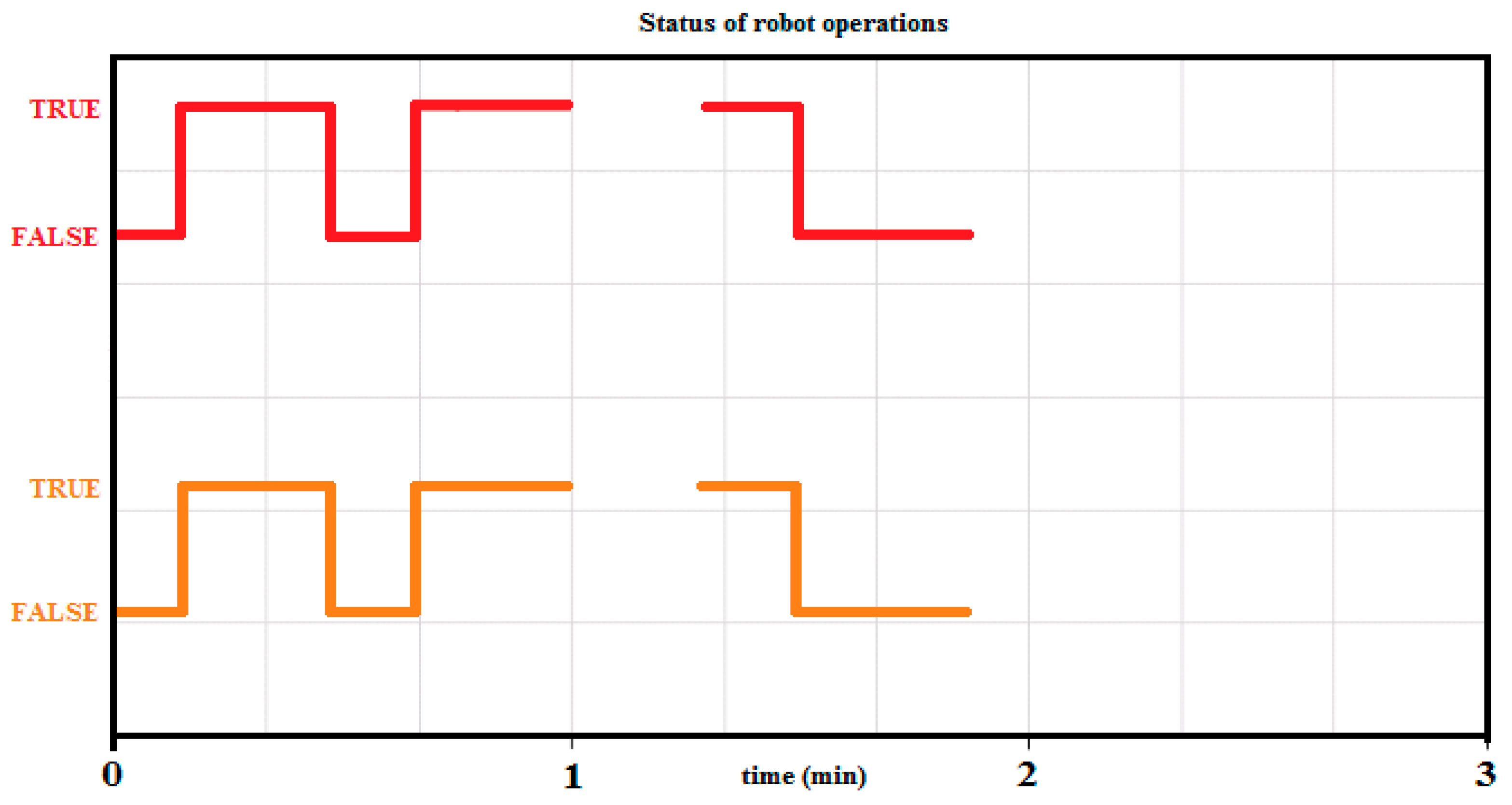
- The Robot and its PLC were very stable elements of the production line, and because of this, the result after attacking them was only slightly visible. One of the observed degradations was slowing the work down or jamming the Robot’s movement. The Robot and its control PLC failed only in a targeted attack on precisely specified ports and a defined UDP protocol. After the attack, the Robot stopped in the middle of the operation, but this moment could have occurred at any time. The Robot’s tools fell down, the recycling operation stopped, and the Robot stopped while the arm was moving.
- 6.
- The MES system was able to continue to perform the assigned task, but the problematic area was mainly data collection from the production line. In this case, there was the opportunity to analyze the behavior of the MES system, called Wonderware. The basic component that is responsible for data collection is the part of the Historian. This is divided into two sub-systems. The first sub-system takes care of the communication with the control elements of the production line. The second one is responsible for processing and writing data to a relational database, in this case—Microsoft SQL. During the attacks, it was possible to monitor changes in the quality of read data or their complete outages. These events were then interpreted by the MES system, and alarms were generated that could confuse production operators. A change in the quality of the collected data can be understood as their delayed processing, a change in the data parameters on the MES side of the system. Although the Wonderware implementation uses an internal protocol to ensure data delivery, the affected infrastructure has made it impossible to read real data, so the Historian only generated empty default data in the periodic cycles. In the case of loading error, it was possible to observe nonexistent values for the given parameters. Some outages were visible only with a considerable delay compared to the real state on the production line, as can be seen in Scheme 7.
- 7.
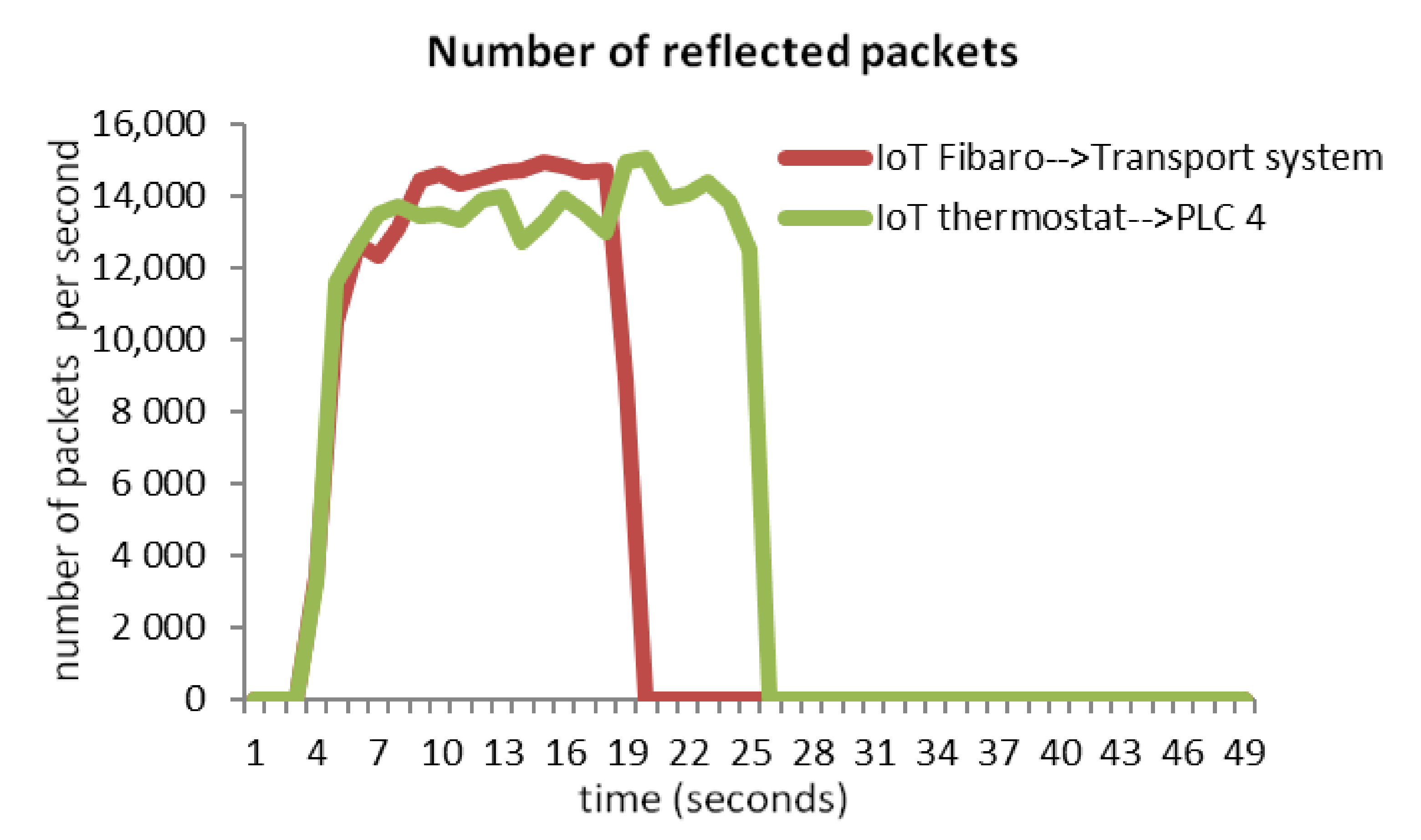
- All listed attack scenarios were later wrongly identified as hardware failures of individual production line components, or they were assessed as incorrectly entered production process parameters. The initial analysis of the problem, which relies only on monitoring the production process, was insufficient and led to incorrect conclusions. In the further search for failure, the components were randomly selected and, finally, a system and production line restart was performed. Even the monitoring of the infrastructure did not lead to the finding that it was an attack from the outside, as the reflected packets were visible in the network as packets that were generated by IoT devices. These were identified only with a delay, and also, they were first evaluated as a hardware error or incorrect configuration. For network monitoring, their behavior showed attributes of delicately used IP addresses or incorrectly set network parameters.
4. Discussion
Proposed Solutions to Mitigate the Effects of DDoS Attacks
- a source IP address
- a destination IP address
- a source port for UDP, TCP, and other protocols of 0
- a destination port for UDP, TCP, and ICMP of type and code, and for others, 0
- an IP protocol
- an IP type of service
- recording date and time
- an amount of data transferred.
- If it is necessary to make the IoT device freely available on the internet, its protection and isolation must be ensured by appropriate rules, which are defined in the firewall rules table. The firewall rules must be applied, if necessary, by using the proposed transparent bridge firewall.
- Performing analysis, mapping a network communication, and not relying only on the documentation that comes with the production line, for example, the method of mapping the network communication, as it was implemented in this study by using the net flow technique.
- Restriction of communication rules to what is necessary, if possible, within the production line.
- Ensure that the security systems that are used to protect devices are regularly updated to address potential security vulnerabilities to ensure the maximum possible removal of any known vulnerabilities.
- To include the network monitoring with data from the net flow and possibly detect any unusual activity during the production process.
- To specify whether IoT devices must necessarily provide data to the internet, or if it is possible to use another infrastructure and allow the integration into, for example, the intranet, where access is conditional like in a VPN connection, thus indirectly providing access to IoT devices.
5. Conclusions
Author Contributions
Funding
Conflicts of Interest
References
- Derhab, A.; Guerroumi, M.; Gumaei, A.; Maglaras, L.; Ferrag, M.A.; Mukherjee, M.; Khan, F.A. Blockchain and Random Subspace Learning-Based IDS for SDN-Enabled Industrial IoT Security. Sensors 2019, 19, 3119. [Google Scholar] [CrossRef] [Green Version]
- Bucci, G.; Ciancetta, F.; Fiorucci, E.; Fioravanti, A.; Prudenzi, A.; Mari, S. An IoT condition monitoring system for resilience based on spectral analysis of vibration. In Proceedings of the IEEE International Workshop on Metrology for Industry 4.0 & IoT, Roma, Italy, 10 July 2020; pp. 38–43. [Google Scholar] [CrossRef]
- Jiang, X.; Lora, M.; Chattopadhyay, S. An experimental analysis of security vulnerabilities in industrial IoT devices. ACM Trans. Internet Technol. 2020, 20, 1–24. [Google Scholar] [CrossRef]
- Sari, A.; Lekidis, A.; Butun, I. Industrial Networks and IIoT: Now and Future Trends. In Industrial IoT; Springer: Cham, Switzerland, 2020; pp. 3–55. [Google Scholar] [CrossRef]
- Prinsloo, J.; Sinha, S.; von Solms, B. A Review of Industry 4.0 Manufacturing Process Security Risks. Appl. Sci. 2019, 9, 5105. [Google Scholar] [CrossRef] [Green Version]
- Chhetri, S.R.; Rashid, N.; Faezi, S.; Al Faruque, M.A. Security trends and advances in manufacturing systems in the era of industry 4.0. In Proceedings of the IEEE/ACM International Conference on Computer-Aided Design (ICCAD), Irvine, CA, USA, 13–16 November 2017; pp. 1039–1046. [Google Scholar] [CrossRef]
- Tuptuk, N.; Hailes, S. Security of smart manufacturing systems. J. Manuf. Syst. 2018, 47, 93–106. [Google Scholar] [CrossRef]
- Frey, M.; Gündoğan, C.; Kietzmann, P.; Lenders, M.; Petersen, H.; Schmidt, T.C.; Wählisch, M. Security for the Industrial IoT: The case for information-centric networking. In Proceedings of the IEEE 5th World Forum on Internet of Things (WF-IoT), Limerick, Ireland, 15–18 April 2019; IEEE: Piscataway, NJ, USA; pp. 424–429. [Google Scholar] [CrossRef] [Green Version]
- Apiecionek, L.; Großmann, M.; Krieger, U.R. Harmonizing IoT-Architectures with Advanced Security Features-A Survey and Case Study. J. UCS 2019, 25, 571–590. [Google Scholar] [CrossRef]
- Knudsen, A.H.; Pedersen, J.M.; Sørensen, M.A.M.; Villumsen, T.D. Security in the Industrial Internet of Things, in Cybersecurity and Privacy: Bridging the Gap; River Publishers: Gistrup, Denmark, 2017; pp. 119–134. [Google Scholar]
- Shiaeles, S.N.; Katos, V.; Karakos, A.S.; Papadopoulos, B.K. Real time DDoS detection using fuzzy estimators. Comput. Secur. 2012, 31, 782–790. [Google Scholar] [CrossRef] [Green Version]
- Shiaeles, S.N.; Papadaki, M. FHSD: An Improved IP Spoof Detection Method for Web DDoS Attacks. Comput. J. 2015, 58, 892–903. [Google Scholar] [CrossRef] [Green Version]
- Siracusano, M.; Shiaeles, S.; Ghita, B. Detection of LDDoS attacks based on TCP connection parameters. In Proceedings of the Global Information Infrastructure and Networking Symposium (GIIS), Thessaloniki, Greece, 23–25 October 2018; pp. 1–6. [Google Scholar]
- Yan, Q.; Huang, W.; Luo, X.; Gong, Q.; Yu, F.R. A Multi-Level DDoS Mitigation Framework for the Industrial Internet of Things. IEEE Commun. Mag. 2018, 56, 30–36. [Google Scholar] [CrossRef]
- Saridou, B.; Shiaeles, S.; Papadopoulos, B. DDoS attack mitigation through Root-DNS Server: A case study. In Proceedings of the IEEE World Congress on Services (SERVICES), Milan, Italy, 8–13 July 2019; Volume 2642, pp. 60–65. [Google Scholar]
- Prathyusha, D.J.; Govinda, K. Analysis of Network Flow for Mitigation of DDoS Attacks in a Cloud Environment. In Embedded Systems and Artificial Intelligence; Springer: Singapore, 2020; pp. 835–841. [Google Scholar]
- Costa, W.L.; Silveira, M.M.; de Araujo, T.; Gomes, R.L. Improving DDoS Detection in IoT Networks Through Analysis of Network Traffic Characteristics. In Proceedings of the IEEE Latin-American Conference on Communications (LATINCOM), Santo Domingo, Dominican Republic, 18–20 November 2020; pp. 1–6. [Google Scholar]
- Manikumar, D.V.V.S.; Maheswari, B.U. Blockchain Based DDoS Mitigation Using Machine Learning Techniques. In Proceedings of the Second International Conference on Inventive Research in Computing Applications (ICIRCA), Coimbatore, India, 15–17 July 2020; pp. 794–800. [Google Scholar]
- Wang, B.; Zhang, X. Construction of Compound DDOS Network Security System Based on PKI and CA Authentication. In Data Processing Techniques and Applications for Cyber-Physical Systems (DPTA 2019), Proceedings of the DPTA 2019, Shanghai, China, 15–16 November 2019; Springer: Singapore, 2020; pp. 375–382. [Google Scholar]
- Vijayakumaran, C.; Muthusenthil, B.; Manickavasagam, B. A reliable next generation cyber security architecture for industrial internet of things environment. Int. J. Electr. Comput. Eng. 2020, 10, 387–395. [Google Scholar] [CrossRef]
- Dantas Silva, F.S.; Silva, E.; Neto, E.P.; Lemos, M.; Venancio Neto, A.J.; Esposito, F. A Taxonomy of DDoS Attack Mitigation Approaches Featured by SDN Technologies in IoT Scenarios. Sensors 2020, 20, 3078. [Google Scholar] [CrossRef]
- Sajid, A.; Abbas, H.; Saleem, K. Cloud-assisted iot-based scada systems security: A review of the state of the art and future challenges. IEEE Acc. 2016, 4, 1375–1384. [Google Scholar] [CrossRef]
- Boyes, H.; Hallaq, B.; Cunningham, J.; Watson, T. The industrial internet of things (IIoT): An analysis framework. Comput. Ind. 2018, 101, 1–12. [Google Scholar] [CrossRef]
- Younan, M.; Houssein, E.H.; Elhoseny, M.; Ali, A.A. Challenges and recommended technologies for the industrial internet of things: A comprehensive review. Measurement 2019, 151, 107198. [Google Scholar] [CrossRef]
- Sha, L.; Xiao, F.; Chen, W. IIoT-SIDefender: Detecting and defense against the sensitive information leakage in industry IoT. World Wide Web 2018, 21, 59–88. [Google Scholar] [CrossRef]
- Bettayeb, M.; Waraga, O.A.; Talib, M.A.; Nasir, Q.; Einea, O. IoT Testbed Security: Smart Socket and Smart Thermostat. In Proceedings of the IEEE Conference on Application, Information and Network Security (AINS), Pulau Pinang, Malaysia, 19–21 November 2019; pp. 18–23. [Google Scholar] [CrossRef]
- Özgür, L.; Akram, V.K.; Challenger, M.; Dağdeviren, O. An IoT based smart thermostat. In Proceedings of the 5th International Conference on Electrical and Electronic Engineering (ICEEE), Istanbul, Turkey, 3–5 May 2018; pp. 252–256. [Google Scholar] [CrossRef]
- Liou, J.C.; Jain, S.; Singh, S.R.; Taksinwarajan, D.; Seneviratne, S. Side-channel information leaks of Z-wave smart home IoT devices: Demo abstract. In Proceedings of the 18th Conference on Embedded Networked Sensor Systems (SenSys’20), Virtual Event, Japan, 16–19 November 2020; Association for Computing Machinery: New York, NY, USA, 2020; pp. 637–638. [Google Scholar] [CrossRef]
- Kaderabek, J. Integration of Fibaro system to intruder and hold-up alarm systems. In Proceedings of the 16th International Scientific Conference Engineering for Rural Development, Jelgava, Latvia, 24–26 May 2017; pp. 1080–1085. [Google Scholar] [CrossRef]
- Xu, Y.; Liu, Y. DDoS Attack Detection Under SDN Context. In Proceedings of the IEEE INFOCOM 2016—The 35th Annual IEEE International Conference on Computer Communications, San Francisco, CA, USA, 10–14 April 2016; pp. 1–9. [Google Scholar] [CrossRef]
- Manso, P.; Moura, J.; Serrão, C. SDN-Based Intrusion Detection System for Early Detection and Mitigation of DDoS Attacks. Information 2019, 10, 106. [Google Scholar] [CrossRef] [Green Version]
- Yuan, X.; Li, C.; Li, X. DeepDefense: Identifying DDoS attack via deep learning. In Proceedings of the IEEE International Conference on Smart Computing (SMARTCOMP), Hong Kong, China, 29–31 May 2017; pp. 1–8. [Google Scholar] [CrossRef]
- Hoque, N.; Bhattacharyya, D.; Kalita, J. Botnet in DDoS Attacks: Trends and Challenges. IEEE Commun. Surv. Tutor. 2015, 17, 2242–2270. [Google Scholar] [CrossRef]
- Bawany, N.; Shamsi, J.; Salah, K. DDoS Attack Detection and Mitigation Using SDN: Methods, Practices, and Solutions. Arab. J. Sci. Eng. 2017, 42. [Google Scholar] [CrossRef]
- Lukaseder, T.; Stölzle, K.; Kleber, S.; Erb, B.; Kargl, F. An SDN-based Approach for Defending Against Reflective DDoS Attacks. In Proceedings of the IEEE 43rd Conference on Local Computer Networks (LCN), Chicago, IL, USA, 1–4 October 2018; pp. 299–302. [Google Scholar] [CrossRef] [Green Version]
- Vlajic, N.; Zhou, D. IoT as a Land of Opportunity for DDoS Hackers. Computer 2018, 51, 26–34. [Google Scholar] [CrossRef]
- Sharafaldin, I.; Lashkari, A.H.; Hakak, S.; Ghorbani, A.A. Developing realistic Distributed Denial of Service (DDoS) attack dataset and taxonomy. In Proceedings of the International Carnahan Conference on Security Technology (ICCST), Chennai, India, 1–3 October 2019; pp. 1–8. [Google Scholar] [CrossRef]
- Kolahi, S.S.; Treseangrat, K.; Sarrafpour, B. Analysis of UDP DDoS flood cyber attack and defense mechanisms on Web Server with Linux Ubuntu 13. In Proceedings of the International Conference on Communications, Signal Processing, and their Applications (ICCSPA’15), Sharjah, United Arab Emirates, 17–19 February 2015. [Google Scholar] [CrossRef]
- Barki, L.; Shidling, A.; Meti, N.; Narayan, D.G.; Mulla, M.M. Detection of Distributed Denial of Service Attacks in Software Defined Networks. In Proceedings of the International Conference on Advances in Computing, Communications and Informatics (ICACCI), Jaipur, India, 21–24 September 2016. [Google Scholar] [CrossRef]
- Kumar, P.; Tripathi, M.; Nehra, A.; Conti, M.; Lal, C. SAFETY: Early Detection and Mitigation of TCP SYN Flood Utilizing Entropy in SDN. IEEE Trans. Netw. Serv. Manag. 2018, 15, 1545–1559. [Google Scholar] [CrossRef]
- Mohammadi, R.; Javidan, R.; Conti, M. Slicots: An sdn-based lightweight countermeasure for tcp syn flooding attacks. IEEE Trans. Netw. Serv. Manag. 2017, 14, 487–497. [Google Scholar] [CrossRef]
- Gurina, A.; Eliseev, V. Anomaly-Based Method for Detecting Multiple Classes of Network Attacks. Information 2019, 10, 84. [Google Scholar] [CrossRef] [Green Version]
- Galeano-Brajones, J.; Carmona-Murillo, J.; Valenzuela-Valdés, J.F.; Luna-Valero, F. Detection and Mitigation of DoS and DDoS Attacks in IoT-Based Stateful SDN: An Experimental Approach. Sensors 2020, 20, 816. [Google Scholar] [CrossRef] [Green Version]
- Chandel, S.; Yang, G.; Chakravarty, S. AES–CP–IDABE: A Privacy Protection Framework against a DoS Attack in the Cloud Environment with the Access Control Mechanism. Information 2020, 11, 372. [Google Scholar] [CrossRef]
- Polat, H.; Polat, O.; Cetin, A. Detecting DDoS Attacks in Software-Defined Networks Through Feature Selection Methods and Machine Learning Models. Sustainability 2020, 12, 1035. [Google Scholar] [CrossRef] [Green Version]
- Bhandari, A.; Sangal, A.L.; Kumar, K. Characterizing flash events and distributed denial-of-service attacks: An empirical investigation. Secur. Commun. Netw. 2016, 9, 2222–2239. [Google Scholar] [CrossRef] [Green Version]
- Mystkowski, A.; Kierdelewicz, A. Fractional-Order Water Level Control Based on PLC: Hardware-In-The-Loop Simulation and Experimental Validation. Energies 2018, 11, 2928. [Google Scholar] [CrossRef] [Green Version]
- Xiao, Y.; Yin, J.; Hu, Y.; Wang, J.; Yin, H.; Qi, H. Monitoring and Control in Underground Coal Gasification: Current Research Status and Future Perspective. Sustainability 2019, 11, 217. [Google Scholar] [CrossRef] [Green Version]
- Vaclavova, A.; Kebisek, M. Design of Virtual Model of Production Line Using Wonderware ArchestrA. In Proceedings of the IEEE 22nd International Conference on Intelligent Engineering Systems (INES), Las Palmas de Gran Canaria, Spain, 21–23 June 2018; pp. 000425–000430. [Google Scholar] [CrossRef]
- Vaclavova, A.; Kebisek, M. Integration of production line with the Wonderware platform. In Software Engineering and Algorithms in Intelligent Systems; Springer: Cham, Switzerland, 2018; pp. 208–215. [Google Scholar] [CrossRef]
- Panarello, A.; Tapas, N.; Merlino, G.; Longo, F.; Puliafito, A. Blockchain and IoT Integration: A Systematic Survey. Sensors 2018, 18, 2575. [Google Scholar] [CrossRef] [Green Version]
- Tempest. Production Line Description: User Manual; Tempest: Ashland, OH, USA, 2014. [Google Scholar]
- Mohammed, W.M.; Ferrer, B.R.; Iarovyi, S.; Negri, S.; Fumagalli, N.; Lobov, A.; Lastra, J.L.M. Generic platform for manufacturing execution system functions in knowledge-driven manufacturing systems. Int. J. Comput. Integr. Manuf. 2018, 31, 262–274. [Google Scholar] [CrossRef]
- Yee, I.; Eren, H. Data Historian. In Instrument Engineers’ Handbook: Process Software and Digital Networks; CRC Press (Taylor and Francis Group): Boca Raton, FL, USA, 2011; pp. 454–464. [Google Scholar]
- Erickson, B.; Manushree, A.; Naryzhny, Y.; Kamath, V.; Lie, C.; Middleton, E. Replicating Time-Series Data Values for Retrieved Supervisory Control and Manufacturing Parameter Values in a Multi-Tiered Historian Server Environment. U.S. Patent 8,676,756, 18 March 2014. [Google Scholar]
- Patel, R.J.; Mahesuria, G.; Panchal, P.; Panchal, R.; Sonara, D.; Tanna, V.; Pradhan, S. Implementation of time synchronized cryogenics control system network architecture for SST-1. Fus. Eng. Des. 2016, 112, 747–751. [Google Scholar] [CrossRef]
- Shipunov, M.V.; Grachev, V.V.; Myshlyaev, L.P.; Ivushkin, K.A.; Fayrushin, S.A.; Makarov, G.V. Creation of a control automation system on the example of the coal processing plant. In IOP Conference Series: Materials Science and Engineering; IOP Publishing: Bristol, UK, 2020. [Google Scholar] [CrossRef]
- Horák, T.; Šimon, M.; Huraj, L.; Budjač, R. Vulnerability of Smart IoT-Based Automation and Control Devices to Cyber Attacks. In Computer Science On-Line; Springer: Cham, Switzerland, 2020; pp. 287–294. [Google Scholar] [CrossRef]
- Liang, L.; Zheng, K.; Sheng, Q.; Huang, X. A Denial of Service Attack Method for an IoT System. In Proceedings of the 8th International Conference on Information Technology in Medicine and Education (ITME), Fuzhou, China, 23–25 December 2016; pp. 360–364. [Google Scholar] [CrossRef]


| Research | Method | Description |
|---|---|---|
| S.N. Shiaeles, et al., 2012 [11] | DDoS detection using fuzzy estimators | detecting a DDoS and identifying the malicious IPs |
| S.N. Shiaeles, et al., 2015 [12] | fuzzy hybrid spoofing detector | based on source MAC address, hop count, GeoIP, OS passive fingerprinting, and web browser user agent |
| M. Siracusano, et al., 2018 [13] | detection of LDDoS attacks | based on characteristics of malicious TCP flows |
| Q. Yan et al., 2018 [14] | DDoS mitigation | a multi-level DDoS mitigation framework for IIoT including the edge computing level, fog computing level, and cloud computing level |
| B. Saridou, et al., 2019 [15] | DDoS mitigation | a machine learning-based system promoting high availability of DNS services during DDoS attacks |
| D.J. Prathyusha and K. Govinda 2020 [16] | DDoS mitigation | based on network flow analysis at the targeted side against virtual services |
| W.L. Costa, et al., 2020 [17] | DDoS detection | detection mechanism based on machine learning |
| D.V.V.S. Manikumar and B.U. Maheswari 2020 [18] | DDoS mitigation | system uses machine learning algorithms to identify the incoming packet and uses blockchain technology to store the blacklist |
| B. Wang and X. Zhang 2020 [19] | DDoS mitigation | defense strategy based on dynamic IP packet filtering technology |
| Position | Station | Controller |
|---|---|---|
| 1 | Unpackaging station | PLCS7-314C |
| 2 | Bottling station touch panel | Touch panel |
| 3 | Robot station recycling | PLCS7-314C/Port 1200 |
| Robot | Drive Unit/Port 10,001 | |
| 4 | Distribution station | PLCS7-314C |
| 5 | Buffer station | PLCS7-314C |
| 6 | Handling station | PLCS7-314C |
| 7 | Bottling station | PLCS7-314C |
| 8 | Filtration | PLCS7-314C |
| 9 | Mixing | PLCS7-314C |
| 10 | Reactor | PLCS7-314C |
| 11 | Bottling | PLCS7-314C |
| 12 | Quality control | PLCS7-314C |
| 13 | Vibration conveyor | PLCS7-314C |
| 14 | Dosage | PLCS7-314C |
| 15 | IN/OUT station | PLCS7-314C |
| 16 | AS/RS station touch panel | Touch panel |
| 17 | Packaging station Camera | PLCS7-314C |
| 18 | AS/RS station | PLCS7-314C |
| 19 | Transport system | PLCS7-314C |
| 20 | Switch | Hub |
| 21 | PC Control WIN CC | MS Windows |
| 22 | PC Control MES | MS Windows |
| Scenario | Type of Attack | Attack |
|---|---|---|
| Scenario 1 | Reflected (DRDoS) | ICMP flood |
| Scenario 2 | Reflected (DRDoS) | ICMP flood |
| Scenario 3 | Reflected (DRDoS) | UDP flood |
| Scenario 4 | Direct (DDoS) | TCP SYN flood |
| Scenario 5 | Direct (DDoS) | TCP ACK flood |
| Rule Description | Rule Definition |
|---|---|
| default rules check established, related | -F FORWARD -P FORWARD DROP -A FORWARD -s 0.0.0.0/0.0.0.0 -d 0.0.0.0/0.0.0.0 -m state --state INVALID -j DROP |
| enable DHCP UDP packets if needed | -A FORWARD -p udp --dport=67:68 --sport=67:68 -J ACCEPT |
| Limit ICMP | -A FORWARD -p icmp -m limit --limit 4/s -j ACCEPT |
| Rule description | Rule definition |
| Force SYN packets check | -A FORWARD -p tcp ! --syn -m state --state NEW -j DROP -A FORWARD -p icmp --icmp-type 8 -d 0/0 -m state --state NEW,ESTABLISHED,RELATED -j ACCEPT -A FORWARD -p icmp --icmp-type 0 -s 0/0 -m state --state ESTABLISHED,RELATED -j ACCEPT |
| Reject spoofed packets | -A FORWARD -s 10.0.0.0/8 -j DROP -A FORWARD -s 169.254.0.0/16 -j DROP -A FORWARD -s 172.16.0.0/12 -j DROP -A FORWARD -s 127.0.0.0/8 -j DROP -A FORWARD -s 224.0.0.0/4 -j DROP -A FORWARD -d 224.0.0.0/4 -j DROP -A FORWARD -s 240.0.0.0/5 -j DROP -A FORWARD -d 240.0.0.0/5 -j DROP -A FORWARD -s 0.0.0.0/8 -j DROP -A FORWARD -d 0.0.0.0/8 -j DROP -A FORWARD -d 239.255.255.0/24 -j DROP -A FORWARD -d 255.255.255.255 -j DROP |
| Stop smurf attacks | -A FORWARD -p icmp -m icmp --icmp-type address-mask-request -j DROP -A FORWARD -p icmp -m icmp --icmp-type timestamp-request -j DROP -A FORWARD -p icmp -m icmp -j DROP |
| Drop all invalid packets | -A FORWARD -m state --state INVALID -j DROP -A FORWARD -m state --state INVALID -j DROP -A FORWARD -m state --state INVALID -j DROP |
| Block sync flood | -N udp-flood -A FORWARD -p udp -j udp-flood -A udp-flood -p udp -m limit --limit 50/s -j RETURN -A udp-flood -j LOG --log-level 4 --log-prefix ‘UDP-flood: ‘ -A udp-flood -j DROP |
| Enable other traffic which is needed—ssh/web | -A FORWARD -p tcp -s 0.0.0.0/0 -d X.X.X.X/32 --dport 80 -j ACCEPT -A FORWARD -p tcp -s 0.0.0.0/0 -d X.X.X.X/32 --dport 22 -j ACCEPT |
Publisher’s Note: MDPI stays neutral with regard to jurisdictional claims in published maps and institutional affiliations. |
© 2021 by the authors. Licensee MDPI, Basel, Switzerland. This article is an open access article distributed under the terms and conditions of the Creative Commons Attribution (CC BY) license (http://creativecommons.org/licenses/by/4.0/).
Share and Cite
Horak, T.; Strelec, P.; Huraj, L.; Tanuska, P.; Vaclavova, A.; Kebisek, M. The Vulnerability of the Production Line Using Industrial IoT Systems under DDoS Attack. Electronics 2021, 10, 381. https://doi.org/10.3390/electronics10040381
Horak T, Strelec P, Huraj L, Tanuska P, Vaclavova A, Kebisek M. The Vulnerability of the Production Line Using Industrial IoT Systems under DDoS Attack. Electronics. 2021; 10(4):381. https://doi.org/10.3390/electronics10040381
Chicago/Turabian StyleHorak, Tibor, Peter Strelec, Ladislav Huraj, Pavol Tanuska, Andrea Vaclavova, and Michal Kebisek. 2021. "The Vulnerability of the Production Line Using Industrial IoT Systems under DDoS Attack" Electronics 10, no. 4: 381. https://doi.org/10.3390/electronics10040381