Article

A Real-Time Matrix Iterative Optimization Algorithm of Booking Elevator Group and Numerical Simulation Formed by Multi-Sensor Combination

1
School of Mathematics and Statistics, Wuhan University, Wuhan 430072, China
2
Commerical Vehicle Technology Center of SAIC Motor Group Co., Ltd., Shanghai 200433, China
3
Faculty of Science, Northeast University, Qinhuangdao 110819, China
4
Department of Civil and Environmental Engineering, The University of Auckland, Auckland 1010, New Zealand
5
School of Computer Science, The University of Auckland, Auckland 1010, New Zealand
*
Author to whom correspondence should be addressed.
Electronics 2021, 10(24), 3179; https://doi.org/10.3390/electronics10243179
Submission received: 16 November 2021 / Revised: 14 December 2021 / Accepted: 14 December 2021 / Published: 20 December 2021
(This article belongs to the Section Systems & Control Engineering)

Abstract

:
Elevators are an essential indoor transportation tool in high-rise buildings. The world is advocating the design concept of safety, energy-saving, and intelligence. We focus on improving operation speed and utilization efficiency of the elevator group. This paper proposed a real-time reservation elevator groups optimization algorithm, and a dynamic matrix iterative model has been established. The indoor navigation technology UWB is applied, which can help users to quickly find elevators. The manned equilibrium efficiency and running time equilibrium efficiency of elevator group are given. Moreover, the data filtering criterion formulas for user waiting time and elevator remaining space are defined. In this paper, three numerical examples are given. Example 1 is a single elevator in n-storey building. Example 2 is compared with different scheduling algorithms, such as FCFS, SSTF, LOOK, and SCAN algorithms, and the results show that our method has the advantages of short total running time and less round-trip frequency. At last, the matrix of numerical iteration results are visualized, and the data movement status of people on each floor can be observed. Example 3 introduced elevator group algorithms. For high-rise buildings, this paper adopts a high, medium, and low hierarchical management model; this model has high coordination, as well as fast response, batch process, and adaptive function. Finally, we also discussed and compared the complexity of single elevator and elevator group algorithms. Therefore, this method has great development potential and practical application value, which deserves further study.

Highlights

  • This paper proposes a real-time matrix iteration optimization algorithm, using a matrix to describe the elevator’s operation condition. Our algorithm improves the utilization rate, reducing waiting time, having less total running time, and having low round-trip frequency, when compared with the other four methods.
  • A reservation elevator software has been designed in this paper. So, there is no need to touch the button in this way, which can avoid the chance of spreading bacteria. The manned equilibrium efficiency and running time equilibrium efficiency of elevator group are given.
  • Application face recognition can improve algorithm stability. Increasing indoor navigation UWB technology can help users to quickly find nearby elevators. In addition, waiting time and elevator remaining space data filtering criteria formulas are given.
  • For super high-rise buildings, this paper adopts a hierarchical management model, which can improve coordination and operation speed. Finally, the computational complexity of a single elevator and an elevator group are compared.

1. Introduction

1.1. Research Motivation and Significance

Elevators are an essential indoor transportation tool in public areas, such as people going shopping, learning at the library, sightseeing elevators, and other public activities. However, there are still many aspects of traditional elevators that need to be improved and optimized, such as the number of elevators at the peak of work is insufficient, elevator overload will easily cause safety accidents and the unfair distribution of tasks causes waste of power resources, etc. There are already many elevator scheduling algorithms, and the utilization efficiency and operating speed are improving.
In view of the above reasons, this paper focuses on the optimization algorithm of elevator group. The purpose is to simplify the operation mode, to have the characteristics of diversity, and to solve the various problems encountered by users in use. We change the research thinking, obtain accurate data through the reservation method, and provide a reliable foundation for the optimization model and obtain sufficient optimization decision-making time. This paper aims to show that the established mathematical model can improve the coordination and utilization of elevators, reduce the elevator round trip batches, and reduce the waiting time of users. The ultimate goal is to save energy and improve the comfort of users, as well as promote the construction of smart cities in the new era. The road to the happiness of science and technology is for the benefit of humanity.

1.2. Related Work

The scheduling algorithm has a wide range of applications, not only in elevators but also in computer hard disk, transportation, express transportation, and wireless networks [1,2,3]. The current common elevator scheduling algorithms include FCFS (First Come First Serve), SCAN, LOOk algorithm, SSTF (Shortest Seek Time First), SATF (Shortest Access Time First), etc., [4,5,6,7]. The advantages of FCFS algorithm are fairness, early call, and early response. The defect is that the elevator has a high frequency of round trip and low utilization rate. The program of SCAN algorithm is stable and simple, and it is round trip at the lowest floor and highest floor. The defect is that no-load is serious, and energy is wasted. LOOK is wiser than the SCAN algorithm, and the elevator only reaches the minimum and maximum values of the call floor. SSTF and SATF belong to local optimization, without overall planning. In addition, the above algorithm is mainly for low floors and low crowd density. It does not consider the balance between the waiting time and the overall operating efficiency. These factors will affect the user’s satisfaction and the total operating time of the elevator. So, the short time-consuming algorithm is still being explored.
In recent years, elevator group optimization algorithms have been constantly improving, and the research trends have shifted to multidisciplinary applications, multi-angle modeling, and simulation experiments. The scheduling problem can be solved from statistics and graph theory. The number of people taking the elevator has different characteristics in different locations. Of course, there are special circumstances, such as training institutions, movie theaters, rush hour, etc., where the inflow rate of users into elevators varies periodically with time. Passenger flow can be predicted by the support vector machine (SVM) method and fuzzy information granulation (FIG) method [8]. Deep learning can learn and predict the parking position of the elevator and the remaining space of the elevator. A search model is built to solve dispatching optimization [9]. The elevators can be described by the nonlinear-map model. Using this method can obtain the return map for inflow rate and its period [10]. Another elevator scheduling algorithm can be combined with the Monte Carlo method for simulation. For the DGC (Destination Group Control) system, the value of the elevator round trip time can be calculated under destination group control using (the highest reversal floor) and S (the expected number of stops in a round trip) [11]. In literature [12], with the help of order statistics, round-trip time estimation of the 2D or 3D system analytically estimated, this method can also be verified by Monte Carlo simulation.
Furthermore, improving the utilization rate of elevator groups has been a research hotspot in the field of elevator optimization. The total energy consumed by the elevator each year is also a large expense [13,14]. The elevator scheduling algorithm can also be optimized according to the energy method. This method same need to predict the energy and power consumption of elevators or simulated movement of occupants [15]. Moreover, the Robust Optimization Scheduling Model is built to handle elevators by energy under uncertain up-peak traffic flow [16]. In addition, the elevator scheduling algorithm can also be controlled according to fuzzy logic theory. An elevator group control system based on fuzzy logic method (FEGCS) is mainly choosing the best plan from the local control system (LCS) as the execution strategy in order to reduce the user waiting time and the power consumption [17]. The elevator group controller based on the fuzzy logic framework, using average waiting time (AWT) as a performance metric, requires a wealth of experience to adjust the appropriate membership function and select the appropriate fuzzy rule set to generate appropriate control actions [18,19]. Particle swarm optimization (PSO) algorithm has been applied to elevator group control systems, which is a technique used to serve skyscrapers during peak traffic. The defect of this algorithm is that it is easy to fall into local extreme points, and it is difficult to obtain high-precision numerical solutions [20]. Genetic algorithm has also been introduced into the field of elevator scheduling algorithms [21,22,23]; a single genetic algorithm code cannot fully constrain the optimization problem, and it has the phenomenon of early convergence.
The traditional elevator has some problems, such as a long time to solve, there are multiple models in different scenarios, and the utilization rate is not high. The main influencing factors are the uncertain number of users waiting to take the elevator, inaccurate estimation of the number of people inside the elevator, and destination floor number input error that cannot be corrected in time. The above factors make it difficult to optimize the best assignment plan. The non-booking model can only use historical data to predict or the accumulated experience to obtain the results with lag, and it is difficult to optimize the most accurate results in real-time. Given this, this article proposes an elevator reservation model. The most significant advantage is that the most accurate data is obtained in advance, which is conducive to planning the best task scheduling strategy. In fact, the ideas and advantages of scheduling appointments have been gradually discovered and applied in real life, for example, Cloud manufacturing (CMfg) [24], outpatient medical appointments [25], immediate ride-hailing service [26], etc. However, the booking scheduling algorithms are currently in the exploratory stage, which is the significance and innovative value of research.

1.3. Contributions

This paper focuses on improving the user-friendly, speed, and efficiency of the elevator groups, and our main contributions have five points. Firstly, we created two ways to take the elevator: long-distance APP booking and on-site entry elevator reservation system, which reduced waiting time. Traditional elevator algorithms need to predict the flow of people, but our method collects data by user’s reservation so that we can obtain more accurate data. The second contribution is that this paper proposed a real-time reservation elevator group optimization algorithm. A dynamic matrix iterative model is established. This model balances the waiting time and overall operating efficiency. Pre-allocate tasks can reduce the number of round trips and improve elevator utilization. Thirdly, the manned equilibrium efficiency and running time equilibrium efficiency of elevator group are given. Fourthly, for super high floors, we have proposed a hierarchical management model. The elevator group algorithms are flexible, coordinated with each other, adaptively start the number of elevators, and have the function of automatically preventing overload. The last contribution is that the addition of face recognition technology and indoor navigation not only facilitates users finding elevators quickly but also promotes indoor commercial applications. Mature face recognition technology can also improve the reliability of elevator safe operation.

1.4. Structure and Framework of This Paper

This article consists of four parts. Section 2 introduces the model theory of matrix iterative optimization algorithm theory. Meanwhile, the principle of solving the least square solution of the indoor navigation algorithm UWB is given. In addition, we also proposed an equilibrium mechanism of priority order and users satisfaction. This part explains in detail how the elevator automatically prevents overloading. Section 3 mainly introduces three numerical examples and compares them with other algorithms. Numerical experiments include single elevator, double elevator, and elevator group. Section 4 is mainly a discussion and summary. We discuss the relationship and complexity of single elevator and elevator group and summarize the contribution of this article and important research conclusions.

2. Mathematical Model and Application Design of Booking Elevators

2.1. Variable Interpretation

This paper mainly studies the real-time elevator group optimization algorithm.
The multiple models established in this paper, such as the estimation model of user’s movement time based on indoor navigation, and the time judgment standard model is defined. Furthermore, the automatic load limit iteration model of the elevator is proposed. Again, these model functions can help the time pre-processing and space pre-processing to filter data, the comparison and connection of the complexity of single elevator and elevator group are discussed, etc. These models use multiple matrices and multiple functional variables. To facilitate the reader’s understanding, this section gives the most critical variable explanation; the details are as follows in Table 1.

2.2. Single Elevator Booking Model

The reservation model is widely used in real-life scheduling problems [27,28,29]. The solution steps of this model are carried out in the following order: the data collection must be completed first and then perform data pre-processing, bring in the optimization model to solve, and, finally, visualize the results. The leading theory of the algorithm includes five parts: reservation data collection, the priority of nearest principle combined with time constraints, real-time matrix movement iteration method, and matrix visualization.

2.2.1. Booking Data Collection

Passengers can scan the QR code or download the official App in advance near the mall and make an appointment 10–120 s in advance. Users are required to submit some primary information when they are first registered, and next time only need to fill in the destination floor. The preliminary information includes the starting floor (The system automatically fills in the starting floor when scanning the QR code.), the destination floor number, and the number of passengers. The system automatically records the submission time. We have already designed the default software system, and the design interface and registration information are shown in Figure 1 and Figure 2.
Moreover, recent personal photos should be uploaded (change it every six months), with some basic information, including height, weight, opening Bluetooth. So, a one-to-one relationship has been established between reservation information and users. This purpose is that the system can detect whether the reserved person has entered the elevator. If face matching fails, we can use basic information to make the second judgment. If only one passenger, please submit data directly. If many passengers are going to the same destination, each of them can submit their companions’ information.

2.2.2. Application of Indoor UWB Navigation

Indoor positioning can use high-precision Ultra-Wide Band (UWB) pulse technology. UWB positioning technology is currently the most accurate (10 cm), which is close to laser positioning, but the cost is lower. Adding UWB navigation to the APP that can help users to find the nearest elevator can also estimate the time from the submission [30,31]. The countdown function reminds users how much time of this reservation is left. If users do not enter the elevator at the scheduled time, the system will automatically clean this data. Adding the time limit can improve the operating efficiency and safety factor of the elevator. The following three are more commonly used in UWB positioning: TOA (time of arrival) is determined by the signal propagation from the mobile terminal to more than three base stations, AOA (angle of arrival) based on direction angle, and TDOA (time difference of arrival) based on the time difference. The definitions of TOA, AOA, and TDOA are as follows:
TOA: Using the principle of triangulation, the distance between the signal source and different base stations can be located. TOA estimates the distance by measuring the delay from the base station to the tag.
AOA: According to the phase difference when the signal arrives at different antennas and the distance between the two antennas, the angle between the two antennas at different base stations and the signal can be measured. From a plane perspective, the signal source can be located. The technique of positioning by an angle is called the angle of arrival.
TDOA: This method is to calculate the distance between the two based on the time difference between the transmission and reception of a radio wave. The signal has a different time to different reference base stations, which means different distances so that the specific location can be measured. There is strict time synchronization between the base station and the tag, but the signal source complexity is low. Now, the following will give a detailed description of the solution process of a TDOA positioning algorithm.
The principle of TDOA positioning is given in this section. The TDOA positioning algorithm requires that each base station maintain time synchronization, which can reach within 0.1 ns . The synchronization accuracy of UWB base stations is very accurate [32]. The mobile tag (mobile phone) signal is transmitted to the i-th base station, which takes the time t i , and the time to the first base station is recorded as t 1 , while c is the electromagnetic wave propagation speed. Therefore, the distance difference between the mobile tag to the i-th base station and the first base station is recorded as r i 1 .
r i 1 = c t i t 1 .
An indoor movement time estimation model based on the TDOA algorithm is established. We given an 2D navigation positioning example with mathematical derivation, the purpose is to determine the user’s position coordinates in real-time. Then, the system can estimate the time to reach the elevator according to the user location and the average moving speed of people. This can ensure that users can take the elevator allocated by the system within a specific time.
The coordinates of base station i is x i , y i , 1 i M , the coordinates of the target tag is ( x , y ) , and the distance from the tag (user’s phone) to the base station (Wireless Sensor with mobile signal detection) is recorded as:
r i = x x i 2 + y y i 2 .
Letting K i = x i 2 + y i 2 and squaring both sides of Equation (3), we can get:
r i 2 = x x i 2 + y y i 2 = K i 2 x i x 2 y i y + x 2 + y 2 .
If i = 1, then, Equation (4) of r 1 can be obtained from Equation (3).
r 1 2 = x x 1 2 + y y 1 2 = K 1 2 x 1 x 2 y 1 y + x 2 + y 2 .
The distance difference between the mobile tag to the i-th base station and the first base station is recorded as r i 1 , which can be expressed as r i 1 = r i r 1 . Then, combining Equations (3) and (4), we can get Equation (5)
r i , 1 2 = r i r 1 2 = 2 r i , 1 r 1 2 x i , 1 x 2 y i , 1 y + K i K 1 .
Among them, the unknown vector to be solved is z = x , y , r 1 T , ( x , y ) is the coordinates of the moving tag, and r 1 is the distance from the mobile tag to base station 1. Bring in the coordinates of the point to get M 1 equations, where M represents the number of indoor base stations that can accept the current tag signal, and then apply the principle of least squares, we can quickly get a linear Equation (6), which can be written as h = G z . Here, the distance coordinate difference in matrix G can be expressed as x i , 1 = x i x 1 , y i , 1 = y i y 1 .
h = r 2 , 1 2 K 2 + K 1 r 3 , 1 2 K 3 + K 1 r M , 1 2 K M + K 1 , G = 2 · x 2 , 1 y 2 , 1 r 2 , 1 x 3 , 1 y 3 , 1 r 3 , 1 x M , 1 y M , 1 r M , 1 .
Finally, using the least square method, we can get the solution of the parameters
z ^ = x ^ , y ^ , r ^ 1 T = G T G 1 G T h .
The above M 1 TDOA measurement values constitute M 1 hyperbolic equations, and the final label coordinates can be obtained by solving Equation (7). The distance from the user to the elevator is recorded as d i j , and the average moving speed of the user is v p , the distance from the user’s i-th submission location x i = x i , y i to the coordinates x j = x j , y j of the j-th elevator is d i j , the number of average tests is recorded as N test , and then the average time i-th users arrive at elevator j-th is estimated to be t estimate .
t estimate = d i j v p = i = 1 N test x i x j 2 N test v p i = 1 , 2 , , N test .

2.2.3. Matrix Description Method of Elevator Operation Status

This algorithm abstracts the elevator carrying situation into a mathematical matrix model [33,34]; people who have made an appointment can be described by a three-dimensional waiting matrix W (Waiting people), and W i j k = n indicates that n people will move from the i-th floor to the j-th floor. The three-dimensional matrix has the characteristics of tensor, and more information can be stored in the k-dimensional. For example, k = 1 represents the number of waiting people with downward demand, k = 2 represents the directional index of downward demand, k = 3 represents the number of waiting people with upward demand, k = 4 represents the directional index of upward demand, and k = m ( m 5 ) stores the actual waiting time of different users.
Here, we need to explain the reason that we choose a 3-dimensional matrix W i j k representation to instead of a 2-dimensional matrix W i j (if i < j , W i j represents upward demand, i > j represents downward demand); the purpose is that k is a one-dimensional traversal when data is divided and searched. i j is a two-dimensional traversal [35,36]. Therefore, W i j k divided data tables much faster than W i j . Whether the user can enter the elevator after the request is affected by three factors: the elevator load limit, the submission time, and the current remaining space of the elevator. Here, we define a 3-dimensional waiting matrix W , which stores the downstairs demand user matrix W n × n d o w n , the upward demand user matrix W n × n u p , and the direction index matrix W n × n d i and W n × n u i . Any element w i j in the W matrix means that the number of people from floor i to floor j is w i j . The downlink waiting matrix is recorded as W n × n dow . According to the floor relationship, W n × n down element distribution is a lower triangular matrix.
W n × n down = W ( : , : , 1 ) = 0 0 0 0 w 211 0 0 0 w 311 w 321 0 0 w n 11 w n 21 w n , n 1 , 1 0 .
Each waiting user who needs to go downstairs is recorded as w i j d i = 1 , and their director index matrix is written as W n × n d i .
W n × n d i = W ( : , : , 2 ) = 0 0 0 0 1 0 0 0 1 1 0 0 1 1 1 0 .
The waiting matrix W is a dense matrix at the peak period, and the other time period is a sparse matrix. We have defined matrix W n × n down , similarly, it is very easy to define uplink waiting matrix W n × n u p . Its element distribution is an upper triangular matrix.
W n × n u p = W ( : , : , 3 ) = 0 w 123 w 133 w 1 n 3 0 0 w 233 w 2 n 3 0 w n 1 , n , 3 0 0 0 0 .
Each waiting user who needs to go upstairs is recorded as w i j d i = 2 , and their director index matrix is written as W n × n u i .
W n × n u i = W ( : , : , 4 ) = 0 2 2 2 0 0 2 2 0 2 0 0 0 0 .
The elevator booking algorithm needs to have a real-time dynamic feature, so we defined the matrix W i j m t i m e which related to the user’s actual waiting time. This matrix records the number of people waiting to take the elevator and the index matrix of the direction of movement. w i j m t = T 1 + T 2 means a actual total waiting time including time T 1 and time T 2 , T 1 is a time with elevator move to current i-th layer, and time T 2 takes for user m from the place of submission to the elevator waiting area. This time can be determined according to the distance of the navigation system and the average moving speed of the customer v m . The current position coordinate of the customer is x p = x p , y p , and the elevator coordinate specified by the system is x q = x q , y q . The time the user arrives at the elevator waiting area is T 2 = x p x q 2 v m . So, the system calculates the user’s actual total waiting time is w i j m t ( m 5 ) , and then the time matrix is denoted as:
W time = W ( : , : , m ) = 0 w 12 m w 13 m w 1 n m w 21 m 0 w 23 m w 2 n m w 31 m w 32 m 0 w n 1 , n , m w n 1 m w n 2 m w n , n 1 , m 0 .
The rows of matrix W represent the number distribution of people starting at the same floor, and the columns represent the destinations floor where users want to go to. This model uses the moving matrix M to describe the number of people who can come in elevators or come out elevators without overload, and it is also affected by the elevator carrying capacity matrix C n × n and P l o a d max . The rows of matrix W represent the number distribution of people starting at the same floor, and the columns represent the destinations floor where users want to go to. This model uses the moving matrix M to describe the number of people who can come in elevators or come out elevators without overload, it is also affected by the elevator carrying capacity matrix C n × n and P l o a d max , P l o a d max represents the maximum load number of elevators, and this model is uniformly stipulated as P l o a d max = 15 . The capacity matrix of elevators has no direction, so it can be represented by a two-dimensional matrix, and the element c i j represents the remaining space of elevators from i to j floors. The specific form of capacity matrix C n × n is:
C n × n = c 11 c 12 c 13 c 1 n c 21 c 22 c 23 c 2 n c 31 c 3 , 2 c n 1 , n c n 1 c n , 2 c n n .
The moving matrix M i j k contains entering matrix M n × n i n and exiting matrix M n × n o u t . The two directional index matrices of the moving matrix are M n × n outi = M ( : , : , 2 ) and M n × n i n i = M ( : , : , 4 ) . The elements of M n × n o u t satisfy the relationship 0 m i j 1 w i j 1 . Exiting matrix M n × n o u t matrix can be written as:
M n × n out = M ( : , ; , 1 ) = 0 0 0 0 m 211 0 0 0 m 311 m 321 0 0 m n 11 m n 21 m n , n 1 , 1 0 .
Among them, m i j 3 represents users take elevator upward from level i to level j. The elements of M n × n i n satisfy the relationship 0 m i j 3 w i j 3 . M n × n i n represents the number of users entering the elevator. Entering matrix M n × n i n can be written as Equation (16).
M n × n i n = M ( : , : 3 ) = 0 m 123 m 133 m 1 n 3 0 0 m 233 m 2 n 3 0 0 0 m n 1 , n , 3 0 0 0 0 .

2.2.4. Automatic Load Limit Function

Every elevator has the maximum load capacity P l o a d max , and the number of people that exceeds the limit load will cause an unsafe incident. Therefore, in order to ensure the safety of users, our algorithm has a function of automatic load-limiting. When the elevator is overloaded, it will issue an alarm or refuse to open the door. Usually, the elevator load is limited by 15 people with 1300 kg load and 10 people with 850 kg load. The reservation elevators reach the total limit of people, they will stop accepting new tasks until there is a passenger out of the elevator. The elevator has been repeating this judgment criterion, that is, the continuous crowd is unlimited, but the elevator capacity is limited. This process is very similar to the CPU processing multi-threaded tasks in limited memory. The following will give the formula for solving capacity matrix C and the iterative formula for the manned space A c ( k ) of each floor.
When taking the elevator to the k-th floor, the total number of remaining space of elevator is A c ( k ) . The remaining space A c ( k ) is equal to the prehistoric k 1 floor plus the new generation space N ( k ) c of the current k-floor, where N ( k ) c equals the total number of passengers M ( k ) out come out elevator at the k-th floor minus the new come in people M ( k ) in of the k-th floor [37]. The iterative formula of remaining elevator space passing through each floor can be expressed as:
A c ( k ) = A c ( k 1 ) + N ( k ) c = A c ( k 1 ) + M o u t ( k ) M i n ( k ) , k = 1 , 2 , 3 , N .
Expression (17) is further processed to obtain a detailed iterative process, as shown in Equation (18):
A c k = A c k 1 + N k c = A c k 1 + i = 2 k m i j o u t j = k + 1 N m i j i n , i = 2 , 3 , . . k . j = k + 1 , 2 , . . , N .
(1)
When k = 1:
The initial iteration is carried out; what needs to be emphasized here is on the first floor. Only passengers on the first floor have the demand to go upstairs, but no passengers leave the elevator at the beginning. A c 1 represents the manned space left after the first floor is loaded into the passengers.
A c 1 = A c 0 + N 1 c = A c k 1 j = 2 N m i j i n , i = 1 , j = 2 , 3 , , N .
In Formula (19), M i n ( 1 ) = j = 2 N m i j i n indicates the total number of users who starting point is the first floor, and the destination floor is j = 2 , 3 , , N .
(2)
When k = N 1 :
Similarly, it indicates that the remaining space of the elevator is:
A c N 1 = A c N 2 + N N 1 c = A c N 2 + i = 2 N 1 m i j o u t m N 1 , N i n , i = 2 , 3 , , N 1 , j = N .
(3)
When k = N :
This indicates that the elevator has reached the highest floor. At this time, only passengers leave the elevator and finish the upward transportation. Finally, the formula A c N = P l o a d m a x = 15 is established.
A c N = A c N 1 + N N c = A c N 1 + j = 2 N m i j o u t j = 2 , 3 , , N .
(4)
Capacity matrix C load limiting formula.
The elevator moves upward, and the initial iteration value is c 0 = C 11 = P m a x l o a d = 15 , i = 1 , 2 , , N , j = 1 , 2 , , N . Ultimately, each element c i j of the capacity matrix C corresponds to each bit (within the time limit) that is authorized to take the passenger m i j i n .
C i , j = c i , j 1 m i , j i n = 0 c i , j = c i , j 1 m i , j i n m i , j i n 0 .
Whether the elevator moves up or down through each floor, the elevator available space between empty and full load, the internal elements of the capacity matrix satisfy the relationship:
0 C i , j P load max i = 1 , 2 , 3 , , N , j = 1 , 2 , N .

2.2.5. Real-Time Matrix Iterative Optimization Algorithm

Since the matrix iterative algorithm contains many matrices, the data submitted by the user is sorted by the priority to form a waiting matrix W . The timeliness of the algorithm is mainly reflected in the newly submitted order data. There is a time limit for each customer from submitting to entering the elevator. The submitted data is filtered by the principle of the remaining space of the elevator and customer waiting time. Then, the users who meet the standards will form a waiting matrix W i j m t i m e . If the remaining matrix R is a non-zero matrix, it means that there are still some waiting customers, and then continues to loop until all scheduled tasks are executed.
Data screening is divided into two steps: The first step is to screen all users on each floor according to the specified time standard. The matching data constitutes W i j u p and W i j down , which is equivalent to the completion of the first step of initial task division. The second step is based on the actual elevator. The capacity space C is screened for the second time to generate W i j i n and W i j out matrices. Meanwhile, during data pre-processing, we give a standard formula for judging the waiting time of users, which can quickly select users who meet the criteria and can finish the elevator tasks within 1–2 min. The screening can also reflect the optimization process, which can promote the smooth operation of elevators and shortened user waiting time. The data pre-processing task is completed. Next, Section 2.2.5.2 will introduce the dynamic matrix iterative algorithm.

A Reference Standard for User’s Waiting Time

Priority will affect the actual efficiency and overall running time. In order to maximize the utilization rate of the elevator, this paper proposes tasks in waiting time screening rules to quickly select users who meet the standards, improve the process of elevator operation, and reduce user waiting time. The system will deletes customers who make an appointment but do not arrive on time. When the elevator is working, the upper and lower tasks are completed separately. The uplink elevator is responsible for the uplink request. Meanwhile, the downlink elevator is responsible for downlink requests.
Uplink tasks are sorted in order of appointment time to form a set t i b = t 1 b , t 2 b , , t m b , i = 1 , 2 , , m , m n corresponding to reservation floor number is F b = f 1 b , f 2 b , , f m b , , f k b , and the set F b contains the reservation starting floor set S and the destination floor set D , which satisfies the relationship F b = S D , and m is the number of submissions [38]. The time from submitting the reservation information to entering the elevator for each user is called the user’s actual waiting time. This period of time needs to be calculated in advance. We have given the specific calculation Formulas (24) and (25).
T i u p = k b t 1 + F i F min t 2 + t 3 , ( i = 1 , 2 , , m , m n ) ,
T i d o w n = k b t 1 + F m a x F i t 2 + t 3 , ( i = 1 , 2 , , m , m k n ) .
Among them, t 1 is a waiting time for passengers on the reservation floor, and t 2 is the time that some passengers take the elevator past the non-reservation floor. t 3 is the average time from the place where the users submit the data to the elevator. It can be calculated according to the indoor navigation system, which is specifically expressed as t 3 = d i j v p = i = 1 N test x i x j 2 N test v p . n is the total floor number, and F i is the reservation information, satisfying the relationship F i F b . k b is the total number of floors that the elevator needs to open for the passenger i, and F min = min F b and F max = max F b correspond to the minimum floor number and maximum floor number of set F b . t i b represents the estimated time of the i-th customer, if the relationship satisfied t i b < T k u p , it shows that the time reserved by the user meets the time judgment standard and can reach the elevator within the specified time. Otherwise, t i b T k u p will need to make a new appointment.
For instance, the appointment data set is t i b = t 2 b , t 5 b , t 12 b , t 3 b , i = 2 , 3 , 5 , 12 . The above principles can be applied to the ranking judgment. If t 3 b T 3 u p , then the actual dispatch order of the elevator is floor 2 , floor 5 , floor 12 . If t 3 b < T 3 n p , then the actual dispatch order of the elevator is floor 2 , floor 3 , floor 5 , floor 12 . This method not only ensures the elevator utilization and normal operation but also avoids the customer waiting time too long. So, our method is not only safe but also can improve the speed of operation.
The first step is to screen all users on each floor according to the specified time standard. The matching data constitutes W i j u p and W i j down . The original time data submitted by the user is in W i j m time . We need to compare each element of the upper triangle with the standard time T i u p . If w i j m t i m e < T i u p , it means that user m has enough time to arrive at the elevator waiting area and meet the time filtering rules. Similarly, the lower triangle of W time represents the actual situation of users who need to go downstairs. The total waiting time also needs to be compared with the standard time T i down . If w i j m time < T i down , it is a user who meets the time filter. The space filter is mainly determined by the capacity matrix C of the elevator. The following section will give the specific matrix iteration algorithm.

Dynamic Matrix Iterative Optimization Algorithm

In the previous section, Section 2.2.5.1, we have introduced the time pre-screening rule. This section mainly introduces the iterative algorithm under the spatial screening rule. The characteristics of the algorithm must meet the conditions of the dynamic increase of the population flow and the fixed elevator space. The question is how to quickly optimize a better task allocation scheme so that let all users get a timely response and reach the destination as quickly as possible. The matrix C is basically not used in calculations and iterations, but it can be seen that the remaining space of elevator. First of all, when the elevator completes the task upwards, it needs to calculate the movement matrix M n × n i n , M n × n o u t in each iteration process.
(1)
When the elevator moves upward.
The total number of people allowed to enter through each layer must be less than the maximum load of the elevator; the mathematical expression is:
0 j = 2 N m i j i n P l o a d m a x , i = 1 , 2 , N , j = 2 , 3 , N . m i j i n M n × n i n .
At the first iteration, the elevator is ready to go up and handle the reservation tasks on the first floor, and the initial value of the iterative algorithm satisfies the following relationship: The remaining matrix R ( 1 ) = W u p ( 1 ) , the waiting matrix W u p ( 1 ) = W n × n u p , and the entering matrix M u p ( 1 ) = δ i j 0 m i j u p , 0 j = 2 N m 1 j u p P l o a d m a x are given here. δ i j 0 are the elevator space judgment functions. As long as the users are not overloaded, the first floor users will be allowed to continue enter.
δ i j 0 = 0 j = 2 stop m i j in > P load max = 15 1 j = 2 stop m i j in P load max = 15 .
Stop is a subscript index of the entering matrix M i n ; it means that the elevator has enough space for some users who from current floor to use it. Output the index number j = 2 , 3 , , stop, stop N + that meets the judgment of elevator capacity. After the first iteration, the remaining tasks are assigned to the second iteration W u p ( 2 ) = R ( 1 ) , and the following relationship exists between the iteration matrices:
R ( 1 ) = W u p ( 1 ) M u p ( 1 ) , M out ( 1 ) = 0 .
When the number of iterations is k 2 , the iteration from the second floor to the n-th floor.
R ( k ) = W u p ( k ) M i n ( k ) .
Expanding Formula (29), a more detailed iterative formula can be obtained.
r i j = w i j u p δ i j k m i j u p i = 2 , 3 , , N , j = 3 , 4 , N .
It should be emphasized that the elevator space judgment function δ i j k from the second floor to the n-th floor is different from the judgment condition of the first floor, where A c i is the loadable space when the elevator reaches the i t h floor; the detailed solution process can be referred to Section 2.2.4.
δ i j k = 0 j = 2 s t o p m i j i n > A c i 1 j = 2 s t o p m i j i n A c i .
Finally, to the nth floor, we need to determine whether R ( n ) is a zero matrix or not. If so, it means that all users with upward demand are loaded, and the task is completed. If R ( n ) is a non-zero upper triangular matrix, it means that there is still a residual tasks. According to the iterative algorithm, it enters the next cycle until R is a zero matrix. The above is the upward iterative optimization algorithm of the reservation matrix. For the downward iterative algorithm, it is similar to the upward process.
(2)
When the elevator moves downward.
The total number of people allowed to enter each floor satisfies the following inequality relationship:
0 j = 1 N 1 m i j i n P load max , i = 2 , 3 , , N , j = 1 , 2 , , N 1 . m i j i n M n × n i n .
When the elevator moves downward, start with layer n, initial assignment is W down ( 1 ) = W n × n down , the algorithm defaults to the first iteration, and the iterative relationship is as follows:
R ( 1 ) = W down ( 1 ) M in ( 1 ) , M out ( 1 ) = 0 .
Calculating Equation (34) requires the use of the elevator space judgment function δ i j 0 , and the initial judgment conforms to Equation (27). Then, we can obtain a more detailed iterative formula:
r N j = w N j d o w n δ i j 0 m N j i n i = N , j = 1 , 2 , N 1 .
The remaining tasks are assigned to the second iteration W down ( 2 ) = R ( 1 ) .
When the number of iterations is k 2 , this belongs to the iteration from the n 1st floor to the 1st floor.
R ( k ) = W down ( k ) M i n ( k ) .
Further expanding of Formula (35), we get a more detailed iterative formula:
r i j = w i j d o w n δ i j k m i j i n i = N 1 , N 2 , . . 1 , j = N 2 , N 3 , , 2 , 1 .
Similarly, the elevator space judgment function here satisfies Equation (31). In addition, the iterative algorithm also has the following law: The elevator moves in the same direction from the 1st floor to the n floor at a time (or descends from the n floor to the 1st floor), which are known as a motion semicycle of the elevator. This must satisfy the relationship is that the total number of people entering the elevator is equal to the total number of people leaving the elevator. The expression is as follows:
i = 1 N 1 j = i + 1 N m i n ( k 1 ) i j = i = 2 N j = i N 1 m o u t ( k ) i j .

Matrix Iterative Algorithm Optimization Process and Data Structure

Through the iteration of the above formula, it is possible to quickly calculate the number of people on each floor, the number of people waiting, and the capacity matrix. In addition, the results include entering matrix and remaining space of the elevator, which are also very accurate. In order to better understand the iterative algorithm of this article.
Regarding the flow chart of data flow and optimization, it needs to be explained as follows: It must be calculated first and then optimized. The calculation sequence must be: first data pre-processing, filtering and optimizing the assigned tasks, and then using the iterative method to calculate. The relationship between W , M i n , M out and C matrices have been clearly described.
(1)
Data pre-processing optimization: The advantage of the reservation elevator can understand the number of people waiting to take the elevator on each floor and the submission time, which is conducive to the accurate assignment of tasks.
(2)
Time optimization: The reservation order is time-sensitive. If the timeout is not reached or the reservation is too late, the system will delete this request information. Within the acceptable waiting time of other customers, users who are close to the elevator will be carried first.
(3)
Automatic load limit: When the number of people specified by the elevator is reached, the elevator will stop adding new users, which can effectively prevent overloading.
(4)
Hierarchical management optimization: If the floor is exceptionally high, implement the segmented mode of delivery. In other words, the building elevator will be divided into high-level, middle-level, and low-level.
The elevator reservation data submitted by users are stored in the database, and then part of datas will be transported in batches according to the preset time period T. The data will be sorted dynamically according to the submission time sequence, and then the users who meet the requirements will be selected according to the standard formula of waiting time. Data update refers to the integration of database download tasks and the remaining tasks in the previous stage, and the task flow in the new stage is formed after preprocessing. Here, we will be given a internal flow chart of the reservation elevator, as shown in Figure 3, which shows the conversion relationship of the data structure.

Task Scheduling Equilibrium Efficiency of Elevator Group

The task assignment balance of the booking elevator group is an important measure of work efficiency. An elevator group is composed of several elevators. If the task assignment is not balanced, it will seriously affect the overall operation efficiency. This disharmonious phenomena results in some elevators being overloaded and some other elevators with small amount of tasks or more no-load. These will cause waste of elevator group resources, and passengers cannot respond in time. Based on the above problems, this paper gives two formulas for calculating the equilibrium efficiency of the elevator group. One is according to the total number of people carried by each elevator to calculate the average efficiency. The other way is to calculate the time of each elevator to complete the task assigned by the system in a cycle. Assuming that an elevator group is composed of S elevators, and each elevator in the elevator group moves upward and downward after a cycle, the total number of N i P carried by each elevator and the average number of N ¯ P carried by elevator group in a cycle are counted. The equilibrium efficiency η p of the elevator group can be defined as:
η p = 1 S i = 1 S 1 N i P N ¯ P N P , N ¯ P = 1 S k = 1 S i = 1 N j = 1 N m i j k .
After each elevator in the elevator group moves up and down after a movement cycle (upward and downward movement), the time used for each elevator to complete a cycle of tasks is counted as T i . After all the elevators complete a cycle of task scheduling, the average time required is T ¯ . t i j A k represents the time used by the user m i j A k to actually take the lift. Then, the equilibrium efficiency η T of the elevator group running time is:
η T = 1 S i = 1 S 1 T i T ¯ T ¯ , T ¯ = 1 S k = 1 S i = 1 N j = 1 N t i j k .

2.3. Synergy and Control Principle of Elevator Group

The reservation elevator group algorithm is the basis of a single reservation elevator. Elevator groups require higher coordination, emphasizing the overall optimization effect. Its operating efficiency and total load are significantly better than single control elevators. Therefore, the elevator group has more complex assigned tasks, which require timely data updates, a fast budget, and timely optimizing of the best solution. The elevators belong to indoor vertical transportation. It is also a part of the intelligent building, which provides users with a convenient and comfortable living environment. As for the crowded and high-frequency places, a single elevator cannot meet people’s needs, and it requires multiple elevators for cooperative work.
The operation model of the elevator group is similar to the single elevator, but the number of elevators is increased, and the collaborative optimization algorithm is embedded. The traditional group control algorithm has difficulty dealing with the situation of high speed, high frequency, and many random users. However, our method can deal with this kind of the problem very well. Our algorithm fully considers the randomness of passengers booking the elevators, and the mutual coordination between them, distance optimization, time constraints, and other conditions. Therefore, our algorithm can cope with more complex application environments, such as excessive human traffic, frequent up and down demands, and rapid data changes in a short period of time. The logic control and data feedback inside the elevator group are shown in Figure 4 below.
Considering energy saving issues, our elevator group algorithm has self-adaptive characteristics, described in this paper. When using it, the number of starting elevators is strictly based on how many tasks. Namely, according to the size of the task volume, the number of elevators is gradually started. When the task volume is small, only one elevator may be started one elevator to serve the users. When the task volume is particularly large, all start. Therefore, the number of elevators k e enabled by the adaptive elevator group algorithm satisfies the formula 1 k e n . Our task allocation plan is divided into two steps. The first step is batch processing, pre-allocating all tasks to each elevator, and the second step is the dynamic adjustment. When a customer does not arrive, the order will be deleted. When a new user makes a reservation, the data will be stored in the database first. As long as an elevator completes a periodic task, this reservation data will be added to the new task table of the designated elevator. Finally, the data flow is stable and orderly by screening and data fusion, the elevator group can achieve precise control according to the real-time matrix iterative optimization algorithm. The cooperative relationship between the elevator groups is reflected in two aspects, one is adaptive start, the other is alternately completing tasks, using Balanced efficiency ensures that the amount of tasks assigned to each elevator is basically the same.

2.3.1. Data Pre-processing of Group Control Reservation Elevator

The data collection of the elevator group is similar to single elevator. The reservation data need to be pre-processed before the matrix iterative algorithm, which specifically involves the following key points:
(1)
According to the movement direction of the elevator which can divide the reservation data into two parts, they are uplink task table and downlink task table.
(2)
If the customer makes an appointment too late, or does not arrive at the destination in accordance with the time specified by the system, this data will be automatically deleted. If you continue to ride, you need to make a new appointment.
(3)
If the building is relatively high, and the hierarchical management is adopted, the reservation data needs to be divided into three tasks, such as high, medium, and low. The data pre-processing work is to improve the speed and accuracy of the elevator system calculation.

2.3.2. Multi-Sensor of Elevator Groups Connection and Function

In fact, the core algorithm of this article is a matrix iterative optimization algorithm. However, data acquisition and application are closely related to multi-sensor. Only when the sensor is combined, the advantages of the algorithm’s function will be fully revealed. In order to implement the algorithm and put it into daily applications, it does require multiple sensors to support. For example, after APP reservation data is submitted, it needs to be received by cloud sensors. The UWB technology used in the indoor navigation needs to configure multiple signals receiving base stations in the mall to determine the location of the mobile client. Moreover, when the user enters the elevator, it needs face recognition verification. The recognition equipment itself is a kind of the image converted into digital signal sensors. In addition, the elevator groups need to communicate with each other, such as assign tasks, information feedback, and other activities, and also need the service and support of communication sensors. The relationship and function of each sensor is shown in Figure 5.
Therefore, this article is related to multiple sensors and requires multiple sensors to complete the task under the cooperation. This will make it possible for this article to transform theory into practice, which can better reflect the various functions of the model proposed in this article, for example, long-distance booking, overload prevention, indoor navigation, etc. Based on the above, this article gives the connection between multiple sensors to help engineers or readers who are interested in this aspect to experiment. At the same time, it also provides a new method for rapid dispatch and collaborative completion of tasks for scheduling problems.

2.3.3. Two-Terminal Batch Transfer Method

Batch transmission optimization at both ends means that the elevator reaches the highest floor (or the lowest floor) of the destination and then accepts the new task. New instructions are not accepted during an operation. The advantages of this method are ease of control and difficulty in making mistakes. During the execution, the control center needs to quickly budget and update the form for the next data task. When each elevator in the group elevator reaches the top, the next task must be given. If the task is too large, the control center will continue to be started multi-elevator until all the elevators are in the working state. When the task is reduced, the number of elevators is gradually reduced, which is also the specific application of adaptive start-up algorithm, and the purpose is to save energy. The data is updated at both ends each time. The purpose is that, when the elevator completes the first batch of tasks, there will be new appointment data that needs to update the total task table, which can ensure the frequency of data refresh and prevent new users from waiting too long, which is also helpful in eliminating abnormal data.

2.4. Strategy for Preventing Malicious Data Intrusion

The data submission process may encounter filling errors, and customers have the right to modify the data before entering the elevator. If the passenger submits the data and abandons taking the elevator, the system will delete the user’s request and release space for others. It is also important to verify the correspondence between the user and the submitted data [39,40,41]. Figure 6 shows the two ways of reservation.
The preventive measures can be suggested in the following four ways:
(1)
Elevators with abnormal data in group control elevators (the user did not arrive at the elevator on time) need feedback to the control center in time to re-assign tasks.
(2)
Face recognition equipment is installed in each elevator. Users are required to upload a recent photo or selfie for entry, which can be quickly matched when someone enters the elevator. If the recognition fails, the system can also use Bluetooth to authenticate the user.
(3)
If the elevator encounters users who do not abide by the rules, a lot of people are suddenly added to the elevator, which affects the assignment of collaborative tasks. At this time, the elevator can be decoupled and isolated as a traditional algorithm elevator. After the passengers are loaded, the collaborative relationship can be restored.
(4)
When the user mobile phone has no power, they can touch the computer screen outside the door to achieve one-on-one submission and take photos.

3. Experimental Simulation

3.1. Numerical Example 1

This example selects an n-story building that relies on a single elevator to complete the task; there is 10( n 1 ) people on the 1st floor, 10( n 2 ) people on the 2nd, and zero people on the n-th. It is assumed that the users of this model can arrive at the elevator on time and take the elevator in an orderly manner according to the system instructions. The example stipulates that the initial position of a single elevator stays on the 1st floor when no reservation is received. We combined with the matrix iteration algorithm proposed in this paper. As long as the elevator has remaining space, users can use it on the current floor, and the number of people entering the elevator forms the entering matrix M n × n i n . In addition, there will be an exiting matrix M n × n out corresponding to the entering matrix. If the task cannot be transported at one time, a remaining matrix R n × n u p will be generated. The specific process of the matrix iterative algorithm will be given below, and the initialized waiting matrix W n × n u p can be written as Equation (40).
W n × n u p = 0 10 10 10 0 0 10 10 0 10 0 0 0 0 .
In the first iteration, the users’ data information of the users can be represented by the following three matrices. The maximum number of elevator passengers is initially specified as P load max = 15 . As long as the number of people is not overloaded, they can always enter. The results of the first iteration are as follows:
M i n ( 1 ) = 0 10 5 0 0 0 0 0 0 0 0 0 0 0 R i n ( 1 ) = 0 0 5 10 0 0 10 10 0 10 0 0 0 0 ,
M out ( 1 ) = 0 0 0 0 0 0 0 0 0 0 0 0 0 0 .
The second iteration is similar to the first and runs in sequence without overloading.
M i n ( 2 ) = 0 0 0 0 0 0 10 0 0 0 0 0 0 0 R ( 2 ) = 0 0 5 10 0 0 0 10 0 10 0 0 0 0 ,
M out ( 2 ) = 0 0 0 0 10 0 0 0 0 0 0 0 0 0 .
The n 1 th iteration, in the same way, according to the above regular iteration, we can obtain iterative results of three matrices.
M i n ( n 1 ) = 0 0 0 0 0 0 0 0 0 10 0 0 0 0 R ( n 1 ) = 0 0 5 10 0 0 0 10 0 0 0 0 0 0 ,
M out ( n 1 ) = 0 0 0 0 0 0 0 0 10 0 0 0 0 0 0 .
The nth iteration corresponds to the highest floor. There are only people who get out of the elevator on this floor, and the elevator is forbidden to move upwards. The remaining matrix is a zero matrix, so the tasks have been finished.
M i n ( n ) = 0 0 0 0 0 0 0 0 0 0 0 0 0 0 M out ( n ) = 0 0 0 0 0 0 0 0 0 0 0 0 0 15 .
Through the above matrix iterative algorithm, we can easily find the matrix iterative method efficient and concise. The matrix can vividly describe the process of the user’s dynamic use of the elevator, and the calculation is also very accurate. This case belongs to an idealized model; number of people using the elevator and submission time are randomly distributed at each floor, and there are also time constraints. Therefore, actual elevator reservation data will be more complicated, requiring multiple elevators to complete the task in collaboration [42]. Example 2 and Example 3 will be simulated for some booking data of the elevator group in real life.

3.2. Numerical Example 2

This example studies a double control reservation elevator with a 12-story building [43]. Here, we screened out the reservation data submitted by users within 1–2 min. The model stipulates that Elevator-A stays at 1st floor, Elevator-B stays 12st floor in the initial state, and the appointment time is random. Table 2 contains the time limit reference standard, starting floor number, destination floor number, the number of people, and elevator moving direction is up or down. The floor stay time with reservation is set to t 1 = 4 s, and the time when the elevator passes through the non-reserved floor is set to t 2 = 1 s . t 3 indicates the time from the user submission to the elevator waiting area. In this example, t 3 is 0 by default, indicating that all users have reached the waiting area. The bold data in Table 2 is reserved first, and other black data are reserved in order.
Considering the overall efficiency, the first appointment person may not be the first to respond, and users with a tolerable waiting time is 20 s. k is the direction logical value of the index matrix. The number of crowds generated by this calculation example and the appointment time sequence are very close to the actual situation. To test the effectiveness of the algorithm, a sufficiently large crowd density is required to better reflect the stability and robustness of the algorithm. The booked datas from Table 2 has been filtered according to the waiting time standard.

3.2.1. Double Control Elevator Matrix Iteration Algorithm

Step 1: The first uplink task of Elevator-A is formed by waiting matrix W u p A , using the four-tuple representation method to record as i , j , k , w i j k A n , which means that w i j k A n the number of users who wait the elevator from layer i to layer j. Four-tuple representation is equivalent to matrix representation. Meanwhile, for i , j , k , m i j A 1 , i represents the starting floor, j is the destination floor, m i j A 1 is the number of people who can enter in elevator in first cycle, and the reservation data within 1 min is submitted as follows:
(3,5,2,8); (4,8,2,8); (5,8,2,2); (6,9,2,7); (7,11,2,2); (9,11,2,1); (10,11,2,1).
Step 2: In the first iteration, the crowd data will be formed a preallocation task, and the rest is left for the next cycle. Maximum elevator capacity is P load max = 15 . When the elevator is moving up, corresponding to Task2 in Table 2, the entering matrix M i n A 1 assigned to the first cycle Elevator-A are as follows:
(3,5,2,8); (4,8,2,7); (5,8,2,2); (6,9,2,6); (9,11,2,1); (10,11,2,1).
Step 3: The remaining number is equal to the total number of people waiting minus the number of people that can be carried this time. This relationship can be expressed as W u p B 1 = R u p A 1 . The remaining tasks will be assigned to Elevator-B, and the entering matrix of elevator B is M i n B 1 , the internal data vectorization is expressed as:
(4,8,2, 1); (6,9,2,1); (7,11,2,2).
Step 4: At first, Elevator-B stayed on the highest 12th floor. And then Elevator-B begins to receive the downlink task after reaching the 11 floor, the waiting matrix W down B 1 corresponding to the Task1 in Table 2, and the reservation data can be written as four-tuple i , j , k , w i j k B 1 . Therefore, W down B 1 the downlink task of Elevator-B is:
(11,10,1,9); (11,8,1,6); (10,7,1,9); (8,5,1,7); (7,3,1,8); (6,1,1,1); (5,1,1,1); (4,2,1,7); (3,1,1,8); (2,1,1,6).
Step 5: During the downward movement of Elevator-B, time limit judgment is required before the tasks distribution. The data (Entering matrix is M down A 1 ) that meets the elevator space restriction requirements are as follows:
(11,10,1,9); (11,8,1,6); (10,7,1,9); (8,5,1,6); (7,3,1,8); (6,1,1,1); (5,1,1,1); (4,2,1,5); (3,1,1,8); (2,1,1,5).
Step 6: The remaining tasks generated by the descending Elevator-B will be completed by Elevator-A at once, this process satisfies the relationship W down A 1 = R down B 1 . The internal elements of entering matrix M in A 1 can be expressed as:
(8,5,1,1); (4,2,1,2); (2,1,1,1).
Step 7: Elevator-A and Elevator-B start at the same time. In this model, elevator takes 4 s for the elevator to pass through the reserved floor and 1 s for the non-reserved floor. Elevator-A needs time T A = T u p A + T down A = 93 s to complete this tasks, while Elevator-B takes the time T B = T u p B + T down B = 62 s . Therefore, the final time for the system to complete the tasks is T m = max T A , T B = 93 . One cycle of the elevator is equal to 2 movement frequencies, and the matrix iterative algorithm needs frequency of f m = 4 to complete this example. The time equalization efficiency of our method is η T = 80%, and the time equalization efficiency is only a reference because the average time equalization efficiency of scan algorithm is only η T = 34.17%, but the total running time is still relatively short. Therefore, it is more accurate for us to compare the round trip frequency and the total running time.

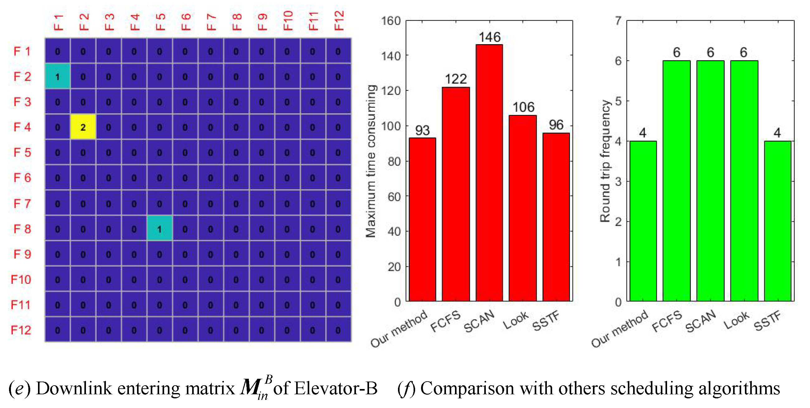
3.2.2. Comparison of Example 2 with Other Four Scheduling Algorithms

In order to compare the effectiveness of the algorithms proposed in Example 2, we have selected four representative traditional scheduling algorithms to compare with our method. The pre-processing also considers the waiting time of all passengers with a time limit, which can quickly obtain qualified users. The matrix iterative optimization algorithm is compared with FCFS, SCAN, LOOK, and SSTF scheduling algorithms. The variables for comparison are the total time of work and full total round-trip frequency are used to evaluate the quality of an algorithm.
(1)
FCFS algorithm
The FCFS does not optimize the search for floors and has no real-time characteristics. It is scheduled according to the order of passenger requests. The advantages of this algorithm are fairness and simplicity, and defects include that the performance of this algorithm will be severely degraded in the case of a large load. In the first cycle, the first two tasks (4,8,2,8) and (10,7,1,9) need to be finished, and then the remaining tasks are completed based on the load limit. If the dual-control elevator adopts the FCFS algorithm, the total time required is T f c f s = 122 s , and the movement frequency is f f c f s = 6 .
(2)
SCAN algorithm
Scanning algorithm (SCAN) is a scheduling algorithm that serves in the order of floors. It allows elevators to continuously run back and forth between the bottom and top floors. This algorithm has high stability, but the disadvantage is that the elevator belongs to the default mode in the same direction every time it runs, which can easily cause the user to choose the wrong direction. Moreover, the average response time of the scanning algorithm is relatively longer. If the dual-control elevator adopts the SCAN algorithm, the total time required is T SCAN = 146 s , and the movement frequency is f SCAN = 6 . This algorithm does not make any optimization in terms of floor response, so the movement time is relatively long.
(3)
LOOK algorithm
This algorithm is similar to the SCAN algorithm and has the characteristics of a round-trip movement. The difference is that the SCAN algorithm has no request at both ends when there is no need to go to the top and bottom of the elevator with no load, especially during off-peak periods, the SCAN algorithm is more energy-efficient, and the running time and elevator utilization are relatively ideal. The maximum time consumption of using the LOOK algorithm is T look = max T 1 , T 2 , T 3 = max ( 26 , 106 , 28 ) = 106 s , and the total frequency of elevator movement is f look = 6 . The LOOK algorithm takes less time, but the frequency of exercise is still relatively high. It is not good enough to balance the floor optimization and waiting time.
(4)
SSTF algorithm
SSTF algorithm, which focuses on the optimization of the elevator to find the floor. The principle of the shortest seeking floor time priority algorithm to select the next service object is the shortest time to find the floor. The advantage is that the request from the nearest floor in the requested queue is the next service object. The drawback is that the algorithm has a short average response time during peak usage periods, but the response variance is large, and the request task of the remote floor has been in a waiting state. The maximum time consumption of using this algorithm is T s s t f = max T 1 , T 2 = max ( 96 , 56 ) = 96 s , and the total frequency of elevator movement is f s s t f = 4 . Compared with the matrix iteration method in this paper, the maximum time consumption and the number of movement frequency are basically the same.

3.2.3. Visualization of Numerical Results

In Figure 7a,c, the capacity matrix C visualization of elevator manned space during Elevator-A upward and downward movement. It needs to be emphasized that the last element and the first element of the capacity matrix C must be equal to the P load max because the elevators on the start floor and the destination floor are empty. As for Figure 7b, it is an uplink entering matrix M i n u p of Elevator-A, which indicates that these users who have been screened by the maximum load of the elevator and the time limit, M i n u p and M o u t u p are generated by the waiting matrix W . Figure 7d is a downlink waiting matrix W down of Elevator-A, and the size and density of reservation people determine whether it is necessary to start Elevator-B. Figure 7e mainly shows the remaining task will be finished by Elevator-B in downlink. Figure 7f uses different algorithms for scheduling for the same set of data. The numerical results show that the method proposed in this paper has the lowest running time and round trip frequency frequency, as well as high efficiency, so the matrix iterative optimization algorithm is better. There are two optimization steps when assigning tasks, namely, the Elevator-AB staying position and the alternate completion of the remaining tasks. This operation is for the balanced assignment of tasks. The operating efficiency of the dual-control elevator in the Example 2 is definitely higher than that of the single elevator in the Example 1. However, the solution theory and the iterative process are similar. The first example is characterized by high floors and strong regularity in the number of reservations. The Example 2 is a 12-story building, but the reservation datas are very close to in real life. Next, in Example 3, we will introduce a 60-story building with 6 elevators to complete the reservation task. Actually, the higher the upper floor and the greater the density of using user’s are, the more advantages of the stability and high efficiency of the algorithm will be reflected in this paper.

3.3. Numerical Example 3

3.3.1. Statement of Issues

This elevator group consists of six Elevator-ABCDEF; they work in coordination with each other. This example simulates a 60-story building where users randomly booking elevators [43,44,45]. There will be a waste of power and too long of a waiting time for users at both ends floor when the operating cycle of all elevators are set 1st to 60th floors. Here, we adopt the hierarchical management model to finish scheduling tasks in order to improve efficiency. Elevator-AB is responsible for the transportation tasks of low floor areas (1st to 20th floors). Elevator-CD is responsible for the middle floor area (Uplink interval: 21st to 40th floors; Downlink interval: 40th to 1st floors). Similarly, Elevator-EF is responsible for high floor areas (Uplink interval: 41st to 60th floors; Downlink interval: 60th to 1st floors). According to the reservation time screening, the qualified data are differential stored in the reservation Task 1 to Task 6.

3.3.2. Numerical Scheduling Results of Elevator Group with 6 Elevators

(1)
Low-rise area.
For super high buildings, we adopt a hierarchical management modle to complete the tasks of the elevator group. The low-floor area refers to floors 1–20, and the booked tasks of users are mainly completed by Elevator-AB. Firstly, the task table needs to be divided into uplink and downlink by the users’ direction demand index value of k. The low-floor reservation information table (tasks to be completed) includes the waiting matrix W down A 1 and W u p A 1 from uplink Task1 and downlink Task2. i represents the initial floor, j is the destination floor, k represents the move direction index in matrix W i j k A 1 , and the subscript of A 1 represents the first motion cycle. W u p A 1 and W down A 1 are all sparse matrix. The up and down tasks of Elevator-AB are shown in Table 3.
The number of starting elevators shall be determined by the flow of people. In this example, we collected reservation data within 2 min at the peak period. The elevator limited load requirements P loadmax = 15 . The time required for the elevator to stay on the reserved floor is t 1 = 4 s , it takes time t 2 = 1 s for the elevator to pass through an unreserved floor. The reference standard for user’s waiting time are: T u p = F b t 1 + F i F min t 2 + t 3 , T down = F b t 1 + F max F i t 2 + t 3 . t 3 indicates the time from the user submission place to walk to the elevator waiting area. In this example, t 3 is 0 s by default, indicating that all users have reached the waiting area. The elevator group system first assigns tasks to Elevator-A; if there are remaining tasks, Elevator-B will complete them. So, the elevator group system allows parts of the users to take the elevator first, and the remaining customers will be take it next time. The move matrix M u p A 1 and M down A 1 are formed from W u p A 1 and W down A 1 . Elevator-A moves upward with a total of 27 people, and Elevator-B moves downward with a total of 40 people. The internal elements of the moving matrix M of Elevator-AB in the first movement cycle up and down are shown in Table 4.
After the system tasks are divided, Elevator-AB actually starts at the same time. It should be emphasized that the initial position of Elevator-A stays on the 1st floor, and Elevator-B stays on the 20th floor. Afterwards, Elevator-A moves upward and Elevator-B moves downward. This belongs to initial location optimization, this setting can quickly respond to users with different destination needs. At the same time, the remaining tasks of Elevator-A and Elevator-B are completed by the other party after they are exchanged. The purpose is to balance the workload of Elevator-AB basically the same and improve the work cooperation efficiency. Following the matrix iterative formula, the uplink remaining tasks of Elevator-A will be completed by Elevator-B. Meanwhile, the downlink remaining tasks of Elevator-B will be completed by Elevator-A; this task assignment satisfies the expression W u p B k = R u p A k , W down A k = R down B k . The first movement cycle tasks of Elevator-AB are shown in Table 5 and Table 6. According to the tasks assigned by the elevator group system, there will be no task transportation errors with each other. In a complete movement cycle (one cycle up and down), the equilibrium efficiencies of Elevator-AB for carrying users is η P = 82.5 % . The specific remaining tasks of Elevator-AB are as follows in Table 5.
(2)
Middle floor area
In the middle floor area, the elevator in the upward movement of the floor reservation interval is from 21st to 40th floor, and downward movement of the floor reservation interval is 40th to 1st floor. Therefore, the user is on the first floor, and the lowest reservation floor is 21 floors; 2–20 floors are prohibited uplink reservations. The advantage of this regulation is to prevent the elevator from running for too long without load, resulting in waste of power supply. In addition, without zoning, it is difficult to ensure that users on high floors can get a timely response. The scheduling tasks are completed by Elevator-CD. The booking data of the middle floor part are shown in Table 6.
The initial position of Elevator-C stays at 1st floor, and the initial position of Elevator-D is the 40th floor. Therefore, in the first iteration, Elevator-C moves upward and Elevator-D moves downward. Firstly, the up and down reservation information are separated according to the value k of director index matrix, and the classified data are stored in the downlink Task 3 and the uplink Task 4, respectively, in Table 6, Task3 and Task4 can be recorded as waiting matrix W down D 1 and W u p C 1 . Task3 and Task4 have the same number of reserved orders, but the total number of reserved orders is significantly different. There are two optimization strategies in the task assignment; one is to optimize the initial parking position, and the other is the cross exchange of up and down tasks, in order to improve the balance of carrying people.
For the task assignment problem in the middle floor, in first half cycle of motion, Elevator-C is responsible for the uplink task, and Elevator-D is responsible for the downlink task. The task assignment principle of Elevator-CD is similar to that of Elevator-AB, only controlling the destination floor range difference from 21st to 40th floor when the elevator moves upward. Elevator-C moves upwards and can carry the total number of 31 people, and Elevator-D moves downwards and takes a total number of 19 people. From Table 7, we can also find that the lowest floor reserved by the user is the 22nd floor, and the highest floor is the 40th floor. In the downlink reservation data, the lowest floor number of the destination is the 1st floor, and the highest floor is the 40th floor. The tasks assigned by the elevator group to the point Elevator-CD can be represented by the moving matrix M u p C 1 and M down D 1 , for which elements are shown in the following, Table 7.
In the second half cycle of the first movement, Elevator-CD will be exchanged with the remaining tasks of the other party’s previous transportation (Table 7) as the transportation task of this time (Table 8), and the transportation direction is also opposite to that of the last time. We can use equation relations W u p D k = R u p C k and W down C k = R down D k to represent the task exchange process. It is also easy to observe the synergy of Elevator-CD from the task table. The task volume of the two is basically the same, which can also shorten the total operation time of elevator group. When the tasks in Table 8 are completed, it indicates that the reservation task in the floor area in the elevator has been completed. After running the scheduling tasks in Table 7 and Table 8, it is equivalent to finishing a complete cycle. Elevator-C carries 13 people in total, and Elevator-D carries 11 people in total. The task balance rate is η P = 81.08 % . The remaining dispatching tasks of elevator CD are shown in the Table 8 below.
(3)
High-rise area
As for the high-rise area, the high floor range is from the 41st to 60th floors, which is mainly completed by Elevator-EF. The initial position of Elevator-E stays at the 41st floor, and the initial position of Elevator-F stays at the 60th floor. Firstly, the uplink and downlink reservation information are divided by the index value of k. The lowest reservation floor number for passengers is 41, and the highest reservation floor number is 60. When the high-floor elevator passes through the 2–40 floors, it runs very fast because those floors are prohibited uplink reservations. Floors 41–60 are the normal working stage, and the speed remains stable. The users who need to go upstairs and downstairs are random, and the total number of requests is the same. The high floor reservation data is as follows Table 9.
We can get the solution of Elevator-EF by the matrix iterative optimization algorithm. The data in Table 9 are transformed into the waiting matrix W down E 1 and W u p E 1 . Due to the limited space of the elevator, it can carry up to 15 people at a time. Therefore, it is impossible for the elevator EF to carry all tasks in a single movement, and the remaining tasks are operated by another elevator. Combining load limit and time constraints to select some users taking the elevator, matrix M u p E 1 and M down F 1 of Elevator-EF can be obtained. The total number of 22 people are carried by Elevator-E when Elevator-E move upward. During the whole process of Elevator-F descending, the total number of 17 passengers are carried by Elevator-F, the results of Elevator-EF carrying task are shown in Table 10.
It is impossible to complete all high floor reservation tasks by relying solely on elevator E, which requires coordination between elevator F. First, when elevator E is started, it is found that there are still remaining tasks R E that are not completed, and the remaining tasks are left to F to complete. Therefore, elevator F is also needed to assist in completing the remaining tasks of elevator E and satisfy the relations W u p F 1 = R u p E 1 , W down E 1 = R down F 1 . Then, we combined the matrix iterative algorithm of this article to finish the remaining tasks, and a complete task of F elevator is as follows, in Table 11. By calculating the number of people carried by elevator EF, the equilibrium rate is 83.64 % . The total 6 elevators are divided into 3 groups according to the floor range. According to the number equilibrium efficiency formula proposed in this paper, we calculate that the overall equilibrium efficiency of the Example 3 elevator group is η P = 82.41 % .

4. Discussion

In this paper, we mainly study the optimization algorithm for group control elevator with reservation function. In terms of data collection, reservations can get accurate data in advance [46]. The difference from traditional elevators is that the reservation elevator’s data is more accurate and complete, such as the number of reservations on each floor, the remaining space of the elevator, and the arrival time; these variables are also key factors in the optimization problem. This paper also proposes the nearest neighbor principle with time constraints, which can quickly select users who meet the standards. Finally, the numerical results can be obtained through the matrix iterative algorithm. In terms of model solving, this paper proposes a matrix iteration method, which can quickly calculate the number of people on each floor, waiting matrix, and remaining matrix. Moreover, the matrix iteration method is more intuitive and concise than the traditional energy method, the Monte Carlo, and the fuzzy control method. For extra-high floors, this article recommends adopting a hierarchical management model. This method improves the speed and utilization of elevators.
In addition, the complexity of the presented algorithms in both the single and group elevator cases will be discussed here. In fact, this is a knowledge connection bridge and focus of application that deserve to be explained. The difference between a single elevator and an elevator group is mainly described from the following points.
(1)
The main characteristics of a single elevator are low floors, low density of people flow, low efficiencies, and relatively simple task management, while the main characteristics of elevator groups are: high floors, high density of people flow, high work efficiency, and synergy between elevators.
(2)
Single elevator task distribution belongs to a one-to-one relationship, and elevator group task assignment belongs to a one-to-many relationship.
(3)
For the same task, the complexity of a single elevator and an elevator group is obviously different. A single elevator needs to consider the total number of reservations p, the total number of floor destinations k, and the round-trip cycle is T = n . p i means to reach the i-th destination floor how many people are going out, and the complex formula of a single elevator is:
O ( n ) = n i = 1 k p p i , i = 1 , 2 , , k .
For the elevator group, the influencing factors of the complexity are the total number of people p, the total number of floor destinations k, the round-trip period of each elevator is T i = n i , and the number of elevators m. Then, the complexity formula of the elevator group is:
O ( m ) = i = 1 M m i · j = 1 N n j t = 1 k p p t , i = 1 , 2 , , M , j = 1 , 2 , , N , t = 1 , 2 , , k .
The complexity of the elevator group is positively correlated with the number of tasks. When there are few tasks, only part of the elevators participate in transportation. When only one elevator starts, the corresponding relationship satisfies F n i = i = 1 M m i = 1 , and the cycle of round trip is T n i = j = 1 N n j = n . At this time, the elevator group has the minimum complexity O min ( n ) , which is the same as the complexity of a single elevator operation, and is denoted as O min ( m ) = O ( n ) . When there are many tasks, each elevator participates in operation, and the operation cycle reaches the maximum of n. Then, the elevator group has the maximum complexity O max ( m ) .
O max ( m ) = m · n · i = 1 k p p i = m O n , i = 1 , 2 , , k .
Therefore, the complexity of the elevator group is a range. The lower limit is a single elevator, and the upper limit is close to m times of the single elevator. Since there is a collaborative optimization in the elevator group, the total number of operation cycles T < m n . The final complexity relationship can be expressed as:
O ( n ) O ( m ) < m O ( n ) .
Furthermore, the advantages of the reservation elevator matrix iteration algorithm are high coordination, fast response, batch process, and adaptive function. Adding face recognition technology to the system can also improve the stability of the algorithm. The deficiency of this model is that our algorithm considers task batch distribution at both ends of the booking floor and does not consider the second point-by-point optimization [47,48]. When the number of reservations increases sharply, the difficulty of optimization and the amount of calculation are increased. In fact, with dynamic redistribution of elevator tasks, there is still room for optimization and improvement. If the second point-by-point optimization is opened, the utilization rate of the elevator will be higher, but the elevator should feedback the position, available space, and unfinished tasks in time whenever it passes through each floor; these tasks will also increase the amount of calculation. The schematic diagram of the two optimization cycles is shown in Figure 8.
Overall, future elevator design should consider creativity and efficiency, to design faster and more convenient commercial buildings, such as the Rubik’s Cube Building, i.e., horizontal elevators and vertical elevators mixed-use so that people can reach any location with a high speed in the building, forming a fast channel, which can help people save a lot of time. Another idea for the development of energy-saving elevators is to use the energy generated by gravitational potential energy to recycle [49]. In addition, shopping malls with a particularly dense flow of people can design double-layer hoisting boxes to increase the number of people and increase the utilization rate [50,51]. For the design of elevator doors, we hope to open three sides, providing people in different directions to quickly enter into the elevator, increasing space utilization. In the densely populated areas of comprehensive buildings, we establish a common spindle elevator in the ring center to save more space and energy. If mobile phone software is embedded with voice recognition, using the reservation system will be more convenient. The reservation model established in this paper can form a foundation for high-speed elevators and high-efficiency modern elevators. The follow-up work will continue to explore and create new algorithms to promote the intelligent building and the digital age realization earlier, as well as better serve the public life of humanity.

5. Conlusions

This article mainly studied the optimization problem of elevator group and advocates the production and use of booking elevators. We have clarified the difference between the reservation elevator and the traditional elevator. A dynamic matrix iterative optimization algorithm is proposed in this article. The indoor navigation UWB algorithm is applied to the reservation system to facilitate people finding the elevator quickly. In addition, we define a new time screening principle, which can quickly select qualified users, accelerate the smooth operation of the elevator, reduce the waiting time of users, and improve the accuracy of task pre-allocation. Three numerical examples are given: a single elevator, double control elevator, and elevator group consisting of 6 elevators. Example 1 is a single elevator in an n-storey building, and the numerical results show that the matrix iteration method to deal with the reservation elevator data is not only very visual, convenient, nor having strong regularity. Example 2, our algorithm, highlights the characteristics of short time and low round-trip frequency by comparing with FCFS, SCAN, LOOK, and SSTF scheduling algorithms. The matrix of numerical iteration is visualized, and the number of people, elevator space, and remaining tasks on each floor can be observed. Example 3, for high-rise buildings, in this paper adopts high, medium, and low hierarchical management model. This model has high coordination, fast response, batch process, and adaptive function. Finally, we also discussed and compared the complexity of single elevator and elevator group algorithms, satisfying the relationship is O ( n ) O ( m ) < m O ( n ) . The advantages and disadvantages of our algorithm are also analyzed in detail, and the research value and significance of this article are further reflected. In the future, we will continue to explore more efficient and intelligent algorithms for elevator groups.

Author Contributions

Conceptualization, W.C. and B.Z.; investigation, B.Z., J.L., L.L. and X.R.; writing–original draft preparation, W.C.; writing–review and editing, W.C.; visualization, W.C., B.Z., L.L. and X.R.; supervision, B.Z., L.L., X.R. and J.L.; funding acquisition, W.C. All authors have read and agreed to the published version of the manuscript.

Funding

This work is supported by Young Science Foundation CN (No. 11701433).

Institutional Review Board Statement

The study was conducted according to the guidelines of the Declaration of Helsinki, ethical review and approval were waived for this study, due to this research purpose is to serve humanity, make our life more convenient and efficient and save electric energy. Numerical solution processes are digital simulation and don’t involve any unethical behavior.

Informed Consent Statement

Informed consent was obtained from all subjects involved in the study.

Data Availability Statement

Data available in a publicly accessible repository.

Acknowledgments

Thanks to anonymous reviewers for their professional advices and valuable suggestions!

Conflicts of Interest

The authors declare that they have no known competing financial interests or personal relationships that could have appeared to influence the work reported in this paper.

References

  1. Cortés, P.; Muñuzuri, J.; Vázquez-Ledesma, A.; Onieva, L. Double deck elevator group control systems using evolutionary algorithms: Interfloor and lunchpeak traffic analysis. Comput. Ind. Eng. 2021, 155, 107190. [Google Scholar] [CrossRef]
  2. D’Ariano, A.; Pacciarelli, D.; Pranzo, M. A branch and bound algorithm for scheduling trains in a railway network. Eur. J. Oper. Res. 2007, 183, 2643–2657. [Google Scholar] [CrossRef]
  3. Hsieh, M.Y.; Ding, J.W. Dynamic scheduling with energy-efficient transmissions in hierarchical wireless sensor networks. Telecommun. Syst. Model. Anal. Des. Manag. 2015, 60, 95–105. [Google Scholar] [CrossRef]
  4. Gardner, K.; Righter, R. Product Forms for FCFS Queueing Models with Arbitrary Server-Job Compatibilities: An Overview. Queueing Syst. 2020, 96, 3–51. [Google Scholar] [CrossRef]
  5. Nail, A.; Caglar, T.; Mark, G.; Faith, E. Disk scheduling with shortest cumulative access time first algorithms. Urkish J. Electr. Eng. Comput. Sci. 2017, 25, 3367–3380. [Google Scholar]
  6. Lee, M.; Kim, K.; Park, C. Real-Time Disk Scheduling Algorithms Based on the Two-Way SCAN Technique. In Proceedings of the 2009 International Conference on Scalable Computing and Communications, Eighth International Conference on Embedded Computing, Dalian, China, 25–27 September 2009; IEEE Computer Society Press: Los Alamitos, CA, USA, 2009; pp. 137–142. [Google Scholar]
  7. Chen, T.S.; Yang, W.P.; Lee, R.C.T. Amortized analysis of some disk scheduling algorithms: SSTF, SCAN, and N-StepSCAN. BIT Numer. Math. 1992, 32, 546–558. [Google Scholar] [CrossRef]
  8. Ding, B.; Zhang, Y.-M.; Peng, X.-Y.; Li, Q.-C.; Tang, H.-Y. A hybrid approach for the analysis and prediction of elevator passenger flow in an office building. Autom. Constr. 2013, 35, 69–78. [Google Scholar] [CrossRef]
  9. Wang, S.; Gong, X.; Song, M.; Fei, C.Y.; Quaadgras, S.; Peng, J.; Zou, P.; Chen, J.; Zhang, W.; Jiao, R.J. Smart dispatching and optimal elevator group control through real-time occupancy-aware deep learning of usage patterns. Adv. Eng. Inform. 2021, 48, 101286. [Google Scholar] [CrossRef]
  10. Nagatani, T. Complex motion of elevators in piecewise map model combined with circle map. Phys. Lett. A 2013, 377, 34–36. [Google Scholar] [CrossRef]
  11. So, A.; Al-Sharif, L. Calculation of the elevator round-trip time under destination group control using offline batch allocations and real-time allocations. J. Build. Eng. 2019, 22, 549–561. [Google Scholar] [CrossRef]
  12. So, A.; Al-Sharif, L.; Chan, W.L. Analytical Round-Trip Time Estimation of a Three-Dimensional Elevator System Based on Exact Stopping Position Identification. J. Build. Eng. 2020, 31, 101390. [Google Scholar] [CrossRef]
  13. Zubair, M.U.; Zhang, X. Explicit data-driven prediction model of annual energy consumed by elevators in residential buildings. J. Build. Eng. 2020, 31, 101278. [Google Scholar] [CrossRef]
  14. Blázquez-García, A.; Conde, A.; Milo, A.; Sánchez, R.; Barrio, I. Short-term office building elevator energy consumption forecast using SARIMA. J. Build. Perform. Simul. 2020, 13, 69–78. [Google Scholar] [CrossRef]
  15. Tukia, T.; Uimonen, S.; Siikonen, M.-L.; Donghi, C.; Lehtonen, M. High-resolution modeling of elevator power consumption. J. Build. Eng. 2018, 18, 210–219. [Google Scholar] [CrossRef] [Green Version]
  16. Zhang, J.; Zong, Q. Energy-saving scheduling optimization under up-peak traffic for group elevator system in building. J. Build. Eng. 2013, 66, 495–504. [Google Scholar] [CrossRef]
  17. Munoz, D.M.; Llanos, C.H.; Ayala-Rincon, M.; van Els, R.H. Distributed approach to group control of elevator systems using fuzzy logic and FPGA implementation of dispatching algorithms. Eng. Appl. Artif. Intell. 2008, 21, 1309–1320. [Google Scholar] [CrossRef]
  18. Jamaludin, J.; Rahim, N.A.; Hew, W.P. Development of a self-tuning fuzzy logic controller for intelligent control of elevator systems. Eng. Appl. Artif. Intell. 2009, 22, 1167–1178. [Google Scholar] [CrossRef]
  19. Zhu, D.; Qian, H.; Zhang, T.; Shan, G.; Wu, L. The Fuzzy Logic Inference Decision System of Elevator Group Supervisory Control. IFAC Proc. Vol. 1998, 31, 117–120. [Google Scholar]
  20. Bolat, B.; Altun, O.; Cortés, P. A particle swarm optimization algorithm for optimal car-call allocation in elevator group control systems. Appl. Soft Comput. 2013, 31, 2633–2642. [Google Scholar] [CrossRef]
  21. Tartan, E.O.; Ciftlikli, C. A Genetic Algorithm Based Elevator Dispatching Method For Waiting Time Optimization. IFAC Pap. OnLine 2016, 49, 424–429. [Google Scholar] [CrossRef]
  22. Cortés, P.; Larrañeta, J.; Onieva, L. Genetic algorithm for controllers in elevator groups: Analysis and simulation during lunchpeak traffic. Appl. Soft Comput. 2004, 4, 159–174. [Google Scholar] [CrossRef]
  23. Bolat, B.; Cortés, P. Genetic and tabu search approaches for optimizing the hall call—Car allocation problem in elevator group systems. Appl. Soft Comput. 2011, 11, 1792–1800. [Google Scholar] [CrossRef]
  24. Chen, J.; Huang, G.Q.; Wang, J.-Q.; Yang, C. A cooperative approach to service booking and scheduling in cloud manufacturing. J. Oper. Res. 2019, 273, 861–873. [Google Scholar] [CrossRef]
  25. Dai, J.; Geng, N.; Xie, X. Dynamic advance scheduling of outpatient appointments in a moving booking window, European. J. Oper. Res. 2021, 292, 622–632. [Google Scholar] [CrossRef]
  26. Sun, Y.; Jiang, Z.; Gu, J.; Zhou, M.; Li, Y.; Zhang, L. Analyzing high speed rail passengers’ train choices based on new online booking data in China. Transp. Res. Part C Emerg. Technol. 2018, 97, 96–113. [Google Scholar] [CrossRef]
  27. Zhao, N.; Luo, L.; Zhang, S.; Lodewijks, G. An efficient simulation model for rack design in multi-elevator shuttle-based storage and retrieval system. Simul. Model. Pract. Theory 2016, 67, 100–116. [Google Scholar]
  28. Ahmadi, A.; Jokar, M.R. An efficient multiple-stage mathematical programming method for advanced single and multi-floor facility layout problems. Appl. Math. Model. 2016, 40, 5605–5620. [Google Scholar] [CrossRef]
  29. Chandakas, E. On demand forecasting of demand-responsive paratransit services with prior reservations. Transp. Res. Part C Emerg. Technol. 2020, 120, 102817. [Google Scholar] [CrossRef]
  30. Bharadwaj, R.; Koul, S.K. Study of the influence of human subject on the indoor channel using compact UWB directive/omni-directional antennas for wireless sensor network applications. Ad Hoc Netw. 2021, 118, 102521. [Google Scholar] [CrossRef]
  31. Waqar, A.; Ahmad, I.; Habibi, D.; Phung, Q.V. Analysis of GPS and UWB positioning system for athlete tracking. Meas. Sens. 2021, 14, 100036. [Google Scholar] [CrossRef]
  32. Zhou, Z.; Rui, Y.; Cai, X.; Lu, J. Constrained total least squares method using TDOA measurements for jointly estimating acoustic emission source and wave velocity. Measurement 2021, 182, 109758. [Google Scholar] [CrossRef]
  33. Friese, P.; Rambau, J. Online-optimization of multi-elevator transport systems with reoptimization algorithms based on set-partitioning models. Discret. Appl. Math. 2006, 154, 1908–1931. [Google Scholar] [CrossRef] [Green Version]
  34. Zhou, B.; Chu, D.; Saak, J.; Xiao, M. Matrix equations with application to control theory. J. Frankl. Inst. 2016, 353, 971–973. [Google Scholar] [CrossRef]
  35. Zhang, D.; Wu, X. Robust and discrete matrix factorization hashing for cross-modal retrieval. Pattern Recognit. 2022, 122, 108343. [Google Scholar] [CrossRef]
  36. Dai, Y.; Li, Y.; Sun, B.; Liu, L.J. Skip-connected network with gram matrix for product image retrieval. Neurocomputing 2021, 447, 307–318. [Google Scholar] [CrossRef]
  37. Brum, A.; Ruiz, R.; Ritt, M. Automatic generation of iterated greedy algorithms for the non-permutation flow shop scheduling problem with total completion time minimization. Comput. Ind. Eng. 2022, 163, 107843. [Google Scholar] [CrossRef]
  38. Tang, H.T.; Chen, R.; Li, Y.B.; Peng, Z.; Guo, S.; Du, Y. Flexible job-shop scheduling with tolerated time interval and limited starting time interval based on hybrid discrete PSO-SA: An application from a casting workshop. Appl. Soft Comput. 2019, 78, 176–194. [Google Scholar] [CrossRef]
  39. Violettas, G.; Simoglou, G.; Petridou, S.; Mamatas, L. A Softwarized Intrusion Detection System for the RPL-based Internet of Things networks. Future Gener. Comput. Syst. 2021, 125, 698–714. [Google Scholar] [CrossRef]
  40. Singh, I.; Kumar, N.; Sharma, S.K.G.T.; Kumar, V.; Singhal, S. Database intrusion detection using role and user behavior based risk assessment. J. Inf. Secur. Appl. 2020, 55, 102654. [Google Scholar] [CrossRef]
  41. Kwon, O.; Lee, E.; Bahn, H. Sensor-aware elevator scheduling for smart building environments. Build. Environ. 2014, 72, 332–342. [Google Scholar] [CrossRef]
  42. Yamauchi, T.; Ide, R.; Sugawara, T. Fair and effective elevator car dispatching method in elevator group control system using cameras. Procedia Comput. Sci. 2019, 159, 455–464. [Google Scholar] [CrossRef]
  43. Debnath, J.K.; Serpen, G. Real-Time Optimal Scheduling of a Group of Elevators in a Multi-Story Robotic Fully-Automated Parking Structure. Procedia Comput. Sci. 2015, 61, 507–514. [Google Scholar] [CrossRef] [Green Version]
  44. Vodopija, A.; Stork, J.; Thomas, B.B.; Filipič, B. Elevator group control as a constrained multiobjective optimization problem. Appl. Soft Comput. 2021, 108277. [Google Scholar] [CrossRef]
  45. Su, X.; Tao, L.; Liu, H.; Wang, L.; Suo, M. Real-time hierarchical risk assessment for UAVs based on recurrent fusion autoencoder and dynamic FCE: A hybrid framework. Appl. Soft Comput. 2021, 106, 107286. [Google Scholar] [CrossRef]
  46. Sun, J.; Zhao, Q.; Luh, P.B. Optimization of Group Elevator Scheduling with Advance Information. IEEE Trans. Autom. Sci. Eng. 2010, 7, 352–363. [Google Scholar] [CrossRef]
  47. Potts, C.N.; Kovalyov, M.Y. Scheduling with batching: A review. Eur. J. Oper. Res. 2000, 120, 228–249. [Google Scholar] [CrossRef]
  48. Blakeley, F.; Argüello, B.; Cao, B.; Hall, W.; Knolmajer, J. Optimizing Periodic Maintenance Operations for Schindler Elevator Corporation. J. Appl. Anal. 2003, 33, 67–79. [Google Scholar] [CrossRef]
  49. Dalala, Z.; Alwahsh, T.; Saadeh, O. Energy recovery control in elevators with automatic rescue application. J. Energy Storag. 2021, 43, 103168. [Google Scholar] [CrossRef]
  50. Tateyama, M.; Tanaka, K. The latest technology of the elevator for ultra-high-speed, large capacity, and ultra-high-rise. Proc. Transp. Logist. Conf. 2013, 22, 27–30. [Google Scholar] [CrossRef]
  51. Sorsa, J. Real-time algorithms for the bilevel double-deck elevator dispatching problem. J. Comput. Optim. 2019, 7, 79–122. [Google Scholar] [CrossRef]
Figure 1. The main interface of reservation elevator APP.
Electronics 10 03179 g001
Figure 2. Interface information of personal information registration.
Electronics 10 03179 g002
Figure 3. Reservation elevator internal data structure relational graph.
Electronics 10 03179 g003
Figure 4. Elevator group internal control and reservation data exchange.
Electronics 10 03179 g004
Figure 5. Multi-sensor data connection and functional of booking elevators.
Electronics 10 03179 g005
Figure 6. Two common ways for users to book elevators.
Electronics 10 03179 g006
Figure 7. Visualization results of double control reservation elevator in Example 2.
Electronics 10 03179 g007aElectronics 10 03179 g007b
Figure 8. Batch optimization and point-to-point optimization work cycle.
Electronics 10 03179 g008
Table 1. All the key variables in models are summarized and explained.
Variable NameExplanation & DescriptionVariable NameExplanation & Description
W Waiting matrix W i j m t i m e The actual total waiting time matrix of users m.
W u p Uplink waiting matrix W u i Uplink waiting index matrix
W d o w n Downlink waiting matrix W d i Downlink waiting index matrix
M Moving matrix M i n Entering matrix
M o u t Exiting matrix R Remaining matrix
C Capacity matrix r i 1 The distance difference between the mobile tag to the i-th base station and the first base station.
t estimate The average time t estimate of users i arrive at elevator j. d i j The distance from the i-th user to the j-th elevator.
T 1 T 1 is a time with elevator move to current i-th layer. T 2 Time T 2 takes for user m from the place of submission to the elevator waiting area.
w i j m t w i j m t = T 1 + T 2 means a actual total waiting time of users. A c ( k ) A c ( k ) When elevator to the k-th floor, the total number of remaining space of elevator.
T i u p The elevator acceptable reference time of up. T i d o w n The elevator acceptable reference time of down.
F b F b contains the reservation starting floor set S and the destination floor set D . δ i j 0 The elevator space judgment functions in the initial state.
δ i j k The elevator space judgment functions at the middle k-th floor. P load max Maximum number of people on elevator load.
η P The equilibrium rate of elevator group in a one cycle is based on the total number of users. η T The equilibrium rate of elevator group in a one cycle is based on the total running time.
O ( n ) The complexity of a single elevator. O ( m ) The complexity of the elevator group.
Table 2. Reservation tasks of 12-story building transported by double Elevator-AB.
Initial floor1111108765432
Time limit44915202530354045
Destination floor10875311211
Task1People Number9697811786
Down (k)1111111111
Initial floor34567910
Time limit6111621263237
Destination floor5889111111
Task2People Number8827211
U p ( k ) 2222222
Note: The bold data is reserved first, and other dates are reserved in order.
Table 3. Reservation tasks in the low area transported by Elevator-AB.
Initial floor18161514121097654
Time limit612172232424757626772
Destination floor11311108741211
Task1People Number16735427263
(A-B)Down (k)11111111111
Initial floor145710121415161718
Time limit411162227334550556065
Destination floor58101215192019202020
Task2People Number53242412112
(A-B)Up (k)22222222222
Table 4. Scheduling tasks of Elevator-AB in the first half cycle.
i1457101214151618
j1881012151920192020
M u p A 1 k2222222222
P9213241212
i18161514121097654
j11311108741211
M down B 1 k11111111111
P16715427232
Table 5. Scheduling tasks of Elevator-AB in the second half cycle.
i7141617 i4514
j12202020 j1110
M u p B 1 k2222 M down A 1 k111
P4111 P132
Table 6. Reservation tasks in the middle area transported by Elevator-CD.
Initial floor4038353128262524232220
Time limit410172532384348535864
Destination floor1815221925171412811
Task3People Number15212426432
(C-D)Down (k)11111111111
Initial floor14152022242931333436
Time limit411263541476070768191
Destination floor2228303335353738394040
Task4People Number95251631541
(C-D)Up (k)22222222222
Table 7. Scheduling tasks of Elevator-CD in the first half cycle.
i1415222429313336
j222830353537383940
M u p C 1 k222222222
P951163141
i2225262831353840
j114172519221518
M down D 1 k11111111
P22421251
Table 8. Scheduling tasks of Elevator-CD in the second half cycle.
i15203334 i20222324
j30333940 j11812
M u p D 1 k2222 M down C 1 k1111
P1514 P2146
Table 9. Reservation tasks in high-rise areas transported by Elevator-EF.
Initial floor6058575251504846434040
Time limitred410152429344046536060
Destination floor12423115512
Task5People Number12423115512
(E-F)Down (k)11111111111
Initial floor14151724303239414245
Time limit411263243535970768192
Destination floor4148445245395051596060
Task6People Number22411173116
(E-F)Up (k)22222222222
Table 10. Scheduling tasks of Elevator-EF in the first half cycle.
i1415243032394142
M u p E 1 j41484445395051596060
k2222222222
P2241141115
M down F 1 i605857525150484643
j11931431733343022
k111111111
P124231112
Table 11. Scheduling tasks of Elevator-EF in the second half cycle.
i323945 i46434040
j505160 j3022118
M u p F 1 k222 M down E 1 k1111
P 321 P4321
Publisher’s Note: MDPI stays neutral with regard to jurisdictional claims in published maps and institutional affiliations.

