1. Introduction
Today, renewable energy sources (RESs) are widespread and are becoming more attractive compared with systems based on fossil fuels such as oil, coal and gas [
1]. RESs have some advantages such as harmless emissions into the environment and close location to the consumer. The use of RES technologies leads to saving conventional fossil fuels. RES technologies can be primarily attributed to photovoltaic energy production [
2,
3]. Power electronic systems (PESs) are the key state-of-the-art development in these RES technologies. The most important part of a PES is the power semiconductor converter. Increasing the installed power of a PV power generation system (PVPGS) leads to increased power of the semiconductor converter, which is an integral part of the system [
2,
3,
4,
5,
6,
7,
8,
9,
10]. For these reasons, multilevel semiconductor converters are typically used. A PV power generation system usually has a transformer in its structure for voltage level conversion and galvanic isolation from the grid, but the use of a transformer makes the system less efficient and increases the weight and size parameters. References [
11,
12,
13] include some research papers on transformerless PVPGSs. The elimination of the transformer leads to the following negative phenomena. The main negative phenomenon is the presence of the so-called common-mode leakage current. This current is a flow through the loops made by the parasitic elements (capacitances and inductances) [
14]. The leakage current worsens the power quality and creates emergency situations, for example faults of thin-film PV panels and, as a result, a system failure. It also creates unsafe operating conditions for the personnel [
15].
There are various methods of CMLC suppression: schematic and algorithmic or both. Different types of converters and their modifications can suppress CMLC for schematic methods [
16], and there are various pulse-width modulation (PWM) techniques and predictive control systems for algorithmic methods [
15,
17]. Predictive control systems do not allow the elimination of CLMC in transformerless grid-tied PV-generation systems. Predictive control systems only reduce leakage currents and in some cases deteriorate converter efficiency.
Thus, in [
18], the use of a filtering Cleack capacitor is proposed, which, if L is not taken into account, can lead to voltage resonance and nullify its introduction. A PWM technique also proposed, which can balance the capacitors of the DC link; however, it does not completely suppress the common-mode current but reduces its surges [
19]. There is a technique for suppressing the common-mode leakage current in a multilevel FC converter, which has more disadvantages compared to the NPC, which is proposed in the current work [
20]. Variants with the use of two-level inverters with low efficiency are proposed [
21]. In addition, other works have proposed new topologies of converters [
22].
The authors developed a possible solution to eliminate leakage currents in a single-phase system based on a multilevel power semiconductor converter. A schematic and algorithmic solution was reviewed in [
23,
24].
The paper is organized as follows.
Section 2 gives a brief description of the leakage current in the PVPGS.
Section 3 presents the developed converter for the PVPGS with the reduction of the leakage current.
Section 4 presents the results of experimental research.
2. Leakage Current
The structure of the considered single-phase grid-tied transformerless PVPGS with the considered parasitic capacitances is illustrated in
Figure 1. The elements of the PVPGS are discussed in [
14,
23]. The proposed converter was chosen as the one most characteristic of this problem, the solution of which this study addressed; this is discussed in more detail in
Section 3. The PVPGS consists of several parts. The most important are PV modules and the voltage source converter (VSC).
The voltage source converter has two components of output voltage,
and
—terminals 1 and 2, as shown in
Figure 1.
is differential mode voltage, and
is common-mode voltage. VSC voltage components
and
are the main cause of the CMLC presence. The
component is eliminated by equalizing the parameters of output filter inductances.
Therefore, the
component produces CMLC
. The circuit diagram in
Figure 1 can be simplified as shown in [
23,
24].
The common-mode leakage current in this circuit diagram is found by Kirchhoff’s voltage law as:
where
is the common-mode voltage of the
-th harmonic,
is the angular frequency of the
-th harmonic,
is the frequency of PWM and
is the equivalent parasitic capacitance (EPC) of the PV module. An average value of EPC is estimated as 100 nF per 1 kW of the power of the PV module,
is the parasitic loop impedance,
is the capacitance of the EMC filter relative to the ground line and
is the equivalent reactance of the output inductors.
As can be seen in Equation (1), the common-mode leakage current has a polyharmonic character with different frequency content. It is defined by the spectral composition of the common-mode voltage. It is obvious that the common-mode voltage acquires the character of a constant signal and takes into account the capacitive character of the common-mode leakage current that provide a CMLC value equal to zero. This condition is achieved when the current frequency is equal to zero. The idea of synthesizing a single-phase multilevel semiconductor converter to eliminate the CMLC suppression is presented based on this condition.
Another method of common-mode leakage current suppression is achieved when , i.e., when breaking the leakage loop. This parameter depends on the type of grounding of the circuit, and in some cases it can be neglected. The emergence of this parasitic factor is caused by the PVPGS area, soil specific resistance, etc. It becomes clear that an elegant way to provide PVPGS operation and suppress CMLC is to achieve a zero frequency of .
The magnitude of voltage pulsation is estimated by the expression , where is the DC-link voltage, m is number of phase legs and is the number of voltage levels. The following assumptions are made:
- (a)
The common-mode voltage is calculated as a mean value of all phase to ground inverter voltages.
- (b)
The voltage level of is defined by a voltage step of the multilevel semiconductor VSI, that is .
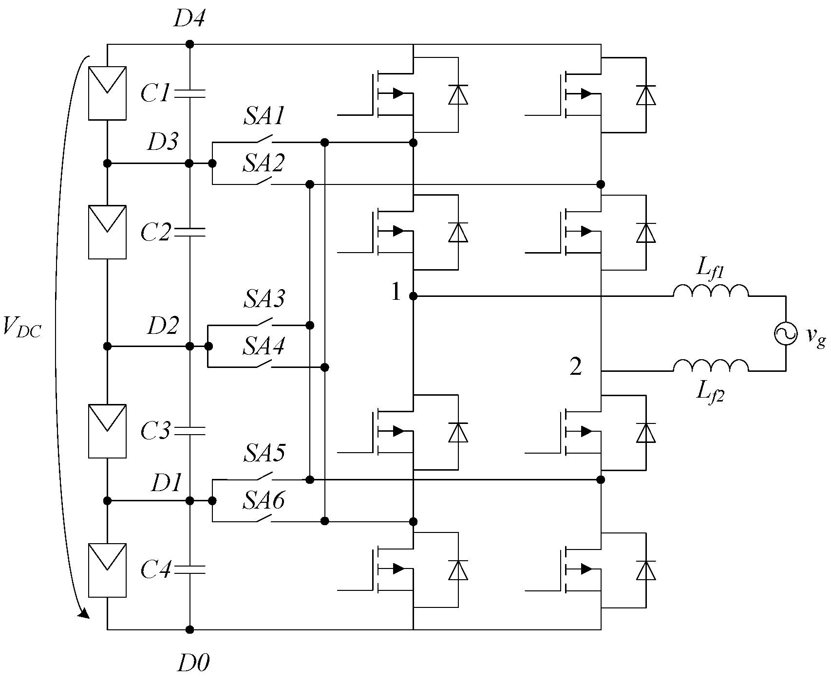
3. A Single-Phase Multilevel Converter with Current Cancelation
Low-power systems (3–5 kW) usually work in single-phase AC grids. Thus, a PVPGS has a single-phase power converter. Currently, a promising direction is the use of multilevel semiconductor converters as part of the PVPGS. These topologies have a number of advantages in comparison with two-level inverters, since they can improve the quality of the generated electrical energy as part of the PVPGS without increasing the PWM frequency. By obtaining a more accurate approximation of the shape of the generated signals, it is possible to achieve a reduction in the weight, size and cost of the filters used. Multilevel converters are often used in different power generation systems. A three-level NPC converter a common type of single-phase multilevel voltage source converter (
Figure 2). Neutral-point clamped (NPC) and flying capacitor (FC) multilevel converters are equivalent to each other in the quality of the generated voltage and current; however, the FC has a larger number of capacitors, which worsens its price performance. From this point of view, it is preferable to use an NPC inverter. In these multilevel VSCs, several types of PWM are usually used, namely space vector (SV) and carrier-based or hysteresis PWM. To reduce the common-mode leakage current, it is possible to use vector PWM as a way to control power converter, as proposed in [
23].
In this topology the differential voltage can take five voltage levels depending on the switching states of the multilevel semiconductor converter: . Common-mode voltage takes the following values: .
In order to eliminate CMLC common-mode voltage must be maintained at any value of
proposed previously. In [
16], a three-level NPC converter operates in a two-level mode.
To work in the level output voltage mode, a level converter is needed.
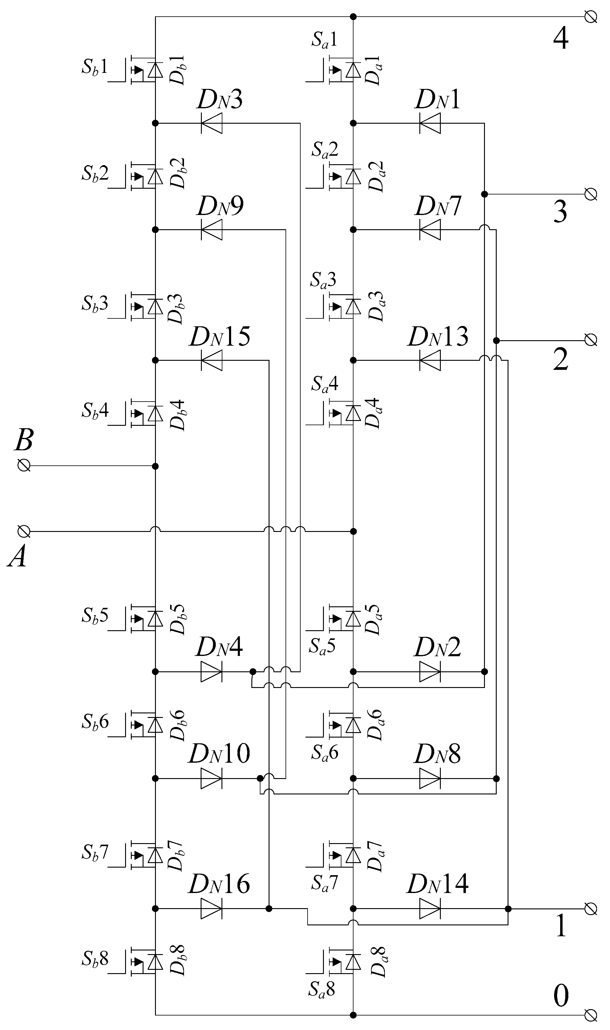
It is clear that a five-level converter is needed for three-level output voltage generation with CLMC suppression. There are two types of NPC converters that allow CLMC suppression and three-level output voltage generation [
23,
24]. The diagram of SV PWM state switching for both converters is shown in
Figure 3. The five-level NPC converter is shown in
Figure 4. A modified five-level NPC converter proposed in [
23] is shown in
Figure 5.
Although the modified NPC converter has a five-level topology, it still operates in the three-level mode to maintain the leakage current suppression.
In the case of the DC-link unbalance, choppers providing the voltage balancing must be implemented.
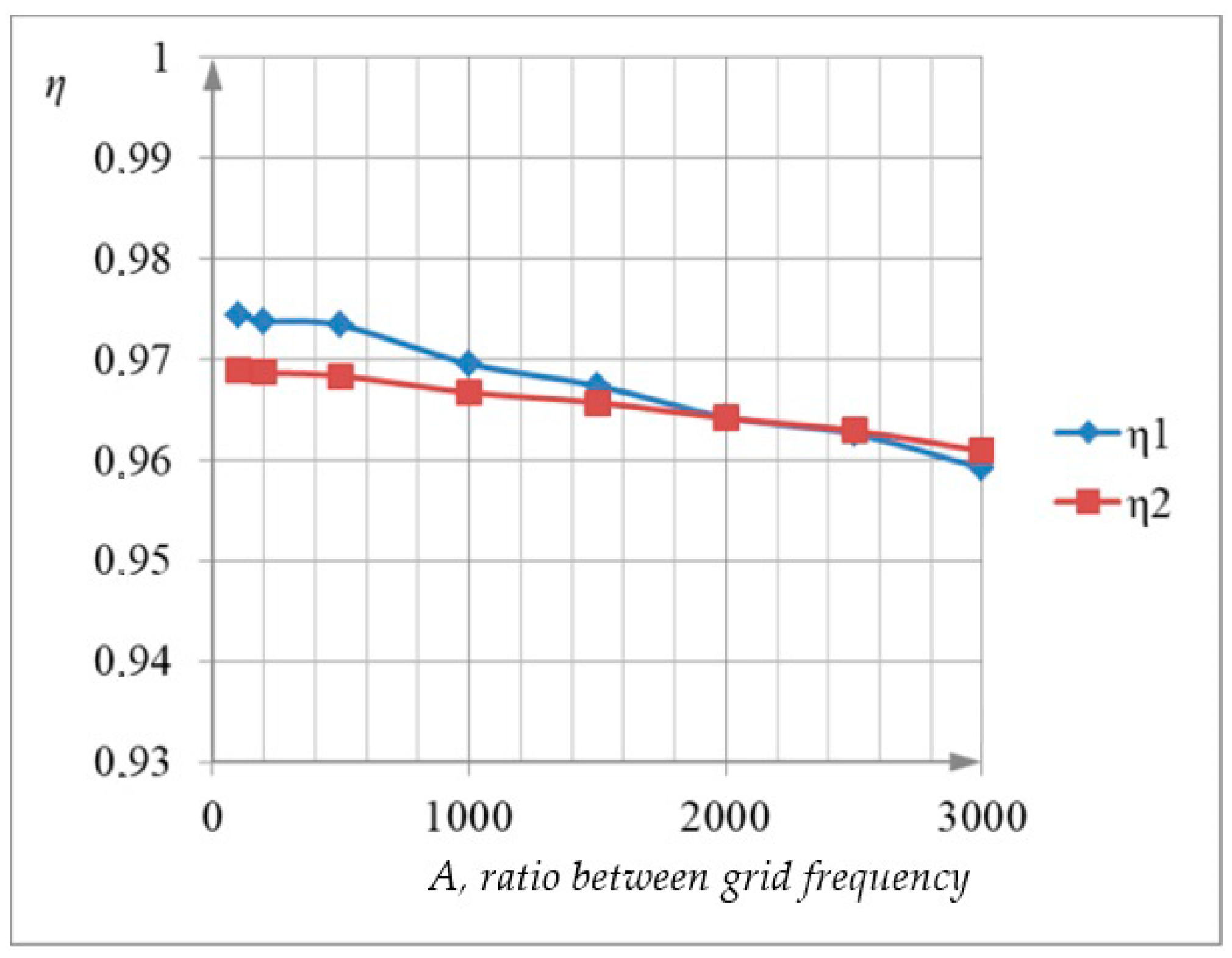
The efficiency of MOSFET transistors and SV PWM of the same switching pattern was calculated as a percentage for both converters. The results of efficiency calculation for the modified single-phase five-level semiconductor converter and for a single-phase five-level semiconductor converter were obtained for them to operate in the CMLC suppression mode (
Figure 6) for different
values.
is the ratio between grid frequency and PWM frequency. As can be seen in
Figure 6, the modified converter has an advantage in efficiency up to
more than 2000.
This is explained by the fact that the modified semiconductor converter has fewer static power losses than the converter (
Figure 6), and dynamic power losses are higher, up to a given frequency multiplicity. Static power losses prevail over dynamic power losses up to the range of 2000. Thus, the range up to the frequency multiplicity is the range of energy-efficient operation of the modified single-phase semiconductor converter.
4. Experiment Results
Figure 7 presents an experimental model of a single-phase PVPGS with the function of reducing the leakage current presented in
Figure 8. The control system was implemented on the Discovery kit with MCU STM32F407VG. A galvanic isolated power system for drive power was made on the International Rectifier IR2153. MOSFET IRF740S was used as power transistors.
The experimental model has the following parameters:
Rated power: 1.2 kW;
DC-link voltage: 400 V;
Filter inductances: Lf1 = 65 uH;
Filter inductances: Lf2 = 72 uH;
PV leakage capacitance: ;
Parasitic loop impedance: ;
Capacitors .
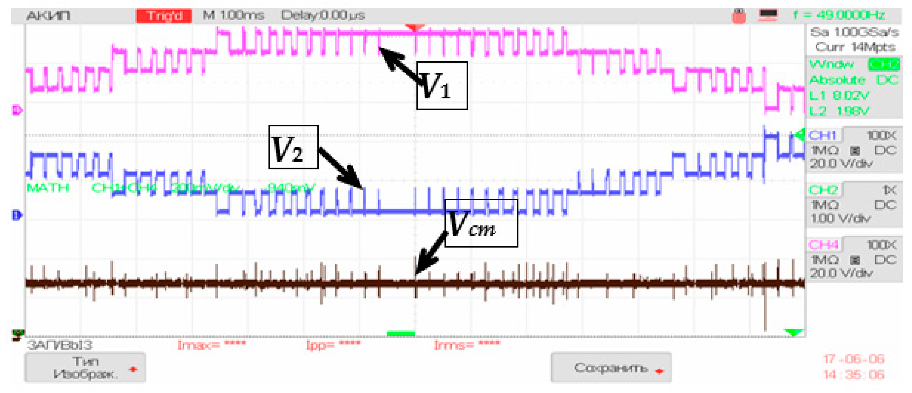
Figure 8 and
Figure 9 represent experimental results of PVPGS operation with the modified converter.
As shown, the main common-mode current source is a common-mode voltage source.
Figure 9 shows the voltage oscillograms of a five-level inverter, where it can be seen that there is an alternating common-mode voltage. As seen from
Figure 8, the common-mode voltage has the character of a constant signal. This was achieved through the use of the proposed converter and control algorithm.
A new topology of a five-level semiconductor converter was synthesized, and a vector pulse-width modulation algorithm to control this converter was proposed. The experimental results confirmed the possibility of forming a common-mode voltage having a character of a constant signal and, consequently, eliminating common-mode leakage current. This in turn gives reasons to believe that the implementation of autonomous power generation systems using the proposed type of the semiconductor converter will improve the functional and operational characteristics of PVPGSs, such as electrical safety and reliability.
5. Conclusions
The structure of the PVPGS, which includes a multilevel semiconductor converter proposed by the authors, as well as the control algorithm was tested. This is the main contribution of the authors. A vector-based PWM strategy to be used in this type of multi-level semiconductor converters was also developed, which allows the formation of the common-mode voltage having the character of a constant signal. In addition, a fundamental possibility of eliminating the transformer from the structure of the generating system while maintaining the quality of the output current and voltage was demonstrated. Experimental research aimed at verifying these results was also carried out. Nevertheless, in this work there were limitations associated with the choice of the converter topologies. Similar algorithms proposed in this work are applicable in more multilevel converters, the scope of which is currently being investigated and will be presented in future works.
Author Contributions
Conceptualization, E.V.G. and S.V.B.; methodology, E.V.G.; validation, A.V.U.; formal analysis, S.V.B.; resources, A.V.U.; writing—original draft preparation, E.V.G. and S.M.S.; writing—review and editing, A.V.U. and S.M.S.; supervision, S.V.B.; project administration, S.V.B. All authors have read and agreed to the published version of the manuscript.
Funding
This research was funded by grant of the Russian Federation President according to the research project No. MK-2204.2020.8.
Institutional Review Board Statement
Not applicable.
Informed Consent Statement
Not applicable.
Data Availability Statement
The data presented in this study are available on request from the corresponding author. The data are not publicly available due to privacy issues.
Conflicts of Interest
The authors declare no conflict of interest.
References
- Calabrese, D.; Tricarico, G.; Brescia, E.; Cascella, G.L.; Monopoli, V.G.; Cupertino, F. Variable Structure Control of a Small Ducted Wind Turbine in the Whole Wind Speed Range Using a Luenberger Observer. Energies 2020, 13, 4647. [Google Scholar] [CrossRef]
- Zhang, L.; Sun, K.; Feng, L.; Wu, H.; Xing, Y. A family of neutral point clamped full-bridge topologies for transformerless pho-tovoltaic grid-tied inverters. IEEE Trans. Power Electron. 2013, 28, 730–739. [Google Scholar] [CrossRef]
- Anandababu, C.; Fernandes, B.G. Improved full-bridge neutral point clamped transformerless inverter for photovoltaic grid-connected system. In Proceedings of the 2013 IECON—39th Annual Conference of the IEEE Industrial Electronics Society, Vienna, Austria, 10–13 November 2013; pp. 7996–8001. [Google Scholar]
- Sotoodeh, P.; Miller, R. A new single-phase inverter with D-STATCOM capability for grid-connected small wind turbines. In Proceedings of the 2013 IEEE—Power and Energy Conference at Illinois (PECI), Urbana, IL, USA, 22–23 February 2013; pp. 175–179. [Google Scholar]
- Lumbreras, C.; Guerrero, J.M.; Garcia, P.; Briz, F.; Diaz, D. Development and testing of a micro-wind generating system. In Proceedings of the 2013 IEEE—International Conference on New Concepts in Smart Cities: Fostering Public and Private Alliances (Smart MILE), Gijon, Spain, 11–13 December 2013; pp. 1–6. [Google Scholar]
- Chen, G.R.; Jou, H.L.; Wu, K.D.; Wu, J.C. Single-phase three-wire fuel-cell generation system for micro-grid. In Proceedings of the 2014 IEEE—9th Conference on Industrial Electronics and Applications (ICIEA), Hangzhou, China, 9–11 June 2014; pp. 610–615. [Google Scholar]
- Wakeham, D.; Fabre, J.; Builder, D.; Earle, M.; Wilson, J. Power from the sea: A plan to develop ocean energy to meet consumer utility needs. In Proceedings of the 2002 IEEE—OCEANS’02 MTS Conference, Biloxi, MI, USA, 29–31 October 2002; pp. 1615–1621. [Google Scholar]
- Fletcher, J.; Judendorfer, T.; Mueller, M.; Hassanain, N.; Muhr, M. Electrical issues associated with sea-water immersed windings in electrical generators for wave-and tidal current-driven power generation. IET Renew. Power Gener. 2009, 3, 254–264. [Google Scholar] [CrossRef]
- Brescia, E.; Palmieri, M.; Cascella, G.L.; Cupertino, F. Optimal Tooth Tips Design for Cogging Torque Suppression of Permanent Magnet Machines with a Segmented Stator Core. In Proceedings of the 2020 IEEE—International Conference on Electrical Machines (ICEM), Gothenburg, Sweden, 23–26 August 2020; pp. 1930–1936. [Google Scholar] [CrossRef]
- Brescia, E.; Costantino, D.; Massenio, P.R.; Monopoli, V.G.; Cupertino, F.; Cascella, G.L. A Design Method for the Cogging Torque Minimization of Permanent Magnet Machines with a Segmented Stator Core Based on ANN Surrogate Models. Energies 2021, 14, 1880. [Google Scholar] [CrossRef]
- Barater, D.; Lorenzani, E.; Concari, C.; Franceschini, G.; Buticchi, G. Recent advances in single-phase transformerless photovoltaic inverters. IET Renew. Power Gener. 2016, 10, 260–273. [Google Scholar] [CrossRef]
- Vazquez, N.; Vazquez, J.; Vaquero, J.; Hernandez, C.; Vazquez, E.; Osorio, R. Integrating Two Stages as a Common-Mode Transformerless Photovoltaic Converter. IEEE Trans. Ind. Electron. 2017, 64, 7498–7507. [Google Scholar] [CrossRef]
- Datta, A.; Bhattacharya, G.; Mukherjee, D.; Saha, H. Ground leakage current elimination in a transformerless unipolar modulation based single phase grid-connected photovoltaic system. In Proceedings of the 2013 IEEE PES—Asia-Pacific Power and Energy Engineering Conference (APPEEC), Hong Kong, China, 8–11 December 2013; pp. 1–5. [Google Scholar]
- Gubia, E.; Sanchis, P.; Ursua, A.; Lopez, J.; Marroyo, L. Ground currents in single-phase transformerless photovoltaic systems. Prog. Photovolt. Res. Appl. 2007, 15, 629–650. [Google Scholar] [CrossRef]
- Farias, A.M.; Oliveira, K.C.; Cavalcanti, M.C.; Neves, F.A.S. Modulation for three-phase transformerless neutral point clamped inverter in photovoltaic systems. In Proceedings of the 2011 IEEE—XI Brazilian Power Electronics Conference, Natal, Brazil, 11–15 September 2011; pp. 850–857. [Google Scholar]
- Karraker, D.W.; Kalyan, P.G.; Matti, T.J. Inverter for Solar Cell Array. U.S. Patent Application No. 13/151,766, 2 June 2011. [Google Scholar]
- Safari, N.; Ansari, O.A.; Chung, C.Y. A predictive direct power control technique for transformerless grid connected PV systems application. In Proceedings of the 2016 IEEE—Electrical Power and Energy Conference (EPEC), Ottawa, ON, Canada, 12–14 October 2016; pp. 1–6. [Google Scholar]
- Wang, H.; Mao, M.; Chang, L. Single-Phase Transformer-less Inverter with Leakage Current Suppression and Active Power Decoupling Capabilities. In Proceedings of the 4th IEEE Workshop on the Electronic Grid (eGRID), Xiamen, China, 11–14 November 2019; pp. 1–6. [Google Scholar]
- Qiu, J.; He, Y.; Xu, L.; Jiao, Q. A Novel SVPWM Technique for Leakage Current Reduction and Neutral-Point Voltage Balance in Transformerless Three-Level Inverters. In Proceedings of the 2020 IEEE¬4th International Conference on HVDC (HVDC), Xi’an, China, 6–9 November 2020; pp. 560–565. [Google Scholar]
- Zhao, X.; Jiang, D.; Chen, J.; Shen, Z.; Li, Q. Leakage Current Suppression with Capacitor Voltage Control of Three-level Flying Capacitor Grid-Connected Inverters. IEEE Trans. Ind. Electron. 2021. [Google Scholar] [CrossRef]
- Akpınar, E.; Balıkcı, A.; Durbaba, E.; Azizoğlu, B.T. Single-phase transformerless photovoltaic inverter with suppressing resonance in improved H6. IEEE Trans. Power Electron. 2018, 34, 8304–8316. [Google Scholar] [CrossRef]
- Zhu, X.; Wang, H.; Sun, R.; Wang, H.; Zhang, W.; Deng, X.; Yue, X. Leakage Current Suppression of Single-Phase Five-Level Inverter for Transformer-less PV System. IEEE Trans. Ind. Electron. 2021, 68, 10422–10435. [Google Scholar] [CrossRef]
- Grishanov, E.V.; Brovanov, S.V.; Dybko, M. A New Grid-Tied Multilevel VSC for PV with Leakage Current Suppression. In Proceedings of the 2015 IEEE EUROCON—International Conference on Computer as a Tool, Salamanca, Spain, 8–11 September 2015; pp. 613–619. [Google Scholar]
- Grishanov, E.V.; Brovanov, S.V. Aspects of common-mode leakage current suppression in single-phase PV-generation systems. In Proceedings of the 2017 IEEE—18th International Conference of Young Specialists on Micro/Nanotechnologies and Electron Devices (EDM), Erlagol, Russia, 29 June–3 July 2017; pp. 541–546. [Google Scholar]
| Publisher’s Note: MDPI stays neutral with regard to jurisdictional claims in published maps and institutional affiliations. |
© 2021 by the authors. Licensee MDPI, Basel, Switzerland. This article is an open access article distributed under the terms and conditions of the Creative Commons Attribution (CC BY) license (https://creativecommons.org/licenses/by/4.0/).


 ,
, 


