Article

Global Optimal Stabilization of MT-HVDC Systems: Inverse Optimal Control Approach

by
Oscar Danilo Montoya
1,2,*,
Walter Gil-González
3,
Federico Martin Serra
4,
Cristian Hernan De Angelo
5 and
Jesus C. Hernández
6,*
1
Facultad de Ingeniería, Universidad Distrital Francisco José de Caldas, Bogotá 110231, Colombia
2
Laboratorio Inteligente de Energía, Universidad Tecnológica de Bolívar, Cartagena 131001, Colombia
3
Facultad de Ingeniería, Institución Universitaria Pascual Bravo, Campus Robledo, Medellín 050036, Colombia
4
Laboratorio de Control Automático (LCA), Facultad de Ingeniería y Ciencias Agropecuarias, Universidad Nacional de San Luis—CONICET, Villa Mercedes, San Luis 5730, Argentina
5
Grupo de Electrónica Aplicada (GEA), Facultad de Ingeniería, Instituto de Investigaciones en Tecnologías Energéticas y Materiales Avanzados (IITEMA)—CONICET, Universidad Nacional de Río Cuarto, Río Cuarto, Córdoba 5800, Argentina
6
Department of Electrical Engineering, University of Jaén, Campus Lagunillas s/n, Edificio A3, 23071 Jaén, Spain
*
Authors to whom correspondence should be addressed.
Electronics 2021, 10(22), 2819; https://doi.org/10.3390/electronics10222819
Submission received: 7 October 2021 / Revised: 15 November 2021 / Accepted: 15 November 2021 / Published: 17 November 2021
(This article belongs to the Special Issue 10th Anniversary of Electronics: Recent Advances in Power Electronics)

Abstract

:
The stabilization problem of multi-terminal high-voltage direct current (MT-HVDC) systems feeding constant power loads is addressed in this paper using an inverse optimal control (IOC). A hierarchical control structure using a convex optimization model in the secondary control stage and the IOC in the primary control stage is proposed to determine the set of references that allows the stabilization of the network under load variations. The main advantage of the IOC is that this control method ensures the closed-loop stability of the whole MT-HVDC system using a control Lyapunov function to determine the optimal control law. Numerical results in a reduced version of the CIGRE MT-HVDC system show the effectiveness of the IOC to stabilize the system under large disturbance scenarios, such as short-circuit events and topology changes. All the simulations are carried out in the MATLAB/Simulink environment.

1. Introduction

1.1. General Context

HVDC systems have gained much attention in recent decades due to the advantage over power transmission capabilities with low power losses instead of HVAC because there is no radiation, induction, and dielectric losses. In addition, the lines of the HVDC systems produce low-intensity noise interference compared to HVAC transmission lines [1]. The HVDC systems allow a friendly integration of renewable energies, guaranteeing their stability and optimal operation [2]. Therefore, they need advanced control and optimization methods to perform their optimal and proper operation. The control of the HVDC systems is carried out by managing the power electronic converter devices related to each energy resource [3,4], while the optimal operation of the HVDC systems is performed to obtain the best operation point [5]. In general, to ensure a satisfactory operation of an electrical network, even with AC or DC technologies, it is mandatory to use different levels of control that are entrusted with the stabilization of the grid and the possibility of recovering the secure operation after large disturbance events; as well as the possibility to maintain the grid in an optimal operation point under steady-state conditions. Each one of these levels of control can be condensed with hierarchical operation strategies divided from tertiary to primary levels [6,7]. The tertiary stage is entrusted with determining the best operative point as a function of the grid operator requirements, i.e., energy losses or voltage profile performance, among other possible objectives [8]. Once the optimal operative point is defined, it is transferred to the primary and secondary control stages where the power electronic converters that interface renewable energy resources, energy storage systems, conventional sources, and constant power loads [9]. The main challenge with the design of the hierarchical controller corresponds to the possibility of ensuring global optimization properties in the tertiary control stage and asymptotic stability in the primary and secondary control layers [10].

1.2. Motivation

The study of HVDC systems represents a significant challenge from the point of view of the hierarchical control design since each one of the control stages must be adequately defined to ensure the secure operation of the network regarding stability and optimality properties [9]. In the tertiary control stage, optimization methodologies are required to ensure that the reference point provided to the primary and secondary control stages are indeed optimal [8]. However, owing to the nonlinear non-convex nature of the optimal power flow problem for HVDC systems [11], this task must be entrusted to convex approximations such as semidefinite programming or second-order cone equivalents of the exact power flow problem that ensure the global optimum reaching. In relation with the primary-secondary control schemes, control methodologies are required that allow reaching the reference points ensuring asymptotically stability properties [12]. However, due to the nonlinear characteristics associated with the grid dynamic model, the control problem requires advanced nonlinear control approaches [13].
Please note that the nonlinearities in the optimization and control stages in the operation and control design of HVDC systems motivate this research to propose a novel hierarchical control strategy that ensures the optimality and stability conditions in closed-loop operation for this type of power system. There are several optimal control approaches that can adapt to this problem such as direct optimal control (DOC) [14], optimal LMI-based state feedback control (OFC-LMI) [15], inverse optimal control (IOC) [16,17], among others. The DOC method performs the optimization considering various limiting constraints, which are transcribed the several-dimensional problem to a finite-dimensional one [14]. The OFC-LMI approach is mainly used in problems with uncertain nonlinear systems, which can be represented as Lipschitz nonlinearities [15]. The IOC method is based on Lyapunov’s control functions, guaranteeing asymptotic stability in nonlinear systems under optimal control law [16,17]. The problem with the first two approaches is that they may require much computation and not take advantage of the system topology to propose a simple control law. In contrast, the IOC method can take advantage of the system topology from the Lyapunov candidate function.

1.3. Review of the State-of-the-Art

Many authors have proposed several control methods and studies for multi-terminal (MT) HVDC systems. In [18], the power transfer capacity on MT-HVDC systems was studied as well as their small-signal analysis of under-damped oscillations in the inter-area modes. In [19], an active power-sharing in large-scale MT-HVDC systems was presented to improve droop-based control and thus, reinforce the stability of the DC systems based on droop parameters. In [20], it was studied and analyzed how the size of the capacitors affects the voltage peaks in MT-HVDC systems under disturbance. Additionally, the impact of the droop resistance under primary control was analyzed using conventional PI controllers. In [21], the optimal operation and stabilization of MT-HVDC systems were proposed via passivity-based control and convex optimization. Other controllers have been proposed, such as the power-sharing controls [22,23], feedback nonlinear control based on the Lyapunov theory [24], predictive fuzzy control model [25], Kalman filter control [26], model predictive control [27]. Unlike previous works, we propose an IOC method to perform the primary control of an MT-HVDC system, which guarantees the whole system’s closed-loop stability by employing a control Lyapunov function to design the optimal control law. At the same time, the secondary control is carried out for a convex optimization model, which determines the optimal operating points.

1.4. Contributions and Scope

Based on the revision of the state-of-the-art, the main contributions of this research are listed below:
The application of a robust control technique named inverse optimal control to MT-HVDC systems that ensures asymptotically stability properties in the sense of Lyapunov for closed-loop operation, and optimality properties with respect to the reference operational point.
The proposition of a new hierarchical-based control design for MT-HVDC systems by combining a semidefinite programming model to solve the optimal power flow problem in the tertiary level and the IOC to ensure the asymptotic convergence of the voltage variables to their references in the primary-secondary control level.
The application of the proposed hierarchical control scheme is focused mainly on transmission systems with meshed structures and a high presence of constant power loads. Nevertheless, the proposed approach is perfectly applicable to low-voltage DC grids with radial or meshed structures without any modification. On the other hand, the main characteristic of the proposed controller is associated with its centralized nature, since all the measures of the state variables in the constant power terminals are required to generate the feedback control law that will be sent to all the power electronic converters that interface these terminals.

1.5. Document Organization
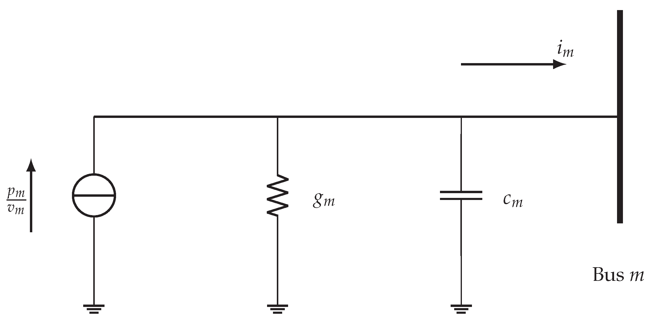
This paper is organized as follows: Section 2 presents MT-HVDC’s mathematical modeling and its dynamic representation for primary control. Section 3 presents the IOC design applied to MT-HVDC systems. Section 4 describes the application of the IOC to MT-HVDC systems. Section 5 presents the simulation results of the proposed control applied to the CIGRE MT-HVDC test system. Finally, in Section 6, the main conclusions derived from this work are named.

2. MT-HVDC Modeling

An MT-HVDC system can be represented with a grid equivalent where all the constant power loads are connected through power electronic converters [27]. To obtain the general dynamic model for the MT-HVDC system, let us consider the general representation for an arbitrary m bus with a constant power load depicted in Figure 1.
In general, the simplified representation of an arbitrary node m with a constant power load is possible by assuming that each load is interfaced through a power electronic converter that allows controlling the current output to maintain constant power generation or consumption [28].
To obtain the general dynamic behavior of the node m, it is applied the first Kirchhoff’s law on it, which produces:
c m v ˙ m = p m v m 1 g m v m i m ,
where c m is the capacitance value, g m is the equivalent conductive effect of a constant resistive load, p m the value of the constant power load consumption, v m is the state variable associated with the voltage at node m, and i m is the current injected to this node.
To obtain an equivalent dynamic model for the whole MT-HVDC system Equation (1) is compacted with its matrix equivalent by assuming that the system has been reduced only to s nodes that include power electronic converters [21]; which generates the following general dynamic grid model.
C s V ˙ s = diag 1 V s P s G s V s I s ,
where C s R s × s is a positive definite diagonal matrix that contains all the capacitive effects of the reduced grid, G s is the reduced conductance matrix which is positive semidefinite (it contains all the conductances in the constant power terminals being a diagonal matrix); V s R s × 1 is the vector of state variables regarding the voltages in all the reduced nodes; and I s R s × 1 is the grid injected current by the constant power terminals in the reduced grid. Please note that diag 1 V s is a matrix with s × s dimensions which is positive definite and contains the inverse of the voltages at each node in its diagonal.
Now, to obtain the equivalent reduced model of the MT-HVDC system, we apply the Kron’s reduction approach by maintaining only the constant power terminals. For this purpose, let us consider the general representation of a DC network with the conductance matrix as presented in Equation (3).
I s I r G s s G s r G r s G r r V s V r ,
where G s s R s × s , G s r = G r s T R s × r , and G r r R r × r are the conductance submatrices that relates nodes with power electronic converters and step- nodes or nodes with pure resistive loads; I r R r × 1 is the current injected in step- and pure resistive loads, and V r R r × 1 correspond to the voltages in these nodes.
To apply the Kron’s reduction, it is assumed that the grid injected current in the step or pure resistive nodes, i.e., I r is null since these effects are completely included in the conductance matrix. Therefore, I r = 0 in (3) produce the following reduction:
I s = G s s G s r G r r 1 G r s V s = H s s V s .
Please note that the dynamical model of the MT-HVDC system can be reached if (4) is substituted in (2), with J s = H s s + G s .
C s V ˙ s = diag 1 V s P s J s V s .
It is worth mentioning that in the case of the steady-state analysis, the dynamic model (5) is reduced to
P s = diag V s J s V s ,
which corresponds to a set of nonlinear algebraic equations known in the specialized literature as the power flow problem [21]. An important fact of this set of equations, is that its solution will provide the equilibrium point where the dynamic model (6) must be stabilized.

3. Global Stabilization via IOC

The inverse optimal control design corresponds to a robust control theory from the family of control Lyapunov functions that allows ensuring asymptotic stability in nonlinear dynamical systems based on an optimal control law [16,17]. Let us consider a general nonlinear dynamical system as follows [29,30]:
x ˙ = f x + g x u , x 0 = x 0
where x R n × 1 is the state vector, u R m × 1 is vector of control inputs, f x : R n × 1 R n × 1 and g x : R n × 1 R n × m are nonlinear functions on the states.
The optimal problem can be formulated as an optimization model with the object of finding an optimal control law u = u that minimizes/maximizes a performance indicator. This indicator can be defined as follows:
J = 0 l x + u T R x u d t
where l x is a positive semidefinite function and R x is positive definite function on the states. Please note that a control law u fulfilling the requirement on J can be defined based on the following theorem [16], where l ( x ) and R 1 ( x ) are defined through the performance indicator; while the nonlinear functions f ( x ) and g ( x ) are provided by the dynamical system (7).
Lemma 1
(Optimality and stability lemma). Consider that there is a positive semidefinite function V ( x ) class C 1 which fulfills the Hamilton-Jacobi-Bellman (HJB) constraint [31]:
l ( x ) + V x f ( x ) 1 4 V x g ( x ) R 1 ( x ) g T ( x ) V x = 0
with V ( 0 ) = 0 , such that the feedback nonlinear controller takes the following form:
u = 1 2 R 1 ( x ) g T ( x ) V x
which allows reaching asymptotically stability at x = 0 . Then, it is possible to affirm that u is the optimal control law that minimizes the function J overall u ensuring that lim t x ( t ) = 0 , being V ( x ) the optimal value function.
Proof. 
In concordance with this result, it must be necessary to solve the HJB equation by finding the function V ( x ) ; however, there is an alternative way to find the optimal control law u without solving the partial differential Equation (9) [16]. In the alternative case, the control law is proposed first, then, the corresponding performance indicator subject to minimization is found [29].
Let us to define the optimal control law u as follows:
u = 1 2 R 1 ( x ˜ ) g T ( x ) V x ˜ ,
where R ( x ˜ ) is a positive definite matrix with symmetrical structure, and x ˜ = x x defines the measure vector of state errors, being x the desired value of the state x. Next, we assume a quadratic function V ( x ˜ ) such that:
V ( x ˜ ) = 1 2 x ˜ T Q x ˜ ,
where Q R n × n is a positive definite matrix with symmetrical structure; that after being partially derived and substituted in (11) produces the following optimal control law
u = 1 2 R 1 ( x ˜ ) g T ( x ) Q x ˜ .
Now, let us suppose that V ( x ˜ ) is considered to be a Lyapunov candidate function, then, the time derivative of this function is as follows [16]:
V ˙ ( x ˜ ) = V x ˜ x ˙ = V x ˜ f ( x ) + V x ˜ g ( x ) u ,
where can be rewritten if we chose u = 1 2 u as presented below.
V ˙ ( x ˜ ) = V x ˜ f ( x ) 1 4 V x ˜ g ( x ) R 1 ( x ˜ ) g T ( x ) Q x ˜ 0 .
Then, to hold (9) it is required that l ( x ˜ ) takes the following structure:
l ( x ˜ ) = V ˙ ( x ˜ ) = V x ˜ f ( x ) + 1 4 V x ˜ g ( x ) R 1 ( x ˜ ) g T ( x ) Q x ˜ 0 ,
which confirm that u in (11) is the optimal control law completing the proof. □
It is worth mentioning that the IOC design is depending on the selection of the Lyapunov candidate function V ( x ˜ ) in (12) and it minimizes the performance indicator (8) always that l ( x ˜ ) fulfills (16) [29].

4. Application of the IOC to MT-HVDC Systems

To ensure the global stabilization of an MT-HVDC system model through the dynamical system (5), let us define the vector of states x ˙ = V ˙ s and the control input as u = P s and the nonlinear functions f ( x ) , and g ( x ) as follows:
f ( x ) = K s J s x ,
g ( x ) = K s diag 1 ( x ) ,
where K s is the inverse of the capacitance reduced matrix C s .
Now, to define the control law, we substitute these functions on (13), the following optimal control law is found.
u = 1 2 R 1 ( x ˜ ) K s diag 1 ( x ) T Q x ˜ ,
where by properties of the diagonal matrices, diag 1 ( x ) T = diag 1 ( x ) and K s = K s T ; and if we select R 1 ( x ˜ ) as K s , then the optimal control law that allows asymptotic stabilization for an MT-HVDC systems takes the following form:
u = 1 2 diag 1 ( x ) Q x ˜ .
Please note that Q can be interpreted as the control gains matrix that will determine the speed of convergence of the voltages in the MT-HVDC system to their references.
Remark 1.
To eliminate the possible steady-state errors produced by the nonlinear proportional optimal control input (20), we add an integral action that does not affects the stability test. The adapted proposed control input takes the following form:
u = 1 2 diag 1 ( x ) Q p x ˜ + Q i z , z ˙ = x ˜ ,
where Q i and Q p represent the integral and proportional control gains, and z is the integral of the measured error between the state variables and the reference signals.
One of the main challenges to determine the optimal references for x is to solve the set of nonlinear Equations (6) using an optimization criterion. Here, we adopt the optimal power flow (OPF) model to obtain these references [28]. The OPF model for an MT-HVDC system takes the following structure:
Obj . Func . min P L = x T H s s x , Subject to : u = P s g P s d = diag ( x ) H s s x , P s g , min P s g P s g , max , x min x x max .
where P s g R n × 1 is the vector of constant power generations, P s d R n × 1 is the vector of constant power consumptions; x min R n × 1 and x max R n × 1 are the vector with the minimum and maximum voltage regulation bounds of the network; and P L is the objective function value associated with the grid power losses.
Please note that the optimization model for the OPF problem is nonlinear and non-convex due to the products among voltage variables. However, these can be solved with a convex approximation based on semidefinite programming (SDP) [28], Second-order cone programming (SOCP) [32], and/or recursive linear approximations [33]; with the main advantage that the returned values for the vector of states (i.e., x ) are indeed the optimal references for the voltages in the reduced MT-HVDC system. Figure 2 illustrates the proposed hierarchical controller to stabilize MT-HVDC systems.
From Figure 2 it is possible to observe that: (i) Constant power terminals n and t are non-controlled constant power consumptions which are associated with the variable P s d in the optimization model (22). These values are forecasted from an economic dispatch analysis; (ii) constant power terminals l, k, m and t are controlled generators that provide electrical power to the grid as a function of the energy availability in the case of renewable energy (i.e., photovoltaic and wind power) or the economic dispatch in the case of thermal power plants; and (iii) the proposed stabilization scheme is a primary-secondary control scheme based on the hierarchical control design using a centralized controller, where the primary control (i.e., the IOC design) is entrusted with the grid stabilization, and the secondary controller is entrusted with the grid optimization (i.e., OPF solution), i.e., of providing the references for the proposed controller.

5. Numerical Implementation

This section presents all the computational validation for our proposed global stabilization method for MT-HVDC systems with the hierarchical control structure shown in Figure 2. All simulations were carried out in MATLAB using its 2021 b version on a PC with an AMD Ryzen 7 3700 2.3 -GHz processor and 16.0 GB RAM, running on a 64-bit version of Microsoft Windows 10 Single Language. The electrical network is implemented with the help of the Simulink/Simscape environment.

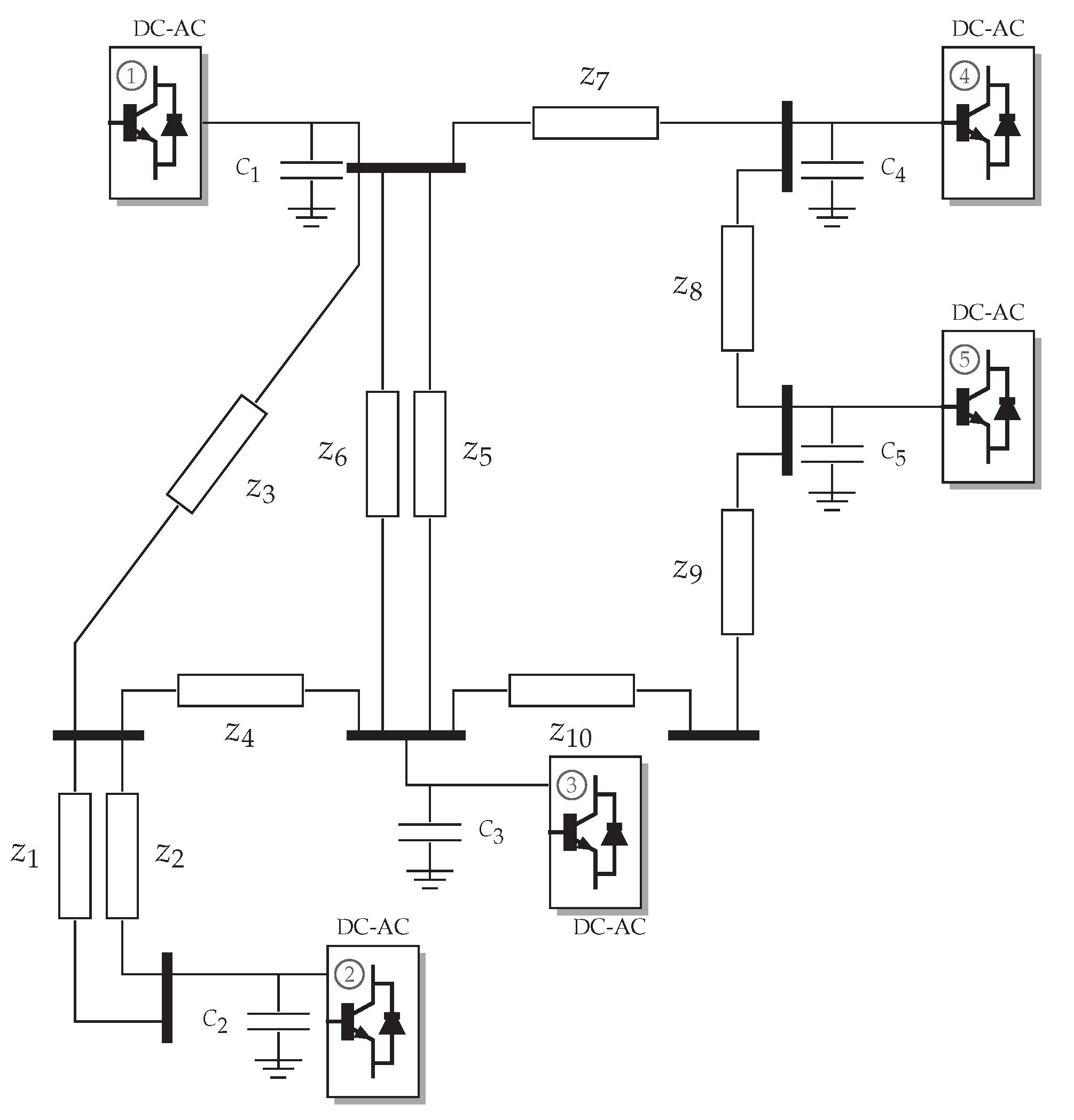
5.1. MT-HVDC System under Analysis and Simulation Cases

To validate the proposed hierarchical control, we consider a reduced version of the CIGRE MT-HVDC system presented in [20]. It is composed of six buses and five power electronic interfaces as presented in Figure 3.
This system is operated with 400 kV, and we assume that the slack source is located at node 1. In addition, the parametric information of the overhead lines and the cables can be consulted in [21]; and the information of the constant power generation and loads is listed in Table 1.
The validation of the proposed hierarchical control design is made through the following simulation cases, which consider a normal operation case and some large disturbance events:
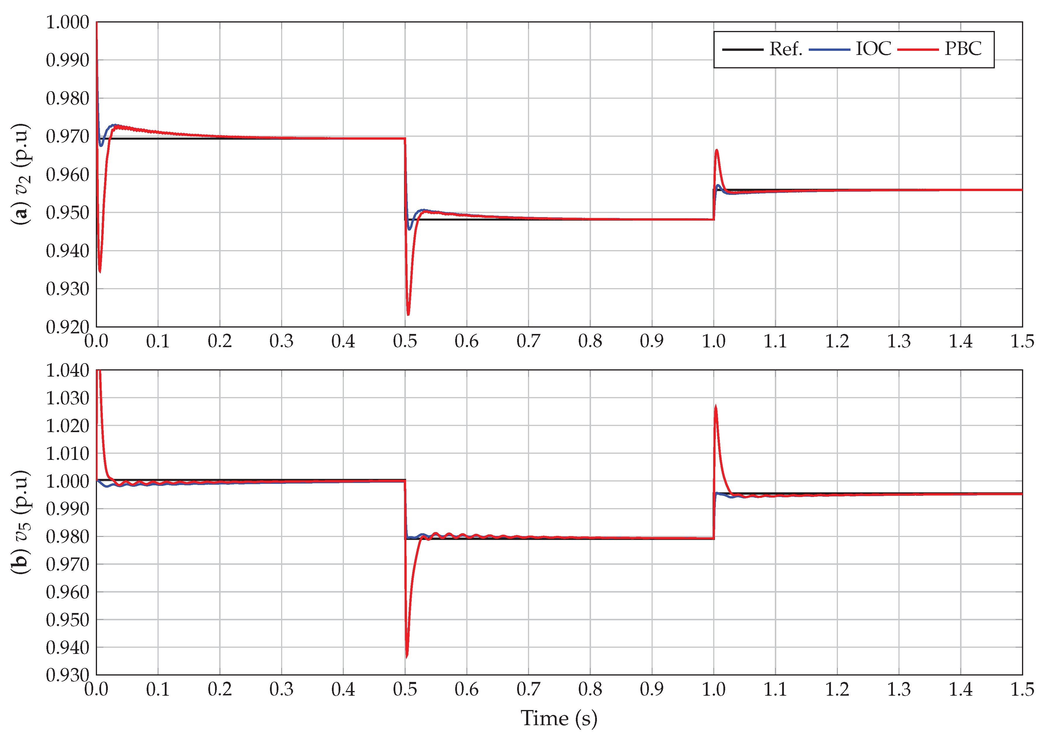
The evaluation of the asymptotic convergence properties of the proposed IOC to reach the references provided by the tertiary control scheme, i.e., the solution of the optimal power flow problem through the SDP approximation. This evaluation is made by introducing three load variations in some constant power terminals that can be caused in the real operation by load changes or variations in the amount of power provided by renewable energy resources (see powers reported in Table 1).
The analysis of a temporary short-circuit event in one of the MT-HVDC system buses with a duration of about 100 ms and a fault resistance of 15 Ω , which for a 400 kV can be considered to be a severe short-circuit event, since currents in the range of tens of thousands of amperes can appear in some areas of the network.
The disconnection of a transmission line due to the incorrect operation of the protective devices in its extremes, which produces a grid topology variation that implies the need for recalculating the reduced conductance matrix to update all the voltage references with the SDP model.

5.2. Voltage Control under Load Variations

To demonstrate the effectiveness of the IOC to stabilize the voltage in all the nodes of the network, we present the voltage variation and its reference for nodes 2 and 5 considering that the proportional and integral gains are set with diagonal values of 20 and 2000, which are multiply by 2 to have the same numerical performance reported in [21]. In addition, we compare the voltage performance reached with the proposed IOC and the passivity-based control (PBC) design presented in [21].
From results in Figure 4, we can observe that: (i) the reference for the voltage profiles have been obtained after solving the optimization model (22) using the CVX tool for semidefinite programming models as recommended in [28]; (ii) in both buses the voltage profile provided by the IOC have lower oscillations at the after the reference variations when compared with the PBC design; which is attributable to the controller form since the PBC control used the d i a g ( x ) of the voltage variables (this amplify the effect of the voltage variations), while the proposed IOC works with the inverse d i a g 1 ( x ) which introduce additional damping when voltage change; and (iii) the settling time in both controllers is the same, which is attributable to the fact that both controllers have tuned equal and both include integral actions that eliminate the steady-state error after reference changing.
To demonstrate that the tertiary control scheme based on the SDP model can ensure the optimal solution of the optimal power flow problem, the complete solution of this problem for all the three load changes defined in Table 2 are listed in Table 1. This table compares the optimal solutions provided by the GAMS software using the KNITRO solver, which is an exact nonlinear optimization tool that allows solving nonlinear programming problems via interior point methods [34], with the solution reached with the SDP approximation [28].
Please note that the solution of the optimal power flow model using the convex proposed reformulation estimates a total power loss of 0.3615 p.u. with a tracking error lower than 2 × 10 4 % in comparison to the exact solution through the KNITRO solver. This result validates the application of the SDP to solve optimal power flow problems in DC networks with optimality properties [35,36].

5.3. Operation under a Short-Circuit Event

To evaluate the numerical performance of the proposed IOC design to maintain the MT-HVDC system stable, we evaluate the effect of a short-circuit event in the bus that connects lines 1 and 4 in Figure 3; and we plot the voltage profile at node 2. The duration of the short-circuit is about 100 ms, and the fault resistance is selected as 15 Ω . Please note that all the power injection adsorptions in constant power loads are set between ± 4000 MW to present the security of each power electronic converter [21].
The behavior of the voltage profile in Figure 5 shows that both controllers have a similar performance during the fault, i.e., between 0.5 s and 0.6 s; however, the PBC approach presents a lower voltage peak when compared with the IOC. On the other hand, when the fault is clarified after 0.6 s, both controllers maintain stable the voltage profile at reference with a recuperation time of about 400 ms with an over-peak at the beginning of the fault clarification about 1.23 pu in both cases.

5.4. Topology Variation

To verify the effectiveness of the IOC in the primary-secondary control stage, we evaluate a topology variation through the simulation of a line disconnection in both extremes due to the incorrect operation of the protective devices. The line disconnected corresponds to line Z 6 . With the new grid topology, the voltage references previous to the disconnection do not minimize the objective function regarding power losses since the equivalent conductance matrix has changed. To evaluate this simulation case, we consider that the system is working in the load conditions associated with the period T 1 presented in Table 1. To show that the system ensures the minimization of the power losses by recalculating the voltage references owing to the grid topology changes, we present the total power injection at the slack source (see Figure 6), i.e., bus 1. It is important to mention that a time delay of 500 ms caused by the communication system traffic is assumed.
Please note that the demeanor of the slack power generation guarantees under steady-state operative conditions that the total grid power losses are minimized since the voltage references provided by the SDP approach in the tertiary control stage are indeed the optimal values for the assigned operative conditions. This implies that previous to the grid topology change, the total power losses of the system are 7.4223 MW as can be seen in Figure 6 before 2 s. During the period between 2.0 s to 2.50 s, the amount of power losses in the network is not minimized since this is a transient time where the main interest of the primary-secondary controller is to maintain the MT-HVDC system stable. Once the conductance matrix was updated and the SDP model was resolved for the new operative conditions, the output power in the slack source is again optimal, which entails that the power losses in steady-state conditions are stabilized in the desired value, i.e., 8.9856 MW.

6. Conclusions and Future Works

The problem of the global stabilization on MT-HVDC systems was addressed in this paper from the IOC method, which allowed dealing with the nonlinearities of the MT-HVDC dynamical model to propose an optimal control law that ensures asymptotic convergence of the state variables to the desired references by adding an integral action to eliminate the steady-state error caused by unmodeled dynamics. Numerical results demonstrate that the IOC design presents a better dynamic performance when compared with the PBC approach since the overshoots that occur when the references’ changes were smaller than the obtained with the PBC approach. A semidefinite approximation of the optimal power flow problem was used to ensure that the MT-HVDC system works on the optimal point. This approach ensures the global optimum reaching due to the convex nature of the solution space with minor errors for the exact nonlinear optimal power flow model. The validation of the effectiveness of the proposed IOC and the SDP on a hierarchical primary-secondary control structure was made under strong disturbances such as a short-circuit and a grid topology variation (line disconnection) that allowed observing that the system remains stable after the fault clarification.
As possible future works, the following research could be conducted: (i) the inclusion of parametric uncertainties in the grid parameters and their effect in the Kron’s reduction matrix; (ii) the inclusion on the centralized control design of the explicit effect of the time-delays between the acquisition data and the control input set adds the possibility of having data lost at the communication level; and (iii) the design of a decentralized control scheme that reduces the dependency on the communication infrastructure using a consensus protocol with local information regarding the neighbor terminals.

Author Contributions

Conceptualization, methodology, software, and writing—review and editing, O.D.M.; W.G.-G.; F.M.S.; C.H.D.A. and J.C.H. All authors have read and agreed to the published version of the manuscript.

Funding

This work was supported in part by the Centro de Investigación y Desarrollo Científico de la Universidad Distrital Francisco José de Caldas under grant 1643-12-2020 associated with the project: “Desarrollo de una metodología de optimización para la gestión óptima de recursos energéticos distribuidos en redes de distribución de energía eléctrica”.

Institutional Review Board Statement

Not applicable.

Informed Consent Statement

Not applicable.

Data Availability Statement

No new data were created or analyzed in this study. Data sharing is not applicable to this article.

Acknowledgments

This work has been derived from the doctoral research project: “Análisis, operación y control de convertidores para la integración de recursos energéticos distribuidos en redes eléctricas aisladas” presented by the student Oscar Danilo Montoya to the Doctoral program of the Engineering Faculty at Universidad Nacional de Rio Cuarto as a partial requirement for the PhD in Engineering Sciences.

Conflicts of Interest

The authors declare no conflict of interest.

References

  1. Alassi, A.; Bañales, S.; Ellabban, O.; Adam, G.; MacIver, C. HVDC transmission: Technology review, market trends and future outlook. Renew. Sustain. Energy Rev. 2019, 112, 530–554. [Google Scholar] [CrossRef]
  2. Xiang, X.; Merlin, M.M.C.; Green, T.C. Cost analysis and comparison of HVAC, LFAC and HVDC for offshore wind power connection. In Proceedings of the 12th IET International Conference on AC and DC Power Transmission (ACDC 2016), Beijing, China, 28–29 May 2016; pp. 1–6. [Google Scholar] [CrossRef]
  3. Elnady, A.; Adam, A. Decoupled State-Feedback Based Control Scheme for the Distributed Generation System. Electr. Power Components Syst. 2018, 46, 494–510. [Google Scholar] [CrossRef]
  4. Serra, F.M.; Angelo, C.H.D. Control of a battery charger for electric vehicles with unity power factor. Trans. Energy Syst. Eng. Appl. 2021, 2, 32–44. [Google Scholar] [CrossRef]
  5. Montoya, O.D.; Gil-González, W.; Garces, A. Optimal Power Flow on DC Microgrids: A Quadratic Convex Approximation. IEEE Trans. Circuits Syst. II Exp. Briefs 2018, 66, 1018–1022. [Google Scholar] [CrossRef]
  6. Yang, W.; Xu, Z.; Han, Z. Co-ordinated hierarchical control strategy for multi-infeed HVDC systems. IEE Proc.-Gener. Transm. Distrib. 2002, 149, 242. [Google Scholar] [CrossRef]
  7. Fan, B.; Wang, K.; Zheng, Z.; Li, Y.; Wu, X. Hierarchical control system of modular multilevel converter used in high-voltage direct current transmission. In Proceedings of the 2014 17th International Conference on Electrical Machines and Systems (ICEMS), Hangzhou, China, 22–25 October 2014. [Google Scholar] [CrossRef]
  8. Ramirez, D.A.; Garcés, A.; Mora-Flórez, J.J. A Convex Approximation for the Tertiary Control of Unbalanced Microgrids. Electr. Power Syst. Res. 2021, 199, 107423. [Google Scholar] [CrossRef]
  9. Egea-Alvarez, A.; Beerten, J.; Hertem, D.V.; Gomis-Bellmunt, O. Primary and secondary power control of multiterminal HVDC grids. In Proceedings of the 10th IET International Conference on AC and DC Power Transmission (ACDC 2012), Birmingham, UK, 4–6 December 2012. [Google Scholar] [CrossRef] [Green Version]
  10. Gil-González, W.; Montoya, O.D.; Garces, A. Direct power control for VSC-HVDC systems: An application of the global tracking passivity-based PI approach. Int. J. Electr. Power Energy Syst. 2019, 110, 588–597. [Google Scholar] [CrossRef]
  11. Simiyu, P.; Xin, A.; Wang, K.; Adwek, G.; Salman, S. Multiterminal Medium Voltage DC Distribution Network Hierarchical Control. Electronics 2020, 9, 506. [Google Scholar] [CrossRef] [Green Version]
  12. Zonetti, D.; Ortega, R.; Benchaib, A. A globally asymptotically stable decentralized PI controller for multi-terminal high-voltage DC transmission systems. In Proceedings of the 2014 European Control Conference (ECC), Strasbourg, France, 24–27 June 2014. [Google Scholar] [CrossRef]
  13. Hannan, M.A.; Hussin, I.; Ker, P.J.; Hoque, M.M.; Lipu, M.S.H.; Hussain, A.; Rahman, M.S.A.; Faizal, C.W.M.; Blaabjerg, F. Advanced Control Strategies of VSC Based HVDC Transmission System: Issues and Potential Recommendations. IEEE Access 2018, 6, 78352–78369. [Google Scholar] [CrossRef]
  14. Simorgh, A.; Razminia, A.; Mobayen, S.; Baleanu, D. Optimal Control of a MIMO Bioreactor System Using Direct Approach. Int. J. Control. Autom. Syst. 2021, 19, 1159–1174. [Google Scholar] [CrossRef]
  15. Mobayen, S. Optimal LMI-based state feedback stabilizer for uncertain nonlinear systems with time-Varying uncertainties and disturbances. Complexity 2016, 21, 356–362. [Google Scholar] [CrossRef]
  16. Vega, C.; Alzate, R. Inverse optimal control on electric power conversion. In Proceedings of the 2014 IEEE International Autumn Meeting on Power, Electronics and Computing (ROPEC), Ixtapa, Mexico, 5–7 November 2014. [Google Scholar] [CrossRef]
  17. Johnson, M.; Aghasadeghi, N.; Bretl, T. Inverse optimal control for deterministic continuous-time nonlinear systems. In Proceedings of the 52nd IEEE Conference on Decision and Control, Firenze, Italy, 10–13 December 2013. [Google Scholar] [CrossRef]
  18. Raza, A.; Shakeel, A.; Altalbe, A.; OAlassafi, M.; Yasin, A.R. Impacts of MT-HVDC Systems on Enhancing the Power Transmission Capability. Appl. Sci. 2020, 10, 242. [Google Scholar] [CrossRef]
  19. Mohammadi, F.; Nazri, G.A.; Saif, M. An improved droop-based control strategy for MT-HVDC systems. Electronics 2020, 9, 87. [Google Scholar] [CrossRef] [Green Version]
  20. Gavriluta, C.; Candela, I.; Citro, C.; Luna, A.; Rodriguez, P. Design considerations for primary control in multi-terminal VSC-HVDC grids. Electr. Power Syst. Res. 2015, 122, 33–41. [Google Scholar] [CrossRef]
  21. Montoya, O.D.; Gil-González, W.; Garces, A.; Serra, F.; Hernández, J.C. Stabilization of MT-HVDC grids via passivity-based control and convex optimization. Electr. Power Syst. Res. 2021, 196, 107273. [Google Scholar] [CrossRef]
  22. De Persis, C.; Weitenberg, E.R.; Dörfler, F. A power consensus algorithm for DC microgrids. Automatica 2018, 89, 364–375. [Google Scholar] [CrossRef] [Green Version]
  23. Tucci, M.; Meng, L.; Guerrero, J.M.; Ferrari-Trecate, G. Stable current sharing and voltage balancing in DC microgrids: A consensus-based secondary control layer. Automatica 2018, 95, 1–13. [Google Scholar] [CrossRef]
  24. Magne, P.; Nahid-Mobarakeh, B.; Pierfederici, S. General Active Global Stabilization of Multiloads DC-Power Networks. IEEE Trans. Power Electron. 2012, 27, 1788–1798. [Google Scholar] [CrossRef]
  25. Vafamand, N.; Khooban, M.H.; Dragičević, T.; Blaabjerg, F. Networked Fuzzy Predictive Control of Power Buffers for Dynamic Stabilization of DC Microgrids. IEEE Trans. Ind. Electron. 2019, 66, 1356–1362. [Google Scholar] [CrossRef]
  26. Kardan, M.A.; Asemani, M.H.; Khayatian, A.; Vafamand, N.; Khooban, M.H.; Dragičević, T.; Blaabjerg, F. Improved Stabilization of Nonlinear DC Microgrids: Cubature Kalman Filter Approach. IEEE Trans. Ind. Appl. 2018, 54, 5104–5112. [Google Scholar] [CrossRef] [Green Version]
  27. Mahmoudi, H.; Aleenejad, M.; Ahmadi, R. Modulated model predictive control of modular multilevel converters in VSC-HVDC systems. IEEE Trans. Power Del. 2017, 33, 2115–2124. [Google Scholar] [CrossRef]
  28. Garces, A.; Montoya, D.; Torres, R. Optimal power flow in multiterminal HVDC systems considering DC/DC converters. In Proceedings of the 2016 IEEE 25th International Symposium on Industrial Electronics (ISIE), Santa Clara, CA, USA, 8–10 June 2016. [Google Scholar] [CrossRef]
  29. Sepulchre, R.; Janković, M.; Kokotović, P.V. Constructive Nonlinear Control; Springer: London, UK, 1997. [Google Scholar] [CrossRef] [Green Version]
  30. Alanis, A.Y.; Lastire, E.A.; Arana-Daniel, N.; Lopez-Franco, C. Inverse Optimal Control with Speed Gradient for a Power Electric System Using a Neural Reduced Model. Math. Probl. Eng. 2014, 2014, 1–21. [Google Scholar] [CrossRef]
  31. Pérez, C.J.V.; Castaño, R.A. Inverse optimal control as an alternative to regulate a Boost DC-DC power converter. Rev. Tecnura 2015, 19, 65. [Google Scholar] [CrossRef] [Green Version]
  32. Li, J.; Liu, F.; Wang, Z.; Low, S.H.; Mei, S. Optimal Power Flow in Stand-Alone DC Microgrids. IEEE Trans. Power Syst. 2018, 33, 5496–5506. [Google Scholar] [CrossRef] [Green Version]
  33. Montoya, O.D.; Gil-González, W.; Garces, A. Sequential quadratic programming models for solving the OPF problem in DC grids. Electr. Power Syst. Res. 2019, 169, 18–23. [Google Scholar] [CrossRef]
  34. Gil-González, W.; Molina-Cabrera, A.; Montoya, O.D.; Grisales-Noreña, L.F. An MI-SDP Model for Optimal Location and Sizing of Distributed Generators in DC Grids That Guarantees the Global Optimum. Appl. Sci. 2020, 10, 7681. [Google Scholar] [CrossRef]
  35. Gil-González, W.; Montoya, O.D.; Holguín, E.; Garces, A.; Grisales-Noreña, L.F. Economic dispatch of energy storage systems in dc microgrids employing a semidefinite programming model. J. Energy Storage 2019, 21, 1–8. [Google Scholar] [CrossRef]
  36. Montoya, O.D. Numerical Approximation of the Maximum Power Consumption in DC-MGs with CPLs via an SDP Model. IEEE Trans. Circuits Syst. II Exp. Briefs 2018, 66, 642–646. [Google Scholar] [CrossRef]
Figure 1. Reduced model for a node with a constant power load [21].
Electronics 10 02819 g001
Figure 2. Hierarchic controller design via OPF and IOC.
Electronics 10 02819 g002
Figure 3. MT-HVDC grid developed by the CIGRE B4 working group.
Electronics 10 02819 g003
Figure 4. Voltage profiles at nodes 2 and 5. (a) voltage profile at node 2, and (b) voltage profile at node 5.
Electronics 10 02819 g004
Figure 5. Effect on the voltage profile at node 2 when a short-circuit fault with 15 Ω occurs at node between lines 1 and 4.
Electronics 10 02819 g005
Figure 6. Output power at the slack source, i.e., bus 1.
Electronics 10 02819 g006
Table 1. Demand and generation information for three periods of time.
NodeT1 (MW)T2 (MW)T3 (MW)
1 Slack
2 CPL85015001200
3 CPL150014002000
4 CPL185023501500
5 PV25505001250
Table 2. Comparisons among voltages provided by the GAMS/KNITRO solver and the SDP approximation.
GAMS-KNITRO
Period [s] v 2 (p.u) v 3 (p.u) v 4 (p.u) v 5 (p.u)
T10.969403870.982778740.989174121.00054847
T20.948127890.973595050.975245390.97910535
T30.955876390.974899930.988586840.99519122
CVX-MATLAB
Period [s] v 2 (p.u) v 3 (p.u) v 4 (p.u) v 5 (p.u)
T10.969360160.982719700.989065061.00034174
T20.948127840.973595050.975245440.97910548
T30.955925690.974967180.988709120.99543415
Publisher’s Note: MDPI stays neutral with regard to jurisdictional claims in published maps and institutional affiliations.

