Review

An Overview of Wearable Piezoresistive and Inertial Sensors for Respiration Rate Monitoring

1
Department of Innovation Engineering, University of Salento, 73100 Lecce, Italy
2
Center for Biomolecular Nanotechnologies, Italian Technology Institute IIT, 73010 Arnesano, Italy
3
Facultad de Ingeniería, Universidad Panamericana, Aguascalientes 20290, Mexico
*
Author to whom correspondence should be addressed.
Electronics 2021, 10(17), 2178; https://doi.org/10.3390/electronics10172178
Submission received: 4 August 2021 / Revised: 28 August 2021 / Accepted: 3 September 2021 / Published: 6 September 2021
(This article belongs to the Special Issue 10th Anniversary of Electronics: Hot Topics in Bioelectronics)

Abstract

:
The demand for wearable devices to measure respiratory activity is constantly growing, finding applications in a wide range of scenarios (e.g., clinical environments and workplaces, outdoors for monitoring sports activities, etc.). Particularly, the respiration rate (RR) is a vital parameter since it indicates serious illness (e.g., pneumonia, emphysema, pulmonary embolism, etc.). Therefore, several solutions have been presented in the scientific literature and on the market to make RR monitoring simple, accurate, reliable and noninvasive. Among the different transduction methods, the piezoresistive and inertial ones satisfactorily meet the requirements for smart wearable devices since unobtrusive, lightweight and easy to integrate. Hence, this review paper focuses on innovative wearable devices, detection strategies and algorithms that exploit piezoresistive or inertial sensors to monitor the breathing parameters. At first, this paper presents a comprehensive overview of innovative piezoresistive wearable devices for measuring user’s respiratory variables. Later, a survey of novel piezoresistive textiles to develop wearable devices for detecting breathing movements is reported. Afterwards, the state-of-art about wearable devices to monitor the respiratory parameters, based on inertial sensors (i.e., accelerometers and gyroscopes), is presented for detecting dysfunctions or pathologies in a non-invasive and accurate way. In this field, several processing tools are employed to extract the respiratory parameters from inertial data; therefore, an overview of algorithms and methods to determine the respiratory rate from acceleration data is provided. Finally, comparative analysis for all the covered topics are reported, providing useful insights to develop the next generation of wearable sensors for monitoring respiratory parameters.

1. Introduction

Wearable sensors are becoming increasingly popular, allowing continuous and unobtrusive monitoring of many biophysical and environmental parameters for different applications and operative scenarios, thus improving users’ life quality and preventing diseases [1,2]. In this field, the Internet of Things (IoT) represents a milestone on which the future health system will be built, combining wearable sensing devices with cloud and fog computing, predictive and inferring techniques [3,4].
Respiration rate (RR) is a crucial parameter to be monitored under different conditions because it is an indicator of severe diseases (pneumonia, emphysema, pulmonary embolism, apnea, etc.), even more so, considering the global COVID-19 pandemic that is heavily affecting our lives [5]. The use of wearable devices to monitor breathing activity has paved the way for a slew of new medical services, enabling remote, accurate and local monitoring of the patient’s conditions. Several wearable sensors have been proposed in the scientific literature and on the market to detect respiratory parameters, exploiting different transduction mechanisms to detect chest movements, exhaled gases, blood oxygenation changes or emitted sounds. Also, numerous signal processing techniques for breathing analysis have been reported to extract useful information from raw data.
Acoustic, resistive, inductive, humidity, inertial, vibration, electromyography (EMG), impedance, and infrared sensor technologies are standard transducing methods to detect pulmonary activity. Wearable sensors for respiratory monitoring usually use various electronic sensors integrated into belts [6,7], worn on the skin [8,9], or mounted into clothing [10]. Pressure sensors can be employed to build wearable devices exploiting the diaphragm contraction and relaxation. They are attached to a belt so that when the chest expands during breathing, it exerts a force on the sensor, resulting in voltage changes proportional to the movement [7]. Alternatively, the pressure sensors can be placed in direct contact with the inhaled and exhaled air pressures while breathing. However, since body movements affect measurement accuracy, the sensor only worked well for still or moderately moving patients [7]. The facemask sensors also worked admirably, accurately estimating respiratory impedance; nonetheless, their main limitation is the lack of comfort [11]. In addition, the analysis of inhaled/exhaled air components is another innovative strategy for monitoring respiratory activity. Specifically, the variation in oxygen and carbon dioxide (CO2) content between inspiration and expiration can be exploited to measure the RR [12]; infrared and fibre-optic sensors are common strategies for detecting CO2 [13,14]. Acoustic sensors can be used to detect lung sounds. A microphone near the nose, mouth, throat and suprasternal notch is commonly used to obtain acoustic signals related to breathing [8,15,16]. Acoustic wearable sensors have many potentials; however, some issues arise during the design phase related to sensor location, background noise cancellation, and detecting moving objects. Also, the capacitive transduction method is a novel technology that can be exploited for monitoring chests movements. In [17], a low-cost wearable respiratory system was developed to detect breathing activity using a flexible and stretchable capacitive sensor constituted by a bifilar helix of conductive wires sealed in an insulating tube and mounted on an elastic band applied on the user’ chest. The obtained device showed high resolution, low cost, vibration-immunity and low power consumption.
The measurement of blood oxygen saturation (SpO2) is called oximetry; it relies on an infrared emitter that illuminates a small skin area and a receiver to detect light absorption based on blood oxygenation and deoxygenation levels [18]. Wearable oximetry sensors are widely commercialized and applied on the wrist, finger, head, earphones, earlobe, thigh, and foot [19]. Also, several algorithms are reported in the literature to extract the RR from the ECG (Electrocardiogram) usually detected by clinical instrumentations and wearable devices (e.g., smartwatch, smart band, etc.). All of them are based on the analysis of the three respiratory modulations featuring the ECG and PPG [20].
Accelerometers can be used to record inhalation and exhalation motions [21]. Since muscle contractions during breathing are unique for each individual, a stronger signal can be produced based on the sensor position [22,23]. Also, accelerometers are featured by a broad spectral spectrum and small sizes; for these reasons, they recently found use in various fields [24,25]. Nevertheless, body movement has a significant impact on the detected data, limiting the applicability of this approach [26]. The sensitivity can be adjusted to detect vibrations ranging from large body movements to minor artery pulsation.
A textile sensor was used in [27] to detect talk events based on changes in breathing patterns. Resistive strain sensors made of a conductive material and polymer mixture were used in the proposed solution. These sensors were applied to the upper chest, lower chest, and abdominal using elastic belts, changing their resistance due to thoracic or abdominal expansion and relaxation; movement artefacts are the main issue with this type of sensor. Considerable efforts are made to integrate these sensors into clothing to develop the next generation of wearable for healthcare applications, allowing monitoring biophysical parameters, for instance, during running and cycling [6,28,29].
Among the contact-less technologies for respiratory monitoring, radar, thermal sensors, or optical sensors should be mentioned [30]; also, the camera-based approaches to extract the breathing signal from the observation of chest and abdomen motions is an excellent strategy for remote healthcare applications [31,32]. However, they suffer from heavy dependence on clothing and environmental lighting.
Table 1 summarizes the advantages and limitations of the transduction methods above described for detecting the RR.
This review paper focuses on wearable piezoresistive and inertial-based devices, detection strategies and algorithms for detecting the RR, given their excellent potentialities related to lightness, non-invasiveness and high sensitivity. We believe that providing the readers with a detailed analysis of only these two detection strategies can lead to a better understanding of the discussed topics than other similar review papers, which present wide overviews of multiple transduction mechanisms and technologies. Therefore, up-to-date overviews of devices, materials, and algorithms using piezoresistive and inertial sensors for detecting respiratory parameters are reported, providing for each treated topic a comparative analysis for highlighting the strengths and limitations of discussed technologies.
Smart fabrics and layers are attracting great attention in the scientific community since pleasant and non-intrusive for developing wearable sensors in various application fields, including healthcare, sports, and military applications [33,34,35]. In particular, piezoresistive fabrics are well suited for integrating wearable devices for their easy-to-implement nature, low cost, and high sensitivity. Also, the strength of inertial sensors lies in their versatility and non-invasiveness, making them ideal for various applications, representing a reliable and inexpensive way for collecting user’s motion data; the most important field is undoubtedly health monitoring [36,37,38].
The main contributions of the proposed review work are:
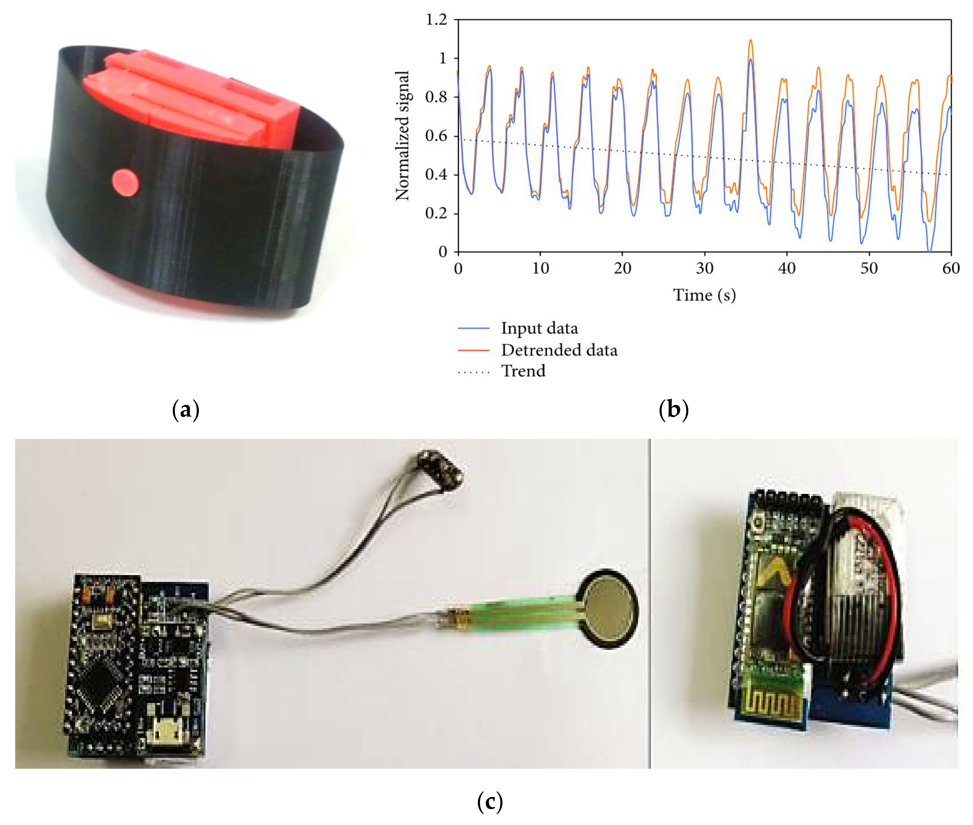
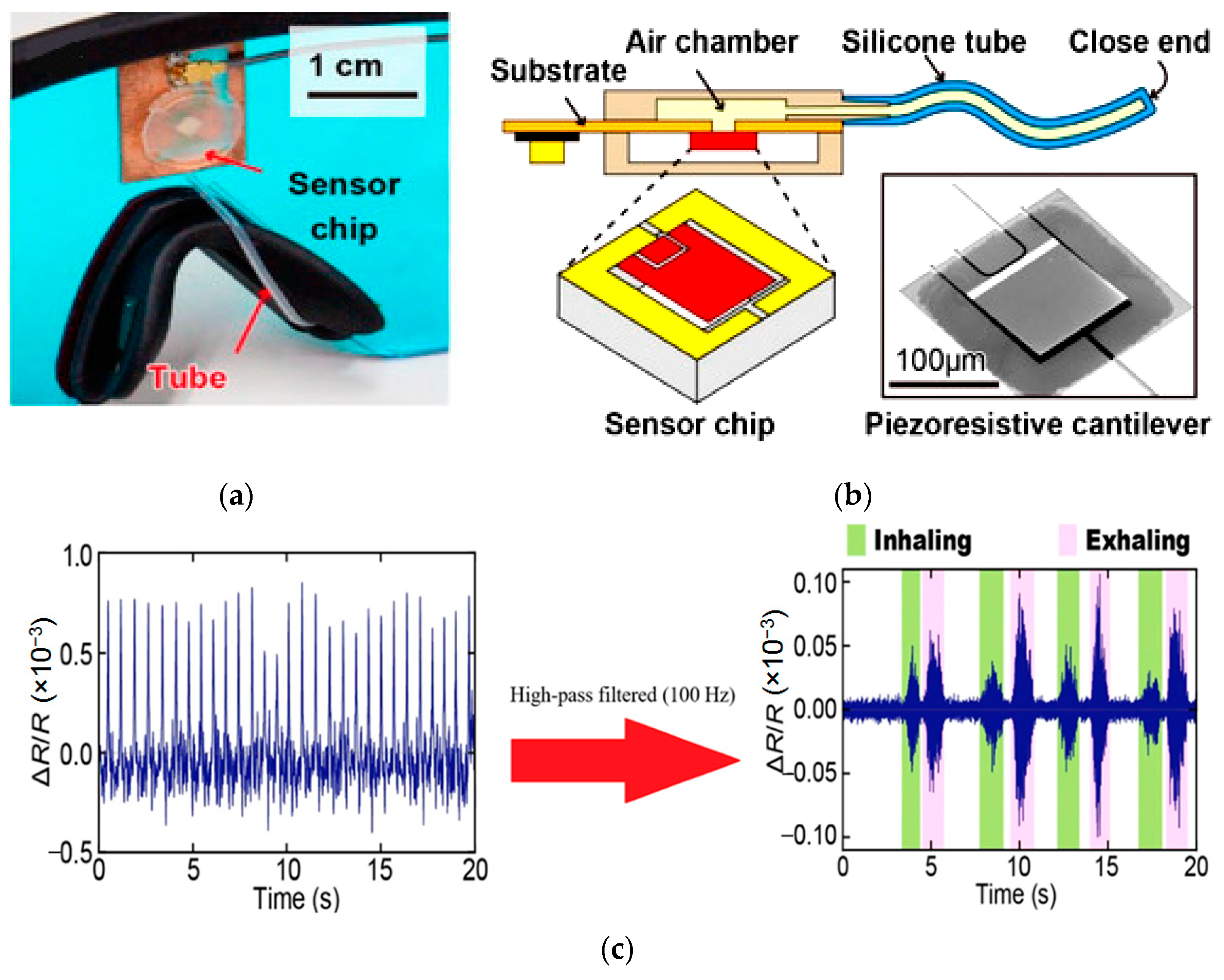
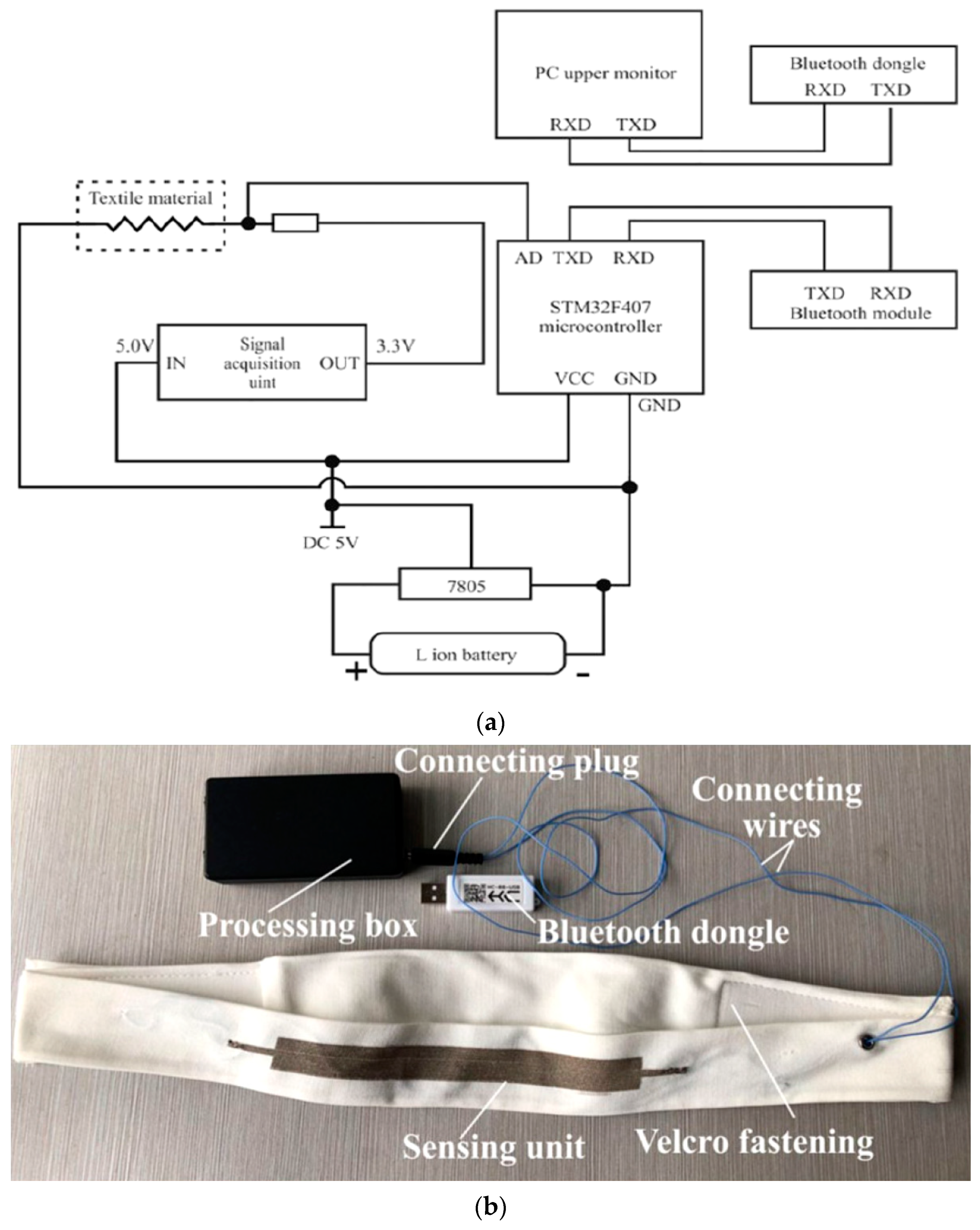
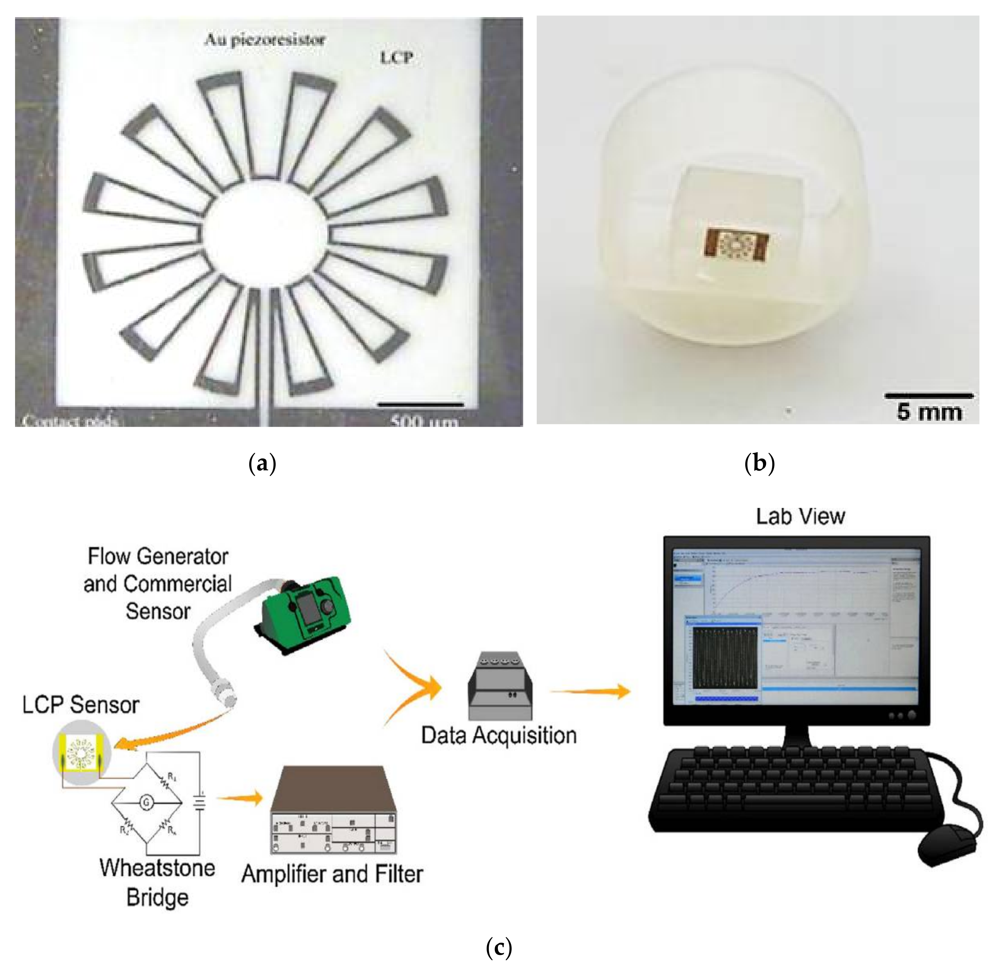
  • A comprehensive overview of the methodologies, materials, and techniques applied to piezoresistive breathing sensors. Specifically, novel IoT-based wearable devices for monitoring respiration activity are discussed and analyzed [19,39]. Also, innovative piezoresistive materials are introduced, analyzing their manufacturing processes and improvements enhancing their performances or reduce production costs or, last but not least, improve user’s experience by making the sensor more comfortable. Furthermore, we report a comparative analysis of discussed piezoresistive devices to define the features and functionalities of the next generation of RR sensors.
  • An accurate survey of IoT-based wearable devices using inertial sensors (accelerometers, gyroscope, magnetometer, etc.) are analyzed for detecting the breathing movements and thus extracting the respiration rate [40,41,42]. Several embedded systems are proposed in the scientific literature, including one or more inertial sensors, a processing unit, and a communication module for wirelessly transmits the acquired data toward a host device or cloud platform, allowing remote monitoring of user’s conditions [43,44]. Furthermore, an overview of the main algorithms for extracting the respiratory rate from the raw inertial data is reported. Finally, a comparison of discussed devices based on inertial sensors is reported.
The proposed review paper is arranged as follows: Section 2 reports an overview of innovative devices, methodologies, and materials based on piezoresistive RR sensors; furthermore, a comparative analysis of discussed piezoresistive-based devices and materials are presented. Later, Section 3 presents a survey of wearable systems and algorithms for measuring breathing activity using inertial sensors. Finally, a critical analysis of the discussed inertial-based wearable sensors and algorithms are introduced.

2. Review of Innovative Piezoresistive System and Materials for Detecting the Respiration Rate

Piezoresistive sensors rely on the piezoresistive effect exhibited by some materials when subjected to mechanical stress. Indeed, this effect involves the reversible change of electrical resistance (i.e., R = ρ·l/A where ρ is the resistivity [Ω·cm], l the sample length [cm], and A the sample cross-section [cm2]) as a consequence of applied stimulus, mainly due to the variations of geometrical parameters; however, in some semiconductors and metals, the resistance change is caused by ρ variation [45].
At first, this section reports a comprehensive analysis of innovative piezoresistive sensing systems for monitoring the patient’s respiratory activity, widely exploiting wearable devices and IoT solutions. Afterwards, we presented an overview of smart textiles and materials applied to respiration monitoring. Finally, at the end of each subsection, a comparative analysis of the discussed systems and materials is reported to highlight analogies and differences, providing insights for developing the next generation of RR sensing systems.

2.1. A Survey of Innovative Piezoresistive Sensing Systems for Monitoring the Respiratory Activity

The diagnosis of sleep apnea and RR assessment are both crucial aspects of respiratory monitoring. Other respiratory rehabilitation treatments, such as magnetic resonance exams for respiratory induced imaging and coordinated functional electrical stimulation, rely on automated identification of breathing patterns. This section discusses the state-of-art of piezoresistive systems and materials for detecting breathing movements.
The resistive respiratory sensors are commonly applied on the chest walls since they detect deformations related to respiratory movements. In [46], the authors demonstrated that the performance of piezoresistive sensors improves when positioned on the upper thorax, also resulting in less affected by motion artefacts than the abdominal zone during daily life activities (e.g., walking, running, etc.). In addition, this positioning ensures good device usability and satisfaction from users, as stated in [47,48]. Also, in [49], a survey about the usability of two smart textile systems (a smart undershirt and smart socks). The usability tests demonstrated that a large percentage (44.4%) of participants preferred “any garment” on their body; the most appreciate solutions for smart textile systems were short-sleeved T-shirts, wristbands, socks, sleeveless T-shirts, and ankle sleeves.
In [50], E. Vanegas et al. proposed a novel wearable system for RR monitoring based on a piezoresistive transducer (Model A201 FlexiForce). Notably, the sensor has been enclosed inside a plastic case realized by 3D printing, also containing the microcontroller (Arduino Pro Mini), the energy storage device (150 mAh LiPo Battery), and the Bluetooth module (HC-05 Module) (Figure 1c). The resulting device was compact (73 mm × 45 mm × 37 mm) and lightweight (only 103 g) (Figure 1a). Furthermore, the authors proposed two algorithms to calculate the RR from the data acquired to 50 Hz sampling frequency on a given time window (w) (Figure 1b).
These last have been transmitted to a PC and offline processed using MATLAB. At first, the data were filtered by a 0.5 Hz low-pass filter to remove the high-frequency noise; since a breathing rate above 30 BrPM (Breath Per Minute) is uncommon in daily activities, this cut-off frequency was chosen. Afterwards, the Zero Axis (ZA) value on a given analyzed time window was calculated as:
ZA = min x + max x 2
where x was the array of preprocessed data. The ZA was used as a reference value for the following zero-crossing detection process, which detected zero crossings considering a couple of values and assessing that they satisfied the following inequalities and storing, if verified, the corresponding instant. The first proposed method calculated the RR from the Mean Time Difference (MTD) between zero crossings.
RR = 30 MTD  
The second method relied on the number of zero crossings (N) inside the w time window:
RR = 30 N w
where the 30 term is due to the two zero crossings within a breathing cycle. The device was tested on 21 subjects to determine its reliability; the obtained results demonstrated that a time window of 27 s produced the best performances. If a shorter time window was selected, a slightly higher error was obtained.
In [51], Saha et al. presented a low-cost lung monitoring device featured by high reliability and low cost. The result was a comfortable cylindrical mouthpiece constituted by a sensor a then electronics for signal processing. The solution comprised a piezoresistive sensor made of two thin layers (200 µm) of polydimethylsiloxane (PDMS), allowing a large range of bending while protecting the graphene layer. There were copper contacts among the PDMS layers and the thick graphene layer responsible for the piezoresistive behaviour. The sensor was mounted on top of a cylindrical body with 15 cm length and 2.5 cm inner diameter, placed into a bulge to store the electronic components; finally, the tube had a honeycomb filter to steer the airflow. The flow rate was derived by Equation (4):
Q = v × A
where Q is the flow rate measured in liters per minute (L/min), v is flow speed, and A is the section area. The experimental results demonstrated the suitability of the developed device for analyzing and detecting respiratory activity in the domestic environment, making it possible to monitor our healthcare through our smartphones in a cheaper and more accessible way.
Furthermore, in [52], T.V. Nguyen and M. Ichiki developed an easy-to-mount and comfortable device to simultaneously measure heart rate and RR using a single sensing element, taking advantage of the piezoresistive behaviour. The microelectromechanical system (MEMS)-based pressure sensor was mounted on a pair of eyeglasses, causing minor complaints to the wearer (critical for sports usage) (Figure 2a). The heartbeat and breathing cause a change in the tube’s inner pressure due to the skin vibrations attached to the eyeglasses’ nose pad. To measure these pressure changes, they used a solution preventing the piezoresistive cantilever from breaking (it has been tested for four months). The cantilever was placed in an air chamber connected with a silicon tube, making the sensor sensible to the internal pressure changes (Figure 2b); a Wheatstone bridge circuit was used to evaluate the resistance changes.
The experimental results proved that this type of sensor has a resolution as small as 0.01 Pa. The sensor transfer characteristic was expressed by the following Equation (5):
Δ R R = 7 × 10 4 Δ P
To extract the information due to the pulse wave and RR, they noted that the breathing signal had a frequency notably higher than the pulse-induced one, ranging from 100 to 400 Hz. Therefore, an easy solution was to filter the acquired signal by a high-pass filter with a cut-off frequency of 100 Hz (Figure 2c).
Up until now, we have focused on breathing sensor that exploits the piezoresistive working principle. However, in [53], R. K. Raji et al. studied respiration patterns of 20 users in different scenarios to investigate the influences of gender, ethnicity, test periods, body mass index (BMI), and posture or physical activities.
To measure the most common indicators in pneumography, like breath volume (BV), moment ventilation (MV), respiratory cycle (RC) and inspiratory duty cycle (DTCY), the authors used the KTC system. This last comprises an ARM Cortex-M3 STM32F401RCT6 microcontroller board for signal processing, two Li-Ion rechargeable batteries, a piezoresistive sensor knitted on a velcro strap, a signal acquisition circuit for converting the digital values from strain sensor signals, and an HC-08 Bluetooth 4.0 BLE (Bluetooth Low Energy) module for wirelessly transmitting the acquired data (Figure 3).
From the obtained measurements, filtered and refined to get the most balanced point of view, it has been noted that respiration patterns were subject to change based on the carried out activity. The respiration pattern was notably different due to RCs rates and metabolism, augmented when sports were performed. Despite what is known about male properties, no evident diversity was found between men and women, and neither ethnicity and period of the day played an important role. Finally, after a total of 67 days of testing, this study made clear that breath patterns were subject to the performed activity and BMI (Body Mass Index), thus not attributable to gender or ethnicity.
Using an artificial neural network (ANN), the same authors, in [54], developed a new respiration pattern-based biometric prediction method (BPS). The ANN model was implemented with four hidden layers to achieve the best complexity for an excellent data fit. This study provided a comprehensive distribution of an ANN model’s construction, including the scheme of parameters and network layers, design ablation, and back-propagation derivation during iterations. Also, the model used a step-based decay to systematically drop the learning rate after particular epochs during training to reduce loss and increase the model’s accuracy.
The KTC band collected the respiration information, used to train ANN computational model according to the standard splitting process (70% training instances and 30% testing instances); finally, the user’s identity was appropriately predicted, setting the learning rate. The proposed model was tested on ten users in three main circumstances (standing, sitting, and reading). The experimental results demonstrated that the ANN model correctly identified 51,338 instances on a set of 51,557 tests.
In [55], Abbasnejad et al. employed a MEMS liquid crystal polymer (LCP) included in a membrane-based pressure sensor for realizing an excellent flow sensor (Figure 4a). The authors used an airflow generator to perform a series of experiments to explore the ability of the proposed LCP flow sensor for sleep apnea monitoring. The sensor is constituted by an LCP membrane, featured by higher sensitivity and stability than silicon due to its lower Young’s modulus (i.e., 2.16 GPa vs. 185 GPa) [56].
Furthermore, LCP has high chemical stability and low moisture absorption capability, making the sensor suitable for harsh environments. LCP silicon wafer bonding, deep reactive-ion etching (DRIE) for through-hole forming, sputtering a metal resistor, and lift-off for resistor patterning were the four main steps for the sensor fabrication [57]. The piezoresistive LCP flow sensor was a micro diaphragm unit with a 25 µm thick circular sensing membrane with a 2000 µm diameter. On the LCP membrane’s periphery, where the maximum stress is produced, 100 nm thick gold strain gauges with a serpentine shape were deposited. A circular housing to handle the tube was 3D printed, placing the sensor at the end of the flow generator’s pipe (Figure 4b). The LCP sensor was connected to an external Wheatstone bridge, followed by a 50 gain amplifier and a 3 Hz low pass filter (Figure 4c). The experimental results demonstrated that the LCP flow sensor was suitable for detecting human respiration since it has a low minimum detectable flow (i.e., 8 LPM), lower than the industrial flow sensor (>10 LPM), high sensitivity, and resolution. Also, the LCP flow sensor is featured by a good response over a broad flow range (8 ÷ 160 LPM) and a linear voltage response with 0.004 V/LPM sensitivity.
In [58], Zheng et al. have developed highly stretchable graphene foam (GF)/PDMS composite films with tunable sensitivities and switching capabilities by simply manipulating the thickness of graphene foam (GF). The GF/PDMS composite films were featured by a high gauge factor (i.e., 24 at a 10% pressure), tunable stretchability (i.e., up to 70%), and supporting an on/off switching ratio of 1000. Particularly, the authors cut similar GFs into composite films with different thicknesses (i.e., 200, 400, 800, and 1600 µm); the resistance of the composite films was increased by over two orders of magnitude, from 149 Ω to 19.3 kΩ, by reducing the thickness of the composite films. The resistance change increased by lowering the composite film thickness providing a simple and easy way to tune the sensitivity. Furthermore, the sensors were combined with electronic sections for signal conditioning and preprocessing, wireless communication, and post-processing, enabling data transmission to a smartphone through a custom-developed application. The developed material was applied to fully integrated human motion monitoring devices, including composite sensors, a signal analyzer, a Bluetooth transmitter, and a smartphone; specifically, the developed sensors were tested to detect neck movements, breathing, and gait [59].
Furthermore, some solutions are present in the scientific literature that combine a piezoresistive sensing system and inertial sensors for removing motion artefacts. For instance, in [60], the authors proposed a novel data fusion algorithm for removing the motion artefacts from the breathing signal acquired through four piezoresistive textiles sensors. Particularly, the signals of piezoresistive and IMUs (i.e., 3-axis accelerometer and gyroscope) are fused and jointly processed by ICA (Independent Component Analysis) to discern the respiratory signal component from those related to the human motion. Also, M. Chu et al. developed a wearable sensor to measure respiration rate and volume by detecting the strain on the ribcage and abdomen [61]. The authors used a strain sensor constituted by a thin metal film deposited on a silicon substrate [62], which relies on a transduction method based on controlled disgregation of the film, inducing the increase of the sensor’s resistance. This last was featured by an operative range of 156% ÷ 226%, a gauge factor from 0.85% to 2.64%, and a lifetime up to 2000 cycles. Two strain sensors were placed on the abdomen and the torso (Figure 5a); their resistances were converted by Wheatstone bridges and collected by an acquisition data system (Figure 5b). The authors used the method developed in [63] for measuring the respiration rate and volume, previously calibrating the acquisition system for each subject. Also, a 3-axis accelerometer was applied to the sternum to measure the user’s movements and delete the motion artefacts, as detailed in Section 3.1. In addition, in [64], R. Marani et al. developed a new combined acquisition system for monitoring respiration rate and activity level, using a piezoresistive band and a low-cost accelerometer. Specifically, a Xilor rubber sample was included in a breast belt, supported by a non-conductive flexible layer. The strain-sensitive signal was conditioned, acquired and processed by a peak detector to determine the pulse length and thus the breathing rate. Besides, a 3-axis accelerometer (i.e., ADXL103) was used to detect the user position (i.e., standing, sitting, lying down) and measure the kinetic activity by filtering and averaging the inertial signal.
In [65], C. Massaroni et al. developed an innovative device for monitoring respiratory activities, including six piezoresistive sensors. These last were made of 89% silver and 11% spandex piezoresistive silver-plated knitted fabric. Intermeshed conductive zones were generated by knitting silver conductive yarns into the base structure. The resulting material was featured by 0.15 Ω zero-pressure resistance, reaching a maximum value of 0.5 Ω under pressure, and mass per unit area of approximately 346 g∙m−2. The six sensors were arranged to monitor movements of the pulmonary rib cage (RCp), abdominal rib cage (RCa), and abdomen (AB), cut in different shapes with dimensions of 3 × 0.5, 3 × 1, 5 × 1, 7 × 0.5, and 7 × 1 cm2 (length × width). The sensors were placed on three elastic bands, along with a custom electronic conditioning and acquisition section to convert their electrical resistances into voltages. In particular, the electronic section was composed of the sensing device, a Wheatstone bridge, an instrumentation amplifier, as well as a microcontroller and a Bluetooth module to wirelessly transmit the acquired data.
The device validation was carried out by detecting the breathing and comparing it with the reference one. The device showed a bias similar to those recorded in other studies but using different technologies, for a wide range of atypical respiration patterns, like deep breaths, Cheyne-Stokes, and apnea stages.
In conclusion, Table 2 summarizes the wearable piezoresistive RR device, classifying and comparing them from the point of view of the used sensing device, processing unit, sampling rate, availability of wireless communication, and wearability. As evident, the systems in [33,41] offer excellent performances in minimum detection limits, but lack wearability since both sensing systems are thought for fixed or portable instruments. Also, the solutions proposed in [32,35,41,44] show good reliability but involve particular invasiveness for the users since they require a band on the upper part of the human body. According to us, the sensing system in [52] represents the best solution in terms of performance and wearability since it can be applied on the septa of a pair of glasses, thus ensuring continuous monitoring during daily life.

2.2. Overview of Smart Piezoresistive Textiles and Materials Used to Monitor Respiration Rate

Wearable sensors are in high demand in various new application areas, including health screening, human-machine interfaces, soft robotics [66], and custom health monitoring [67,68,69,70]. Specifically, wearable strain sensors should be mechanically flexible for enabling conformal connection to a curved surface and high sensitivity, essential features for wearable electronics [71]. Piezoresistive sensors, which convert mechanical strains to resistance variations [34,72], are commonly used due to their simple read-out mechanism, high sensitivity, ease of design, and low fabrication costs. Traditional piezoresistive strain sensors, based on semiconductors and metal foils, are cost-effective, but their poor sensitivities prevent their usage as wearable strain sensors [72,73]. Therefore, innovative smart textiles are widely employed to develop enhanced healthcare monitoring systems, enhancing sensitivity, linearity, power consumption, and invasiveness [74,75]. Various nanoscale materials, such as metal nanowires nanoparticles [76,77], silicon nanoribbons [78], carbon black [79], carbon nanotubes (CNTs) [80], and graphene, have been investigated as alternative materials integrated into elastomeric polymers or fabric to build stretchable and responsive strain sensors. Because of its outstanding electrical conductivity, unique optical properties, and high flexibility, graphene is considered a suitable substrate for realizing strain sensors.
Also, in [81], R. Danovà et al. presented a new piezoresistive sensor for healthcare applications based on thermoplastic polyurethane (TPU) substrate and multi-walled carbon nanotubes (MWCNTs) active material; the resulting sensor was integrated on a T-shirt, protected by a thin silicon layer (Figure 6a). The research demonstrated the improvement in the sensitivity of the piezoresistive MWCNTs layers when these are oxidated by potassium permanganate (KMnO4). The study points out to understand the resistance changes due to the physical strain of the MWCNTs, analyzing their electrical conductivity subjecting the layer to increasing loads and load/unload cycles [82]. The pure MWCNTs resistivity was 0.084 ± 0.003 Ω∙cm, whereas for oxidized ones was 0.156 ± 0.003 Ω∙cm with a porosity of 0.67 and 0.56, respectively [83]. The formation of oxygenated functional groups during oxidation induced an increase in contact resistance in carbon nanotube (CNT) junctions [84]. The test results indicated that the layer with pure MWCNTs presented a maximum resistance change of 110% with a 10% deformation, whereas the oxidized ones, was four times higher with the same deformation (Figure 6b).
In [85], L. Wang et al. presented a flexible system with a piezoresistive sensing element and a voltage-sensing element to simultaneously detect human respiration and ECG signals [86]. The proposed device was constituted by a thin PDMS layer applied between the ECG microelectrode and the spiral strain sensor, based on carbon fiber, deposited on a PDMS substrate. The device’s critical component was the thin PDMS film, whose thickness determined the device’s success in sensing the strain induced by respiration. The PDMS was spin-coated onto the photoresist (AZ4620) to create the first layer of 30 µm thickness. The device’s thickness increased to 37 µm after carbon fibre was deposition into the photoresist channel, covered by a second PDMS 30 µm-thick layer, spin-coated as the first. Then, the ECG electrode was deposited, resulting in the device’s total thickness of about 67 µm. To improve the efficiency of sensing elements and optimize the device structure, researchers used copper nanoparticle modification and finite element analysis (FEA) [87]. Specifically, the carbon fiber has been enriched with nano-copper and compared with the pristine one for determining the effect of the copper enrichment. Through FEA, the distance between the electrode and the piezoresistive strain sensor was optimized to reduce the impact of transient electrical fields on detected resistance signals due to the heart’s electrical pulses [88]. In particular, nano-copper modification improved the sensor’s piezoresistive efficiency, dropping the detection limit of pressure to 100 Pa and increasing pressure sensitivity to 0.053 ± 0.00079 kPa−1. During bio-electrical analysis, the signal-to-noise ratio was improved to 10.7 ± 1.4, five times better than the non-modified device.
Active materials, versatile substrates, and conductive electrodes are the three critical components of piezoresistive pressure sensors. Metal nanoparticles and nanowires [89], conductive polymers [90], carbon nanotubes [91], graphene [92], transition metal compounds [93], and other conductive materials play a crucial role. The active material was included in the flexible substrate, constituted by a thin two-dimensional (2D) sheet or a three-dimensional (3D) pad in films and fabrics to withstand the strain. Due to their high compressibility and versatility, pressure sensors with 3D structures have become more popular, and sponges and foams are two common 3D flexible substrates.
In particular, in [94], Y. Lu et al. enhanced the piezoresistive sensor’s performance using a 3D polyester non-woven fabric. A 3D non-woven PET fabric was used as a versatile substrate with a 3D fibrous framework to endow a wide compressible range (0–80%) and excellent recovery (hysteresis value 0.8% after 1200 cycles). The reduced graphene oxide (rGO) layer deposited on the insulating PET fibers could generate conductive paths on the PET fiber substrate, as well as the rGO layer was the piezoresistive material. A PDMS outer layer was deposited for two purposes: it can increase the stability of 3D non-woven frameworks and the reliability of the piezoresistive property of the rGO layer. The pressure sensor’s sensitivity (S) can be calculated by:
RCR = Δ R R 0 = Δ P η E f V f 3
S = δ RCR Δ P = 1 η E f V f 3    
where R0 is the initial resistance and R the real-time value, and the following result is due to Hooke’s law. The fiber size and orientation (η), fiber number (Vf), or fiber modulus (Ef) are simple ways to change the sensor sensitivity. In other words, materials featured by stiffer fiber types with less fiber amount can be used to achieve higher sensor sensitivity (a more porous structure).
The resulting sensors demonstrated good sensing performances, featured by 23.41 kPa−1 compression and 35.37 kPa−1 bending sensitivities, 120 ms response time and 240 ms recovery time, 0.8% hysteresis, and good resolutions (18 Pa and 21 Pa for compressive and bending stress). The device was successfully used to detect the body movements on different body parts, like the fingers, throat, knees, feet or abdomen. In all tested positions, the sensor showed high sensitivity and low hysteresis for all angles measured; once the angle came back to either 0° (i.e., 180°), the relative change of resistance (RCR) value vanished to the starting value, with no drift or offsets.
In [95], M. Tannarana et al. developed novel low-cost, flexible, and wearable pressure sensors based on 2D-SnSe2 nanosheets, obtained by a high-yield liquid phase exfoliation technique, deposited on a paper substrate. In particular, SnSe2 is an n-type semiconductor with a mobility of 85 cm2/(V s), high chemical and environmental stability. Five SnSe2-coated paper substrates were stacked one on top of the other to make the pressure sensor. Finally, Cu electrodes with a thickness of 0.2 mm were bonded to top and bottom papers with conducting and adhesive silver paste for electric measurement. The results demonstrated that sensors with 5–6 layers showed high sensitivity (1.79 kPa−1) and responsivity (868%) over a wide pressure range, from 2 to 25 kPa, and excellent stability. After 30 days of fabrication, the sensor’s repeatability and air stability are tested. After 5000 loading cycles at 25 kPa pressure, the structure of the SnSe2 coated paper shows no significant change or damage, indicating that the sensor’s response to pressure variation is repeatable and stable. The sensor was successfully tested by monitoring several human movements such as finger tapping, nasal breaths, and wrist vibrations.
Also, in [96], the authors presented an ultrasensitive wearable pressure sensor based on Ag nanowires (NWs) fabric. The manufacturing process involves dipping a cotton fabric into a solution with dispersed Ag NWs, followed by a drying process at 90 °C for 10 min; afterwards, two copper contacts were deposited on the fabric surface using silver paste. The tests indicated that the proposed sensors showed an ultrahigh sensitivity, equal to 3.24 × 10⁵ kPa−1 over the range 0 ÷ 10 kPa and 2.16 × 10⁴ kPa−1 in the range 10 ÷ 100 kPa. Also, the material showed fast response/relaxation time and excellent stability under 1000 loading/unloading cycles. These features make the developed sensing material suitable for smart clothes, motion detection, and health monitoring. Similarly, in [97], the authors proposed two novel strain sensors; the first is obtained by the serigraphy process of a conductive elastomer (CEW Conductive Elastomer Wacker) on an elastic fabric; the latter is realized by the knitting process using a conductive yarn (Belltron® 9R1). The tests demonstrated that both textile sensors are featured by a wide linearity range.
Finally, Table 3 summarizes the innovative pressure-sensitive materials previously discussed in this sub-section from the point of view of the used substrate and sensing material, operative range, sensitivity, and process cost. As can be noted, the solution proposed in [96] is featured by very high sensitivity (3.24 × 10⁵ kPa−1), but it involves expensive materials (Ag). Furthermore, the smart textiles in [55,68,69] employ simple and scalable manufacturing processes, which doesn’t require expensive machinery or high temperatures but are essentially based on liquid solution deposition, opening new frontiers for the next generation of wearable devices. Finally, the sensing material in [95] has the advantage of using inexpensive substrate and active material but guarantees good sensitivity (1.79 kPa−1) and stability.

3. State of the Art on Systems for Respiration Monitoring Based on Inertial Sensors

Inertial sensors include accelerometers and gyroscopes, able to measure forces, torques, linear or angular accelerations and velocities [99]. Specifically, MEMS inertial sensors are commonly used in wearable systems, given their enhanced performances obtained in the last decades. The piezoresistive and capacitive transduction methods are the most used in MEMS inertial sensors. IMUs comprises three mutually orthogonal accelerometers and gyroscopes, providing triads of linear and angular accelerations [99].
Section 3 is arranged in two subsections; the first presents an overview of novel sensing systems based on inertial sensors to monitor respiration activity. Later, we analyze innovative algorithms to determine respiratory parameters from the inertial data acquired by wearable devices. Finally, a comparative analysis of discussed scientific works is reported at the end of each sub-section.

3.1. Overview of Innovative Wearable Systems Based on Inertial Sensors to Monitor the Respiratory Activity

Accurate estimation of the respiratory rate (RR) is crucial for monitoring the patient’s health status. However, the most commonly used methods, which have been proven to be reliable, are typically obtrusive and not suitable for use outside the hospital environment. For these reasons, many studies have focused on finding alternative methods and technologies to the current golden standards, which may or may not include a contact of the sensor with the body. In particular, this section focuses on inertial sensors for monitoring body movements; specifically, the accelerometers are electromechanical devices, which convert a mechanical motion into an electrical signal. The mass of the accelerometer reacts to the movement and puts the transducer under tension or compression. A 1- or 2-axis accelerometer can be used to detect the breathing rate, but using a 3-axis device, the body’s orientation can be disregarded, avoiding errors due to incorrect axes alignment. Tests have shown that compared to a reference device, the accelerometer has a maximum error of 3 BrPM when used in a seated position, rising to 7.45 and 4.52 BrPM while walking or running, respectively. The main disadvantage of this approach was the sensitivity to body movement not related to breathing. It is possible to reduce this sensitivity by using a hybrid system based on several sensors to capture and subtract signals due to non-breathing movements. However, there are many advantages related to this approach; the size of the sensors and their very low cost make them suitable for integration into clothing or minimally invasive systems, allowing monitoring of parameters in real-time and being unaffected by environmental factors.
The key body positions commonly monitored by the IMUs (Inertial Measurement Units) for detecting the respiration rate are the chest or abdomen since directly connected to the respiratory activity, along with other body signals like heartbeat, voice, swallowing and other movements [100,101]. Indeed, as demonstrated in [102], the best result for detecting body movements was obtained by placing IMUs on the chest and waist. Therefore, the most intuitive solution for monitoring the trunk movements is to use elastic straps [103,104] or patches [105,106] applied at the chest or abdomen, allowing to wear IMUs also over the clothes ensuring good practicality of use [107]. Related to the IMUs positioning from the device usability point of view, in [49], the author demonstrated the ankle, wrist, shank, foot, thigh, and waist were the most preferred positions (44.4% of participants). The chest wall, the most common position where IMUs are placed, was well-accepted by users with an acceptance rate of 27.8%.
Particularly, T. Elfaramawy et al. introduced a low-power respiratory monitoring system to measure the RR and coughing frequency; the proposed system uses a 9-axis IMU to detect the respiratory movement and a MEMS microphone to acquire the breath sound [106]. Two smart patches were applied on both chest and abdomen, wirelessly sharing the acquired data to a base station to extract the interest information. The authors proposed a data fusion algorithm for combining the angular data captured on the chest and the abdomen to extract the ventral body cavity angle. Furthermore, the obtained data is decimated to 5 Hz and filtered by a 0.01 Hz high-pass filter to remove the high-frequency components related to the body movements.
In [108], S. P. Preejith et al. presented an unobtrusive wearable system for RR monitoring in a continuous and long-term manner, allowing remote control of the parameters. The hardware consisted of a double-sided Printed Circuit Board (PCB), including a 125 mAh Li-Po battery, an ARM Cortex M0 32-bit ultra-low-power microcontroller, integrating a built-in BLE module, and an MMA8451 3-axis accelerometer. The system’s software included device firmware, gateway software, and the respiratory rate algorithm. The gateway was represented by an Android smartphone or tablet running a custom app. During the measurement phase, the device acquires the raw data, performs the algorithm for calculating the RR, and sends the acquired data to the gateway via Bluetooth connection, making the data available on a cloud application, thus making it available to doctors remotely. The wearable sensor acquired data from the accelerometer at 100 samples per second, then applied a third-order Butterworth filter with 2 Hz cut-off frequency to the sum vector of the three-axis accelerations to remove high-frequency noise. Afterwards, 20-second windows were selected to find peaks (diaphragm expansions) and valleys (diaphragm contractions). Since these measurements were susceptible to the patient’s movement, the accelerometer was configured to generate an interrupt when the signal exceeded the movement threshold of ±3 g. All windows with more than two interrupts were excluded; in contrast, the other windows were normalized, and a noise threshold of 0.2 was set to look for valleys and peaks. False peaks induced by the movement were removed, excluding situations with RR lower than 5 or greater than 60 BrPM and those with the peak to valley amplitude higher than 0.2 g. The RR is calculated using the following equation:
RR = Fs Peak   to   peak   sample   count ×   60
where Fs is the sampling rate.
In [109], A. Shabeeb et al. used an ADXL345 digital accelerometer interfaced with an Arduino UNO board to collect raw data concerning chest movement during breathing, passed to the LabVIEW platform for data processing and visualization. A Butterworth band-pass filter with 0.1 Hz low cut-off frequencies and 1 Hz high cut-off frequencies was applied to the collected raw data [109,110]. The derived signal was amplified 200 times; a Wavelet Analysis (WA) multiscale peak detection function was used. The number of peaks per minute provides the respiration rate. The patient’s slope, measured directly by the developed system, was also considered for best results.
θ = tan 1 A O U T x A O U T y
The system calculated the distance between one breath and the next to detect abnormalities, such as apneas. Also, the system’s interface warned the user of irregularities or if the respiratory rate was outside the normal ranges calculated according to the selected age. The collected data was stored with the respective timestamps in an excel file.
In [110], S. Beck et al. proposed a novel IMU-belt to measure the respiratory rate by calculating the angle between the quaternals of two IMUs. They assumed that by placing one IMU on the stomach and the other on the thorax, any movement other than breathing would change the overall quatern, but not the angle between the two IMUs. Two InvenSenseTM MPU6050 three-axis gyroscopes and accelerometers were connected to an Arduino board. The IMUs data were used to calculate the relative angle; the change in this angle was used to calculate the respiration rate. The collected data was conditioned by a tenth-order Butterworth filter over a frequency range between 0.1 and 1.5 Hz. To compare this data with that of a reference spirometer, the MATLAB xcorr function was applied. Finally, the Fast Fourier Transform (FFT) was calculated on both signals to derive the RR (Figure 7). The tests demonstrated a deviation of fewer than 0.2 breaths/min for RR below 30 breaths/min, as well as 0.8 breaths/min otherwise. This system was also very reliable for movements, such as twisting or bending.
In [111], the authors presented a wearable device to continuously monitor RR in patients with Duchenne Muscular Dystrophy (DMD) and Limb-Girdle Muscular Dystrophy type R (LGMD2). The device was equipped with three IMUs, viz a three-axis accelerometer, gyroscope, and magnetometer. Two IMUs were located on the chest and abdomen to measure changes in orientation due to respiratory motion; the third IMU was installed in a place unaffected by respiratory activity (such as on the bed for bedridden patients) to serve as a reference. After removing non-respiratory movements, quarters derived from the thoracic and abdominal IMUs were calculated; then, the algorithm calculated their PSD (Power Spectrum Distrition) using Welch’s method and searched for peak frequency, representing the respiration component. Afterwards, the signal was damped with a third-order Savitzky-Golay filter to calculate the duration of exhalations and inspirations. In doing so, the expiratory time, inspiratory time, and total time (TTOT) could be calculated to compute the respiratory rate as 60/TTOT.
Besides, A. R. Fekr et al. proposed a system that, through a three-axis accelerometer (model KXTJ9) positioned on the patient’s chest, calculated the respiratory rate [112]. Using a Support Vector Machine (SVM) algorithm, the system distinguished five different breathing disorders. After the preprocessing, the acceleration data were classified into six classes corresponding to normal or pathological respiratory behaviours. The classification modelling involves a tree structure; on each level, an SVM classifier extracts statistical features (e.g., mean, energy, standard deviation, etc.) and classifies the collected data. The final function for classification could have three types of kernels, affecting the accuracy of the classification system. Tests indicated that, compared to the SPR-BTA spirometer, the accelerometer-based algorithm showed a 0.84 correlation when estimating the respiratory rate and 0.53% maximum error. The average accuracy was 94.50% for an overall classification performance of 81.29%. The SVM classifier’s performance depended on the used kernel and ranged from 84.93% to 94.52%.
In [113], J. Ruminski et al. introduced a smart glasses prototype and two algorithms to measure the respiratory rate from the accelerometer and thermal-camera data, respectively. The eGlasses prototype was equipped with an OMAP 4460 processor, a 5 MP camera, various sensors (including accelerometer and thermal sensor), Bluetooth and WiFi modules, extension slot and eye-tracker. Concerning accelerometer data, it was assumed that breathing affects the head movements captured by a three-axis accelerometer; the gathered acceleration modulus was resampled to 11 Hz and normalized. The moving average and a fourth-order Butterworth filter with a frequency range from 6 BrPM to 40 BrPM were applied. Two different estimators were used on the two signals; the first one analyzed the signal in the frequency domain and probed the spectrum to determine the peaks. The second, working in the time domain, examined the periodicity of the autocorrelation function. The RR was calculated by evaluating the average distance between two peaks, multiplied by 60. Tests showed accuracy up to 2 BrPM for both estimators.
In this field, the use of neck-worn IMUs might be a non-invasive option, combining accelerometry with other technologies to detect the movements induced by respiration.
Specifically, in [114], S. Kano and H. Mekaru conducted a preliminary study to compare the RR obtained by two accelerometers (Bosh BM1160) placed on the neck with that derived by a humidity sensor. First, the authors installed an accelerometer on the neck, near the carotid artery, where the greatest acceleration is present during breathing. This position was considered favourable because it also allowed estimating the heart rate using the same setup (Figure 8). The FFT was calculated to the signal obtained by applying a 0.5 Hz low-pass filter to estimate the respiratory rate and a band-pass filter between 20 and 40 Hz to evaluate the heart rate. Then, the respiratory signal was compared with that obtained by a nanoparticle humidity sensor to verify their agreement. The correlation coefficient between the two measurements was 0.61, the bias 0.41, and the standard deviation 2.5 BrPM.
Also, in [115], the authors presented MORFEA, a new device able to identify some sleep disorders characterized by apnea periods. The device was built to be used in the home environment, resulting unobtrusive but very sensitive. Therefore, they decided to design it to be installed on the nasal septum (Figure 9a). Its main components were a MAX30102 PPG sensor, used to identify apnea episodes, and an LSM6DSM accelerometer (Figure 9b). When an apnea episode happened, the latter distinguished whether the apnea was obstructive or central and identifying the body position. The data collected during the night were sent via a BLE module to a PC (Figure 9c), on which was installed a custom application to manage the start or stop data acquisition and set the devices’ sampling rate. More details on its operation will be discussed in the next sub-Section 3.1.
Furthermore, the inertial sensors can aid other RR monitoring systems based on different transduction methods to improve their performances and reliability. In particular, they are commonly used to suppress artefacts induced by body movements different from the respiration ones or dynamically adapt the processing chain’s parameters as a function of the carried out activity (walking, sleeping, stay seated, etc.).
As previously discussed, M. Chu et al. presented a wearable disposable device to measure the breathing rate and volume from a strain sensor, detecting the deformation of the ribcage and abdomen during the breathing [61]. The ADXL326 accelerometer was positioned under the sternum with the x-axis pointing to the right, the y-axis towards the abdomen, and the z-axis towards the torso. A 20 Hz low-pass filter was applied to the resistance data derived from the strain sensors, and a MATLAB script eliminated those unsuitable resistance values due to significant amplitude changes. The dominant frequency derived from the accelerometer signal spectrum was used to determine the filter’s cut-off frequency applied to the data acquired during the subject’s movement, such as walking. At this point, the changes in resistance of the strain sensors for each breath were taken to determine peaks and breath volume values. The data obtained were compared with those derived from a spirometer to assess the subject’s breathing airflow. Figure 10 shows the general scheme of the hardware configuration used for the tests. Although the accelerometer was essential in eliminating motion artefacts due to walking, some movements cannot be eliminated, such as twisting, for which the study suggests the use of a gyroscope.
In [116], the authors used an existing Nokia Bell Labs in-ear headset to calculate RR, leveraging the built-in accelerometer and gyroscope. Using the Bluetooth connection of the device, they recorded the raw data for axes and angular velocity at the maximum frequency of 50 Hz on an application programmed in Swift for iPhone, bypassing the internal filtering of the earphones. A moving average window with 2-second amplitude was extracted from each dimension. To have equispaced samples, they applied a cubic spline interpolation and then resampled at 256 Hz. Afterwards, a 2-second triangle filter was applied, and a Principal Component Analysis (PCA) was performed to make the result independent of changes relative to different positions. Finally, the FFT with zero-padding was done, and the peaks were found to calculate the respiratory frequency. The test results indicated an average error of 2.62 for the accelerometer and 2.55 for the gyroscope. It was seen that this method was quite sensitive to motion artefacts and that there were many differences between different subjects.
In [117], the authors presented VitalCore, a wearable device in the form of a T-shirt that monitors heart rate and respiratory rate, as well as the movements during sleep. The VitalCore sensor consisted of two polymer-based flexible electroresistance bands (ERBs) to detect the chest’s expansion, and thus the respiratory rate, and an ECG sensor to obtain the heart rate. There was also an accelerometer to capture body movements and help eliminate motion artefacts. In Figure 11, the architecture of the proposed device is depicted; as evident, the device must be positioned under the rib cage. The device core was a CC2640R2F microcontroller that integrates Bluetooth transceiver. The analog signals, derived from the ECG sensor and the ERBs, was acquired through the ADS1247 analog-to-digital converter (ADC) and stored on a MicroSD card. The chosen ECG sensor was the AD832, whereas the used three-axis accelerometer was the LIS2DH.
The ERB signals were stripped of DC components using a 0.1 Hz high-pass filter to remove motion artifacts during sleep. A peak detector was used to find the peaks for calculating the RR. When the movement was prolonged in time, there were many false positives, so the signal was conditioned by a 1 Hz low-pass filter. Thanks to the accelerometer, the periods with strong movements were found. The squared sum of the three-axis accelerometer data was taken, and the difference between two adjacent samples was calculated, resulting in a differential array (Figure 12a). From this array, mean (μ) and standard deviation (δ) were calculated for 10-second windows, and thus μ + 3δ were determined to cover 99.7% of the values. A 10 s moving window was applied, and then findpeaks() was used to find those peaks with a prominence greater than 50 to mask regions with strong movements (Figure 12a). Half the width of the prominence is used to generate an activity masking array (Figure 12b). A moving average filter of 2-second width was applied to the 3-axes accelerometer signals to calculate the position during sleep; the position angle was calculated as atan2(x,y). The test results showed that the VitalCore had 96.23% accuracy, 99.44% sensitivity, and 0.557% false peak rate.
Lastly, Table 4 compares the scientific works discussed in this section related to RR monitoring devices in terms of the number of used IMUs, processing unit, application area and wearability. Like those in [74,75], the belt-type devices offer greater reliability since they reduce the artifact since the IMUs are in solidarity with the body but lack wearability since the band could obstruct the user’s movements. Besides, the devices in [113,115], applied on the nasal septum, represent an optimal solution for monitoring respiratory activity during daily life or sleep to detect respiratory dysfunctions. Finally, the in-ear device in [116] is a practical and accurate solution for detecting RR by processing the data provided by a product already present on the market (Nokia eSense).

3.2. A Survey of Algorithms to Measure Respiration Rate Using Inertial Sensors

Various algorithms were developed to calculate the respiratory rate from systems that include inertial sensors; most of them leverage frequency analysis, and others work in the time domain. There are also substantial differences between algorithms used in systems that include only one or more accelerometers and those that combine other inertial and non-inertial sensors, up to and including machine learning algorithms. As known, chest movements modify the position of the accelerometer during inhalation and exhalation [39,118]. It is clear that the coordinates of its axes are modulated by breathing, thus to measure the RR, the acceleration vector relative to the three axes must be calculated. It is, therefore, needed to determine the axis with the predominant signal and calculate its rotation angle. Also, to reduce the effect of noise, it is fundamental that the dominant axis is calculated over a wide time interval; afterwards, the respiration signal can be obtained via the angular velocity [119].
As seen above, the problem with this approach is the sensitivity to noise caused by motion artefacts, but accelerometers can be exploited to solve this problem. Some methods use two accelerometers placed at strategic points; the first one acts as a reference to subtract the non-respiratory motion component from the acquired signal. The accelerometer can also have only this function, eliminating motion artifacts if combined with other sensors (ECG, camera, pyroelectric infrared, etc.) [120,121]. Among the inertial sensors useful for our purpose, there are also gyroscopes involving similar algorithms. This device has higher accuracy than the accelerometer but consumes much more power, a problem when designing battery-powered wearable systems. The ideal choice is to merge the accelerometer and gyroscope signals using a Kalman filter to achieve higher accuracy [122,123]; in this way, the error rate drops from 11.7% to 7.3%. It has been seen that the best result is obtained when these two sensors are integrated into the same patch, with an average error of 0.11 ± 0.7 BrPM, compared to the measurement taken manually.
A wide set of algorithms are based on the time domain processing of the acceleration data by peak detection, zero-crossings, threshold detection, maximum-minimum detection methods [124]; particularly, peak detection methods rely on identifying peaks of the acquired signal, allowing determining the peaks number or the time difference between them. In [125], Huang et al. developed an algorithm to detect respiration from data provided by an LSM6DS3 accelerometer embedded in a smart cloth. The diaphragm moves up and down during breathing, so the authors consider only the accelerometer y-axis in their algorithm. Although the breathing signal was quite regular even in the raw data, a high-frequency noise component must be removed. The raw data were then processed through a low-pass filter with 0.5 Hz cut-off frequency. The filtered signal was analyzed in the time domain to identify peaks and valleys corresponding to breathing. In this way, the RR was calculated by the number of events in the considered time interval. The tests were carried out by comparing the data collected by the smart cloth with those of a standard respiratory belt, with the subjects in supine position. An accuracy of 97.03% was obtained for male subjects and 98.11% for female subjects. If the subject assumed the position on one side, the accuracy was still 95% on average.
Similarly, in [126], the authors introduced a system to measure RR of infants or very young children. The developed device was mainly based on the LIS2HH12 accelerometer. The data of each accelerometer axis were acquired at a 50 Hz rate, taking 10-second windows and calculating the vector sum of the three acceleration axes. An adaptive filter was used to remove motion artifacts, and then an algorithm was applied to find the peaks. However, some artifacts could survive the previous filter, so the found peaks were checked for peak-to-peak distance and amplitude between peak and valley to remove the false peaks caused by infant motion. The RR was constrained between 5 and 120 BrPM, whereas the amplitude threshold was 0.2 g. At this point, considering all the actual peaks and averaging them, the RR is given by:
RR = F s Peak   to   peak   sample   count   60
where Fs indicates the sampling frequency. Compared with reference values, this method demonstrated a correlation coefficient of 0.974, even with slight movements.
In [127], Doheny et al. presented an innovative method to measure RR and estimate position during sleep using an accelerometer placed on the torso [128]. The baseline pitch was subtracted from the obtained signal and resampled at 32 Hz to ensure its synchronization with the PSG (polysomnography) signal, thus calculating the position. The obtained signal was segmented into 30 s segments, normalized considering its maximum value in the same interval. Later, an algorithm was applied to derive peaks and valleys in both the accelerometer and pitch signals. The RR was calculated as the number of peaks in a 30-s interval multiplied by 2. Sensitivity to motion artifacts was reduced by constructing a binary motion vector that leveraged the data detected by the PSG sensor. The experimental results demonstrated that the maximum absolute RR error was 2.67 BrPM if the sensor was placed on the chest and 2.25 BrPM on the abdomen.
Also, Dan et al. developed a system to continuously acquire respiratory signals based on the angular velocity [129]. The MPU6050 three-axis gyroscope and accelerometer was placed on the suprasternal notch to measure the angular momentum of that area related to each breath. In addition, they also used a CO2 sensor to verify and synchronize the inertial sensor signal. A median filter with a window of size 20 was then used to remove the noise also caused by heartbeats. A baseline identification process was applied to find expirations and inspirations. When the user keeps his breath, the median of a fixed-length signal was chosen as the baseline level. Subtracting this value from the noise-deprived signal yielded the respiratory angular velocity signal. The intersections of this signal with the axis represented the starting points of the exhalation (TEX) and inhalation (TIN) phases (Figure 13); the RR is given by the following formula:
RR = 1 i = 1 N 1 T IN i + 1 T IN i n 1
Furthermore, advanced filtering systems can be applied for separating the motion artefacts superimposed to the breathing signal captured by IMU. For instance, X. Sun et al. introduced a total variation filter to extract the breathing signal from inertial data detected by a 3-axis accelerometer integrated into a smartwatch [130]. They used frequency analysis to determine the RR from the acceleration measurements and a multi-axis fusion method to improve the algorithm performances. A machine learning algorithm was introduced to establish the user posture from inertial measurement features.
The frequency-domain approaches are another category of techniques that use the respiratory signals’ spectral information, obtained by Fourier Transform (i.e., FFT—Fast Fourier Transform or STFT—Short Time Fourier Transform), or their power spectral density (PSD) to extract the breathing rate. Indeed, the respiration signal is quasi-periodic; thus, the RR can be measured by identifying the dominant components of FFT or STFT. These approaches employ window-type processing, requiring long observation intervals to obtain reliable results but limiting the refresh time and accuracy; thus, a trade-off is needed. Also, the frequency-domain methods are susceptible to noise fluctuations with a frequency higher and lower than the respiratory component. This issue can be solved with a pre-filtering to remove the frequency components different from those related to respiration.
In [115], A. Manoni et al. presented a detailed algorithm to distinguish between obstructive and central apneas from RR data, measured with the MORFEA device discussed in the previous section. The algorithm detected abrupt amplitude variations in the PPG signal and delated them to remove motion artefacts. The maximum value in these time windows was calculated and compared with a threshold TMC calculated as:
TMC = AVA 1.07  
where AVA is the mean signal amplitude over the 5-min window, whereas 1.07 constant was obtained empirically. Two strategies were implemented to detect apneas; one based on PSD and the other on Pulse Wave Amplitude (PWA). These lasts were applied over 5-min windows and cross-checked to obtain two flags (1 = apnea, 0 = normal breathing). The two flags were inputted to an OR port that provided the result, indicating whether or not an apnea event occurred in the selected time window (Figure 14). Besides, in [131], the authors developed an algorithm to extract respiratory and cardiac information using Seismocardiography (SCG), which measures myocardial movements and acceleration due to respiration, using an accelerometer (MMA8451Q). The algorithm processes and classifies the respiratory signal according to three breathing patterns: slow, fast, and regular. Since FFT could not correctly extract the signal at low frequency, the sampling rate was lowered to 800 Hz and then conditioned by digital filters; moving average filters and a one-dimensional median filter were used to remove the cardiac signal component. Finally, a peak detector was used, modified to be more sensitive to peaks with minimal heights and short distances. The results were compared with those obtained from a reference respiration belt, obtaining Pearson correlation coefficients for the three different respiration patterns from 0.9941 to 0.9981.
Furthermore, PCA is commonly used for reducing the dimensionality in complex acceleration data, isolating only the respiratory component from other physiological signals or artefacts induced by body motions [41,132,133]. It relies on the orientation of the sensor’s coordinate system along the direction where the data shows the highest data variance. Specifically, Liu et al. combined the results obtained with EDR (ECG Derived Respiration), 3D acceleration, and Respiration Inductive Plethysmography (RIP) methods to calculate the respiratory rate more accurately than using these techniques separately [134]. To derive the RR from the RIP signal, the power spectrum method was used, whereas, for the EDR, the power spectrum was passed through a Butterworth band-pass filter, set between 0.2 and 0.8 Hz. To calculate the ADR (Acceleration Derived Respiration Rate), three respiration vectors were extracted from the 3D signal (x, y and z) using a band-pass filter configured based on the one-minute Energy Expenditure (EE). Through PCA, the weight of each vector was calculated, and a precise respiratory wave was extracted; finally, the RR was calculated using spectral analysis. The results demonstrated a mean percentage error of 4.37% compared to CO2 analysis with the Biopac CO2100C module, used as the golden standard.
In [135], the authors developed two algorithms for determining the breathing rate; the first derived the RR from the photoplethysmography (PPG) signals, the latter from acceleration data acquired by a 3-axis accelerometer. Both algorithms were suitable for implementation inside a low-cost intensive care unit (ICU) or in post-ICU. The accelerometry-based method relied on applying an adaptative line enhancer (ALE) on each axis to separate the information signal from the noise (Figure 15); then, the axis with the highest signal-to-noise ratio was selected for the following spectral fusion process. In particular, the singular spectral analysis (SSA) was applied to the chosen ALE output. This analysis decomposed the ALE signal obtaining an elementary matrix constituted by two sub-bands, including the three higher signal eigenvalues (sub-band 1) and second and third eigenvectors (sub-band 2). After diagonal averaging, the FFT was applied to each sub-band signal, selecting the higher narrow peak, representing the RR.
In [136], Warnecke et al. developed a system to measure the RR of a car passenger inside the vehicle cockpit. The main sensor was attached under the seat belt and detected the respiratory signal via the accelerometer, whereas a reference ECG sensor (Sensor 1). To reduce the noise generated by the car movement and vibrations, two other accelerometers were positioned in front and behind the seat (Sensors 2 and 3). The acceleration data were first passed through a Butterworth band-pass filter between 0.05 and 1 Hz; then, the PCA method was applied, and the principal component p was considered. Finally, the FFT was calculated, and the peak frequencies between 0.05 and 1 Hz were selected, called P1, P2, and P3 for Sensors 1, 2, and 3, respectively. A frequency component in P2 or P3 with a large magnitude indicated noise at that frequency that had to be suppressed in P1 using the suppression factor (SF). Therefore, the frequency distribution of the unsuppressed signal is calculated (14).
S F k = e a P 2 k + 1 a P 3 k μ P 1
P n s k = S F k · P 1 k
where P i k are the modules of P2 and P3, a the weight coefficient given to the sensor data (here considered 0.5), μ the average value of the amplitudes. Finally, peaks were examined in the cleaned signal to calculate the RR. The results demonstrated an average value of the difference between the detected and reference data of 3.04 BrPM.
To improve the quality of the observation signal, a useful tool is the wavelet transform, allowing to decompose the respiratory signal, making it more suitable for the detection process by peak detection or zero-crossings [137]. P. Jiang and R. Zhu proposed a system based on two accelerometers, in conjunction with an advanced algorithm, to monitor Sleep Apnea and Hypopnea Syndrome [138]; the accelerometers were placed on opposite sides to the chest. Both acceleration vectors have three components: gravity acceleration (ag), respiration movements (at), and body movements (ab). A wavelet denoise method was also applied to suppress the at high-frequency components. Later, a 0.5 Hz low-pass filter was applied to remove the component due to the heartbeat from the at signal. Since the system can also measure the heartbeat, the section of the algorithm that dealt with it repeated the same steps as the previous one but setting a bandwidth for the final filter between 3 and 10 Hz. At this point, the PCA analysis was applied to both branches of the algorithm to extract signal characteristics and thus extract the RR effectively. Also, in [139], the authors proposed a novel processing algorithm to measure breathing temporal parameters from four-dimensional quaternion data provided by a 9-DoF IMU. The method starts with pre-processing to derive the orientation change signals due to the respiratory movements. Later, a dimension reduction step is carried; two solutions were tested, namely the best quaternion selection or the PCA-based quaternion fusion. Afterwards, the spectrum analysis is performed to optimize the obtained signals (thoracic and abdominal) for the following processing step. This last includes time-domain processing (i.e., filtering, maximum and minimum detection) to determine the temporal breathing parameters. The experimental results demonstrated that the PCA-based dimension reduction obtained the best results for RR estimation, with a mean absolute error lower than 2 BrPM and a correlation lower than 0.963.
Furthermore, in [140], the authors proposed a new algorithm based on ICA to minimize the effect of the external noise affecting the inertial data acquired by placing a 3-axis accelerometer on the chest. Indeed, the ICA allows discerning the breathing signal detected by the accelerometer from those related to other sources. Later, the cepstrum was determined from the cleaned signal by applying the inverse Fourier transform and identifying the dominant harmonic components [141]; the RR is calculated from the maximum peak of the cepstrum. Using a chest band as a reference, the experimental results demonstrated a 0.47 BrPM mean error and 95% accuracy.
As above mentioned, the Kalman filter can be used to fuse data from different sources by estimating the sensor outputs by a series of Kalman and combining them by suitable weights; finally, a Kalman filter is used to obtain the observation signal for RR estimation [134,142]. Indeed, in [143], S. Wang and M. Liu presented a new smart path and an algorithm to estimate the RR, check whether the patch is worn or not, and process the breathing signal. The wearable device was equipped with a three-axis MEMS gyroscope and accelerometer. Three Euler angles are calculated by merging the 3-axis acceleration and angular velocity data using a Kalman filter and choosing that with the highest variance. They set the signal period between 2 and 2.5 min, repeated the algorithm 50 times, and took the average value. The signal was segmented using Variance Characterization Series (VCS), calculating all local minima and maxima, and the variance of each maximum and minimum were determined and used to establish the VCS. The sym8 and scale 5 wavelets were applied to the segments showing artifacts to remove the noise, whereas the valid segments was used to reconstruct the signal. At this point, the RR can be calculated. This system could be suitable for the daily activities of subjects who tend to be stationary. The average absolute error calculated was 0.11 (±0.7 BrPM).
Table 5 reports a comparative analysis of the innovative algorithms for detecting the patient’s respiratory activity based on inertial data, from the point of view of the number of used IMUs, the main processing methods, the used additional information, the algorithm’s performances and the computational complexity.
The time-domain methods, like [125,126,127,129], rely on analysing the acceleration trends for detecting the peaks related to the respiratory movements, offering good performances and low computational complexity. However, the detected acceleration waveforms are subjected to artefacts due to body movements and other physiological signals with a size comparable with the breathing ones, inducing errors in RR measurement [144]. The frequency-domain approaches, like [115,131,134,135], based on popular FFT-based estimators and peak detection, represent an alternative solution, allowing a straightforward reduction of motion-induced artefacts, but requiring a higher computational load [145]. Nevertheless, STFT can reduce the computational requirements by windowing the acceleration trends on shorter time segments [146]. Finally, the PCA method, used in [134,136], is an effective tool for extracting the periodic respiratory signal from complex acceleration data, thus improving the algorithm’s performances but requiring a greater computational burden [132].

4. Conclusions

Wearable devices are revolutionizing how we treat, manage, and prevent diseases, enabling integrated, capillary and accurate monitoring of the patients’ health, lower management costs, better diagnosis, early prevention, continuous tracking, and quicker intervention. Monitoring respiratory activity is crucial to determine the user’s physical status, preventing diseases like pneumonia, emphysema, pulmonary embolism, etc.
This review paper presents a comprehensive overview of piezoresistive wearable devices and smart materials for monitoring breathing activity. Specifically, innovative wearable sensors applicable to different body areas (e.g., chest, abdomen, nose, ear, etc.) are discussed, exploiting the resistance change of a piezoresistive transducer induced by respiratory movements. Also, a survey of novel smart textiles applied to the detection of breathing movements is presented, featured by low weight and cost and high flexibility and sensitivity. Besides, comparative analysis of discussed wearable piezoresistive devices and smart materials are presented, providing useful insights to define the future generation of health monitoring sensors. Later, a detailed survey on wearable devices and algorithms based on inertial sensors for monitoring breathing activity is introduced. Different embedded systems are presented, equipped with one or more IMUs to detect respiratory movements. Also, an overview of algorithms and processing tools to extract the RR from the respiratory signal is reported. Finally, comparative analysis of the discussed inertial-based wearable devices and algorithms are presented.
From carried out work, we can state that the inertial-based wearable devices represent the future trend for monitoring respiratory activity, given the recent advances in developing MEMS inertial sensors, making them compact, reliable and sensitive, fundamental requirements for their integration into smart clothes [147,148]. Also, frequency-domain processing and advanced data fusion techniques can be easily implemented on embedded devices, given the high computational power, wide memory and reduced sizes of modern processing platforms (microcontrollers, FPGA, etc.) [149,150].

Author Contributions

Conceptualization, R.D.F. and P.V.; investigation, R.D.F. and P.V., M.S.; resources, R.D.F.; data curation, R.V. and P.V.; writing—original draft preparation, R.D.F., P.V. and M.S.; writing—review and editing, M.D.V., R.V.; visualization, P.V. and R.D.F.; supervision, M.D.V. and R.V. All authors have read and agreed to the published version of the manuscript.

Funding

This research received no external funding.

Informed Consent Statement

Informed consent was obtained from all subjects involved in the study.

Data Availability Statement

Data of our study are available upon request.

Conflicts of Interest

The authors declare no conflict of interest.

References

  1. Iqbal, M.H.; Aydin, A.; Brunckhorst, O.; Dasgupta, P.; Ahmed, K. A review of wearable technology in medicine. J. R. Soc. Med. 2016, 109, 372–380. [Google Scholar] [CrossRef] [PubMed]
  2. Calabrese, B.; Velázquez, R.; Del-Valle-Soto, C.; de Fazio, R.; Giannoccaro, N.I.; Visconti, P. Solar-powered deep learning-based recognition system of daily used objects and human faces for assistance of the visually impaired. Energies 2020, 13, 6104. [Google Scholar] [CrossRef]
  3. Ennafiri, M.; Mazri, T. Internet of things for smart healthcare: A review on a potential IOT based system and technologies to control covid-19 pandemic. Innov. Smart Cities Appl. Vol. 4 2020, 183, 1256–1269. [Google Scholar]
  4. Kadhim, K.T.; Alsahlany, A.M.; Wadi, S.M.; Kadhum, H.T. An overview of patient’s health status monitoring system based on internet of things (IoT). Wirel. Pers. Commumun. 2020, 114, 2235–2262. [Google Scholar] [CrossRef]
  5. De Fazio, R.; Sponziello, A.; Cafagna, D.; Velazquez, R.; Visconti, P. An overview on technologies and devices against covid-19 pandemic diffusion: Virus detection and monitoring solutions. Int. J. Smart Sens. Intell. Syst. 2021, 14, 1–28. [Google Scholar] [CrossRef]
  6. Molinaro, N.; Massaroni, C.; Lo Presti, D.; Saccomandi, P.; di Tomaso, G.; Zollo, L.; Perego, P.; Andreoni, G.; Schena, E. Wearable textile based on silver plated knitted sensor for respiratory rate monitoring. In Proceedings of the 40th Annual International Conference of the IEEE Engineering in Medicine and Biology Society (EMBC), Honolulu, HI, USA, 18–21 July 2018; pp. 2865–2868. [Google Scholar]
  7. Reinvuo, T.; Hannula, M.; Sorvoja, H.; Alasaarela, E.; Myllyla, R. Measurement of respiratory rate with high-resolution accelerometer and emfit pressure sensor. In Proceedings of the IEEE Sensors Applications Symposium, Houston, TX, USA, 7–9 February 2006; pp. 192–195. [Google Scholar]
  8. Fang, Y.; Jiang, Z.; Wang, H. A novel sleep respiratory rate detection method for obstructive sleep apnea based on characteristic moment waveform. J. Healthc. Eng. 2018, 2018, 1902176. [Google Scholar] [CrossRef]
  9. Dieffenderfer, J.; Goodell, H.; Mills, S.; McKnight, M.; Yao, S.; Lin, F.; Beppler, E.; Bent, B.; Lee, B.; Misra, V.; et al. Low-power wearable systems for continuous monitoring of environment and health for chronic respiratory disease. IEEE J. Biomed. Health Inf. 2016, 20, 1251–1264. [Google Scholar] [CrossRef]
  10. Li, S.-H.; Lin, B.-S.; Tsai, C.-H.; Yang, C.-T.; Lin, B.-S. Design of wearable breathing sound monitoring system for real-time wheeze detection. Sensors 2017, 17, 171. [Google Scholar] [CrossRef] [Green Version]
  11. Ionescu, C.-M.; Copot, D. Monitoring respiratory impedance by wearable sensor device: Protocol and methodology. Biomed. Signal Process. Control 2017, 36, 57–62. [Google Scholar] [CrossRef]
  12. Singh, O.P.; Howe, T.A.; Malarvili, M.B. Real-Time human respiration carbon dioxide measurement device for cardiorespiratory assessment. J. Breath Res. 2018, 12, 026003. [Google Scholar] [CrossRef] [Green Version]
  13. Vincent, T.A.; Urasinska-Wojcik, B.; Gardner, J.W. Development of a low-cost NDIR System for ppm detection of carbon dioxide in exhaled breath analysis. Procedia Eng. 2015, 120, 388–391. [Google Scholar] [CrossRef] [Green Version]
  14. Krehel, M.; Schmid, M.; Rossi, R.M.; Boesel, L.F.; Bona, G.-L.; Scherer, L.J. An optical fibre-based sensor for respiratory monitoring. Sensors 2014, 14, 13088–13101. [Google Scholar] [CrossRef] [Green Version]
  15. Yatani, K.; Truong, K.N. BodyScope: A wearable acoustic sensor for activity recognition. In Proceedings of the 2012 ACM Conference on Ubiquitous Computing, Pittsburgh, PA, USA, 5–8 September 2012; Association for Computing Machinery: New York, NY, USA, 2012; pp. 341–350. [Google Scholar]
  16. Yuasa, Y.; Takahashi, K.; Suzuki, K. Wearable flexible device for respiratory phase measurement based on sound and chest movement. In Proceedings of the 2017 IEEE International Conference on Systems, Man, and Cybernetics (SMC), Banff, AB, Canada, 5–8 October 2017; pp. 2378–2383. [Google Scholar]
  17. Esfahani, M.I.M.; Narimani, R.; Ramezanzadehkoldeh, M. A wearable respiratory plethysmography using flexible sensor. Int. J. Biomed. Eng. Technol. 2013, 11, 364–380. [Google Scholar] [CrossRef]
  18. Jubran, A. Pulse oximetry. Crit. Care 2015, 19, 1–7. [Google Scholar] [CrossRef] [Green Version]
  19. Aliverti, A. Wearable technology: Role in respiratory health and disease. Breathe 2017, 13, 27–36. [Google Scholar] [CrossRef] [Green Version]
  20. Charlton, P.H.; Birrenkott, D.A.; Bonnici, T.; Pimentel, M.A.F.; Johnson, A.E.W.; Alastruey, J.; Tarassenko, L.; Watkinson, P.J.; Beale, R.; Clifton, D.A. Breathing rate estimation from the electrocardiogram and photoplethysmogram: A review. IEEE Rev. Biomed. Eng. 2018, 11, 2–20. [Google Scholar] [CrossRef] [Green Version]
  21. Jortberg, E.; Silva, I.; Bhatkar, V.; McGinnis, R.S.; Sen-Gupta, E.; Morey, B.; Wright, J.A.; Pindado, J.; Bianchi, M.T. A novel adhesive biosensor system for detecting respiration, cardiac, and limb movement signals during sleep: Validation with polysomnography. Nat. Sci. Sleep 2018, 10, 397–408. [Google Scholar] [CrossRef] [Green Version]
  22. Moussavi, Z.K.; Leopando, M.T.; Pasterkamp, H.; Rempel, G. Computerised acoustical respiratory phase detection without airflow measurement. Med. Biol. Eng. Comput. 2000, 38, 198–203. [Google Scholar] [CrossRef]
  23. Vahdatpour, A.; Amini, N.; Xu, W.; Sarrafzadeh, M. Accelerometer-based on-body sensor localization for health and medical monitoring applications. Pervasive Mob. Comput. 2011, 7, 746–760. [Google Scholar] [CrossRef] [Green Version]
  24. Hou, C.-L.; Wu, Y.; Zeng, X.; Zhao, S.; Zhou, Q.; Yang, G. Novel high sensitivity accelerometer based on a microfiber loop resonator. Opt. Eng. 2010, 49, 014402. [Google Scholar] [CrossRef]
  25. Gomathi, T.; Shaby, S.M. Capacitive accelerometers for microelectromechanical applications: A review. In Proceedings of the 2016 International Conference on Control, Instrumentation, Communication and Computational Technologies (ICCICCT), Kumaracoil, India, 16–17 December 2016; IEEE: Kumaracoil, India, 2016; pp. 486–490. [Google Scholar]
  26. Rendon, D.B.; Ojeda, J.L.R.; Foix, L.F.C.; Morillo, D.S.; Fernandez, M.A. Mapping the human body for vibrations using an accelerometer. In Proceedings of the 2007 29th Annual International Conference of the IEEE Engineering in Medicine and Biology Society, Lyon, France, 23–26 August 2007; IEEE: Lyon, France, 2007; pp. 1671–1674. [Google Scholar]
  27. Ejupi, A.; Menon, C. Detection of talking in respiratory signals: A feasibility study using machine learning and wearable textile-based sensors. Sensors 2018, 18, 2474. [Google Scholar] [CrossRef] [Green Version]
  28. Mitchell, E.; Coyle, S.; O’Connor, N.E.; Diamond, D.; Ward, T. Breathing feedback system with wearable textile sensors. In Proceedings of the 2010 International Conference on Body Sensor Networks, Singapore, 7–9 June 2010; pp. 56–61. [Google Scholar]
  29. Zięba, J.; Frydrysiak, M. Textronics—Electrical and electronic textiles. Sensors for breathing frequency measurement. Fibres Text. East. Eur. 2006, 14, 7. [Google Scholar]
  30. AL-Khalidi, F.Q.; Saatchi, R.; Burke, D.; Elphick, H.; Tan, S. Respiration rate monitoring methods: A review. Pediatric Pulmonol. 2011, 46, 523–529. [Google Scholar] [CrossRef] [Green Version]
  31. Janssen, R.; Wang, W.; Moço, A.; de Haan, G. Video-based respiration monitoring with automatic region of interest detection. Physiol. Meas. 2016, 37, 100–114. [Google Scholar] [CrossRef] [Green Version]
  32. Siam, A.I.; El-Bahnasawy, N.A.; Banby, G.M.E.; Elazm, A.A.; El-Samie, F.E.A.; El-Samie, F.E.A. Efficient video-based breathing pattern and respiration rate monitoring for remote health monitoring. J. Opt. Soc. Am. A 2020, 37, 118–124. [Google Scholar] [CrossRef]
  33. Capineri, L. Resistive sensors with smart textiles for wearable technology: From fabrication processes to integration with electronics. Procedia Eng. 2014, 87, 724–727. [Google Scholar] [CrossRef] [Green Version]
  34. Calvert, P.; Patra, P.; Lo, T.-C.; Chen, C.H.; Sawhney, A.; Agrawal, A. Piezoresistive sensors for smart textiles. In Proceedings of the Electroactive Polymer Actuators and Devices, Portland, OR, USA, 17 April 2007; Volume 6524, pp. 1–5. [Google Scholar]
  35. Tan, Y.; Ivanov, Z.M.; Li, H.; Lubich, L.; Wang, C.; Wang, C. A soft wearable and full textile piezoresistive sensor for plantar pressure capturing. Res. Sq. Nano Express 2020, 1, 110. [Google Scholar] [CrossRef]
  36. Kos, A.; Umek, A. Wearable sensor devices for prevention and rehabilitation in healthcare: Swimming exercise with real-time therapist feedback. IEEE Internet Things J. 2019, 6, 1331–1341. [Google Scholar] [CrossRef]
  37. Tarannum, S.; Farheen, S. Wireless sensor networks for healthcare monitoring: A review. In Inventive Computation Technologies; Smys, S., Bestak, R., Rocha, Á., Eds.; Springer International Publishing: Cham, Switzerland, 2020; pp. 669–676. [Google Scholar]
  38. Villeneuve, E.; Harwin, W.; Holderbaum, W.; Janko, B.; Sherratt, R.S. Reconstruction of angular kinematics from wrist-worn inertial sensor data for smart home healthcare. IEEE Access 2017, 5, 2351–2363. [Google Scholar] [CrossRef]
  39. Liu, H.; Allen, J.; Zheng, D.; Chen, F. Recent development of respiratory rate measurement technologies. Physiol. Meas. 2019, 40, 07TR01. [Google Scholar] [CrossRef] [Green Version]
  40. Buke, A.; Gaoli, F.; Yongcai, W.; Lei, S.; Zhiqi, Y. Healthcare algorithms by wearable inertial sensors: A survey. China Commun. 2015, 12, 1–12. [Google Scholar] [CrossRef]
  41. Liu, G.-Z.; Guo, Y.-W.; Zhu, Q.-S.; Huang, B.-Y.; Wang, L. Estimation of respiration rate from three-dimensional acceleration data based on body sensor network. Telemed. E-Health 2011, 17, 705–711. [Google Scholar] [CrossRef] [PubMed]
  42. Ponciano, V.; Pires, I.M.; Ribeiro, F.R.; Marques, G.; Villasana, M.V.; Garcia, N.M.; Zdravevski, E.; Spinsante, S. Identification of diseases based on the use of inertial sensors: A systematic review. Electronics 2020, 9, 778. [Google Scholar] [CrossRef]
  43. Malasinghe, L.P.; Ramzan, N.; Dahal, K. Remote patient monitoring: A comprehensive study. J. Ambient Intell. Hum. Comput. 2019, 10, 57–76. [Google Scholar] [CrossRef] [Green Version]
  44. Ali, M.; Elsayed, A.; Mendez, A.; Savaria, Y.; Sawan, M. Contact and remote breathing rate monitoring techniques: A review. IEEE Sens. J. 2021, 21, 14569–14586. [Google Scholar] [CrossRef]
  45. Fiorillo, A.S.; Critello, C.D.; Pullano, S.A. Theory, technology and applications of piezoresistive sensors: A review. Sens. Actuators A Phys. 2018, 281, 156–175. [Google Scholar] [CrossRef]
  46. Atalay, O.; Kennon, W.R.; Demirok, E. Weft-knitted strain sensor for monitoring respiratory rate and its electro-mechanical modeling. IEEE Sens. J. 2015, 15, 110–122. [Google Scholar] [CrossRef]
  47. Bergmann, J.H.M.; Chandaria, V.; McGregor, A. Wearable and implantable sensors: The patient’s perspective. Sensors 2012, 12, 16695–16709. [Google Scholar] [CrossRef] [Green Version]
  48. Bergmann, J.H.M.; McGregor, A.H. Body-worn sensor design: What do patients and clinicians want? Annu. Biomed. Eng. 2011, 39, 2299–2312. [Google Scholar] [CrossRef]
  49. Mokhlespour Esfahani, M.I.; Nussbaum, M.A. Preferred Placement and usability of a smart textile system vs. inertial measurement units for activity monitoring. Sensors 2018, 18, 2501. [Google Scholar] [CrossRef] [Green Version]
  50. Vanegas, E.; Igual, R.; Plaza, I. Piezoresistive breathing sensing system with 3D printed wearable casing. J. Sens. 2019, 2019, 2431731. [Google Scholar] [CrossRef] [Green Version]
  51. Saha, U.; Kamat, A.; Sengupta, D.; Jayawardhana, B.; Kottapalli, A.G.P. A low-cost lung monitoring point-of-care device based on a flexible piezoresistive flow sensor. In Proceedings of the 2020 IEEE Sensors, Rotterdam, The Netherlands, 25–28 October 2020; pp. 1–4. [Google Scholar]
  52. Nguyen, T.-V.; Ichiki, M. MEMS-based sensor for simultaneous measurement of pulse wave and respiration rate. Sensors 2019, 19, 4942. [Google Scholar] [CrossRef] [Green Version]
  53. Raji, R.K.; Miao, X.; Wan, A.; Niu, L.; Li, Y.; Boakye, A. Knitted Piezoresistive smart chest band and its application for respiration patterns assessment. J. Eng. Fibers Fabr. 2019, 14. [Google Scholar] [CrossRef] [Green Version]
  54. Raji, R.K.; Adjeisah, M.; Miao, X.; Wan, A. A novel respiration pattern biometric prediction system based on artificial neural network. Sens. Rev. 2020, 40, 8–16. [Google Scholar] [CrossRef]
  55. Abbasnejad, B.; Thorby, W.; Razmjou, A.; Jin, D.; Asadnia, M.; Ebrahimi Warkiani, M. MEMS piezoresistive flow sensors for sleep apnea therapy. Sens. Actuators A Phys. 2018, 279, 577–585. [Google Scholar] [CrossRef]
  56. Thaysen, J.; Yalçinkaya, A.D.; Vettiger, P.; Menon, A. Polymer-based stress sensor with integrated readout. J. Phys. D Appl. Phys. 2002, 35, 2698–2703. [Google Scholar] [CrossRef]
  57. Kottapalli, A.G.P.; Tan, C.W.; Olfatnia, M.; Miao, J.M.; Barbastathis, G.; Triantafyllou, M. A liquid crystal polymer membrane mems sensor for flow rate and flow direction sensing applications. J. Micromech. Microeng. 2011, 21, 085006. [Google Scholar] [CrossRef]
  58. Zheng, Q.; Liu, X.; Xu, H.; Cheung, M.-S.; Choi, Y.-W.; Huang, H.-C.; Lei, H.-Y.; Shen, X.; Wang, Z.; Wu, Y.; et al. Sliced graphene foam films for dual-functional wearable strain sensors and switches. Nanoscale Horiz. 2018, 3, 35–44. [Google Scholar] [CrossRef]
  59. De Fazio, R.; Perrone, E.; Velázquez, R.; de Vittorio, M.; Visconti, P. Development of a self-powered piezo-resistive smart insole equipped with low-power ble connectivity for remote gait monitoring. Sensors 2021, 21, 4539. [Google Scholar] [CrossRef]
  60. Raiano, L.; Di Tocco, J.; Massaroni, C.; Di Pino, G.; Schena, E.; Formica, D. Clean-breathing: A novel sensor fusion algorithm based on ica to remove motion artifacts from breathing signal. In Proceedings of the 2020 IEEE International Workshop on Metrology for Industry 4.0 IoT, Rome, Italy, 3–5 June 2020; IEEE: Rome, Italy, 2020; pp. 734–739. [Google Scholar]
  61. Chu, M.; Nguyen, T.; Pandey, V.; Zhou, Y.; Pham, H.N.; Bar-Yoseph, R.; Radom-Aizik, S.; Jain, R.; Cooper, D.M.; Khine, M. Respiration rate and volume measurements using wearable strain sensors. NPJ Digit. Med. 2019, 2, 8. [Google Scholar] [CrossRef]
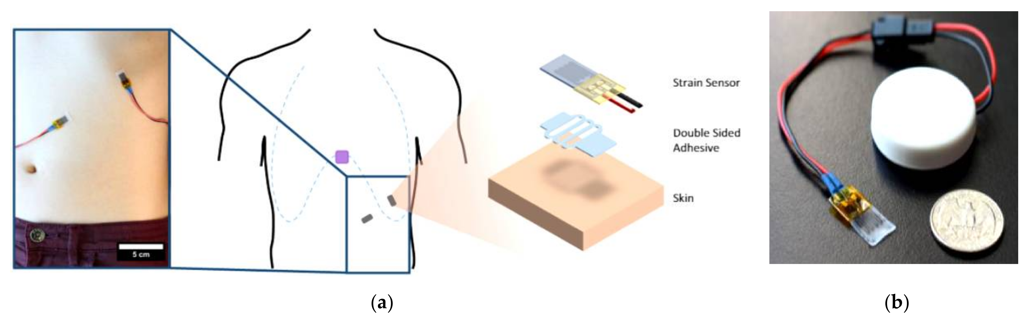
  62. Pegan, J.D.; Zhang, J.; Chu, M.; Nguyen, T.; Park, S.-J.; Paul, A.; Kim, J.; Bachman, M.; Khine, M. Skin-mountable stretch sensor for wearable health monitoring. Nanoscale 2016, 8, 17295–17303. [Google Scholar] [CrossRef]
  63. Konno, K.; Mead, J. Measurement of the separate volume changes of rib cage and abdomen during breathing. J. Appl. Physiol. 1967, 22, 407–422. [Google Scholar] [CrossRef]
  64. Marani, R.; Gelao, G.; Perri, A.G. A new system for continuous monitoring of breathing and kinetic activity. J. Sens. 2010, 2010, 434863. [Google Scholar] [CrossRef]
  65. Massaroni, C.; Di Tocco, J.; Lo Presti, D.; Longo, U.G.; Miccinilli, S.; Sterzi, S.; Formica, D.; Saccomandi, P.; Schena, E. Smart Textile based on piezoresistive sensing elements for respiratory monitoring. IEEE Sens. J. 2019, 19, 7718–7725. [Google Scholar] [CrossRef]
  66. Bauer, S.; Bauer-Gogonea, S.; Graz, I.; Kaltenbrunner, M.; Keplinger, C.; Schwödiauer, R. 25th anniversary article: A soft future: From robots and sensor skin to energy harvesters. Adv. Mater. 2014, 26, 149–162. [Google Scholar] [CrossRef] [Green Version]
  67. Zhang, C.; Zhang, J.; Chen, D.; Meng, X.; Liu, L.; Wang, K.; Jiao, Z.; Sun, T.; Wang, D.; Niu, S.; et al. Crack-based and hair-like sensors inspired from arthropods: A review. J. Bionic Eng. 2020, 17, 867–898. [Google Scholar] [CrossRef]
  68. De Fazio, R.; Cafagna, D.; Marcuccio, G.; Minerba, A.; Visconti, P. A multi-source harvesting system applied to sensor-based smart garments for monitoring workers’ bio-physical parameters in harsh environments. Energies 2020, 13, 2161. [Google Scholar] [CrossRef]
  69. Gaetani, F.; Primiceri, P.; Antonio Zappatore, G.; Visconti, P. Hardware design and software development of a motion control and driving system for transradial prosthesis based on a wireless myoelectric armband. IET Sci. Meas. Technol. 2019, 13, 354–362. [Google Scholar] [CrossRef]
  70. Visconti, P.; de Fazio, R.; Costantini, P.; Miccoli, S.; Cafagna, D. Innovative complete solution for health safety of children unintentionally forgotten in a car: A smart arduino-based system with user app for remote control. IET Sci. Meas. Technol. 2020, 14, 665–675. [Google Scholar] [CrossRef]
  71. Tang, Y.; Zhao, Z.; Hu, H.; Liu, Y.; Wang, X.; Zhou, S.; Qiu, J. Highly stretchable and ultrasensitive strain sensor based on reduced graphene oxide microtubes–elastomer composite. ACS Appl. Mater. Interfaces 2015, 7, 27432–27439. [Google Scholar] [CrossRef]
  72. Pang, C.; Lee, G.-Y.; Kim, T.; Kim, S.M.; Kim, H.N.; Ahn, S.-H.; Suh, K.-Y. A flexible and highly sensitive strain-gauge sensor using reversible interlocking of nanofibres. Nat. Mater. 2012, 11, 795–801. [Google Scholar] [CrossRef] [PubMed]
  73. Wang, C.; Li, X.; Gao, E.; Jian, M.; Xia, K.; Wang, Q.; Xu, Z.; Ren, T.; Zhang, Y. Carbonized silk fabric for ultrastretchable, highly sensitive, and wearable strain sensors. Adv. Mater. 2016, 28, 6640–6648. [Google Scholar] [CrossRef] [PubMed]
  74. Esfahani, M.I.M. Chapter 6—Smart textiles in healthcare: A summary of history, types, applications, challenges, and future trends. In Nanosensors and Nanodevices for Smart Multifunctional Textiles; Ehrmann, A., Nguyen, T.A., Nguyen Tri, P., Eds.; Micro and Nano Technologies; Elsevier: Amsterdam, The Netherlands, 2021; pp. 93–107. ISBN 978-0-12-820777-2. [Google Scholar]
  75. Angelucci, A.; Cavicchioli, M.; Cintorrino, I.A.; Lauricella, G.; Rossi, C.; Strati, S.; Aliverti, A. Smart textiles and sensorized garments for physiological monitoring: A review of available solutions and techniques. Sensors 2021, 21, 814. [Google Scholar] [CrossRef] [PubMed]
  76. Amjadi, M.; Pichitpajongkit, A.; Lee, S.; Ryu, S.; Park, I. Highly stretchable and sensitive strain sensor based on silver nanowire–elastomer nanocomposite. ACS Nano 2014, 8, 5154–5163. [Google Scholar] [CrossRef] [PubMed]
  77. Hwang, B.-U.; Lee, J.-H.; Trung, T.Q.; Roh, E.; Kim, D.-I.; Kim, S.-W.; Lee, N.-E. Transparent stretchable self-powered patchable sensor platform with ultrasensitive recognition of human activities. ACS Nano 2015, 9, 8801–8810. [Google Scholar] [CrossRef] [PubMed]
  78. Kim, J.; Lee, M.; Shim, H.J.; Ghaffari, R.; Cho, H.R.; Son, D.; Jung, Y.H.; Soh, M.; Choi, C.; Jung, S.; et al. Stretchable silicon nanoribbon electronics for skin prosthesis. Nat. Commun. 2014, 5, 5747. [Google Scholar] [CrossRef] [PubMed] [Green Version]
  79. Lu, N.; Lu, C.; Yang, S.; Rogers, J. Highly sensitive skin-mountable strain gauges based entirely on elastomers. Adv. Funct. Mater. 2012, 22, 4044–4050. [Google Scholar] [CrossRef]
  80. Park, J.; Lee, Y.; Hong, J.; Lee, Y.; Ha, M.; Jung, Y.; Lim, H.; Kim, S.Y.; Ko, H. Tactile-direction-sensitive and stretchable electronic skins based on human-skin-inspired interlocked microstructures. ACS Nano 2014, 8, 12020–12029. [Google Scholar] [CrossRef]
  81. Daňová, R.; Olejnik, R.; Slobodian, P.; Matyas, J. The piezoresistive highly elastic sensor based on carbon nanotubes for the detection of breath. Polymers 2020, 12, 713. [Google Scholar] [CrossRef] [Green Version]
  82. Tadakaluru, S.; Thongsuwan, W.; Singjai, P. Stretchable and flexible high-strain sensors made using carbon nanotubes and graphite films on natural rubber. Sensors 2014, 14, 868–876. [Google Scholar] [CrossRef] [Green Version]
  83. Hajjaj, A.Z.; Chappanda, K.N.; Batra, N.M.; Hafiz, M.A.A.; Costa, P.M.F.J.; Younis, M.I. Miniature pressure sensor based on suspended MWCNT. Sens. Actuators A Phys. 2019, 292, 11–16. [Google Scholar] [CrossRef]
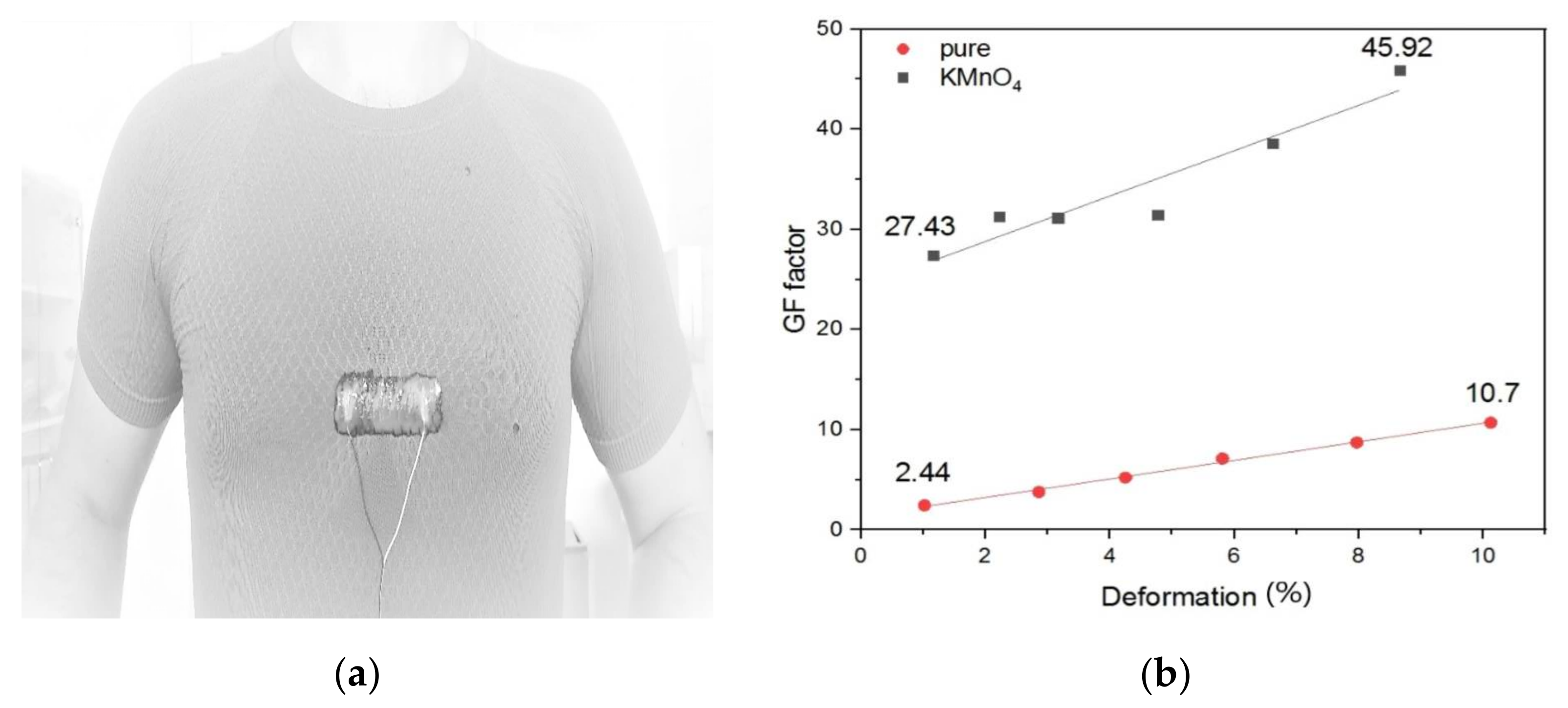
  84. Slobodian, P.; Riha, P.; Olejnik, R.; Cvelbar, U.; Saha, P. Enhancing effect of KMnO4 oxidation of carbon nanotubes network embedded in elastic polyurethane on overall electro-mechanical properties of composite. Compos. Sci. Technol. 2013, 81, 54–60. [Google Scholar] [CrossRef] [Green Version]
  85. Wang, L.; Zhang, F.; Lu, K.; Abdulaziz, M.; Li, C.; Zhang, C.; Chen, J.; Li, Y. Nano-copper enhanced flexible device for simultaneous measurement of human respiratory and electro-cardiac activities. J. Nanobiotechnol. 2020, 18, 1–15. [Google Scholar] [CrossRef]
  86. Mao, L.; Meng, Q.; Ahmad, A.; Wei, Z. Mechanical analyses and structural design requirements for flexible energy storage devices. Adv. Energy Mater. 2017, 7, 1700535. [Google Scholar] [CrossRef] [Green Version]
  87. Martinsson, E. Nanoplasmonic Sensing Using Metal Nanoparticles; Department of Physics, Chemistry and Biology, Molecular Physics, Linköping University; Linköping University Electronic Press: Linköping, Sweden, 2014; ISBN 978-91-7519-223-9. [Google Scholar]
  88. Zahn, M.; Pao, S.-C. Effects of step changes in excitation from a steady state on the transient electric field and space charge behavior for unipolar ion conduction: I. Step changes in current. J. Electrost. 1975, 1, 235–248. [Google Scholar] [CrossRef]
  89. Wei, Y.; Chen, S.; Lin, Y.; Yuan, X.; Liu, L. Silver nanowires coated on cotton for flexible pressure sensors. J. Mater. Chem. C 2016, 4, 935–943. [Google Scholar] [CrossRef]
  90. Zhou, R.; Li, P.; Fan, Z.; Du, D.; Ouyang, J. Stretchable heaters with composites of an intrinsically conductive polymer, reduced graphene oxide and an elastomer for wearable thermotherapy. J. Mater. Chem. C 2017, 5, 1544–1551. [Google Scholar] [CrossRef] [Green Version]
  91. Luo, J.; Lu, H.; Zhang, Q.; Yao, Y.; Chen, M.; Li, Q. Flexible carbon nanotube/polyurethane electrothermal films. Carbon 2016, 110, 343–349. [Google Scholar] [CrossRef] [Green Version]
  92. Pang, Y.; Tian, H.; Tao, L.; Li, Y.; Wang, X.; Deng, N.; Yang, Y.; Ren, T.-L. Flexible, highly sensitive, and wearable pressure and strain sensors with graphene porous network structure. ACS Appl. Mater. Interfaces 2016, 8, 26458–26462. [Google Scholar] [CrossRef]
  93. Ma, Y.; Liu, N.; Li, L.; Hu, X.; Zou, Z.; Wang, J.; Luo, S.; Gao, Y. A highly flexible and sensitive piezoresistive sensor based on mxene with greatly changed interlayer distances. Nat. Commun. 2017, 8, 1207. [Google Scholar] [CrossRef] [Green Version]
  94. Lu, Y.; Tian, M.; Sun, X.; Pan, N.; Chen, F.; Zhu, S.; Zhang, X.; Chen, S. Highly sensitive wearable 3D piezoresistive pressure sensors based on graphene coated isotropic non-woven substrate. Compos. Part A Appl. Sci. Manuf. 2019, 117, 202–210. [Google Scholar] [CrossRef]
  95. Tannarana, M.; Solanki, G.K.; Bhakhar, S.A.; Patel, K.D.; Pathak, V.M.; Pataniya, P.M. 2D-SnSe 2 nanosheet functionalized piezo-resistive flexible sensor for pressure and human breath monitoring. ACS Sustain. Chem. Eng. 2020, 8, 7741–7749. [Google Scholar] [CrossRef]
  96. Lian, Y.; Yu, H.; Wang, M.; Yang, X.; Zhang, H. Ultrasensitive wearable pressure sensors based on silver nanowire-coated fabrics. Nanoscale Res. Lett. 2020, 15, 70. [Google Scholar] [CrossRef]
  97. Pacelli, M.; Caldani, L.; Paradiso, R. Textile piezoresistive sensors for biomechanical variables monitoring. In Proceedings of the 2006 International Conference of the IEEE Engineering in Medicine and Biology Society, New York, NY, USA, 30 August–3 September 2006; IEEE: New York, NY, USA, 2006; pp. 5358–5361. [Google Scholar]
  98. Jang, S.; Choi, J.Y.; Yoo, E.S.; Lim, D.Y.; Lee, J.Y.; Kim, J.K.; Pang, C. Printable wet-resistive textile strain sensors using bead-blended composite ink for robustly integrative wearable electronics. Compos. Part B Eng. 2021, 210, 108674. [Google Scholar] [CrossRef]
  99. Tamura, T. Wearable inertial sensors and their applications. In Wearable Sensors; Sazonov, E., Neuman, M.R., Eds.; Academic Press: Oxford, UK, 2014; pp. 85–104. ISBN 978-0-12-418662-0. [Google Scholar]
  100. Rahmani, M.H.; Berkvens, R.; Weyn, M. Chest-worn inertial sensors: A survey of applications and methods. Sensors 2021, 21, 2875. [Google Scholar] [CrossRef]
  101. Gaidhani, A.; Moon, K.S.; Ozturk, Y.; Lee, S.Q.; Youm, W. Extraction and analysis of respiratory motion using wearable inertial sensor system during trunk motion. Sensors 2017, 17, 2932. [Google Scholar] [CrossRef] [Green Version]
  102. Gjoreski, H.; Lustrek, M.; Gams, M. Accelerometer placement for posture recognition and fall detection. In Proceedings of the 2011 Seventh International Conference on Intelligent Environments, Nottingham, UK, 25–28 July 2011; IEEE: Nottingham, UK, 2011; pp. 47–54. [Google Scholar]
  103. Da Costa, T.D.; Vara, M.D.F.F.; Cristino, C.S.; Zanella, T.Z.; Neto, G.N.N.; Nohama, P. Breathing Monitoring and Pattern Recognition with Wearable Sensors; IntechOpen: London, UK, 2019; ISBN 978-1-78984-497-9. [Google Scholar]
  104. Phan, D.H.; Bonnet, S.; Guillemaud, R.; Castelli, E.; Pham Thi, N.Y. Estimation of respiratory waveform and heart rate using an accelerometer. In Proceedings of the 2008 30th Annual International Conference of the IEEE Engineering in Medicine and Biology Society, Vancouver, BC, Canada, 20–25 August 2008; pp. 4916–4919. [Google Scholar]
  105. Chan, A.M.; Ferdosi, N.; Narasimhan, R. Ambulatory respiratory rate detection using ecg and a triaxial accelerometer. In Proceedings of the 2013 35th Annual International Conference of the IEEE Engineering in Medicine and Biology Society (EMBC), Osaka, Japan, 3–7 July 2013; Volume 2013, pp. 4058–4061. [Google Scholar] [CrossRef]
  106. Elfaramawy, T.; Fall, C.L.; Arab, S.; Morissette, M.; Lellouche, F.; Gosselin, B. A wireless respiratory monitoring system using a wearable patch sensor network. IEEE Sens. J. 2019, 19, 650–657. [Google Scholar] [CrossRef]
  107. Cleland, I.; Kikhia, B.; Nugent, C.; Boytsov, A.; Hallberg, J.; Synnes, K.; McClean, S.; Finlay, D. Optimal placement of accelerometers for the detection of everyday activities. Sensors 2013, 13, 9183–9200. [Google Scholar] [CrossRef] [PubMed] [Green Version]
  108. Preejith, S.P.; Jeelani, A.; Maniyar, P.; Joseph, J.; Sivaprakasam, M. Accelerometer based system for continuous respiratory rate monitoring. In Proceedings of the 2017 IEEE International Symposium on Medical Measurements and Applications (MeMeA), Rochester, MN, USA, 7–10 May 2017; pp. 171–176. [Google Scholar]
  109. Shabeeb, A.G.; Al-Askery, A.J.; Humadi, A.F. Design and implementation of breathing rate measurement systembased on accelerometer sensor. IOP Conf. Ser. Mater. Sci. Eng. 2020, 745, 012100. [Google Scholar] [CrossRef]
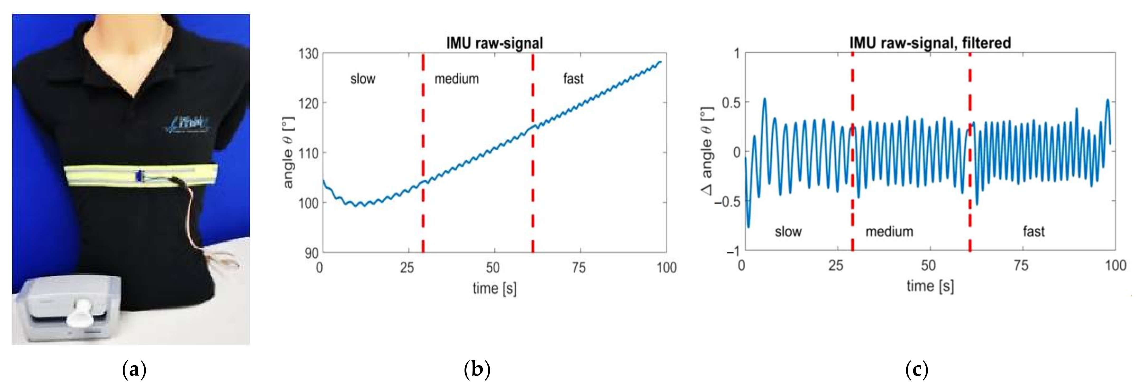
  110. Beck, S.; Laufer, B.; Krueger-Ziolek, S.; Moeller, K. Measurement of respiratory rate with inertial measurement units. Curr. Dir. Biomed. Eng. 2020, 6, 237–240. [Google Scholar] [CrossRef]
  111. Cesareo, A.; Nido, S.A.; Biffi, E.; Gandossini, S.; D’Angelo, M.G.; Aliverti, A. A wearable device for breathing frequency monitoring: A pilot study on patients with muscular dystrophy. Sensors 2020, 20, 5346. [Google Scholar] [CrossRef]
  112. Fekr, A.R.; Janidarmian, M.; Radecka, K.; Zilic, Z. A medical cloud-based platform for respiration rate measurement and hierarchical classification of breath disorders. Sensors 2014, 14, 11204–11224. [Google Scholar] [CrossRef]
  113. Ruminski, J.; Bujnowski, A.; Czuszynski, K.; Kocejko, T. Estimation of respiration rate using an accelerometer and thermal camera in EGlasses. In Proceedings of the 2016 Federated Conference on Computer Science and Information Systems (FedCSIS), Gdansk, Poland, 11–14 September 2016; pp. 1431–1434. [Google Scholar]
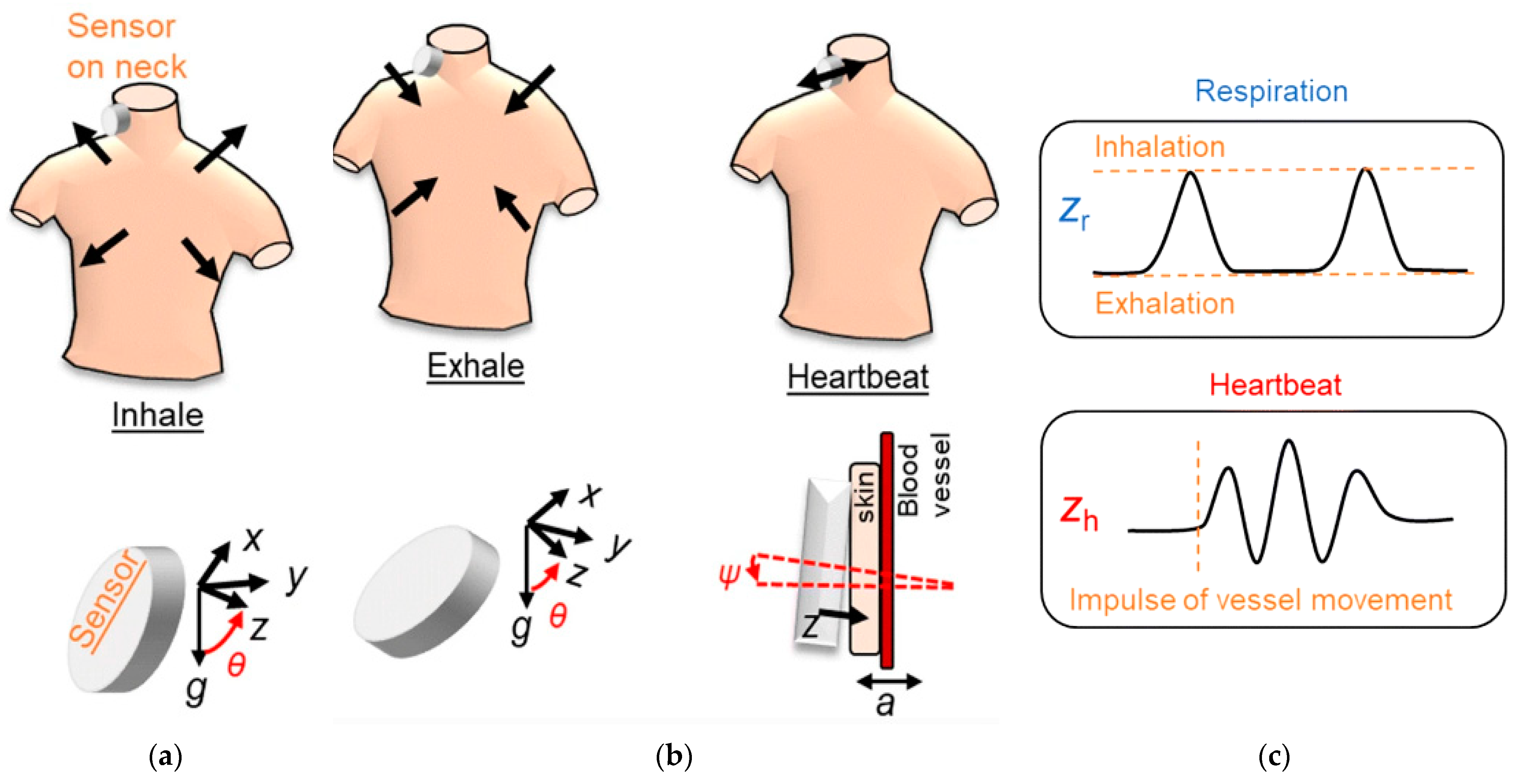
  114. Kano, S.; Mekaru, H. Preliminary comparison of respiratory signals using acceleration on neck and humidity in exhaled air. Microsyst. Technol. 2021, 27, 1–9. [Google Scholar] [CrossRef]
  115. Manoni, A.; Loreti, F.; Radicioni, V.; Pellegrino, D.; Della Torre, L.; Gumiero, A.; Halicki, D.; Palange, P.; Irrera, F. A new wearable system for home sleep apnea testing, screening, and classification. Sensors 2020, 20, 7014. [Google Scholar] [CrossRef]
  116. Röddiger, T.; Wolffram, D.; Laubenstein, D.; Budde, M.; Beigl, M. Towards respiration rate monitoring using an in-ear headphone inertial measurement unit. In Proceedings of the 1st International Workshop on Earable Computing; Association for Computing Machinery, New York, NY, USA, 21–26 September 2019; pp. 48–53. [Google Scholar]
  117. Jayarathna, T.; Gargiulo, G.D.; Breen, P.P. Continuous vital monitoring during sleep and light activity using carbon-black elastomer sensors. Sensors 2020, 20, 1583. [Google Scholar] [CrossRef] [Green Version]
  118. Cheng, Y.; Wang, K.; Xu, H.; Li, T.; Jin, Q.; Cui, D. Recent developments in sensors for wearable device applications. Anal. Bioanal. Chem. 2021. [Google Scholar] [CrossRef]
  119. Shen, C.-L.; Huang, T.-H.; Hsu, P.-C.; Ko, Y.-C.; Chen, F.-L.; Wang, W.-C.; Kao, T.; Chan, C.-T. Respiratory rate estimation by using ecg, impedance, and motion sensing in smart clothing. J. Med. Biol. Eng. 2017, 37, 826–842. [Google Scholar] [CrossRef]
  120. Fedotov, A.A.; Akulov, S.A.; Akulova, A.S. Motion artifacts reduction in wearable respiratory monitoring device. In EMBEC & NBC 2017; Eskola, H., Väisänen, O., Viik, J., Hyttinen, J., Eds.; Springer: Singapore, 2018; pp. 1121–1124. [Google Scholar]
  121. Nabavi, S.; Bhadra, S. A robust fusion method for motion artifacts reduction in photoplethysmography signal. IEEE Trans. Instrum. Meas. 2020, 69, 9599–9608. [Google Scholar] [CrossRef]
  122. Lepine, N.N.; Tajima, T.; Ogasawara, T.; Kasahara, R.; Koizumi, H. Robust respiration rate estimation using adaptive kalman filtering with textile ecg sensor and accelerometer. In Proceedings of the 38th Annual International Conference of the IEEE Engineering in Medicine and Biology Society (EMBC), Orlando, FL, USA, 16–20 August 2016; Volume 2016, pp. 3797–3800. [Google Scholar] [CrossRef]
  123. Yoon, J.-W.; Noh, Y.-S.; Kwon, Y.-S.; Kim, W.-K.; Yoon, H.-R. Improvement of dynamic respiration monitoring through sensor fusion of accelerometer and gyro-sensor. J. Electr. Eng. Technol. 2014, 9, 334–343. [Google Scholar] [CrossRef] [Green Version]
  124. Vanegas, E.; Igual, R.; Plaza, I. Sensing systems for respiration monitoring: A technical systematic review. Sensors 2020, 20, 5446. [Google Scholar] [CrossRef]
  125. Huang, C.-C.; Lin, W.-Y.; Lee, M.-Y. Development and verification of an accelerometer-based respiratory detection algorithm with wearable instrumented smart clothes. In Proceedings of the 2017 IEEE International Conference on Systems, Man, and Cybernetics (SMC), Banff, AB, Canada, 5–8 October 2017; IEEE: Banff, AB, Canada, 2017; pp. 578–581. [Google Scholar]
  126. Antony Raj, A.; Preejith, S.P.; Raja, V.S.; Joseph, J.; Sivaprakasam, M. Clinical validation of a wearable respiratory rate device for neonatal monitoring. In Proceedings of the 40th Annual International Conference of the IEEE Engineering in Medicine and Biology Society (EMBC), Honolulu, HI, USA, 18–21 July 2018; IEEE: Honolulu, HI, USA, 2018; pp. 1628–1631. [Google Scholar]
  127. Doheny, E.P.; Lowery, M.M.; Russell, A.; Ryan, S. Estimation of respiration rate and sleeping position using a wearable accelerometer. In Proceedings of the 2020 42nd Annual International Conference of the IEEE Engineering in Medicine Biology Society (EMBC), Montral, QC, Canada, 20–24 July 2020; IEEE: Montral, QC, Canada, 2020; pp. 4668–4671. [Google Scholar]
  128. Fekr, A.R.; Radecka, K.; Zilic, Z. Tidal volume variability and respiration rate estimation using a wearable accelerometer sensor. In Proceedings of the 2014 4th International Conference on Wireless Mobile Communication and Healthcare—Transforming Healthcare Through Innovations in Mobile and Wireless Technologies (MOBIHEALTH), Athens, Greece, 3–5 November 2014; pp. 1–6. [Google Scholar]
  129. Dan, G.; Zhao, J.; Chen, Z.; Yang, H.; Zhu, Z. A novel signal acquisition system for wearable respiratory monitoring. IEEE Access 2018, 6, 34365–34371. [Google Scholar] [CrossRef]
  130. Sun, X.; Qiu, L.; Wu, Y.; Tang, Y.; Cao, G. SleepMonitor: Monitoring respiratory rate and body position during sleep using smartwatch. In Proceedings of the ACM on Interactive, Mobile, Wearable and Ubiquitous Technologies, New York, NY, USA, 11 September 2017; Volume 1, pp. 1–22. [Google Scholar] [CrossRef]
  131. Jafari Tadi, M.; Koivisto, T.; Pänkäälä, M.; Paasio, A. Accelerometer-based method for extracting respiratory and cardiac gating information for dual gating during nuclear medicine imaging. Int. J. Biomed. Imaging 2014, 2014, 690124. [Google Scholar] [CrossRef]
  132. Madhav, K.V.; Ram, M.R.; Krishna, E.H.; Reddy, K.N.; Reddy, K.A. Estimation of respiratory rate from principal components of photoplethysmographic signals. In Proceedings of the 2010 IEEE EMBS Conference on Biomedical Engineering and Sciences (IECBES), Kuala Lumpur, Malaysia, 30 November–2 December 2010; IEEE: Kuala Lumpur, Malaysia, 2010; pp. 311–314. [Google Scholar]
  133. Jin, A.; Yin, B.; Morren, G.; Duric, H.; Aarts, R.M. Performance evaluation of a tri-axial accelerometry-based respiration monitoring for ambient assisted living. In Proceedings of the 2009 Annual International Conference of the IEEE Engineering in Medicine and Biology Society, Minneapolis, MI, USA, 3–6 September 2009; pp. 5677–5680. [Google Scholar]
  134. Liu, G.-Z.; Wu, D.; Mei, Z.; Zhu, Q.; Wang, L. Automatic detection of respiratory rate from electrocardiogram, respiration induced plethysmography and 3d acceleration signals. J. Cent. South Univ. 2013, 20, 2423–2431. [Google Scholar] [CrossRef]
  135. Jarchi, D.; Rodgers, S.J.; Tarassenko, L.; Clifton, D. Accelerometry-based estimation of respiratory rate for post-intensive care patient monitoring. IEEE Sens. J. 2018, 18, 4981–4989. [Google Scholar] [CrossRef] [Green Version]
  136. Warnecke, J.M.; Wang, J.; Deserno, T.M. Noise reduction for efficient in-vehicle respiration monitoring with accelerometers. In Proceedings of the 2019 41st Annual International Conference of the IEEE Engineering in Medicine and Biology Society (EMBC), Berlin, Germany, 23–27 July 2019; IEEE: Berlin, Germany, 2019; pp. 3257–3261. [Google Scholar]
  137. Alafeef, M.; Fraiwan, M. Smartphone-based respiratory rate estimation using photoplethysmographic imaging and discrete wavelet transform. J Ambient Intell. Hum. Comput. 2020, 11, 693–703. [Google Scholar] [CrossRef]
  138. Jiang, P.; Zhu, R. Dual tri-axis accelerometers for monitoring physiological parameters of human body in sleep. In Proceedings of the 2016 IEEE Sensors, Orlando, FL, USA, 30 October–3 November 2016; IEEE: Orlando, FL, USA, 2016; pp. 1–3. [Google Scholar]
  139. Cesareo, A.; Previtali, Y.; Biffi, E.; Aliverti, A. Assessment of breathing parameters using an inertial measurement unit (imu)-based system. Sensors 2019, 19, 88. [Google Scholar] [CrossRef] [Green Version]
  140. Lee, J.; Yoo, S.K. Respiration rate estimation based on independent component analysis of accelerometer data: Pilot single-arm intervention study. JMIR Mhealth Uhealth 2020, 8. [Google Scholar] [CrossRef] [PubMed]
  141. Skowronski, M.D.; Shrivastav, R.; Hunter, E.J. Cepstral peak sensitivity: A theoretic analysis and comparison of several implementations. J. Voice 2015, 29, 670–681. [Google Scholar] [CrossRef] [PubMed] [Green Version]
  142. Johnson, A.E.W.; Cholleti, S.R.; Buchman, T.G.; Clifford, G.D. Improved respiration rate estimation using a kalman filter and wavelet cross-coherence. In Proceedings of the Computing in Cardiology 2013, Zaragoza, Spain, 22–25 September 2013; IEEE: Zaragoza, Spain, 2013; pp. 791–794. [Google Scholar]
  143. Wang, S.; Liu, M.; Pang, B.; Li, P.; Yao, Z.; Zhang, X.; Chen, H. A new physiological signal acquisition patch designed with advanced respiration monitoring algorithm based on 3-axis accelerator and gyroscope. In Proceedings of the 2018 40th Annual International Conference of the IEEE Engineering in Medicine and Biology Society (EMBC), Honolulu, HI, USA, 18–21 July 2018; IEEE: Honolulu, HI, USA, 2018; pp. 441–444. [Google Scholar]
  144. Hadiyoso, S.; Dewi, E.M.; Mengko, T.L.E.R.; Zakaria, H. Respiratory rate extraction based on plethysmographic wave analysis. IOP Conf. Ser. Mater. Sci. Eng. 2020, 830, 032050. [Google Scholar] [CrossRef]
  145. Mabrouk, M.; Rajan, S.; Bolic, M.; Forouzanfar, M.; Dajani, H.R.; Batkin, I. Human breathing rate estimation from radar returns using harmonically related filters. J. Sens. 2016, 2016, 9891852. [Google Scholar] [CrossRef]
  146. Gomes, N.; Iranfar, S.; Maksymenko, K.; Aridhi, S.; Guyon, A. Physiological effects (Heart Rate, Respiration Rate and EEG) of rapid relaxation devices with sensorial immersion: A pilot study. J. Interdiscip. Methodol. Issues Sci. 2020, 9. [Google Scholar] [CrossRef]
  147. El-Sheimy, N.; Youssef, A. Inertial sensors technologies for navigation applications: State of the art and future trends. Satell. Navig. 2020, 1, 2. [Google Scholar] [CrossRef] [Green Version]
  148. Rast, F.M.; Labruyère, R. Systematic review on the application of wearable inertial sensors to quantify everyday life motor activity in people with mobility impairments. J. Neuroeng. Rehabil. 2020, 17, 148. [Google Scholar] [CrossRef]
  149. Karacocuk, G.; Höflinger, F.; Zhang, R.; Reindl, L.M.; Laufer, B.; Möller, K.; Röell, M.; Zdzieblik, D. Inertial sensor-based respiration analysis. IEEE Trans. Instrum. Meas. 2019, 68, 4268–4275. [Google Scholar] [CrossRef]
  150. Balestrieri, E.; Boldi, F.; Colavita, A.R.; de Vito, L.; Laudato, G.; Oliveto, R.; Picariello, F.; Rivaldi, S.; Scalabrino, S.; Torchitti, P.; et al. The architecture of an innovative smart t-shirt based on the internet of medical things paradigm. In Proceedings of the 2019 IEEE International Symposium on Medical Measurements and Applications (MeMeA), Istanbul, Turkey, 26–28 June 2019; pp. 1–6. [Google Scholar]
Figure 1. Prototype of the wearable device for RR monitoring proposed in [50] (a); waveforms acquired by the device: original data (red curve), shifted data (blue curve), and the zero axis (dotted line) (b); prototype of the sensing system mounted (c).
Electronics 10 02178 g001
Figure 2. Prototype of the device discussed in [52] (a) and schematic representation of the piezoresistive sensor (b). Output signal includes both pulse wave and respiration component (left) and after being filtered by a 100 Hz high-pass for extracting the breathing component (right) (c).
Electronics 10 02178 g002
Figure 3. KTC’s circuit diagram scheme (a); KTC respiration system prototype (b) [53].
Electronics 10 02178 g003
Figure 4. LCP flow sensor proposed in [55] (a); a 3D printed housing was developed to package the sensor in the flow generator tube (b). Experimental setup used to test LCP flow sensor, where this last is connected to the flow generator, filter/amplifier, and data acquisition devices (c) [55].
Electronics 10 02178 g004
Figure 5. Strain sensors placed on the ribcage and abdomen (a); developed sensing unit equipped with a strain sensor (b) [61].
Electronics 10 02178 g005
Figure 6. Gauge factor for MWCNTs (pure) and oxidized MWCNTs (KMnO4) sensors as deformation increases (a); sensor with PU/oxidized MWCNTs applied to a commercial T-shirt (b) [81].
Electronics 10 02178 g006
Figure 7. IMU-belt proposed in [110] with the reference spirometer (a); IMU-signal raw (b), and filtered (c) data.
Electronics 10 02178 g007
Figure 8. Change of accelerometer axis values during inhalation and exhalation, and position of the axis with respect to the sensor’s surface (a); the pulse of the heartbeat generates an acceleration that can be evaluated even if small (b); examples of respiratory and cardiac signals (c) [114].
Electronics 10 02178 g008
Figure 9. The external case of the MORFEA device (a), with the accelerometer and PPG sensors on one side (b), and the Bluetooth module on the other (c) [115].
Electronics 10 02178 g009
Figure 10. Schematic representation of the hardware setup employed for the tests [61].
Electronics 10 02178 g010
Figure 11. Structure of the VitalCore wearable device with highlighted the main components [117].
Electronics 10 02178 g011
Figure 12. Visual interpretation of the algorithms to identify movements during sleep [117].
Electronics 10 02178 g012
Figure 13. Flowchart of the algorithm to identify the starting points of inhalation and exhalation from the intersection of the respiration signal with the time axis [129].
Electronics 10 02178 g013
Figure 14. Schematization of the algorithm proposed in [115] for detecting apneas.
Electronics 10 02178 g014
Figure 15. Block diagrams of the algorithm for determining the RR from accelerometry [135].
Electronics 10 02178 g015
Table 1. Table with summarized the main wearable technologies used to detect the respiration rate.
Sensor TypeAdvantagesLimitations
Acoustic SensorPortable, cheap, and easy-to-use.Optimal sensor position should be determined. Background acoustic noise and movement artefacts must be deleted. In some settings, they are not usable.
Humidity SensorLess affected by the environmental conditions than pressure, flow, temperature sensorsNot suitable for long-time usage as it is uncomfortable. It needs some improvements to be commercialized.
Oximeter SensorVersatile, Simple, NoninvasiveThere are no particular disadvantages with this kind of sensor.
CO2 SensorHigh Sensitivity, Wide Linearity range
High Accuracy
Body movements seriously impact their performance.
Affected by the environmental conditions
ECG SensorVersatile, SimpleRequire the application of electrodes
Accelerometer SensorWide spectral range
Small dimensions
The sensitivity can be adjusted to detect from gross movements to small artery pulsation.
The sensor’s position is crucial.
Body movements seriously impact their performance.
Unwanted artefacts can affect the detected signal.
Textile SensorSimple integration into smart clothes or wearable devices.This kind of sensor is affected by movement artefacts.
Capacitive SensorHigh resolution, Low cost, Vibration-immunity and Low power consumptionThis kind of sensor is affected by movement artefacts.
Table 2. Table summarizing the discussed piezoresistive RR sensors from the point of view of the used sensing device, processing unit, sampling rate, availability of wireless communication, and wearability.
WorkSensing DeviceProcessing UnitSampling Frequency [Hz]Availability of Wireless CommunicationWearability
E. Venegas et al. [50]A201 FlexiForce sensorArduino Pro Mini (ATMega32U)50Bluetooth (HC-05)Medium
U. Saha et al. [51]PDMS/Graphene sensorArduino Uno (ATMega328p)1000WiFi (ESP8266)Low
T.V. Nguyen et al. [52]MEMS pressure sensorDL850 Acquisition board/PC1000NoHigh
R. K. Raji et al. [53]piezoresistive fabricSTM32F401RCT61000BLE (HC-08)Medium
B. Abbasnejad et al. [55]MEMS LCP pressure sensorNI-USB6003 board/PC2000NoLow
M. Chu et al. [61]Strain sensorNI-USB6003 board/PC1000BluetoothHigh
C. Massironi et al. [65]Silver conductive yarnsPIC18F46J5060Bluetooth (SPBT2632C2A)Medium
Table 3. Table with summarized the scientific works previously discussed from the point of view of the used substrate and sensing material, operative range, sensitivity and applications.
WorkSubstrateSensitive MaterialOperative RangeSensitivityCost
R. Danovà et al. [81]TPUMWCNTs oxidated by KMnO40.167 ÷ 1.066 MPa1.197 MPa−1
2–5 (GF)
Low
L. Wang et al. [85]PDMScarbon fiber enriched with nano-copper NPs0.1 ÷ 0.6 kPa0.053 ± 0.00079 kPa−1
0.98 (GF)
Medium
Y. Lu et al. [94]3D non-woven PET fabricrGO0 ÷ 30 kPa35.37 kPa−1Low
M. Tannarana et al. [95]Paper2D-SnSe2 nanosheets2 ÷ 25 kPa1.79 kPa−1Low
Y. Lian et al. [96]cotton fabricsAg nanowire0 ÷ 10 kPa3.24 × 105 kPa−1Medium
S. Jang et al. [98]PDMScarbon-based ink0 ÷ 2 MPa57 (GF)Medium
Table 4. Table with summarized the scientific works above discussed from the point of view of the number of used IMUs, processing unit, application area, availability of wireless communication and wearability.
WorkNumber of Used IMUsProcessing UnitApplication AreaAvailability of Wireless
Communication
Wearability
T. Elfaramawy et al. [78]2MSP-EXP430F5529LPChest
Abdomen
RF 2.4 GHzHigh
S. P. Preejith et al. [108]1
(MMA8451)
ARM Cortex M0 microcontrollerAbdomenBLEMedium
A. Shabeeb et al. [109]1
(ADXL345)
Arduino UNO
(ATmega 328p)
ChestNoMedium
S. Beck et al. [110]2
(MPU-6050)
Arduino MKR1010
(SAMD21)
ChestNoMedium
J. Ruminski et al. [113]1
(MPU-6500)
OMAP 4460Nasal septumBluetooth
WiFi
High
S. Kano et al. [114]2
(BM1160)
ARM Cortex M4 microcontrollerNeckBluetoothHigh
A. Cesareo et al. [111]3PCChest
Abdomen
BLEMedium
A. Manoni et al. [115]1
(LSM6DSM)
BlueNRG-1Nasal septumBLEHigh
A. R. Fekr et al. [112]1
(KXTJ9)
PCChestWiFiMedium
M. Chu et al. [61] 1
(ADXL326)
PCRibcage
Abdomen
BLEMedium
T. Röddiger et al. [116]1Smartphone/TabletAuricleBLEHigh
T. Jayarathna et al. [117]1
(LIS2DH)
CC2640R2FChestBLEHigh
Table 5. Comparative table of the scientific works related to innovative algorithms for monitoring the respiratory activity from the inertial data.
WorkNumber of Used of IMUsProcessing MethodsAdditional InformationPerformancesComplexity
C.-C. Huang et al. [125]1
(LSM6DS3)
Peak detectionNo95%Low
A. Raj [126]1
(LIS2HH12)
Peak detectionNo97.4%Low
E.P. Doheny et al. [127]1
(MC10)
Peak detectionPSG signal1.58 ± 0.54 BrPM 1Low
G. Dan et al. [129]1
(MPU6050)
Peak detectionCO2 analysis99.8%Low
A. Manoni et al. [115]1
(LSM6DSM)
PSD
PWA
PPG signal93%Medium
M. Jafari Tadi [131]1
(MMA8451Q)
FFT
Peak detection
SCG signal99.41 ÷ 99.81%Medium
G.-Z. Liu et al. [134]1Kalman filter
PCA
FFT
EDR signal
RIP signal
CO2 analysis
95.63%Medium
D. Jarchi et al. [135]1SSA
FFT
PPG signal2.56 BrPM 1High
J. Warnecke et al. [136]3
(Shimmer3)
PCA
FFT
ECG signal3.04 BrPM 1Medium
A. Cesareo et al. [139]1PCA
FFT
-2 BrPM 1Medium
J. Lee et al. [140]1ICA-0.47 BrPM 1Medium
S. Wang et al. [143]1Kalman filter
VCS
RIP signal1.58 ± 0.54 BrPM 1
(MAE)
High
1 Mean Absolute Error (MAE).
Publisher’s Note: MDPI stays neutral with regard to jurisdictional claims in published maps and institutional affiliations.

