Review

The Core of Medical Imaging: State of the Art and Perspectives on the Detectors

by
Maria Filomena Santarelli
1,2,
Giulio Giovannetti
1,2,
Valentina Hartwig
1,
Simona Celi
2,
Vincenzo Positano
2 and
Luigi Landini
3,*
1
CNR Institute of Clinical Physiology, 56124 Pisa, Italy
2
Fondazione Toscana “G. Monasterio”, 56124 Pisa, Italy
3
Dipartimento di Ingegneria dell’Informazione: DII, Pisa University, 56126 Pisa, Italy
*
Author to whom correspondence should be addressed.
Electronics 2021, 10(14), 1642; https://doi.org/10.3390/electronics10141642
Submission received: 3 June 2021 / Revised: 5 July 2021 / Accepted: 8 July 2021 / Published: 10 July 2021
(This article belongs to the Special Issue Digital Twin Technology: New Frontiers for Personalized Healthcare)

Abstract

:
In this review, the roles of detectors in various medical imaging techniques were described. Ultrasound, optical (near-infrared spectroscopy and optical coherence tomography) and thermal imaging, magnetic resonance imaging, computed tomography, single-photon emission tomography, positron emission tomography were the imaging modalities considered. For each methodology, the state of the art of detectors mainly used in the systems was described, emphasizing new technologies applied.

1. Introduction

Medical imaging is a constantly growing discipline, widely used both in clinical practice and in medical research. The ability to see and study, in vivo, anatomical areas of interest has always been an important feature of imaging systems for diagnostic purposes. Continuous technological development allows the creation of increasingly efficient tools with optimized spatial and temporal resolutions.
The various imaging systems exploit the interactions between the tissue of interest and the waves (mechanical or electromagnetic); from this interaction, the waves are modified/emitted and detected by appropriate sensors, obviously in different ways depending on the type and energy of the wave. Accordingly, in medical imaging, sensors can be considered as detection devices that sense the information coming from the interaction tissue-wave and transform the sensed information into an electrical signal or other information output. Their task is, therefore, very important for determining the quality of the resulting image.
This is why the detectors can be considered the core of the imaging device in which they are installed.
Obviously, according to the imaging methodology, these detectors have a different composition and are built according to different technologies.
In ultrasonic imaging, a transducer transforms electrical pulses into pressure waves that propagate into the tissue and, in receive mode, it converts the returning pressure waves into electrical signals.
Near-infrared spectroscopy (NIRS) systems require a source (i.e., laser) to generate light at a specific wavelength and a detector as receiving probe.
In infrared thermal (IRT) systems, an infrared camera detects the thermal radiation emitted by the body surface.
Optical coherence tomography (OCT) is a tomographic technique operating in the optical domain that involves a low-coherence light source.
Coils in magnetic resonance imaging (MRI) generate a radiofrequency magnetic field, which interacts with the tissue of interest and detects the field generated by the interaction itself.
In computed tomography (CT), the detectors detect X-rays crossing the patient’s body and transform them into an electric signal that is transmitted to a computer-based data processing system, able to reconstruct the tomographic view of the body.
Nuclear medicine imaging systems have gamma-ray detectors arranged in planes (gamma-cameras in single-photon emission computed tomography—SPECT) or circles around the patient (in positron emission tomography—PET), which receive gamma photons and transform them into an electrical signal.
The paper focuses on established medical image modalities currently used in the clinical setting; for each imaging method treated, this review shows the state of art and the future prospects of the sensors used.

2. Ultrasound Imaging

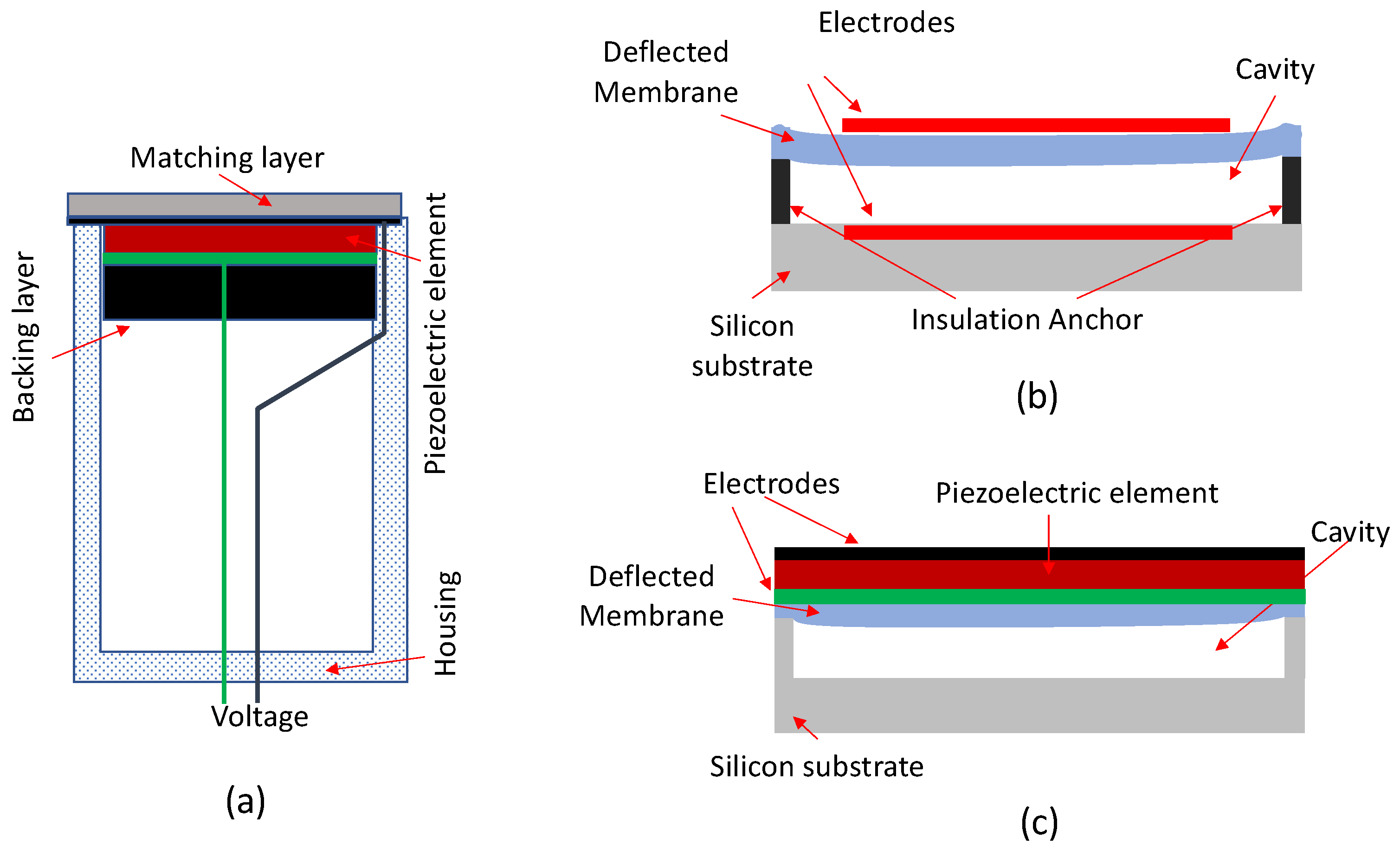
2.1. Piezoelectric Transducers Technology

Ultrasonic imaging is based on the pulse-echo technique in which a transducer transforms electrical pulses into pressure waves that propagate into the human body and, in receive mode, converts the return pressure waves into electrical signals. Its rapid expansion during the past few years was due to a rapid technological development that contributed to a dramatic improvement in image quality and diagnostic accuracy. Among the available technologies, piezoelectric transducers are the most diffuse and available in clinical ultrasound systems. Over time, continuous demand for improving non-optimal acoustic performances of piezoelectric ceramics, mainly lead zirconate titanate, produced various piezo composite materials by combining piezoceramic elements with a polymer. Among the advantages of these composites are broad bandwidth, multi-frequency, high resolution, good matching to human tissue, and high-density array transducers [1]. Such improvements have brought important benefits in various imaging applications. It is worth recalling that ultrasound super-resolution is an emerging technique proposed to visualize vascular tissue and atherosclerotic regions with a spatial resolution beyond the acoustic diffraction limit [2,3]. Multi-frequency transducers have opened to superharmonic imaging to become a reality thanks to the possibility to receive signal from the nonlinear response of microbubble at high-order harmonics using high-frequency transducers [4].
Despite many medical applications, such as ultrasound elastometry [5], which could be better understood using 3D information, ultrasonic imaging is still based on two-dimensional image acquisition and processing. Going from 2D to 3D ultrasound imaging, a 2D matrix transducer is required, entailing fabrication and implementation problems [6]. This is the reason why 3D ultrasound imaging methods based on 2-D array probes are continuing to improve in terms of fabrication and processing [7,8], and synthetic aperture ultrasound imaging [9,10]. Recently, the combination of miniaturized phased-array transducers and minimally invasive robotic surgery instruments is a further challenge in array development; preliminary phantom measurements demonstrate the feasibility to provide intraoperative image guidance and tissue characterization during endoscopic procedures [11].
Beyond any doubt, the beamforming scheme (a signal processing technique used in ultrasound, RF and microwaves arrays to steer and focus beam in transmission and reception) represents the core of any clinical ultrasound system. Over decades, the evolution in the commercial ultrasound apparatus allowed it to offer high-quality images at a frame rate span above any other imaging technique [12]. Recently, exploiting artificial intelligence techniques, new solutions to adaptive beamforming are being proposed to lower reconstruction time and computational burden [13,14].

2.2. Micromachined Ultrasonic Transducers

In the ultrasound transducer field, other technologies, such as micromachined transducers and optical ultrasound detection technology, are under testing for medical applications. With the advent of microelectromechanical systems technology, capacitive (cMUTs) and piezoelectric (pMUTs) micromachined ultrasonic transducers have gradually emerged [15]. These new-generation transducers utilize the flextensional vibration of an array of micromembranes, respectively using electrostatic or piezoelectric actuation principle (Figure 1). Unlike piezoelectric transducers, which use the thickness motion of a plate made of a piezoelectric ceramic, pMUTs are based on the bending motion of a thin membrane coupled with a thin piezoelectric film. The pMUTs technology could take advantage of a well established semiconductor fabrication technique, with benefit in terms of a cost-effective production of high-performance 2D medical arrays. Although there is still much to discover about the application of pMUTs technology to echographic technique, recent studies describe significant advances towards the improvement of echo-pulse parameters for high density pMUT-based 2-D arrays [16].
cMUTs are considered to be the next generation of ultrasound transducers as compared to conventional piezoelectric transducers. They have the advantages of higher transducer density elements design for two-dimensional arrays, high electromechanical conversion efficiency, broadband response, and material transparency [17].
Recently, an intra-vascular ultrasound transducer (IVUS) with cMUTs technology was made available for clinical applications [18]. Preliminary experimental data on such devices seem promising, but at present a lack of in-vivo clinical data prevents it from allowing direct comparison with established intracoronary imaging devices.
The broadband ultrasonic response and the material transparence of cMUTs technology disclose new clinical horizons in photoacoustic imaging (PAI). We recall that PAI is a recent modality that allows the delivery of optical energy that is absorbed by tissue causing thermoelastic expansion. Such expansion produces ultrasound waves that are detected by the ultrasonic transducer to produce images of optical absorption from the investigated tissue. The spectral content of acoustic signals is distributed over a wide frequency range. PAI is an imaging modality which non-invasively measures the concentration of tissue chromophores (endogenous contrast) to monitor the course of a disease. Conventionally, the detection of emitted ultrasound is performed with a piezoelectric transducer [19]. Using piezoelectric array ultrasound transducers, PAI has been evaluated in preclinical and in clinical applications based on combined ultrasound and PA imaging [20]. Limitations on the maximum depth of optical penetration are bypassed in minimally invasive photoacoustic imaging by delivering excitation light through miniature fiber-optics probes to the target tissue [21]. The use of cMUTs technology would allow a more effective alignment of the optical and acoustic focal points and a frequency spectrum suitable for capturing the high-frequency photoacoustic response [22,23].

2.3. All-Optical Ultrasound Detection Technology

While the integration of acoustic and optical systems offers important advantages with potential for clinical applications, nevertheless, it faces challenging technological problems. Since the optical and acoustic sensors are off-axis in the same housing, the misalignment contributes to increasing heterogeneity and reduces the signal-to-noise ratio (SNR). Optical ultrasound represents advances in recent technologies on the use of photoacoustic techniques to perform ultrasound transmission and reception with light [24]. Such new technologies provide more effective ultrasound transmission and more sensitive and ultra-broadband ultrasound detection [25]. In all-optical systems, ultrasound waves are generated from an optically absorbing coating and sent to the target tissues for pulse-echo ultrasound imaging. Under the pulsed laser excitation, the coating absorbs optical energy and converts the energy to rapid temperature rise, which results in ultrasound generation. The optical detection principle exploits optical resonance, where physical perturbation caused by ultrasound is converted into optical interference and recorded with optical methods. Existing methods generally fall into two categories: refractometry and interferometry. Refractometry exploits the photoelastic principle according to which acoustic waves interacting with a medium induce mechanical stress in that medium and consequently a change in refractive index that is proportional to the mechanical pressure [26]. The method uses a laser beam to measure changes in intensity, deflection angle, or phase of the probe beam at an optical detector due to changes in the refractive index in response to acoustic waves propagation. Optical interferometry methods for sound detection exploit alteration of physical characteristics of light produced in a medium perturbed by the propagation of ultrasonic waves that can be measured by optical interferometry. A promising technique to measure optic interferometry is the Fabry–Perot interferometer for its high sensitivity and bandwidth [27]. It is based on a concave Fabry–Perot cavity placed at the distal end of an optical fiber, which is interrogated with a tunable continuous-wave laser. Based on a small number of studies, the all-optical technology seems suitable for minimally invasive applications [28].

3. Optical and Thermal Imaging

Optical imaging techniques require a light source, i.e., laser or light-emitting diodes (LED), and detectors to catch the reflected or transmitted light returning from the tissues. Optical imaging techniques are functional imaging and have good contrast at high spatial resolution but a limited penetration depth into tissue. For this reason, optical imaging is mainly used in medicine to image superficial parts of the human body, such as skin, eyes, or other accessible body parts such as teeth, mucus, colon, and also heart and vessels during surgery or by means of intravascular probes.
Thermal imaging or infrared thermography is a widespread imaging technique able to evaluate the thermal distribution of a body without any contact between the sensors and the body itself. In the biomedical field, thermal imaging permits recording, in a non-invasive way, the cutaneous temperature. The main medical applications of thermal imaging are the diagnosis of breast cancer, diabetes neuropathy, peripheral vascular disorders, dermatology, neonatal physiology, and also computational psychophysiology.

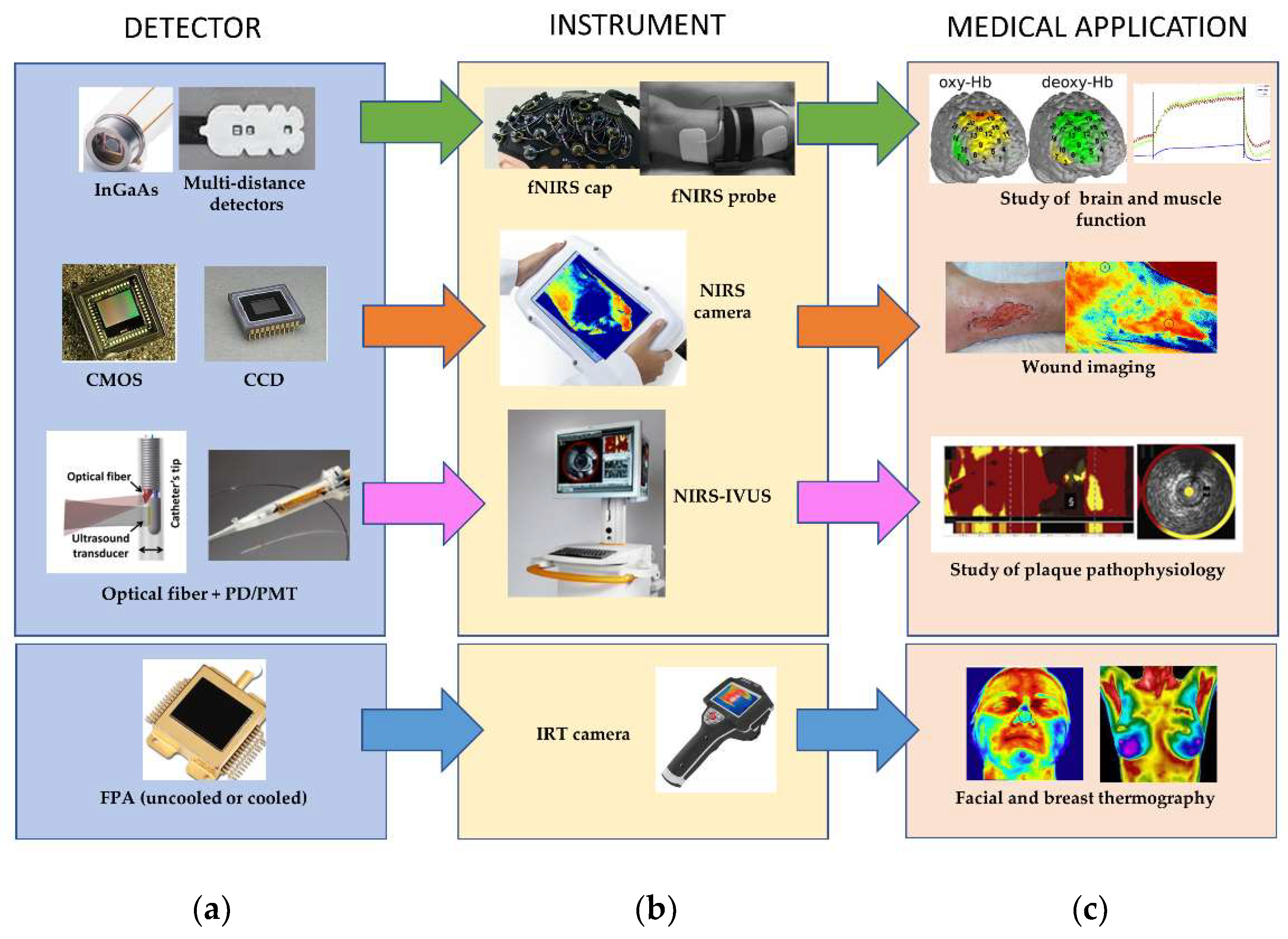
3.1. Near-Infrared Spectroscopy (NIRS)

Introduced by Jobsis in 1977 [29], near-infrared spectroscopy (NIRS) is a non-invasive optical technique that can measure changes in the hemoglobin oxygenation state in biological tissues. NIRS techniques are based on the propagation of infrared light through biological tissues. NIR light in the range of 700–1000 nm is mostly used because of its ability to penetrate the tissues up to a few centimeters.
In particular, NIRS is based on light absorbing molecules (chromophores) present in tissue and uses the absorption spectra of these substances to interpret the detected light levels as changes in chromophore concentrations. Photon propagation through the tissues depends on reflectance, scattering, and absorption effects related to the optical properties of the materials in the light path. In the NIRS range, the dominant chromophore of the biological tissue is hemoglobin: the hemoglobin light absorption varies with its oxygenation status, so it is possible to distinguish oxyhemoglobin (HbO2) and deoxyhemoglobin (Hb) contributors. Hb has its maximum absorption factor in the NIRS range at 780 nm, while HbO2 has the maximum absorption coefficient at 930 nm. Analyzing the reflected or transmitted light intensity, it is possible to determine the tissue oxygenation in various human tissues, including muscle, blood vessels, brain, and connective tissues.
NIRS techniques have several advantages [30], principally regarding the instrumentation, for example, the robustness of the measurement to motion artifacts which make it suitable for use on infants, small children, or psychiatric patients. The non-ionizing nature of the infrared light permits long-term monitoring, also at the bedside, given the portability of the instruments. NIRS techniques also have an excellent temporal sensitivity as well as reasonable spatial sensitivity; in contrast, functional magnetic resonance imaging (fMRI), positron emission tomography (PET), and single-photon emission computed tomography (SPECT) have a better spatial sensitivity but are weak in terms of temporal resolution.
To date, there are many medical applications of NIRS techniques [30], including monitoring of tissue oxygenation during muscle exercise, detecting tumors in the breast with a tomography technique [31], monitoring of the inflammatory process in rheumatoid arthritis disease, assessment of tissue perfusion, and peripheral microcirculation in healthy subjects [32,33] and scleroderma [34,35,36], monitoring of healing of venous leg ulcers [37], detection of brown adipose tissue activation [38], functional brain imaging for studies of neuro activation [39] in infants, small children or patients with epilepsy and brain mapping for neurosurgery (see Figure 2).

3.1.1. Instruments

All the commercially available NIRS instruments [40] require a source for the generation of light at a specific wavelength (generally a laser), a detector such as a photomultiplier tube (PMT) or a silicon photodiode, and finally, electronics for the two probes. Light can enter the tissue using continuous wave, frequency domain, or time-resolved mode [39]. The measurement can be obtained point-by-point or in imaging configuration: for a point measurement, only one source location and one or more detector locations are required, while to obtain an image each detector should be able to detect light from two or more source locations. Finally, several available instruments permit the measurements at more wavelengths to calculate the concentration changes for two chromophores simultaneously (Figure 2).
Silicone (Si) photodiodes are entry-level solutions that enable the construction of low-cost 1D and 2D array sensors. They offer several practical advantages, such as low power consumption. Si photodiodes are suitable for quantitative analysis because of their wide dynamic range. Indium gallium arsenide (InGaAs) is a photovoltaic device comprising a PN junction of In and Ga. The sensitivity band of the detectors depends on the composition ratio of the two materials. Lead sulfide (PbS) detectors have a sensitivity range of 900–2500 nm and are often used in NIR spectrometers. These detectors have a photoconductive element that decreases their resistance when light is incident on it. Generally, PbS detectors require an optical chopper to remove low-frequency components, so they have a lower response speed. PMTs are generally used for shorter wavelengths (500–800 nm) in the NIR region. The measurement principle is the photoelectric effect generated by a GaAs photocathode. They are rarely used for quantitative analysis but rather for the detection of faint light [40].

3.1.2. Image Sensors

Systems that permit the acquisition of an image have to include a multi-channel detector with multiple sensors. It is possible to have several photodiodes arranged in a linear (linear image sensor) or a two-dimensional array (area image sensor). The most well-known kinds of image sensor are the charge-coupled device (CCDs) and the complementary metal-oxide-semiconductor (CMOS) [41]. Generally, an image sensor is able to capture a wide light spectrum. If the spectrometer reads one wavelength at a time using a discrete detector it is called a monochromator, while if it catches multiple wavelengths simultaneously is called a polychromator.
CCD and CMOS [42] convert light into electric charge and then into electronic signals. In a CCD sensor, the charge for each pixel is transferred through one node to be converted to voltage and sent as an analog signal. One of the advantages is the uniformity of the output since the fact that all of the pixels can be devoted to light capture.
In CMOS sensors, the charge-to-voltage conversion happens on each pixel, and the chip is able to give digital bits as output. For this reason, CMOS sensors are more complex because they generally include amplifiers, noise correction, and digitization circuits, so the area available for light capture is reduced. Uniformity is lower, but the reading speed is high.
CCD and CMOS have a NIR sensitivity from 700 nm to approximately 1100 nm and can be converted to an inexpensive NIR imager with the use of a near-IR bandpass filter.
To compare the performance characteristics of different infrared detectors, a variety of environmental, electrical, and radiometric parameters can be used such as spatial resolution, dynamic range, signal-to-noise ratio bandwidth, noise equivalent power and so on [43,44]. For the definition and some typical values of these figures of merit, users should refer to the datasheets of the specific sensors.

3.1.3. Recent Technologies

Recent advances in technologies, especially on the miniaturization of medical devices and on image and signal processing, have permitted the development of novel hybrid imaging technologies, such as combined near-infrared spectroscopy-intravascular ultrasound (NIRS-IVUS) [45]. NIRS-IVUS is currently approved for clinical use in the United States and other countries to study plaque pathophysiology. IVUS can measure plaque structure while NIRS can determine, with sufficient accuracy and reproducibility, the presence of lipid-rich plaques. Currently, commercially available NIRS-IVUS combines 50 MHz rotational IVUS with NIRS on a single 3.2 Fr monorail catheter. Near-infrared light is emitted in a diffuse manner at the tip of the catheter. The light source is rapidly rotated while the catheter is automatically withdrawn through the vessel by a motorized pullback. Approximately 30,000 measurements of spectral signals per 100 mm of the scanned artery are detected by the catheter and transmitted to a computer housed in a bedside console [46].
Fluorescence imaging [47] has been increasingly used in several biomedical applications. This technology is based on fluorescence, which is the emission of light by a molecule after being stimulated by the incoming light. For medical applications, different fluorescent drugs, such as indocyanine green (ICG), can be used. Conventionally, NIR-I (400–950 nm) wavelength range is used, but this range limits the tissue penetration, mainly due to the autofluorescence phenomenon. For this reason, a novel imaging approach using fluorescence in the second near-infrared window (NIR-II, 1000–1700 nm) has been recently developed to achieve deep penetration and high-fidelity imaging. In particular, NIR-II fluorescent endoscopy appears as a very promising approach. The most used kind of detector in this new generation system is a cooled two-dimensional InGaAs detector [47].

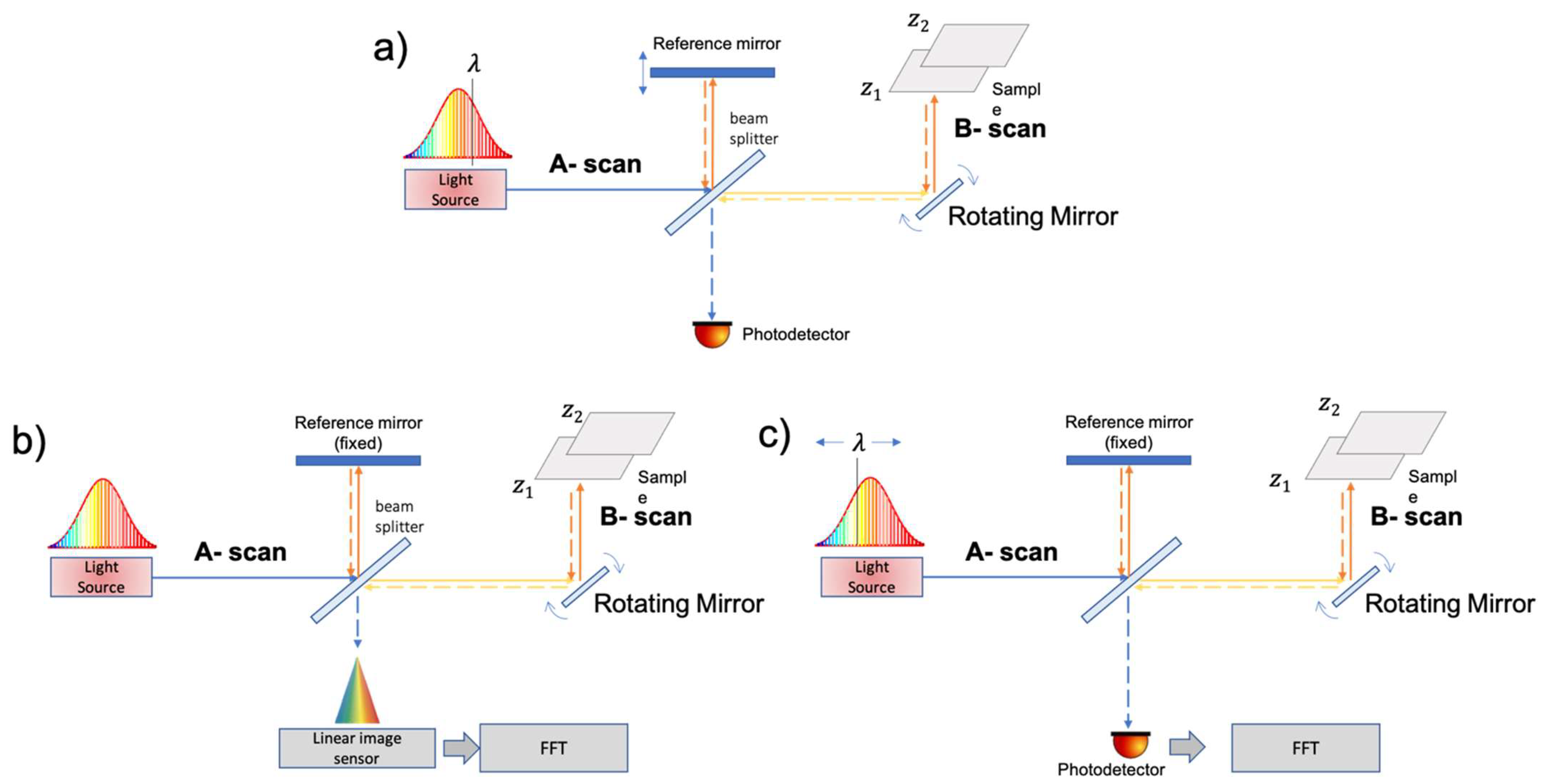
3.2. Optical Coherence Tomography (OCT)

Optical coherence tomography (OCT) is an imaging technology able to provide high-resolution cross-sectional imaging. Since its introduction in 1991 by James Fujimoto [48], OCT has become a standard diagnostic method in ophthalmology, but it rapidly expanded to numerous biomedical and clinical applications. Among these, the cardiovascular field is now one of the most developed scenarios. Although the field of medicine has benefited extensively from optical technologies, its historical roots can be traced back to the early developments of optical low-coherence reflectometry in the telecommunication industry during the late 1980s. OCT is defined as a tomographic technique operating in the optical domain. The tomographic feature is obtained by generating multiple cross-sectional images (slices) of 3D objects. Starting from this 3D modality, OCT is often compared to ultrasound imaging but instead of sound waves operation involves a low-coherence light source. Both methodologies, in fact, produce 3D objects working with A-scan, B-scan, and sweep motion. Both techniques perform images by measuring echo time delay and intensity of back-scattering, but the difference of source characterizes the OCT as an interferometric technique. In fact, it is worth stressing that the speed of light is much faster than that of sound. Therefore, interferometry techniques are necessary to measure the back-scattered: since a direct quantification cannot be achieved on such a time scale.
In this scenario, a common approach to measure the echo time delay of light is to use low-coherence interferometry (LCI), which measures the time delay and the intensity of back-scattered light by interference with light traveling along a reference path [49,50]. The core of LCI instrumentation is the Michelson interferometer shown schematically in Figure 3. The wavelength used is around 1300 nm to minimize energy absorption in the light beam caused by proteins, water, hemoglobin, and lipids.
The first versions of OCT were operated in the time domain (TD-OCT). More recently, a frequency domain, also known as the Fourier domain, (FD-OCT) version was developed. In a TD-OCT operated system, the interference pattern is obtained by scanning the sample in depth by moving a reference mirror. The basic TD-OCT setup is reported in Figure 3a.
A light source emits a low-coherence light wave that reaches a beam splitter which splits the light wave in half. One part of the light wave travels to a reference mirror, where it reflects directly back towards the beam splitter. The second part travels to the sample tissue. The interaction between these two light waves is the basis on which OCT produces images [51].
Generally, for the detection of the near-infrared spectral signals, a high-density line-array or a 2D detector with high sensitivity is used. Classical CMOS or CCD image sensors can be used, but significantly higher sensitivity is achieved with sensors in InGaAs technology. For example, one of the latest cameras for OCT instruments contains a linear InGaAs detector array of 2048 pixels arranged in a 12.5 µm × 12.5 µm pixel format with specifically designed CMOS read-out circuitry.
Distance or spatial information are determined from the time delay of reflected echoes according to the formula ∆T = z/v where ∆T is the echo delay, z is the distance travelled by the echo, and v is the velocity of the sound wave or light wave.
Fourier-domain OCT (FD-OCT) provides an even more efficient way to implement the low-coherence interferometry. In an FD-OCT system, the mechanical movement of the reference mirror is avoided, and this permits a much faster imaging acquisition than scanning of the sample arm mirror. In FD-OCT, the depth information is obtained by a spectrometer thanks to a signal processing of the spectral distribution and by using a fast Fourier transform (FFT) algorithm. In the field of the frequency-domain OCT, there are two main technologies used to measure spectral interference: spectral-domain and swept-source. In spectral-domain OCT (SD-OCT), a broadband light source delivers many wavelengths to the sample, and all are measured simultaneously using a spectrometer as the detector. An SD-OCT system is shown schematically in Figure 3b. In swept-source OCT (SS-OCT), the light source is swept through a range of wavelengths, and the temporal output of the detector is converted to spectral interference. An SS-OCT system is shown schematically in Figure 3c.
In 2003 it was recognized that FD-OCT has a fundamental signal-to-noise ratio (SNR) advantage over TD-OCT with a typical sensitivity improvement of two to three orders of magnitude [52,53]. The SNR improvement of FD-OCT arises from the distribution of the photonic shot noise over multiple separately detected spectral bands instead of a single detection over the full spectral width as done in TD-OCT. Two of the most important parameters for characterizing imaging performance are image resolution and imaging depth.
In terms of resolution, the axial and transverse resolution of an OCT system is independent. The axial (depth) resolution is related to the bandwidth, or the coherence length, of the source. For a Gaussian spectrum, the axial resolution ( Δ z ) is given by:
Δ z = 2 ln ( 2 ) π n λ 0 2 Δ λ
where λ0 is the center wavelength of the source, with a full width at half-maximum of ∆λ, and n is the refractive index of the sample [54]. The lateral resolution (or transverse resolution) is determined by the optics of the sample arm.
Δ x = 4 λ 0 π f D
where D denotes the beam size at the objective lens and f is the effective focal length of the focusing optics. Additionally, in the case of SD-OCT configuration, the depth range is dependent on the spectral resolution of the spectrometer. The maximum imaging depth (zmax) of an SD-OCT is expressed by:
z m a x = λ 0 2 4 n δ λ
where δλ is the wavelength resolution of the spectrometer [55].
Due to the advantages of the superior sensitivity and of the higher speed imaging acquisition, currently the FD-OCT technique is now the most widely used. Instead, in the field of the spectral-domain and swept-source approach, there are some differences in the fields of application even with some dominance of one over the other.
The SS-OCT technique is implemented in devices that are more prevalent in clinical applications of OCT where high speed and deeper imaging is required, such as cardiology, dermatology and gastroenterology. More recently, SS-OCT technology has also been included in ophthalmic instruments although SD-OCT is still the most used variant in this field due to its higher axial resolution than SS-OCT [56].

3.3. Infrared Thermal (IRT)

Infrared thermal (IRT) imaging has been used for medical applications since 1956: thanks to the technology evolving and the improvement in resolution, image size, and portability, IRT is now a useful and non-invasive tool for clinical practice (in neurology, vascular disorders, rheumatic diseases, tissue viability, oncology, dermatological disorders, neonatal, ophthalmology, and surgery) [57] (see Figure 2). Some of the emerging IRT medical applications are microvascular imaging, diagnosis of venous diseases, diagnosis of orthopedic injuries in childhood, monitoring, and prevention of sports injuries, application to safety studies of vaccines, detection of brown adipose tissue activation [38], and assessment of local skin temperature response during an oral glucose tolerance test [58].
IRT is based on the emission of infrared (IR) radiation (or thermal radiation) by all the objects with a temperature above absolute zero. Human skin at 27 °C emits IR within the wavelength range of 2–20 μm, and for medical applications, a very narrow wavelength band (8–12 μm), the far-infrared (FIR) range, is generally used [59].

3.3.1. Instruments

IRT consists of the detection of thermal radiation emitted by the body surface using an infrared camera. Temperature distribution can be measured instantaneously (static IRT), or its temporal variations can be monitored (dynamic IRT), obtaining a series of thermal images that can be analyzed by performing fast Fourier transform (FFT). The electromagnetic radiation is converted into an electrical signal digitized and then transformed into the final thermogram. There are two main types of IR detector: thermal and photonic. The most common type of thermal detector is the microbolometer that changes its resistance due to the incident IR radiation. Photodetectors respond to the absorbed photoexcitation of free carrier charge (photoelectric effect), (Figure 2).

3.3.2. Image Sensors

The third-generation IRT cameras, i.e., those currently used, have large focal plane array (FPA) detectors and on-chip image processing. Detectors can be cooled (quantum detectors) and uncooled (thermal detectors) [57]. Uncooled cameras have a lower thermal resolution (typically 0.05 °C), but they also have many advantages, such as high spatial resolutions, compactness, and portability. Moreover, these cameras are lightweight, manufactured by silicon wafer technology, and are cheap compared to cooled infrared cameras. The typical spatial resolution of infrared cameras equipped with focal plane arrays is about 2 mm over a range of working distances and fields of view (e.g., 200 × 200 mm2 to 500 × 500 mm2 at a distance of 1 m).
Cooled IR detectors are generally made from materials such as InSb, InGaAs, HgCdTe, and layered GaAs/AlGaAs for quantum well infrared photon (QWIP) detectors. Uncooled detectors are generally based on microbolometer technology, i.e., vanadium oxide (VOx) microbolometer arrays, or composed of pyroelectric materials. Quantum detectors are generally more sensitive than thermal detectors; however, they require cooling obtained, for example, by a small Stirling cycle refrigerator unit [60]. This equipment makes the thermal camera more expensive and rather energy consuming.

4. Magnetic Resonance Imaging (MRI)

Magnetic resonance imaging (MRI) can be considered the most sensitive and non-invasive approach for human body imaging, and it has become one of the most important medical imaging techniques for the diagnosis and follow-up of diseases affecting different organs and tissues. MRI requires a strong static magnetic field B0 associated with gradients and radiofrequency (RF) pulses for image production. B0 field strengths from 0.5 T to 7 T correspond to RF field frequency in the range of 21–298 MHz for 1H MR experiments.
The recent technical developments, which comprise increased field strength, improved gradient performance, and advances in RF technology, permitted spatial resolution and sensitivity increase.
The RF field is generated and picked up by transmit and receive coils, respectively (reference [61], p. 137). Since the transmit coil has to produce a highly uniform magnetic field in the desired field of view (FOV), it is usually large, to optimize the field homogeneity and include a significant tissue volume. The receive coil has to maximize signal detection while minimizing the noise. Therefore, its size has to be minimized. In general, both transmit and receive coils have been adapted to the specific application and the human body portion dimensions, but they have to keep good performances with slightly different subjects.

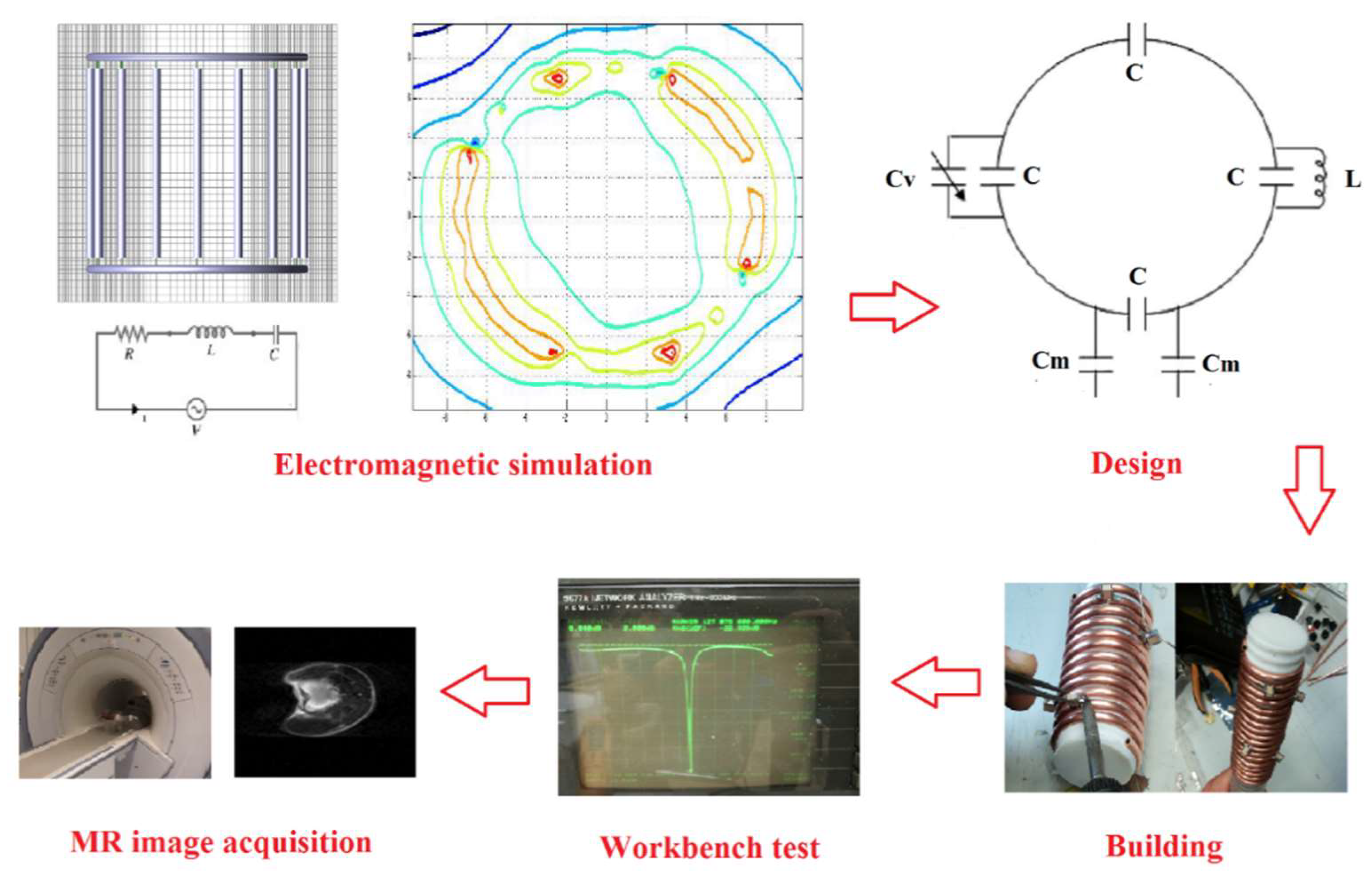
4.1. Radiofrequency (RF) Coils Design, Simulation, and Test

MR coils can be categorized into volume, surface, and phased-array coils, according to their shapes [62]. Volume coils are often used both as transmit and receive coils thanks to their potential to generate a uniform field in a large region surrounding the human body portion. Surface coils are constituted by loops of various shapes and are much smaller than the volume coils. They usually provide higher SNR but with relatively poor field homogeneity. Phased-array coils [63], whose each element is constituted by circular or rectangular loops, permit a good SNR to be achieved, typical of surface coils, with a large sensitivity region, usually obtained with volume coils. The most important challenges in designing array coils are the minimization of the mutual coupling between the coil elements for avoiding SNR losses, while an optimal image reconstruction algorithm has to be successively employed for combining the individual coil images into a single composite image with full FOV [64].
In RF coils, the flowing current has to be maximal at the Larmor frequency (f0 = γ/2π B0, where γ is the gyromagnetic ratio with 42.58 MHz/T value for 1H nucleus), which corresponds to the coil resonant frequency:
f 0 = 1 2 π L C
where C capacitance mainly results from the discrete capacitors contribution and L inductance takes into account the energy stored in the magnetic field. The current flowing in the coil is mainly limited by loss mechanisms (schematized with a R total resistance) which take into account the conductor loses ( R c o i l ), sample losses ( R s a m p l e ), and tuning capacitor and radiative losses ( R e x t r a ). This RLC circuit is characterized by a Q quality factor defined as (reference [61], p. 140):
Q = 2 π f 0 L R t o t = 1 R t o t L C
and by the ratio r between the unloaded coil quality factor ( Q u n l o a d e d ) and the one with the coil loaded with the human body portion or a phantom which mimick it ( Q l o a d e d ):
r = Q u n l o a d e d Q l o a d e d = 1 + R s a m p l e R c o i l + R e x t r a
Typical values range from 50–500 for Q and from 2–5 for r.
The coil L inductance depends on the conductor size and typology (strip or wire geometries) and can be evaluated with the following expression (reference [61], p. 58):
L = μ 0 4 π I 2 V V J ( r ) J ( r ) R d v d v
where J is the current density in the conductor, μ0 is the permeability of free space, I represents the total current in the conductor, V is the conductor volume, and R = |rr’|.
The magnetic field homogeneity is another important parameter in the coil design since it strongly affects the FOV. For estimating the coil’s magnetic field pattern, two different approaches can be used. The first one is based on magnetostatic theory, which implies the assumption of a nearly static field, valid for coils whose size is much smaller than the wavelength. This approach has been demonstrated as useful for the design and simulation of low frequency-tuned coils constituted by circular and linear conductor segments [65], in which the magnetic field calculation has to be performed by subdividing the coil conductor into small segments for separately studying their total magnetic field contribution. In a practical way, the evaluation of the three-dimensional magnetic field pattern produced by the current flowing in a coil can be performed with the Biot–Savart law by neglecting the conductor dimension with respect to the wavelength and by treating the conductor as a very thin wire. When the coil tuning frequency increases, RF fields interact more strongly with the human body, and the magnetostatics approach is not more suitable for coils design and simulation. In this case, different electromagnetic-numerical methods based on solutions to Maxwell’s equations have to be employed for field calculation [66], including the Finite-Difference Time-Domain (FDTD) [67], the Finite Element Methods (FEM) [68], the Method of Moments (MoM) [69].
After simulation and building, MR coils are tested at workbench for evaluating their performance. A practical way to perform Q coil quality factor measurement is by using the following equation:
Q = f 0 B
where B is the −3 dB coil bandwidth.
Equation (8) can be used to measure both loaded and unloaded coil quality factors and, successively, for r ratio estimation, according to Equation (6).
Such measurements can be performed easily by using a dual-loop probe, consisting of two pickup loops partially overlapped to minimize the mutual coupling between the elements, and a network analyzer. Finally, coil performance has to be evaluated in a scanner using standardized image quality parameters with phantom and human experiments. Figure 4 summarizes the simulation, design, and test phases for an RF coil.
The circuit shown in the right-hand side of the top of Figure 4 depicts the sketch of a simple RF circular coil, characterized by Rcoil resistance and L inductance, where C and Cv are, respectively, the fixed and variable tuning capacitances, and Cm are the matching capacitances.

4.2. Recent Developments in RF Coil Technology

4.2.1. Phased Array Coils

Since the invention of phased-array coils, manufacturers of MR scanners have developed and marketed multiple receiver channel systems to take advantage of the extended FOV and increased sensitivity guaranteed by such coil design [70]. Today’s clinical MR scanners are typically equipped with 16- and 32-channel coils, while larger configurations approaching 128 channels have been proposed for accelerated cardiac MRI [71]. Despite the fact that historically phased-array coils have been commonly employed only in receive mode, different approaches involving transmit/receive phased-array coil were proposed for providing a highly uniform tissue excitation, thanks to the possibility of independently exciting separate parts of the human body, thus overcoming the variations in RF field penetration [72]. Parallel transmitter array coil was proposed for cardiac MRI [73], and an improvement of image quality and speed was obtained thanks to the increase in the number of transceiver coils in cardiac imaging at 7 T [74]. The use of flexible form-fitting phased-array coils assembled to be conformed to the anatomy of various sizes or shapes can significantly reduce the spatial distance between the coil and the human body portion, thus achieving the maximization of the image SNR [75]. Moreover, the use of a modular structure permits minimizing coupling between neighboring coil elements when the array is bent differently [76]. A novel approach useful for flexible and adaptive coils is based on the use of special conductive material (INCA conductor), which permits the achievement of a very high flexibility while maintaining the electromechanical features [77].

4.2.2. Digital Coils

In conventional MR scanners, connection cables are employed for connecting the coil to the analog-to-digital converter (ADC), which inevitably gives rise to cross-talk and SNR decrease and becomes increasingly severe when the channel number increases. Moreover, currents induced on the cable shields can lead to local heating, which can increase the patient risk. Digital coils overcome these effects by implementing analog-to-digital conversion of the MR signal in the receive coil, with such a signal sampled and digitalized directly in the coil chassis and successively transmitted to the image processor by optical fibers or wireless technology [78]. In particular, optical fibers guarantee patient safety while reducing signal interferences, although problems related to placement and curvature of the fibers still limit the coils positioning and handling. Wireless coils seem to enable the building of “wearable” coil arrays, which improves patient comfort and supports the integration of different channels at the coil level: in this way, channel number is exclusively dependent on the coils and not on system ADC inputs number as for the standard scanner [79].

4.2.3. Catheter Coils

Catheter coils are configurations in which the signal is detected by small coils embedded inside catheters. They are mainly used for intravascular MRI or active catheter tracking both for interventional and diagnostic purposes. Such coils permit high-resolution blood vessel images and provide an alternative to other imaging techniques (i.e., computed tomography or X-ray fluoroscopy) for image-guided endovascular interventions. For achieving the best SNR, the RF field has to be maximized, and simultaneously the electric field minimized. Such coil performance optimization can be performed by using a small wire diameter, material covering the coil with good dielectric properties, and high decoupling from the transmit coil while, for permitting blood vessels navigation, a flexible material has to be employed. Ideal choices minimizing the detected area within the limited vessel space are an elongated loop design [80] or a thin dipole-based loopless antenna [81]. Furthermore, remote orientation for image-guided interventions can be performed by exploiting the catheter coil’s magnetic properties: catheter guidance can be performed manually or by using the torque experienced by the coil when an electric current flows on it in the presence of the main magnetic field [82].

4.2.4. Reconfigurable Coils

Surface coil size affects both SNR and FOV since when the radius decreases, the SNR becomes higher, but the FOV decreases. As a result of this trade-off, different coil sizes are required for obtaining images with the best SNR in each case, with the need for subject repositioning during imaging in channel count limited scanners. To address this issue, a reconfigurable surface coil, which can be switched between a smaller and a larger configuration with high SNR in both cases, and a reconfigurable phased-array coil switched between a spine and a torso mode, have been recently presented for adapting the geometry when multiple FOV imaging is necessary [83]. Such reconfigurable coils employed microelectromechanical system (MEMS) switches integrated into the coil, which enables and disables conductive sections and capacitors for reconfiguring and tuning the coil while maintaining the coil impedance matching in each configuration. The employed MEMS switch has to be non-magnetic, with low series resistance in the switch closed state for minimizing the impact on the SNR and fast switching time for rapidly changing the coil configuration.

4.2.5. Patient-Specific Coils

As previously described, a significant SNR improvement and a consequent diagnostic image quality can be achieved by placing coils close to the body. However, commercially received coils do not optimally fit every patient because they are typically designed for accommodating the largest possible subjects, and in some cases the gaps between the coils and the body can degrade the SNR. Moreover, conventional coils are not designed for reproducible patient positioning and do not limit the patient’s movement, leading to motion artifacts. Very recent literature [84] described a method for additive and rapid manufacturing of 3D patient-specific coils, with the characteristic of ensuring a perfect fit to the body parts with complex geometries like a neck. The developed method employed spray deposition of silver nanoparticle inks and dielectric materials on 3D printed substrates for constituting high-quality coil components, with the result that the prototype patient-specific coil array exhibits up to five times higher SNR than a commercial coil array, with a potential application in cases when patient reproducible placement is important, as for MRI guided surgeries.

4.2.6. Metamaterials

Metamaterials are artificially engineered media with particular properties like permeability not found in natural materials, whose research was historically concentrated in microwave region at frequencies higher than Giga-Hertz. In the last few years, magnetic metamaterials have been applied in MRI for increasing SNR and for enhancing the RF magnetic fields [85], thanks to their capacity to interact with electromagnetic radiation. In particular, when the resonant mode frequency coincides with the coil resonance frequency, both transmit and receive local RF magnetic fields increase are achieved, thus leading to an SNR gain and permitting a great improvement in the detection and characterization of smaller abnormalities in tissue features [86]. Metamaterials were recently employed even for elements decoupling in phased-array coils [87].

5. Computed Tomography (CT)

The basic design of a modern multi-slice CT (MSCT) scanner is depicted in Figure 5. The X-ray tube and the detector’s array are placed on the opposite sides of a circular structure rotating around the circular opening of a ring-shaped structure called a gantry. During a CT scan, the patient’s bed slowly moves through the gantry while the X-ray tube rotates around, shooting narrow beams of X-rays through the body. X-ray detectors detect X-rays crossing the patient’s body and transmit the detected signal to a computer-based data processing system able to reconstruct the tomographic view of the body. In modern scanners, the detectors are arranged in a 2D array, consisting of a large number (750 or more) of detector elements in the rotating direction to intercept the whole X-ray fan-beam. Each detector element is further divided into several smaller detector elements. Hence the 2D detectors array is constituted by multiple, parallel rows of detectors. The MSCT design allows multiple slices to be simultaneously acquired in the z-direction with a slice thickness proportional to the size of the single detector [88]. Today, scanners provide submillimeter detector elements with the number of available detectors in z-direction ranging from 64 to 320.
Detectors represent a key component and are crucial for obtaining good CT image quality [89], especially in cardiovascular applications [90]. In fact, the spatial resolution of a CT scanner can be expressed as [91]:
R e f f = 1 M d 2 + ( M 1 ) 2 s 2
where M is the scanner magnification, s is the X-ray spot size, and d is the detector size. Hence, the scanner resolution is linearly proportional to the detector size, and small detectors provide high image resolution. Detectors should also fit several other requirements: accuracy, as precision in X-ray flux measurement, is important to separate tissue types; dynamic range, as CT systems are characterized by a large signal dynamic (104–105); stability, as system calibration should be preserved through time; the speed of response, as acquisition time should be minimized. Moreover, spatial and temporal cross-talk between detectors should be minimized.
The detection efficiency for a CT scanner can be defined as:
DE = GDE × DQE,
where GDE is the geometric detection efficiency (the ratio between the detector active area and the full detector size) and DQE is the detective quantum efficiency (the squared ratio between the SNR at the detector output and the SNR at the detector input [92]. Hence, to improve DE, the active area should fill the whole detector size, and electronic noise should be minimized.
Although direct detectors (i.e., photon-counting detectors, PCD) are employed in other image modalities, as SPECT and PET, PCD current technology is still not adequate for clinical CT imaging, mainly due to the low tolerance of PCD to the high X-ray flux rates typical of medical CT. Hence, indirect detectors, adopting a two-step process, dominate the current CT technology.

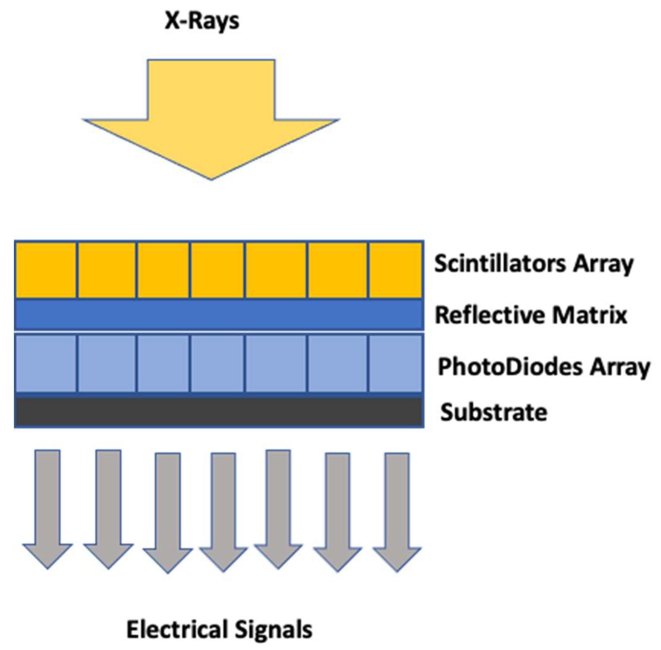
5.1. Indirect CT Detectors

Standard CT detectors are indirect converters, adopting a two-steps process. Firstly, the X-ray energy is converted into visible light by a scintillator. Secondly, visible light is captured by a photodiode (PD) and converted into an electric current. The structure of an indirect CT array detector is schematized in Figure 6.
As previously stated, modern CT scanners are characterized by a multi-slice CT geometry, where scintillators are typically arranged in two-dimensional arrays. The scintillator array design includes a reflective material matrix (i.e., high reflectance pigment or sputtered silver on a polymer). The reflective matrix mechanically supports the PD array (PDA), minimizing the cross-talk between PDA elements. Each element of the PDA is connected to a dedicated low noise pre-amplifier. The signal is integrated over a certain time and sent, after digitalization, to the image reconstruction module.
Although scintillators are used in several medical imaging modalities, the requirements of CT scanners are likely the most demanding. Requirements include high light output (i.e., X-ray conversion efficiency and optical transparency), high X-ray stopping power, radiation resistance, stability in respect to time and temperature, and compactness. CT scintillators are commonly built by single crystals and polycrystalline ceramics. Mostly used materials are CdWO4 (cadmium tungstate), Gd2O2S:Pr,Ce (GOS), and (Y,Gd)2O3:Eu. CdWO4 and (Y,Gd)2O3:Eu scintillators achieve the best stopping power (about 2.6 mm at 140 KeV) with a short decay time (about 2 μs). CdW04 scintillators have an acceptable light yield (about 3K ph/MeV) with a small temperature dependence and are the most commonly used materials in clinical CT scanners [93].
As the performances of current scintillators are far from the theoretical limit [94], research on new material is ongoing. Garnet of the type (Lu,Gd,Y,Tb)3 (Ga,Al)5O12 represents a promising solution providing better transparency and greater yield [95]. The GE GemstoneTM represents the first garnet-scintillator used in commercial CT scanners. Another interesting material introduced in some Philips CT scanners is ZnSe:Te, which is particularly efficient in the design of dual-energy CT detectors [96].
The function of PDA is to collect light signals from the scintillator’s array and convert them to electric signals. PDA operates at zero bias (between 100 µV and −100 µV) to minimize leakage currents. PDA to be used in an advanced CT scanner should meet several constraints, as high responsivity (>0.35 A/W), high shunt resistance (>1 GΩ), minimal cross-talk (<4%), high linearity (<0.1%), and short response time (10–30 µs) [89].
The integrated acquisition electronics collect the electrical signals from the PDA and convert them to digital signals. A key point in indirect detector design is reducing electronic noise intrinsic to the detector [97]. Less electronic noise allows image noise to be significantly reduced when only a few X-rays reach the detector, allowing the use of low-dose settings (few milliamperes second) as desirable for pediatric scans or screening programs. Electronic noise can be reduced by decreasing the distance between the photodiode and the analog-to-digital converter electronics. This is achieved by designing more compact electronics that can be placed closer to the detector pixels and require shorter analog wires. The latest step includes fully integrated electronics that have become possible with new contacting technology, the so-called through-silicon vias [89]. With such a technology, the analog distance can be reduced to a few millimeters.

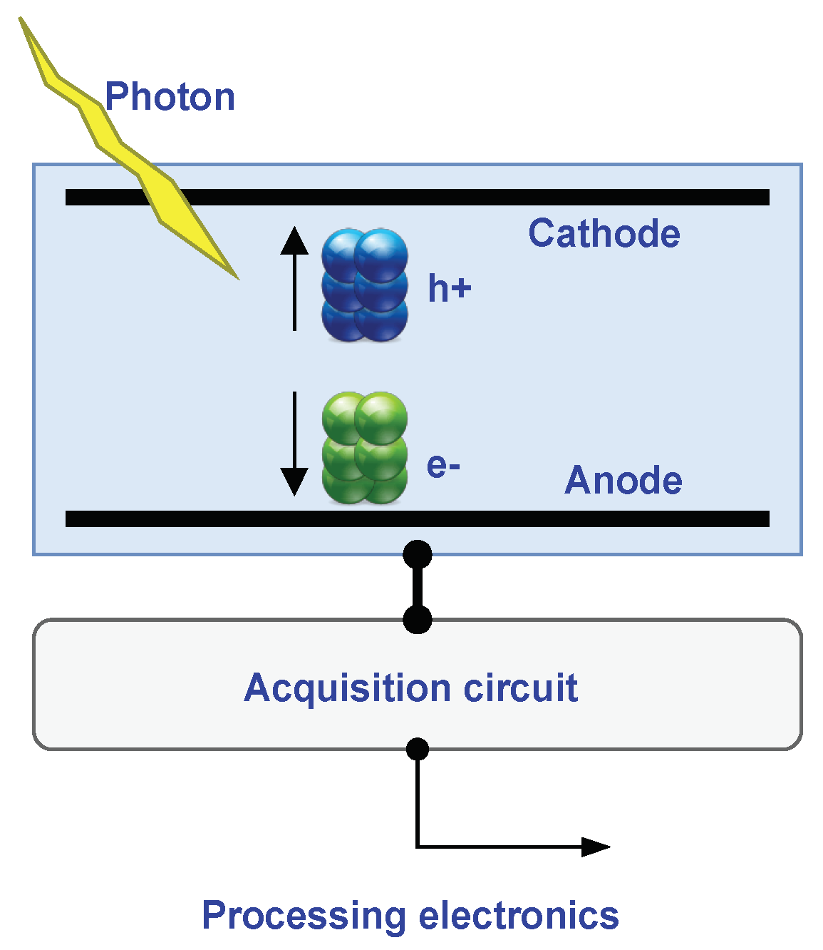
5.2. Direct CT Detectors
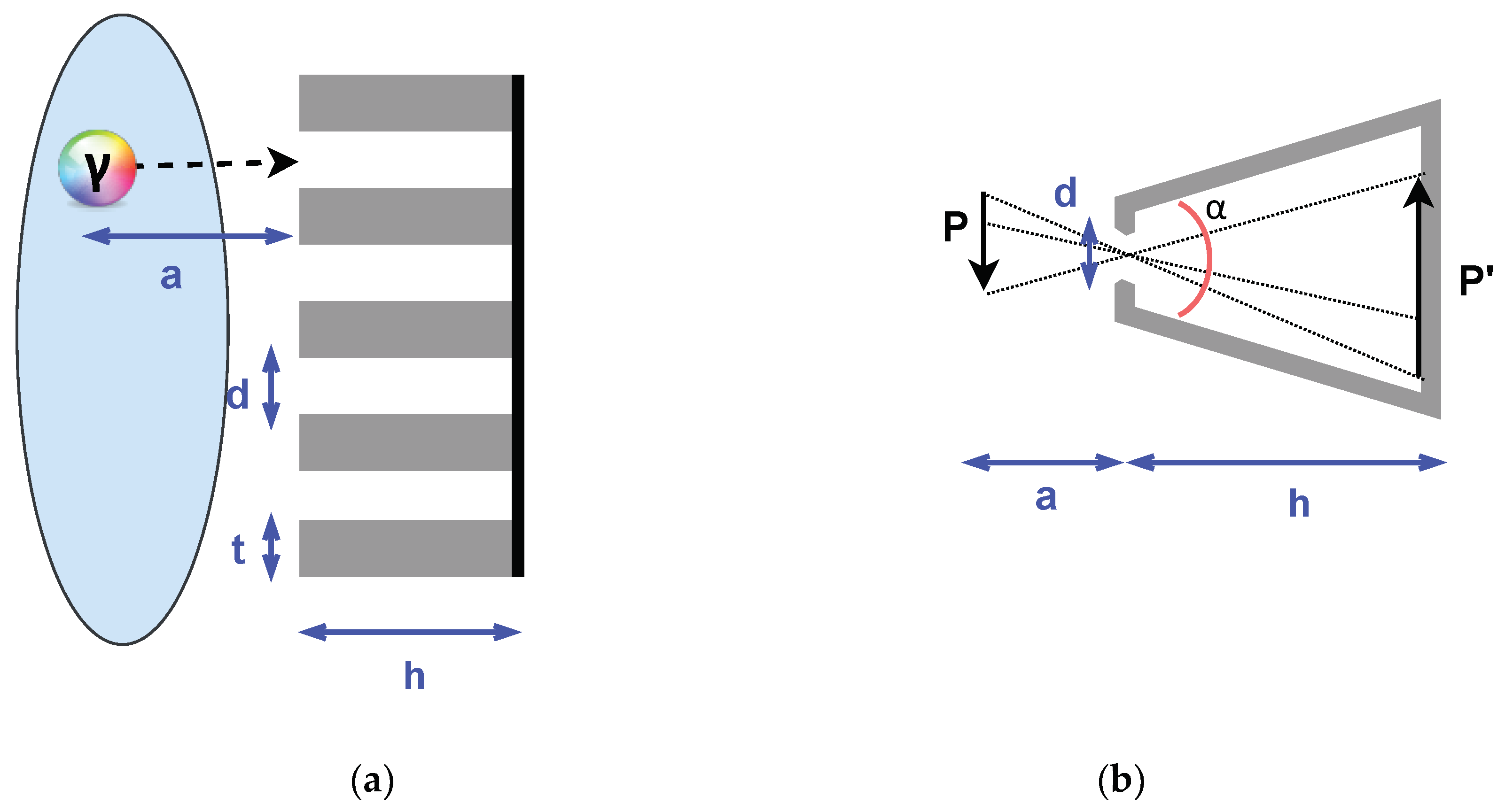
As will be described in Section 7, direct detectors, able to directly convert X-rays into an electric signal, have several advantages against indirect detectors. Hence, the introduction of direct PCD would represent the next major step in the development of clinical CT [98]. As previously pointed out, despite the fact that PCD detectors are employed in other image modalities, such as SPECT and PET, PCD current technology is still not adequate for clinical CT imaging, mainly due to the low tolerance of PCD to the high X-ray flux rates typical of medical CT. Another problem is represented by the need to arrange PCD in 2D arrays composed of low-size elements. There are currently two main converter material candidates: cadmium (zinc), telluride (CdTe or CZT), and silicon (Si). The major difference between CdTe/CZT and Si detectors is the relative X-ray stopping power, which is about 30 times better in CdTe/CZT. Hence, CdTe/CZT based PCD seems to be the best candidate for clinical use in CT scanners.
PCDs have several advantages compared to scintillator-based detectors. The separation layer (about 0.1 mm) needed in scintillator-based detectors design reduces the dose efficiency due to the layer’s absorption. As the layer width cannot be reduced, decreasing the size of the scintillators will reduce the geometric efficiency, limiting the achievable spatial resolution of scintillator-based detectors [99]. Instead, the geometrical dose efficiency of a PCD is only reduced by the unavoidable anti-scatter collimator blades or grids. By contrast with scintillator detectors, each “macro pixel” confined by collimator blades can be divided into smaller sub-pixels which are read-out separately to increase the spatial resolution further.
During the last decade, there has been important research activity in the field of the use of PCD in CT scanners, both in hardware development and in the investigation of the relationship between PCD technology and improvements in image quality. The first studies on volunteers were performed by PCD CT prototypes demonstrating comparable performances in respect to state-of-art indirect detectors [100]. The adoption of PCDs for CT also would allow the clinical introduction of new imaging techniques as a combination of photon-counting CT with dual-energy acquisition [101] or phase-contrast imaging [102].
The lowest energy threshold of CdTe/CZT detectors is 20–25 keV, with a typical energy resolution (FWHM) of 5–10 keV [98].

5.3. CT Collimators

The interaction of X-rays with a patient’s body is associated with coherent and incoherent scattering. In practice, only a small portion of the X-rays is directly absorbed by the detectors [103]. Scattering is associated with significant degradation of image quality, especially in large patients. The scattering phenomena can be effectively reduced (by a factor of 10) by anti-scatter grids (ASGs) collimators placed in front of the detectors array [104]. Two-dimensional ASGs are commonly used in CT scanners as they reduce scattering more effectively in respect to mono-dimensional ASGs.
Moreover, the 2D structure is more robust in respect to the vibrations induced by the fast rotation of the gantry. The precision in realizing the ASGs geometry is challenging as the alignment between ASG and detector array channels should be almost perfect in both directions. ASGs are developed by using lamellas made of X-ray absorbing material positioned between the detector cells. Materials used in the construction of ASG lamellas should have a high Z number (molybdenum, tungsten) to ensure effective absorption of scattered radiation. An inherent disadvantage of ASGs is the reduction of GDE as ASGs lamellas reduce the detectors’ active area.

6. Nuclear Medicine Imaging

6.1. New Generation Photon Detectors: CZT Technology

As previously noted, CdTe and CZT (or CdZnTe) wide band gap semiconductors have been recently proposed as X-ray and gamma-ray detectors [105,106,107]. Among the traditional high-performance compound semiconductors based on silicon (Si) and germanium (Ge), CdTe and CdZnTe detectors show high detection efficiency and energy resolution, good room temperature performance, and are well suited for the development of compact and reliable detection systems.
CdTe and CZT detectors are semiconductors, so-called direct-conversion devices: in comparison to scintillators, they avoid the random effects associated with scintillation light production, propagation, and conversion to an electrical signal.
In medical imaging, CZT detectors are widely proposed [108,109,110], and there are several commercially available tomographs that include this type of detector [111,112,113].
Having a high density (~5.8 g/cm3) and effective atomic number (Zeff~50), CZT semiconductors confer a high attenuation power on incident radiations. They have a high energy resolution (<6% FWHM) compared to traditional NaI (~10% FWHM): this reduces the detection of scattering events, increasing the contrast-to-noise ratio (CNR) and spatial resolution. The excellent energy resolution makes it possible to discriminate different energy peaks so as to be able to perform the simultaneous acquisition of multiple photopeaks (i.e., in SPECT) resulting from multiple radioactive isotopes or from an isotope that emits at multiple energies, with more precision.
CZT detectors are also characterized by high sensitivity: a 140 keV gamma photon produces about 30,000 electrons, i.e., 10 times more than those produced using conventional scintillators and PMT devices; this advantage means less activity and a shorter acquisition time are necessary to obtain useful images.
The immediate digital conversions and localizations also allow the noise connected to the analog components to be reduced: in traditional cameras, the radiation is first converted into visible light by the crystals, which is then transformed into an electrical impulse by the PMTs. Therefore, there is an indirect conversion, followed by a localization operated by a special circuit, as opposed to the direct one that takes place in the CZT crystals.
Thanks to their reduced thickness and flexibility in size [106], they offer greater structural compactness and greater freedom in the design of imaging devices.
The operating principles of a CZT detector can be described, briefly [106,114,115]: the incident photon with the crystal lattice of CZT produces primary electrons that will undergo impact ionization to generate secondary charges; the secondary charges are pairs of electrons and holes (e–h), where a hole is the positively-charged electron vacancy in the valence band left when the electron has been promoted into the conduction band and the holes left in the valence band. The application of an external voltage between the detector electrodes gives rise to the signal current that can be processed by the read-out electronics. Figure 7 schematically shows the main components for a CZD detector-based system: h+ and e are the secondary charges generated by the incident photon (yellow line) with the crystal lattice; the signal current generated by the application of the external voltage is then acquired (acquisition circuit in Figure 7) and processed (processing electronics in Figure 7).
If a high energy photon (X-ray or gamma-ray) interaction creates N0 e–h+ pairs at a distance x between the point of interaction and the cathode in a planar detector of thickness L, then the induced charge on the electrode is given by the Hecht equation [116]:
Q = N 0 q [ λ e L ( 1 e L x λ e ) + λ h L ( 1 e x λ h ) ]
where q is the elementary charge, λ e and λ h represent the mean drift lengths for electrons and holes, respectively.
The charge collection efficiency is not only dependent upon material properties but also the distance charged secondaries must traverse to reach their respective electrode and the magnitude of applied voltage [115]. The mobility of electrons tends to be much higher than that of holes, so most of the electrical signal is mainly due to charge collection efficiency at the anode. However, hole mobility cannot be too low, as inefficient charge collection due to poor hole mobility causes photopeak broadening for events that occur far from the cathode.
One method of obtaining spatial information from a semiconductor detector is to use so-called pixel detectors [114,115,117] in which a series of square pixels are patterned on one detector side, typically the anode side. In this case, only a single side of the detector must be read out to obtain two-dimensional position information.
An alternative to the pixel-detector method is the orthogonal strips on opposing sides disposition of the crystal [107,115]. In these double-sided strip detectors, charge signals are read out from both sides in coincidence, and the two-dimensional interaction position of the incident photon must be estimated from the combination of strips with the signal on each side. With respect to the pixelated configuration, the cross-strip configuration allows the number of electrodes required to produce the same position resolution across the same volume of the detector to be reduced (from N2 down to 2N), greatly relieving the burden for the read-out electronics [107].

6.2. Single-Photon Emission Computed Tomography (SPECT)

In SPECT, a radiotracer is injected intravenously into a live animal or human subject and participates in the body’s metabolism, and distributes accordingly. The radiotracer is labeled by gamma-ray (single-photon) emitting radioisotopes; following radioactive decay, photons are emitted in all directions and exit the body to be suitably detected by a gamma camera, converting gamma-rays into an electronic signal. In the past, the gamma cameras were composed of a matrix of NaI scintillator crystals that convert photons into visible light, with a collimators grid on the side facing the patient and a matrix of PMTs on the other; PMTs convert visible light into an electrical signal that is welcomed by localization and processing electronics, which generate the output which is then stored in suitable data matrices, i.e., sinograms.

6.2.1. CZT Detectors in SPECT

In the latest generation of SPECT cameras, the crystals NaI scintillators and PMT tubes have been replaced by CZT semiconductors, which are much more compact and with better energy resolution, detector sensitivity, spatial resolution, and modulation transfer function [108,118]. The increase in count sensitivity compared to NaI requires less activity necessary to form useful images and a shorter acquisition time: for example, for cardiological imaging, if for traditional cameras it took about 30 min to complete an acquisition, for modern cameras less than 10 min are required. Medical doctors are, therefore, given the possibility to choose between dose reduction, thus reducing radiation exposure and rapid acquisition.
Typical CZT detectors used in SPECT are compounds of a square surface composed of a matrix of pixels (usually 16 × 16 [119] or 32 × 32 [113]) on each side. Each pixel represents the smallest element of detection, thus allowing very low spatial resolutions to be reached: up to 2.5 mm, against the 4 mm achievable with NaI crystals.

6.2.2. Collimators in SPECT

In order to better establish the original locations of radiation detected by the detectors, physical collimators with holes or channels are usually installed next to the face of the detectors closest to the gamma-ray emitting source, allowing only the passage of photons traveling in specific directions. They are a compound of holes and channels providing optimal spatial resolution but reducing the system sensitivity because only those photons not stopped by the collimator materials and passing through the holes and open channels are detected (typically ~10−4–10−2); the majority of the gamma rays are absorbed and stopped by the collimator materials. In fact, collimators are usually made of materials with a high density and a high atomic number, such as lead, tungsten, gold, and platinum; all of them have relatively high attenuation coefficients for absorbing gamma rays.
There are several types of collimator present in the SPECT cameras, which differ in the orientation of the holes, thickness of the metal, and hole width, such as [120]: fan beam, parallel hole, and pinhole. Which type of collimator is better to use for a given imaging application depends mainly on the ratio between the size of the FOV, the size of the imaging detectors, and the required spatial resolution and/or sensitivity. The simplest type of collimator is the parallel hole (Figure 8a), consisting of a grid with parallel holes. Only photons coming from a tight cone-shaped region in a direction perpendicular to the entrance surface of the collimator can fully traverse the collimator hole and reach the detector.
For a point source, the resolution R p a r of parallel hole collimators are given by [121]:
R p a r = d h + a h e f f
where d is the distance between two sectors, a is the distance between the collimator and the emission site, h is the length of the collimator and h e f f = h 2 / μ takes into account the penetration factor of the collimator using the attenuation coefficient μ characteristic of each metal (Figure 8a).
The dependence of the spatial resolution of the imaging system on the collimator resolution is described by:
R s y s = R i 2 + R p a r 2
where R i is the camera’s intrinsic resolution.
A pinhole collimator consists of a small pinhole aperture in a plate of dense material such as lead or tungsten (Figure 8b). The collimator resolution R p i n , and the system resolution R s y s for a pinhole configuration are given by [121]:
R p i n = d e f f h + a h
R s y s = R i 2 M + R p i n 2
where d e f f   is the effective diameter of the hole:
d e f f = a ( a + 2 μ t a n ( α 2 ) )
It is >d and depends on the attenuation coefficient μ and the opening angle α.
The region of interest is projected through the aperture onto the detector magnified by a factor of M (Equation (15)), as schematically shown in Figure 8b by P and P′ (P′ > P).
The sensitivity of a single pinhole collimator is rather low and, for this, if the detector is large enough, multiple pinholes are combined, generating a multiple-pinhole collimator; with this arrangement, the sensitivity is very high, and it is possible to make acquisitions from rather narrow anatomic district areas, such as the thyroid or the heart [122,123]: by positioning the patient appropriately, it is possible to accurately acquire the area of interest, reducing noise and background signal contributions, obtaining a system resolution R s y s better than the intrinsic resolution of the R i detector.

6.3. Positron Emission Tomography (PET) Imaging

Like SPECT, positron emission tomography (PET) is a non-invasive imaging modality that gives functional and molecular information from a living organism (animal or human) after the injection of a positron-emitting radiotracer. The radiotracers for PET applications are analogous to common biological molecules such as glucose, peptide, and proteins, in which a radioisotope is used to substitute one of the constituents of the tracer. Thanks to its high sensitivity to differences in the metabolic and biological activities at the molecular level, PET imaging is considered the gold standard among the imaging methodologies for studying biological and clinical phenomenology at the molecular level. It is currently used in a wide variety of clinical areas, such as oncology [124], neurology [125,126], and cardiology [127,128,129].
PET imaging is based on the coincidence detection of two 511 keV gamma-ray photons that are generated when a positron released by the radioisotope annihilates with an electron. These two annihilation photons travel in almost opposite directions [130], so the annihilation occurs on the line connecting the positions where they are detected, called the line of response (LOR). Ignoring attenuation of the gamma-ray photons by the subject, the number of coincidences detected along a particular LOR is proportional to the number of annihilations occurring on the LOR, which in turn is proportional to the sum of the radioactivity along the LOR. Modern PET systems employ multiple rings of detectors surrounding the subject; therefore, PET measurement provides ray sums of the radioactivity distributed along with a large number of LORs, arranged in a 3D configuration. These raw data are then used to generate static 3D or dynamic (4D) PET images by appropriate reconstruction algorithms [131,132,133,134].

PET Detectors

In PET imaging systems available currently in clinics, detectors consist of an appropriate arrangement of scintillators to convert the high-energy gamma-ray to low-energy visible light and photodetectors, which transform the low-energy photons into an electrical signal.
The timing resolution of a scintillator-photodetector-based PET system is largely determined by the performance of the individual modules, including crystals. Coincidence timing resolution (CTR) is an important index for evaluating the efficiency of detectors for a PET system: the main objective in the design and construction of efficient detectors for PET tomographs is to reduce the CTR as much as possible. This also allows the additional time-of-flight (TOF) information to be incorporated into the PET image reconstruction [135,136] increasing the image SNR and effective sensitivity. Among the various scintillators, LSO, LYSO, MLS, GSO: Ce, Zr, LGSO, LaCI3, LaBr3, BGO, CWO [137,138] are the most used. In particular, LSO and LYSO are considered the option of choice for fast scintillation counters, an even faster and more luminous scintillation material. Furthermore, LSO is often used in hybrid PET/CT systems because the same scintillator is used for the PET component and the CT component.
As regards photodetectors, in commercial PET tomographs, there are mainly three types of photodetector being employed [107,136]: photomultiplier tubes (PMTs) [139], avalanche photodiodes (APDs) [140], and silicon photomultipliers (SiPMs) [141].
However, the most advanced detection technology for PET imaging is the use of direct count detectors such as CZT [107]. One of the characteristics in the use of CZT elements in PET is the arrangement of the detectors, which must surround the subject under examination, on 360°. Since the excellent position resolution (<1 mm FWHM) and energy resolution (<3% FWHM @ 511 keV) make CZT sensors perfect detectors for small-sized PET systems at the moment, some prototypes have been designed and developed for small animal imaging [142,143], in which the bore is small in size. Unfortunately, CZT detectors are currently not suitable for human applications because the CZT detectors suffer more from time jitter and time walk, degrading the CRT into the range of tens of nanoseconds. In fact, in CZT semiconductors, since the sensitivity of the electrodes varies spatially, the output signal carries a relatively high temporal variance, and consequently, a degradation of the CRT. One possible solution is to reduce the distance between the two electrodes in order to reduce the drift time of the charge carriers [144]; this would allow a CRT to be achieved low enough to help reject random events. However, by using a thin CZT detector, more detectors are needed to build a detector ring, and this inevitably increases the cost of fabrication of the CZT detectors and read-out electronics due to the increased signal channels. Therefore, at the moment, further research is needed in order to realize the CZT-based PET system for clinical applications.

7. Discussion and Conclusions

This review describes the state of art and the future prospects of the sensors used in medical image modalities currently used in the clinical setting.
Most of the described modalities could be scaled for small animal imaging or even at the microscopic scale. There are several medical image techniques in development that could enter the clinical scenario in the near future and are not covered in the present review. Electrical impedance tomography (EIT) evaluates the impedance in a region of interest by measuring currents or voltages at the electrodes located on the boundaries by solving the associated inverse problem [145]. EIT sensors are arrays of planar electrodes placed on the patient’s body surface. Analog or digital measurement systems could be used, the most recent developments using digital technologies, such as digital signal processors (DSP) and field programmable gate arrays (FPGA) [146]. Medical microwave imaging (MWI) has been studied as a technique for the detection of early-stage breast cancer [147]. MWI sensors are typically designed as arrays of monopole antennas tuned on the microwave frequency range. Various radar topologies have also been proposed for medical applications, namely UWB, CW, and FM-CW [148]. FM-CW radar based on the Doppler effect was used to monitor in a non-intrusive way heart and breath rate [149]. Magnetocardiography is a non-invasive contactless method to measure the magnetic field generated by the same ionic currents that create the electrocardiogram [150].
Table 1 shows parameters and properties that allow comparisons between the imaging methods and the sensors discussed in the paper. Advantages and current limits for each method are also described.
From the analysis of the role of detectors in the various imaging methods, we can say that they constitute a very important part in determining the quality of the resulting image, including temporal and spatial resolution. New materials and new technologies for the design and development of detectors are always growing, in order to improve the ability to detect the received wave and transform it efficiently into an electrical signal. From the overview of the detectors described in this review and used in the different imaging systems, we can say that a lot has been done in recent times, but also that new designs described in the literature will certainly lead to the realization of even more efficient detectors.

Author Contributions

Conceptualization, L.L., M.F.S.; Methodology, M.F.S., L.L. and V.P. Writing—Original Draft Preparation, L.L., V.H., S.C., G.G., V.P., M.F.S. All authors have read and agreed to the published version of the manuscript.

Funding

This research received no external funding.

Conflicts of Interest

The authors declare no conflict of interest.

References

  1. Uchino, K. Piezoelectro composites. In Comprehensive Composite Materials II; Elsevier: Amsterdam, The Netherlands, 2017; pp. 613–624. [Google Scholar] [CrossRef]
  2. Harput, S.; Tortoli, P.; Eckersley, R.J.; Dunsby, C.; Tang, M.X.; Christensen-Jeffries, K.; Ramalli, A.; Brown, J.; Zhu, J.; Zhang, G.; et al. 3-D Super-Resolution Ultrasound Imaging with a 2-D Sparse Array. IEEE Trans. Ultrason. Ferroelectr. Freq. Control 2020, 67, 269–277. [Google Scholar] [CrossRef]
  3. Chen, Q.; Song, H.; Yu, J.; Kim, K. Current Development and Applications of Super-Resolution Ultrasound Imaging. Sensors 2021, 21, 2417. [Google Scholar] [CrossRef] [PubMed]
  4. Versluis, M.; Stride, E.; Lajoinie, G.; Dollet, B.; Segers, T. Ultrasound Contrast Agent Modeling: A Review. Ultrasound Med. Biol. 2020, 46, 2117–2144. [Google Scholar] [CrossRef]
  5. Sigrist, R.M.S.; Liau, J.; El Kaffas, A.; Chammas, M.C.; Willmann, J.K. Ultrasound elastography: Review of techniques and clinical applications. Theranostics 2017, 7, 1303–1329. [Google Scholar] [CrossRef] [PubMed]
  6. Marinozzi, F.; Bini, F.; Grandoni, A. Experimental Investigation of Inter-element Isolation in a Medical Array Transducer at Various Manufacturing Stages. Ultrason. Imaging 2017, 39, 62–74. [Google Scholar] [CrossRef] [Green Version]
  7. Kim, Y.J.; Wolf, P.D. 3-D Ultrasound Imaging Using Helicoid Array Transducers. IEEE Trans. Ultrason. Ferroelectr. Freq. Control 2021, 68, 697–706. [Google Scholar] [CrossRef] [PubMed]
  8. Li, X.; Gachagan, A.; Murray, P. Design of 2d sparse array transducers for anomaly detection in medical phantoms. Sensors 2020, 20, 5370. [Google Scholar] [CrossRef]
  9. Mozaffarzadeh, M.; Soozande, M.; Fool, F.; Pertijs, M.A.P.; Vos, H.J.; Verweij, M.D.; Bosch, J.G.; de Jong, N. Receive/transmit aperture selection for 3D ultrasound imaging with a 2D matrix transducer. Appl. Sci. 2020, 10, 5300. [Google Scholar] [CrossRef]
  10. Zubair, M.; Dickinson, R.J. 3D synthetic aperture imaging with a therapeutic spherical random phased array for transcostal applications. Phys. Med. Biol. 2021, 66, 035024. [Google Scholar] [CrossRef]
  11. Cabrera-Munoz, N.E.; Eliahoo, P.; Wodnicki, R.; Jung, H.; Chiu, C.T.; Williams, J.A.; Kim, H.H.; Zhou, Q.; Yang, G.Z.; Shung, K.K. Fabrication and characterization of a miniaturized 15-MHz side-looking phased-array transducer catheter. IEEE Trans. Ultrason. Ferroelectr. Freq. Control 2019, 66, 1079–1092. [Google Scholar] [CrossRef]
  12. Demi, L. Practical guide to ultrasound beam forming: Beam pattern and image reconstruction analysis. Appl. Sci. 2018, 8, 1544. [Google Scholar] [CrossRef] [Green Version]
  13. Luijten, B.; Cohen, R.; De Bruijn, F.J.; Schmeitz, H.A.W.; Mischi, M.; Eldar, Y.C.; Van Sloun, R.J.G. Adaptive Ultrasound Beamforming Using Deep Learning. IEEE Trans. Med. Imaging 2020, 39, 3967–3978. [Google Scholar] [CrossRef]
  14. Luchies, A.C.; Byram, B.C. Training improvements for ultrasound beamforming with deep neural networks. Phys. Med. Biol. 2019, 64. [Google Scholar] [CrossRef]
  15. Nazemi, H.; Antony Balasingam, J.; Swaminathan, S.; Ambrose, K.; Nathani, M.U.; Ahmadi, T.; Babu Lopez, Y.; Emadi, A. Mass Sensors Based on Capacitive and Piezoelectric Micromachined Ultrasonic Transducers—CMUT and PMUT. Sensors 2020, 20, 2010. [Google Scholar] [CrossRef] [PubMed] [Green Version]
  16. Dausch, D.E.; Castellucci, J.B.; Chou, D.R.; Von Ramm, O.T. Theory and operation of 2-D array piezoelectric micromachined ultrasound transducers. IEEE Trans. Ultrason. Ferroelectr. Freq. Control 2008, 55, 2484–2492. [Google Scholar] [CrossRef]
  17. Manwar, R.; Kratkiewicz, K.; Avanaki, K. Overview of ultrasound detection technologies for photoacoustic imaging. Micromachines 2020, 11, 692. [Google Scholar] [CrossRef]
  18. Wang, J.; Zheng, Z.; Chan, J.; Yeow, J.T.W. Capacitive micromachined ultrasound transducers for intravascular ultrasound imaging. Microsyst. Nanoeng. 2020, 6, 73. [Google Scholar] [CrossRef]
  19. Attia, A.B.E.; Balasundaram, G.; Moothanchery, M.; Dinish, U.S.; Bi, R.; Ntziachristos, V.; Olivo, M. A review of clinical photoacoustic imaging: Current and future trends. Photoacoustics 2019, 16, 100144. [Google Scholar] [CrossRef]
  20. Kratkiewicz, K.; Manwar, R.; Zhou, Y.; Mozaffarzadeh, M.; Avanaki, K. Technical considerations in the Verasonics research ultrasound platform for developing a photoacoustic imaging system. Biomed. Opt. Express 2021, 12, 1050. [Google Scholar] [CrossRef] [PubMed]
  21. Zhao, T.; Desjardins, A.E.; Ourselin, S.; Vercauteren, T.; Xia, W. Minimally invasive photoacoustic imaging: Current status and future perspectives. Photoacoustics 2019, 16, 100146. [Google Scholar] [CrossRef] [PubMed]
  22. Fang, C.; Hu, H.; Zou, J. A Focused Optically Transparent PVDF Transducer for Photoacoustic Microscopy. IEEE Sens. J. 2020, 20, 2313–2319. [Google Scholar] [CrossRef]
  23. Chen, R.; He, Y.; Shi, J.; Yung, C.; Hwang, J.; Wang, L.V.; Zhou, Q. Transparent High-Frequency Ultrasonic Transducer for Photoacoustic Microscopy Application. IEEE Trans. Ultrason. Ferroelectr. Freq. Control 2020, 67, 1848–1853. [Google Scholar] [CrossRef]
  24. Chen, S.; Guo, L.J.; Wang, X. Photoacoustics All-optical photoacoustic microscopy. Photoacoustics 2015, 3, 143–150. [Google Scholar] [CrossRef] [Green Version]
  25. Zhao, T.; Su, L.; Xia, W. Optical ultrasound generation and detection for intravascular imaging: A review. J. Healthc. Eng. 2018, 2018. [Google Scholar] [CrossRef] [PubMed]
  26. Dong, B.; Sun, C.; Zhang, H.F. Optical Detection of Ultrasound in Photoacoustic Imaging. IEEE Trans. Biomed. Eng. 2017, 64, 4–15. [Google Scholar] [CrossRef]
  27. Finlay, M.C.; Mosse, C.A.; Colchester, R.J.; Noimark, S.; Zhang, E.Z.; Ourselin, S.; Beard, P.C.; Schillin, R.J.; Parkin, I.P.; Papakonstantinou, I.; et al. Through-needle all-optical ultrasound imaging in vivo: A preclinical swine study. Light Sci. Appl. 2017, 6, e17103-7. [Google Scholar] [CrossRef] [Green Version]
  28. Colchester, R.J.; Little, C.; Dwyer, G.; Noimark, S.; Alles, E.J.; Zhang, E.Z.; Loder, C.D.; Parkin, I.P.; Papakonstantinou, I.; Beard, P.C.; et al. All-Optical Rotational Ultrasound Imaging. Sci. Rep. 2019, 9, 5576. [Google Scholar] [CrossRef] [PubMed]
  29. Jöbsis, F.F. Noninvasive, infrared monitoring of cerebral and myocardial oxygen sufficiency and circulatory parameters. Science 1977, 198, 1264–1267. [Google Scholar] [CrossRef]
  30. Jue, T.; Masuda, K. Application of Near Infrared Spectroscopy in Biomedicine; Springer Science & Business Media: Berlin, Germany, 2013; ISBN 9781461462521. [Google Scholar]
  31. Vedantham, S.; Karellas, A. Emerging Breast Imaging Technologies on the Horizon. Semin. Ultrasound CT MRI 2018, 39, 114–121. [Google Scholar] [CrossRef] [PubMed]
  32. Hartwig, V.; Marinelli, M.; Rocco, F.; L’Abbate, A. Assessment of microvascular function using near-infrared spectroscopic 2D imaging of whole hand combined with vascular occlusion test. J. Med. Biol. Eng. 2016, 36, 87–95. [Google Scholar] [CrossRef]
  33. Jalil, B.; Salvetti, O.; Potì, L.; Hartwig, V.; Marinelli, M.; L’Abbate, A. Near infrared image processing to quantitate and visualize oxygen saturation during vascular occlusion. Comput. Methods Programs Biomed. 2016, 126, 35–45. [Google Scholar] [CrossRef] [PubMed]
  34. Gargani, L.; Bruni, C.; Barskova, T.; Hartwig, V.; Marinelli, M.; Trivella, M.G.; Matucci-Cerinic, M.; L’Abbate, A. Near-infrared spectroscopic imaging of the whole hand: A new tool to assess tissue perfusion and peripheral microcirculation in scleroderma. Semin. Arthritis Rheum. 2019, 48, 867–873. [Google Scholar] [CrossRef]
  35. Jalil, B.; Hartwig, V.; Salvetti, O.; Potì, L.; Gargani, L.; Barskova, T.; Matucci Cerinic, M.; L’Abbate, A. Assessment of hand superficial oxygenation during ischemia/reperfusion in healthy subjects versus systemic sclerosis patients by 2D near infrared spectroscopic imaging. Comput. Methods Programs Biomed. 2018, 155, 101–108. [Google Scholar] [CrossRef]
  36. Hartwig, V.; Marinelli, M.; Gargani, L.; Barskova, T.; Trivella, M.G.; Cerinic, M.M.; L’Abbate, A. Two-dimensional near infrared spectroscopic imaging of the hand to assess microvascular abnormalities in systemic sclerosis: A pilot study. J. Near Infrared Spectrosc. 2015, 23, 59–66. [Google Scholar] [CrossRef]
  37. Longobardi, P.; Hartwig, V.; Santarella, L.; Hoxha, K.; Campos, J.; Laurino, M.; Salvo, P.; Trivella, M.G.; Coceani, F.; Rocco, M.; et al. Potential markers of healing from near infrared spectroscopy imaging of venous leg ulcer. A randomized controlled clinical trial comparing conventional with hyperbaric oxygen treatment. Wound Repair Regen. 2020, 28, 856–866. [Google Scholar] [CrossRef]
  38. Hartwig, V.; Guiducci, L.; Marinelli, M.; Pistoia, L.; Tegrimi, T.M.; Iervasi, G.; Quinones-Galvan, A.; L’Abbate, A. Multimodal Imaging for the Detection of Brown Adipose Tissue Activation in Women: A Pilot Study Using NIRS and Infrared Thermography. J. Healthc. Eng. 2017, 2017. [Google Scholar] [CrossRef]
  39. Althobaiti, M.; Al-Naib, I. Recent developments in instrumentation of functional near-infrared spectroscopy systems. Appl. Sci. 2020, 10, 6522. [Google Scholar] [CrossRef]
  40. Ozaki, Y.; Huck, C.; Satoru, T.; Søren, B.E. Near-Infrared Spectroscopy Theory, Spectral Analysis, Instrumentation, and Applications; Springer: Berlin/Heidelberg, Germany, 2021; ISBN 978-981-15-8648-4. [Google Scholar]
  41. Feng, K.D.; Wang, Z.; Yang, Y. Development of medical imaging sensors. Int. J. Distrib. Sens. Netw. 2020, 16, 1550147720903607. [Google Scholar] [CrossRef]
  42. Fereyre, P.; Powell, G. CMOS Image Sensors Are Entering a New Age. Mater. Sci. 2016. Available online: https://www.siue.edu/~sumbaug/e2v_CMOS_Image_Sensors_are_entering_a_new_age_V4.pdf (accessed on 1 July 2021).
  43. Rogalski, A.; Kopytko, M.; Martyniuk, P. Infrared Detector Characterization. In Antimonide-Based Infrared Detect. A New Perspect. 2018. Available online: https://www.spiedigitallibrary.org/ebooks/PM/Antimonide-based-Infrared-Detectors-A-New-Perspective/1/Infrared-Detector-Characterization/10.1117/3.2278814.ch1 (accessed on 3 June 2021).
  44. Gondek History of infrared detectors A. Opto-Electron. Rev. 2010, 22, 77–85. [CrossRef]
  45. Bourantas, C.V.; Jaffer, F.A.; Gijsen, F.J.; Van Soest, G.; Madden, S.P.; Courtney, B.K.; Fard, A.M.; Tenekecioglu, E.; Zeng, Y.; Van Der Steen, A.F.W.; et al. Hybrid intravascular imaging: Recent advances, technical considerations, and current applications in the study of plaque pathophysiology. Eur. Heart J. 2017, 38, 400–412. [Google Scholar] [CrossRef] [PubMed] [Green Version]
  46. Wilkinson, S.E.; Madder, R.D. Intracoronary near-infrared spectroscopy—role and clinical applications. Cardiovasc. Diagn. Ther. 2020, 10, 1508–1516. [Google Scholar] [CrossRef]
  47. Li, C.; Chen, G.; Zhang, Y.; Wu, F.; Wang, Q. Advanced fluorescence imaging technology in the near-infrared-II window for biomedical applications. J. Am. Chem. Soc. 2020, 142, 14789–14804. [Google Scholar] [CrossRef] [PubMed]
  48. Huang, D.; Swanson, E.; Lin, C.; Schuman, J.; Stinson, W.; Chang, W.; Hee, M.; Flotte, T.; Gregory, K.; Puliafito, C.; et al. Optical coherence tomography. Science 1991, 254, 1178–1181. [Google Scholar] [CrossRef] [Green Version]
  49. Tomlins, P.H.; Wang, R.K. Theory, developments and applications of optical coherence tomography. J. Phys. D. Appl. Phys. 2005, 38, 2519–2535. [Google Scholar] [CrossRef]
  50. Fujimoto, J.G.; Pitris, C.; Boppart, S.A.; Brezinski, M.E. Optical coherence tomography: An emerging technology for biomedical imaging and optical biopsy. Neoplasia 2000, 2, 9–25. [Google Scholar] [CrossRef] [Green Version]
  51. Maciel, M.J.; Rosa, C.C.; Wolffenbuttel, R.F.; Correia, J.H. Optical coherence tomography within a single microsystem. J. Phys. D. Appl. Phys. 2018, 51, 365401. [Google Scholar] [CrossRef]
  52. Hamdan, R.; Gonzalez, R.G.; Ghostine, S.; Caussin, C. Optical coherence tomography: From physical principles to clinical applications. Arch. Cardiovasc. Dis. 2012, 105, 529–534. [Google Scholar] [CrossRef] [PubMed] [Green Version]
  53. De Boer, J.F.; Cense, B.; Park, B.H.; Pierce, M.C.; Tearney, G.J.; Bouma, B.E. Improved signal-to-noise ratio in spectral-domain compared with time-domain optical coherence tomography. Opt. Lett. 2003, 28, 2067. [Google Scholar] [CrossRef]
  54. Leitgeb, R.; Hitzenberger, C.; Fercher, A. Performance of fourier domain vs time domain optical coherence tomography. Opt. Express 2003, 11, 889. [Google Scholar] [CrossRef]
  55. Choma, M.; Sarunic, M.; Yang, C.; Izatt, J. Sensitivity advantage of swept source and Fourier domain optical coherence tomography. Opt. Express 2003, 11, 2183. [Google Scholar] [CrossRef] [PubMed] [Green Version]
  56. Miller, A.R.; Roisman, L.; Zhang, Q.; Zheng, F.; Rafael de Oliveira Dias, J.; Yehoshua, Z.; Schaal, K.B.; Feuer, W.; Gregori, G.; Chu, Z.; et al. Comparison between spectral-domain and swept-source optical coherence tomography angiographic imaging of choroidal neovascularization. Investig. Ophthalmol. Vis. Sci. 2017, 58, 1499–1505. [Google Scholar] [CrossRef] [PubMed]
  57. Etehadtavakol, M.; Ng, E.Y.K. Application of Infrared to Biomedical Sciences; Springer: Singapore, 2017; ISBN 978-981-10-3146-5. [Google Scholar]
  58. Jalil, B.; Hartwig, V.; Moroni, D.; Salvetti, O.; Benassi, A.; Jalil, Z.; Pistoia, L.; Minutoli Tegrimi, T.; Quinones-Galvan, A.; Iervasi, G.; et al. A Pilot Study of Infrared Thermography Based Assessment of Local Skin Temperature Response in Overweight and Lean Women during Oral Glucose Tolerance Test. J. Clin. Med. 2019, 8, 260. [Google Scholar] [CrossRef] [PubMed] [Green Version]
  59. Lahiri, B.B.; Bagavathiappan, S.; Jayakumar, T.; Philip, J. Medical applications of infrared thermography: A review. Infrared Phys. Technol. 2012, 55, 221–235. [Google Scholar] [CrossRef] [PubMed]
  60. Cardone, D.; Merla, A. New frontiers for applications of thermal infrared imaging devices: Computational psychopshysiology in the neurosciences. Sensors 2017, 17, 1042. [Google Scholar] [CrossRef] [PubMed] [Green Version]
  61. Jin, J. Electromagnetic Analysis and Design in Magnetic Resonance Imaging; CRC Press: Boca Raton, FL, USA, 1999; ISBN 9780849396939. [Google Scholar]
  62. Haase, A.; Odoj, F.; Von Kienlin, M.; Warnking, J.; Fidler, F.; Weisser, A.; Nittka, M.; Rommel, E.; Lanz, T.; Kalusche, B.; et al. NMR probeheads for in vivo applications. Concepts Magn. Reson. 2000, 12, 361–388. [Google Scholar] [CrossRef]
  63. Roemer, P.B.; Edelstein, W.A.; Hayes, C.E.; Souza, S.P.; Mueller, O.M. The NMR phased array. Magn. Reson. Med. 1990, 16, 192–225. [Google Scholar] [CrossRef]
  64. Giovannetti, G.; Viti, V.; Positano, V.; Santarelli, M.F.; Landini, L.; Benassi, A. Coil sensitivity map-based filter for phased-array image reconstruction in Magnetic Resonance Imaging. Int. J. Biomed. Eng. Technol. 2007, 1, 4–17. [Google Scholar] [CrossRef]
  65. Giovannetti, G.; Viti, V.; Positano, V.; Santarelli, M.F.; Landini, L.; Benassi, A. Magnetostatic simulation for accurate design of low field MRI phased-array coils. Concepts Magn. Reson. Part. B Magn. Reson. Eng. 2007, 31. [Google Scholar] [CrossRef]
  66. Giovannetti, G.; Hartwig, V.; Positano, V.; Vanello, N. Radiofrequency coils for magnetic resonance applications: Theory, design, and evaluation. Crit. Rev. Biomed. Eng. 2014, 42, 109–135. [Google Scholar] [CrossRef] [PubMed]
  67. Giovannetti, G.; Hartwig, V.; Viti, V.; Zadaricchio, P.; Meini, L.; Landini, L.; Benassi, A. Low Field Elliptical MR Coil Array Designed by FDTD. Concepts Magn. Reson. Part B Magn. Reson. Eng. Educ. J. 2008, 33, 32–38. [Google Scholar] [CrossRef]
  68. Giovannetti, G.; Fontana, N.; Monorchio, A.; Tosetti, M.; Tiberi, G. Estimation of losses in strip and circular wire conductors of radiofrequency planar surface coil by using the finite element method. Concepts Magn. Reson. Part. B Magn. Reson. Eng. 2017, 47, e21358. [Google Scholar] [CrossRef] [Green Version]
  69. Kumar, A.; Bottomley, P.A. Optimized quadrature surface coil designs. Magn. Reson. Mater. Phys. Biol. Med. 2008, 21, 41–52. [Google Scholar] [CrossRef] [PubMed] [Green Version]
  70. Blamire, A.M. The technology of MRI—The next 10 years? Br. J. Radiol. 2008, 81, 601–617. [Google Scholar] [CrossRef] [PubMed]
  71. Schmitt, M.; Potthast, A.; Sosnovik, D.E.; Polimeni, J.R.; Wiggins, G.C.; Triantafyllou, C.; Wald, L.L. A 128-channel receive-only cardiac coil for highly accelerated cardiac MRI at 3 tesla. Magn. Reson. Med. 2008, 59, 1431–1439. [Google Scholar] [CrossRef] [Green Version]
  72. Childs, A.S.; Malik, S.J.; O’Regan, D.P.; Hajnal, J.V. Impact of number of channels on RF shimming at 3T. Magn. Reson. Mater. Phys. Biol. Med. 2013, 26, 401–410. [Google Scholar] [CrossRef] [PubMed] [Green Version]
  73. Jogiya, R.; Schuster, A.; Zaman, A.; Motwani, M.; Kouwenhoven, M.; Nagel, E.; Kozerke, S.; Plein, S. Three-dimensional balanced steady state free precession myocardial perfusion cardiovascular magnetic resonance at 3T using dual-source parallel RF transmission: Initial experience. J. Cardiovasc. Magn. Reson. 2014, 16, 90. [Google Scholar] [CrossRef] [Green Version]
  74. Winte, L.; Kellman, P.; Renz, W.; Gräl, A.; Hezel, F.; Thalhammer, C.; Von Knobelsdorff-Brenkenhoff, F.; Tkachenko, V.; Schulz-Menger, J.; Niendorf, T. Comparison of three multichannel transmit/receive radiofrequency coil configurations for anatomic and functional cardiac MRI at 7.0T: Implications for clinical imaging. Eur. Radiol. 2012, 22, 2211–2220. [Google Scholar] [CrossRef] [PubMed]
  75. Collick, B.D.; Behzadnezhad, B.; Hurley, S.A.; Mathew, N.K.; Behdad, N.; Lindsay, S.A.; Robb, F.; Stormont, R.S.; McMillan, A.B. Rapid development of application-specific flexible MRI receive coils. Phys. Med. Biol. 2020, 65, 19NT01. [Google Scholar] [CrossRef]
  76. Yeh, J.N.T.; Lin, J.F.L.; Li, Y.T.; Lin, F.H. A flexible and modular receiver coil array for magnetic resonance imaging. IEEE Trans. Med. Imaging 2019, 38, 824–833. [Google Scholar] [CrossRef]
  77. Gruber, B.; Froeling, M.; Leiner, T.; Klomp, D.W.J. RF coils: A practical guide for nonphysicists. J. Magn. Reson. Imaging 2018, 48, 590–604. [Google Scholar] [CrossRef]
  78. Serai, S.D.; Merrow, A.C.; Kline-Fath, B.M. Fetal MRI on a multi-element digital coil platform. Pediatr. Radiol. 2013, 43, 1213–1217. [Google Scholar] [CrossRef] [PubMed]
  79. Nohava, L.; Ginefri, J.C.; Willoquet, G.; Laistler, E.; Frass-Kriegl, R. Perspectives in Wireless Radio Frequency Coil Development for Magnetic Resonance Imaging. Front. Phys. 2020, 8, 11. [Google Scholar] [CrossRef]
  80. Homagk, A.K.; Umathum, R.; Korn, M.; Weber, M.A.; Hallscheidt, P.; Semmler, W.; Bock, M. An expandable catheter loop coil for intravascular MRI in larger blood vessels. Magn. Reson. Med. 2010, 63, 517–523. [Google Scholar] [CrossRef] [PubMed]
  81. Serfaty, J.M.; Yang, X.; Aksit, P.; Quick, H.H.; Solaiyappan, M.; Atalar, E. Toward MRI-guided coronary catheterization: Visualization of guiding catheters, guidewires, and anatomy in real time. J. Magn. Reson. Imaging 2000, 12, 590–594. [Google Scholar] [CrossRef]
  82. Bernhardt, A.; Wilson, M.W.; Settecase, F.; Evans, L.; Malba, V.; Martin, A.J.; Saeed, M.; Roberts, T.P.L.; Arenson, R.L.; Hetts, S.W. Steerable Catheter Microcoils for Interventional MRI. Acad. Radiol. 2011, 18, 270–276. [Google Scholar] [CrossRef] [PubMed] [Green Version]
  83. Bulumulla, S.B.; Park, K.J.; Fiveland, E.; Iannotti, J.; Robb, F. MEMS switch integrated radio frequency coils and arrays for magnetic resonance imaging. Rev. Sci. Instrum. 2017, 88, 025003. [Google Scholar] [CrossRef]
  84. Zamarayeva, A.M.; Gopalan, K.; Corea, J.R.; Liu, M.Z.; Pang, K.; Lustig, M.; Arias, A.C. Custom, spray coated receive coils for magnetic resonance imaging. Sci. Rep. 2021, 11, 2635. [Google Scholar] [CrossRef]
  85. Duan, G.; Zhao, X.; Anderson, S.W.; Zhang, X. Boosting magnetic resonance imaging signal-to-noise ratio using magnetic metamaterials. Commun. Phys. 2019, 2, 35. [Google Scholar] [CrossRef]
  86. Qing, X.; Chen, Z.N.; Yeap, S.B.; Sun, M.; Goh, C.K.; Xinyi, T. MRI coils using metamaterials. In Proceedings of the 2015 IEEE International Symposium on Antennas and Propagation & USNC/URSI National Radio Science Meeting, Vancouver, BC, Canada, 19–25 July 2015; pp. 1348–1349. [Google Scholar]
  87. Hurshkainen, A.A.; Derzhavskaya, T.A.; Glybovski, S.B.; Voogt, I.J.; Melchakova, I.V.; Van Den Berg, C.A.T.; Raaijmakers, A.J.E. Element decoupling of 7 T dipole body arrays by EBG metasurface structures: Experimental verification. J. Magn. Reson. 2016, 269, 87–96. [Google Scholar] [CrossRef] [Green Version]
  88. Goldman, L.W. Principles of CT: Multislice CT. J. Nucl. Med. Technol. 2008, 36, 57–68. [Google Scholar] [CrossRef] [PubMed] [Green Version]
  89. Shefer, E.; Altman, A.; Behling, R.; Goshen, R.; Gregorian, L.; Roterman, Y.; Uman, I.; Wainer, N.; Yagil, Y.; Zarchin, O. State of the Art of CT Detectors and Sources: A Literature Review. Curr. Radiol. Rep. 2013, 1, 76–91. [Google Scholar] [CrossRef]
  90. Tabari, A.; Lo Gullo, R.; Murugan, V.; Otrakji, A.; Digumarthy, S.; Kalra, M. Recent Advances in Computed Tomographic Technology. J. Thorac. Imaging 2017, 32, 89–100. [Google Scholar] [CrossRef]
  91. Yester, M.V.; Barnes, G.T. Geometrical Limitations Of Computed Tomography (CT) Scanner Resolution. In Application of Optical Instrumentation in Medicine VI; International Society for Optics and Photonics: Washington, DC, USA, 1977; Volume 127, pp. 296–303. [Google Scholar] [CrossRef]
  92. Jiang, H. Computed Tomography: Principles, Design, Artifacts, and Recent Advances; SPIE Press: Washington, DC, USA, 2009; Volume 114, ISBN 978-0-470-56353-3. [Google Scholar]
  93. Lecoq, P. Detectors in Medicine and Biology. In Particle Physics Reference Library; Fabjan, C., Schopper, H., Eds.; Springer: Cham, Switzerland, 2011. [Google Scholar] [CrossRef]
  94. Melcher, C.L. Perspectives on the future development of new scintillators. Nucl. Instrum. Methods Phys. Res. Sect. A Accel. Spectrometers Detect. Assoc. Equip. 2005, 537, 6–14. [Google Scholar] [CrossRef]
  95. Kanai, T.; Satoh, M.; Miura, I. Characteristics of a nonstoichiometric Gd3+δ(Al,Ga) 5-δO12:Ce garnet scintillator. J. Am. Ceram. Soc. 2008, 91, 456–462. [Google Scholar] [CrossRef]
  96. Jagtap, S.; Chopade, P.; Tadepalli, S.; Bhalerao, A.; Gosavi, S. A review on the progress of ZnSe as inorganic scintillator. Opto-Electron. Rev. 2019, 27, 90–103. [Google Scholar] [CrossRef]
  97. Lell, M.M.; Wildberger, J.E.; Alkadhi, H.; Damilakis, J.; Kachelriess, M. Evolution in computed tomography: The battle for speed and dose. Invest. Radiol. 2015, 50, 629–644. [Google Scholar] [CrossRef] [PubMed] [Green Version]
  98. Danielsson, M.; Mats, P.; Sjolin, M. Photon-counting x-ray detectors for CT. Phys. Med. Biol. 2021, 66. [Google Scholar] [CrossRef] [PubMed]
  99. Flohr, T.; Petersilka, M.; Henning, A.; Ulzheimer, S.; Ferda, J.; Schmidt, B. Photon-counting CT review. Phys. Med. 2020, 79, 126–136. [Google Scholar] [CrossRef]
  100. Symons, R.; Cork, T.E.; Sahbaee, P.; Fuld, M.K.; Kappler, S.; Folio, L.R.; Bluemke, D.A.; Pourmorteza, A. Low-dose lung cancer screening with photon-counting CT: A feasibility study. Phys. Med. Biol. 2017, 62, 202–213. [Google Scholar] [CrossRef] [PubMed] [Green Version]
  101. Tao, A.; Huang, R.; Tao, S.; Michalak, G.J.; McCollough, C.H.; Leng, S. Dual-source photon counting detector CT with a tin filter: A phantom study on iodine quantification performance. Phys. Med. Biol. 2019, 64, 115019. [Google Scholar] [CrossRef] [PubMed]
  102. Epple, F.M.; Ehn, S.; Thibault, P.; Koehler, T.; Potdevin, G.; Herzen, J.; Pennicard, D.; Graafsma, H.; Noël, P.B.; Pfeiffer, F. Phase unwrapping in spectral X-ray differential phase-contrast imaging with an energy-resolving photon-counting pixel detector. IEEE Trans. Med. Imaging 2015, 34, 816–823. [Google Scholar] [CrossRef] [PubMed]
  103. Engel, K.J.; Bäumer, C.; Wiegert, J.; Zeitler, G. Spectral analysis of scattered radiation in CT. In Medical Imaging 2008: Physics of Medical Imaging; International Society for Optics and Photonics: Washington, DC, USA, 2008; Volume 6913, p. 69131R. [Google Scholar] [CrossRef]
  104. Vogtmeier, G.; Dorscheid, R.; Engel, K.J.; Luhta, R.; Mattson, R.; Harwood, B.; Appleby, M.; Randolph, B.; Klinger, J. Two-dimensional anti-scatter grids for computed tomography detectors. In Medical Imaging 2008: Physics of Medical Imaging; International Society for Optics and Photonics: Washington, DC, USA, 2008; Volume 6913, p. 691359. [Google Scholar] [CrossRef]
  105. Del Sordo, S.; Abbene, L.; Caroli, E.; Mancini, A.M.; Zappettini, A.; Ubertini, P. Progress in the development of CdTe and CdZnTe semiconductor radiation detectors for astrophysical and medical applications. Sensors 2009, 9, 3491–3526. [Google Scholar] [CrossRef]
  106. Peterson, T.E.; Furenlid, L.R. SPECT detectors: The Anger Camera and beyond. Phys. Med. Biol. 2011, 56, R145. [Google Scholar] [CrossRef] [PubMed] [Green Version]
  107. Jiang, W.; Chalich, Y.; Deen, M.J. Sensors for positron emission tomography applications. Sensors 2019, 19, 5019. [Google Scholar] [CrossRef] [Green Version]
  108. Iniewski, K. CZT detector technology for medical imaging. J. Instrum. 2014, 9, C11001. [Google Scholar] [CrossRef]
  109. Erlandsson, K.; Kacperski, K.; Van Gramberg, D.; Hutton, B.F. Performance evaluation of D-SPECT: A novel SPECT system for nuclear cardiology. Phys. Med. Biol. 2009, 54, 2635–2649. [Google Scholar] [CrossRef]
  110. Scheiber, C. CdTe and CdZnTe detectors in nuclear medicine. Nucl. Instrum. Methods Phys. Res. Sect. A Accel. Spectrometers Detect. Assoc. Equip. 2000, 448, 513–524. [Google Scholar] [CrossRef]
  111. Keidar, Z.; Raysberg, I.; Lugassi, R.; Frenkel, A.; Israel, O. Novel Cadmium Zinc Telluride Based detector General Purpose Gamma Camera: Initial Evaluation and Comparison with a Standard Camera. J. Nucl. Med. 2016, 57, 295. [Google Scholar]
  112. Takahashi, M.; Miyazaki, Y.; Kondo, A.; Ehara, T.; Kenji Koga, I.M. Performance Evaluation of the Discovery NM/CT 670 CZT. J. Nucl Med. 2019, 59, 1835. [Google Scholar]
  113. Gimelli, A.; Liga, R.; Bertasi, M.; Kusch, A.; Marzullo, P. Head-to-head comparison of a CZT-based all-purpose SPECT camera and a dedicated CZT cardiac device for myocardial perfusion and functional analysis. J. Nucl. Cardiol. 2019. [Google Scholar] [CrossRef] [PubMed]
  114. Iniewski, K. CZT sensors for Computed Tomography: From crystal growth to image quality. J. Instrum. 2016, 11, C12034. [Google Scholar] [CrossRef]
  115. Cates, J.W.; Gu, Y.; Levin, C.S. Direct conversion semiconductor detectors in positron emission tomography. Mod. Phys. Lett. A 2015, 30, 1530011. [Google Scholar] [CrossRef]
  116. Akutagawa, W.; Zanio, K. Gamma Response of Semi-insulating Material. J. Appl. Phys. 1969, 40, 3838–3854. [Google Scholar] [CrossRef]
  117. Zheng, X.; Cheng, Z.; Deen, M.J.; Peng, H. Improving the spatial resolution in CZT detectors using charge sharing effect and transient signal analysis: Simulation study. Nucl. Instrum. Methods Phys. Res. Sect. A Accel. Spectrometers Detect. Assoc. Equip. 2016, 808, 60–70. [Google Scholar] [CrossRef]
  118. Niimi, T.; Nanasato, M.; Sugimoto, M.; Maeda, H. Evaluation of Cadmium-Zinc-Telluride Detector-based Single-Photon Emission Computed Tomography for Nuclear Cardiology: A Comparison with Conventional Anger Single-Photon Emission Computed Tomography. Nucl. Med. Mol. Imaging 2017, 51, 331–337. [Google Scholar] [CrossRef]
  119. Gambhir, S.S.; Berman, D.S.; Ziffer, J.; Nagler, M.; Sandler, M.; Patton, J.; Hutton, B.; Sharir, T.; Haim, S.B.; Haim, S.B. A novel high-sensitivity rapid-acquisition single-photon cardiac imaging camera. J. Nucl. Med. 2009, 50, 635–643. [Google Scholar] [CrossRef] [Green Version]
  120. Van Audenhaege, K.; Van Holen, R.; Vandenberghe, S.; Vanhove, C.; Metzler, S.D.; Moore, S.C. Review of SPECT collimator selection, optimization, and fabrication for clinical and preclinical imaging. Med. Phys. 2015, 42, 4796–4813. [Google Scholar] [CrossRef] [PubMed] [Green Version]
  121. Sorenson, J.A.; Phelps, M.E. Physics in Nuclear Medicine, 2nd ed.; Elsevier Health Sciences: Amsterdam, The Netherlands, 1990. [Google Scholar]
  122. Dey, J. Improvement of performance of cardiac SPECT camera using curved detectors with pinholes. IEEE Trans. Nucl. Sci. 2012, 59, 334–347. [Google Scholar] [CrossRef] [PubMed]
  123. Funk, T.; Kirch, D.L.; Koss, J.E.; Botvinick, E.; Hasegawa, B.H. A novel approach to multipinhole SPECT for myocardial perfusion imaging. J. Nucl. Med. 2006, 47, 595–602. [Google Scholar]
  124. Gallamini, A.; Zwarthoed, C.; Borra, A. Positron emission tomography (PET) in oncology. Cancers 2014, 6, 1821–1889. [Google Scholar] [CrossRef] [Green Version]
  125. Herholz, K.; Heiss, W.D. Positron emission tomography in clinical neurology. Mol. Imaging Biol. 2004, 6, 239–269. [Google Scholar] [CrossRef] [PubMed]
  126. Politis, M.; Piccini, P. Positron emission tomography imaging in neurological disorders. J. Neurol. 2012, 259, 1769–1780. [Google Scholar] [CrossRef] [PubMed]
  127. Tarkin, J.M.; Ä †orović, A.; Wall, C.; Gopalan, D.; Rudd, J.H.F. Positron emission tomography imaging in cardiovascular disease. Heart 2020, 106, 1712–1718. [Google Scholar] [CrossRef]
  128. Santarelli, M.F.; Vanello, N.; Scipioni, M.; Valvano, G.; Landini, L. New Imaging Frontiers in Cardiology: Fast and Quantitative Maps from Raw Data. Curr. Pharm. Des. 2017, 23, 3268–3284. [Google Scholar] [CrossRef] [PubMed]
  129. Santarelli, M.F.; Scipioni, M.; Genovesi, D.; Giorgetti, A.; Marzullo, P.; Landini, L. Imaging Techniques As An Aid In The Early Detection Of Cardiac Amyloidosis. Curr. Pharm. Des. 2020, 26, 1–12. [Google Scholar] [CrossRef] [PubMed]
  130. Cantone, M.C.; Hoeschen, C. Radiation Physics for Nuclear Medicine; Springer-Verlag: Berlin/Heidelberg, Germany, 2011. [Google Scholar]
  131. Defrise, M.; Kinahan, P.E.; Michel, C.J. Image Reconstruction Algorithms in PET. In Positron Emission Tomography: Basic Sciences; Bailey, D.L., Townsend, D.W., Valk, P.E., Maisey, M.N., Eds.; Springer: London, UK, 2005; pp. 63–91. ISBN 978-1-84628-007-8. [Google Scholar]
  132. Scipioni, M.; Santarelli, M.F.; Giorgetti, A.; Positano, V.; Landini, L. Negative binomial maximum likelihood expectation maximization (NB-MLEM) algorithm for reconstruction of pre-corrected PET data. Comput. Biol. Med. 2019, 115, 103481. [Google Scholar] [CrossRef]
  133. Scipioni, M.; Pedemonte, S.; Santarelli, M.F.; Landini, L. Probabilistic Graphical Models for Dynamic PET: A Novel Approach to Direct Parametric Map Estimation and Image Reconstruction. IEEE Trans. Med. Imaging 2020, 39, 152–160. [Google Scholar] [CrossRef]
  134. Scipioni, M.; Giorgetti, A.; Della Latta, D.; Fucci, S.; Positano, V.; Landini, L.; Santarelli, M.F. Direct Parametric Maps Estimation from Dynamic PET Data: An Iterated Conditional Modes Approach. J. Healthc. Eng. 2018, 5942873. [Google Scholar] [CrossRef]
  135. Xie, S.; Zhang, X.; Zhang, Y.; Ying, G.; Huang, Q.; Xu, J.; Peng, Q. Crystals Evaluation of Various Scintillator Materials in Radiation Detector Design for Positron Emission Tomography (PET). Crystals 2020, 10, 869. [Google Scholar] [CrossRef]
  136. Spanoudaki, V.C.; Levin, C.S. Photo-detectors for time of flight positron emission tomography (ToF-PET). Sensors 2010, 10, 10484–10505. [Google Scholar] [CrossRef]
  137. Nassalski, A.; Kapusta, M.; Batsch, T.; Wolski, D.; Möckel, D.; Enghardt, W.; Moszyński, M. Comparative study of scintillators for PET/CT detectors. IEEE Trans. Nucl. Sci. 2007, 54, 3–10. [Google Scholar] [CrossRef]
  138. Lewellen, T.K. Recent developments in PET detector technology Positron emission tomography—Some of the basics. Phys. Med. Biol 2010, 53, 1–46. [Google Scholar] [CrossRef]
  139. Hayashi, T. Haiashi_PMT_IEEET1989.pdf. IEEE Trans. Nucl. Sci. 1989, 36, 1078–1083. [Google Scholar] [CrossRef]
  140. Cadorette, G.; Rodrigue, S.; Lecomte, R. Tuning of Avalanche Photodiode PET Camera. IEEE Trans. Med. Imaging 1993, 36, 1078–1083. [Google Scholar] [CrossRef]
  141. Otte, N.; Dolgoshein, B.; Hose, J.; Klemin, S.; Lorenz, E.; Mirzoyan, R.; Popova, E.; Teshima, M. The SiPM—A new photon detector for PET. Nucl. Phys. B Proc. Suppl. 2006, 150, 417–420. [Google Scholar] [CrossRef]
  142. Gu, Y.; Matteson, J.L.; Skelton, R.T.; Deal, A.C.; Stephan, E.A.; Duttweiler, F.; Gasaway, T.M.; Levin, C.S. Study of a high-resolution, 3-D positioning cadmium zinc telluride detector for PET. Phys. Med. Biol. 2011, 56, 1563–1584. [Google Scholar] [CrossRef] [PubMed] [Green Version]
  143. Gu, Y.; Levin, C.S. Study of electrode pattern design for a CZT-based PET detector. Phys. Med. Biol. 2014, 59, 2599–2621. [Google Scholar] [CrossRef] [PubMed] [Green Version]
  144. Drezet, A.; Monnet, O.; Montémont, G.; Rustique, J.; Sanchez, G.; Verger, L. CdZnTe detectors for the positron emission tomographic imaging of small animals. In Proceedings of the IEEE Symposium Conference Record Nuclear Science 2004, Rome, Italy, 16–22 October 2004; Volume 7, pp. 4564–4568. [Google Scholar] [CrossRef]
  145. Brown, B.H. Electrical impedance tomography (EIT): A review. J. Med. Eng. Technol. 2003, 27, 97–108. [Google Scholar] [CrossRef] [PubMed]
  146. Leitzke, J.P.; Zangl, H. A review on electrical impedance tomography spectroscopy. Sensors 2020, 20, 5160. [Google Scholar] [CrossRef]
  147. Aldhaeebi, M.A.; Alzoubi, K.; Almoneef, T.S.; Bamatra, S.M.; Attia, H.; Ramahi, O.M. Review of microwaves techniques for breast cancer detection. Sensors 2020, 20, 2390. [Google Scholar] [CrossRef] [PubMed] [Green Version]
  148. Pisa, S.; Pittella, E.; Piuzzi, E. A survey of radar systems for medical applications. IEEE Aerosp. Electron. Syst. Mag. 2016, 31, 64–81. [Google Scholar] [CrossRef]
  149. Mostov, K.; Liptsen, E.; Boutchko, R. Medical applications of shortwave FM radar: Remote monitoring of cardiac and respiratory motion. Med. Phys. 2010, 37, 1332–1338. [Google Scholar] [CrossRef] [PubMed] [Green Version]
  150. Fenici, R.; Brisinda, D.; Meloni, A.M. Clinical application of magnetocardiography. Expert Rev. Mol. Diagn. 2005, 5, 291–313. [Google Scholar] [CrossRef]
Figure 1. Typical schematic view of cross-sectional structures of (a) piezoelectric ultrasonic transducers; (b) capacitive micromachined ultrasonic transducers (cMUTs) and (c) piezoelectric micromachined ultrasonic transducers (pMUTs) transducers.
Electronics 10 01642 g001
Figure 2. Typical detectors (a), instruments (b), and medical applications (c) of near-infrared spectroscopy (NIRS) and infrared thermal (IRT) imaging.
Electronics 10 01642 g002
Figure 3. Schematic drawing of Michelson interferometer for time domain optical coherence tomography (TD-OCT) (a), spectral-domain OCT (SD-OCT) (b), and swept-source OCT (SS-OCT) (c). In the TD-OCT and SS-OCT, the detector is a photodiode; in SD-OCT, the detector is a spectrometer.
Electronics 10 01642 g003
Figure 4. The different phases in the radiofrequency (RF) coil development.
Electronics 10 01642 g004
Figure 5. Detectors array design in a multi-slice computed tomography (MSCT) scanner.
Electronics 10 01642 g005
Figure 6. Indirect CT detector.
Electronics 10 01642 g006
Figure 7. Schematic representation of a CZT-based imaging system.
Electronics 10 01642 g007
Figure 8. Schemes of two typical collimators: parallel hole (a) and pinhole (b) collimators. The ellipse in (a) represents the gamma-ray emitting region. P and P’ in (b) show how a region of the object is projected and magnified after crossing the collimator (P’ > P).
Electronics 10 01642 g008
Table 1. Comparison between imaging modalities.
Imaging MethodologySourceEnergy, Frequency or WavelengthAdvanced DetectorsDetector’s GeometrySpatial ResolutionPenetration DepthTypical Field of View SizeType of DiagnosisAdvantagesLimits
UltrasoundAcoustic waves2.25–15 MHz;
(1) 30–50 MHz
Piezoelectric;
Micromachined (pMUTs; cMUTs); All-Optical
linear or sector array(2) Axial: 500 μm;
(3) Lateral: 1 mm
(4) 1–20 cm;
(1) 2–3 mm
10–15 cmWhole body, hearth, abdominal organsHigh spatial and temporal resolution, low cost, high dynamic range, non-ionizingOperator-dependent images
NIRSNon-ionizing EM waves700–1000 nmInGaAs,
CCD,
CMOS
2D arrayabout 1 cmup to few cm1–20 cmPeripheral muscle, blood vessels, brain, connective tissues,
heart (exposed),
breast, arms and legs
temporal sensitivity,
low cost,
portability,
robustness to motion artifacts,
noninvasive,
non-ionizing
Poor spatial resolution
OCTNon-ionizing EM waves1.3 μmPhotodiode Array1D array10–20 μm (Axial)/20–40 μm (Lateral) 1–2.5 mm1 cmIntravascular cardiology (coronary vessel,
carotid)
ophthalmology and dental (non invasive modality)
High spatial and temporal resolution, non-ionizingInvasive (intravascular cardiology and gastrointestinal)
IRTNon-ionizing EM waves8–12 μmFPA,
InGaAs, HgCdTe,
layered GaAs/AlGaAs, QWIP,
Vox microbolometer
2D array2 mmsuperficial20–50 cmneurology, vascular
disorders, rheumatic diseases, tissue viability, oncology, dermatological disorders, neonatal, ophthalmology, surgery,
microvascular imaging, detection of BAT activation
Portability,
compactnes,
non-ionizing,
noninvasive,
dynamic measurements, low cost
Poor spatial resolution,
cooling requirement
MRINon-ionizing EM waves20–300 MHzRF surface, volume and phased-array coilssingle element or array in planar or volumetric arrangement0.5 mm40 cm12–50 cmBrain, heart, abdominal organs, arms and legsNon-invasive, non-ionizing, good spatial and temporal resolutionHigh cost
CTIonizing
EM waves
70–150 keVCdWO4, Gd2O2S:Pr, Ce(Y,Gd)2O3:Eu, GEGemstoneTM,
ZnSe:Te (5)
CdTe/CZT (6)
cylinder array arrangement0.5 mm>100 cm50–65 cmAlmost all anatomical districtsHigh spatial resolution, short acquisition timeionizing technique, use of contrast in most cases
SPECTIonizing EM waves100–300 KeVcollimator—scintillator—photodetector arrangement
-CZT crystals
sets of 2D array 2 mm>40 cm15–40 cmWhole body, Brain, hearth, abdominal organsNon-invasive, functional imaging, molecular imagingionizing technique, medium-high costs
PETIonizing EM waves511 KeVcollimator—scintillator—photodetector arrangementone or more cylinders array arrangement4 mm>40 cm15–40 cmWhole body, Brain, hearth, abdominal organsNon-invasive, molecular imaging allowed, gives metabolic information, absolute quantitative information. ionizing technique, high costs
(1) Intravascular; (2) It depends on bandwidth; (3) It depends on frequency; (4) It depends on transducer frequency, transmission power, and Tissue Harmonic Imaging (THI); (5) Indirect Detectors; (6) Direct Detectors. pMUT: Piezoelectric Micromachined Ultrasonic Transducer; cMUT: Capacitive and Piezoelectric Micromachined Ultrasonic Transducers; InGaAs: indium gallium arsenide; CCD: charge coupled device; CMOS: complementary metal-oxide-semiconductor; FPA: focal plane array; QWIP: Quantum Well Infrared Photon; CdTe: cadmium telluride; CZT: cadmium zinc telluride.
Publisher’s Note: MDPI stays neutral with regard to jurisdictional claims in published maps and institutional affiliations.

