Article

Research on an Improved Sliding Mode Sensorless Six-Phase PMSM Control Strategy Based on ESO

School of Electrical and Electronic Engineering, Harbin University of Science and Technology, Harbin 150080, China
*
Author to whom correspondence should be addressed.
Electronics 2021, 10(11), 1292; https://doi.org/10.3390/electronics10111292
Submission received: 20 April 2021 / Revised: 25 May 2021 / Accepted: 25 May 2021 / Published: 28 May 2021
(This article belongs to the Section Systems & Control Engineering)

Abstract

:
The six-phase motor control system has low torque ripple, low harmonic content, and high reliability; therefore, it is suitable for electric vehicles, aerospace, and other applications requiring high power output and reliability. This study presents a superior sensorless control system for a six-phase permanent magnet synchronous motor (PMSM). The mathematical model of a PMSM in a stationary coordinate system is presented. The information of motor speed and position is obtained by using a sliding mode observer (SMO). As torque ripple and harmonic components affect the back electromotive force (BEMF) estimated value through the traditional SMO, the function of the frequency-variable tracker of the stator current (FVTSC) is used instead of the traditional switching function. By improving the SMO method, the BEMF is estimated independently, and its precision is maintained under startup or variable-speed states. In order to improve the estimation accuracy and resistance ability of the observer, the rotor position error was taken as the disturbance term, and the third-order extended state observer (ESO) was constructed to estimate the rotational speed and rotor position through the motor mechanical motion equation. Finally, the effectiveness of the method is verified by simulation and experiment results. The proposed control strategy can effectively improve the dynamic and static performance of PMSM.

1. Introduction

Because of the high output power [1], low torque ripple [2], low harmonic content [3], and high reliability of the multiphase PMSM [4,5], this motor has broad application prospects in electric vehicles, ship propulsion, aerospace, and rail transit, all of which require high power and high reliability [6,7]. The traditional position detection method needs a position sensor which increases the volume and cost of production and also reduces the reliability; therefore, the sensorless position detection technology is a promising technical method [8,9].
Generally, there are two types of sensorless position detection techniques: the first is a high-frequency injection (HFI) method which is suitable for low speeds and uses the rotor salient effect of the motor rotor to estimate the position and speed [10,11]. The advantage of this control method is that it is not sensitive to the change of motor parameters, and the estimation accuracy has nothing to do with the speed; the biggest disadvantage is that it is only suitable for the motor with a salient effect, and because of the injection of high-frequency signals, there is the problem of high-frequency noise.
Li et al. [12] proposed that, based on the high-frequency square wave voltage injection method, the extended state observer (ESO) should be used to estimate the rotor position and speed. Compared with the traditional sensorless control strategy, this method reduces the use of digital filters, simplifies the signal processing, and eliminates the influence of inverter nonlinearity on system performance. However, the position estimation accuracy and motor speed range obtained by this method are limited as this method is only suitable for low-speed motor operation.
The other position estimation method depends on the BEMF and is suitable for medium and high speeds. Examples include the extended Kalman filter method [13,14], the model reference adaptive control [15,16], and the sliding mode observer (SMO) method [17,18].
Kumar et al. [19] proposed using a fractional order phase-locked loop instead of a traditional phase-locked loop in the sliding mode observer method, and the position information of the rotator can be obtained more accurately by choosing an appropriate fractional order factor. However, this method fails to analyze the robustness of the system when the parameters of the motor change.
Saadaoui et al. [20] proposed using a continuous function instead of a traditional switching function in an SMO to solve chattering problems, as well as using an arctangent function to estimate the rotor position, but this still presents some problems such as low estimation accuracy and large speed errors.
Shao et al. [21] proposed an integral SMO to compensate for the estimated BEMF error. Although it solves the problems of chattering and phase delay, this method has a weak resistance to load disturbance and is not practical.
Zhang et al. [22] proposed a cascaded SMO using an adaptive sliding mode to observe the BEMF and compared three methods of angle estimation: phase-locked loop (PLL), second-order extended state observer (ESO), and non-smooth feedback observer (NSFO). The structure of second-order ESO is basically the same as that of PLL, and the comparison significance is not strong. The NSFO can resist disturbance, but the estimation error is large. Compared with PLL, the improvement is not obvious.
Wu et al. [23] proposed a stable SMO which uses a new saturated state control (SSC) function instead of the sign function to reduce the chattering phenomenon and steady-state errors, but the simulation and experimental waveforms produced from this method are less defined, which is not convincing.
In this study, the dual Y shift 30° six-phase PMSM with an isolated neutral point was investigated, and a new sliding mode sensorless control strategy was used to estimate the speed and rotor position. Firstly, the frequency-variable tracker of the stator current (FVTSC) was added to the traditional SMO to solve the problem of the BEMF dynamic estimation, especially when the stator winding current frequency changes. This method can improve the estimation accuracy of the BEMF and at the same time introduce the FVTSC to replace the original switching function in the SMO, which solves the problem of chattering during the BEMF estimation. Secondly, in order to improve the estimation accuracy and resistance ability of the observer regarding rotor position, electromagnetic torque and load torque as disturbance terms, and taking rotor position error as input, a third-order extended state observer (ESO) was constructed to estimate the speed and rotor position through the mechanical motion equation of the motor. Finally, in order to verify the effectiveness of the method, the system simulation model and experimental platform were established and the experimental research was carried out. The results show that the control system with the new sliding mode variable structure and estimation method has a fast dynamic response and strong anti-interference ability.
This article mainly includes the following aspects: Section 2 introduces the mathematical model of six-phase PMSM. Section 3 proposes a new PMSM sensorless control strategy using FVTSC technology to solve the problem of dynamic estimation of the BEMF. In order to improve estimation accuracy and resistance to disturbances, a third-order ESO is designed to estimate the speed and rotor position, and the simulation analysis and robustness verification are carried out in Section 4. In Section 5, experiments are carried out to verify the practicability and feasibility of the new sensorless control strategy. Finally, Section 6 summarizes the conclusions and future research directions.

2. Mathematical Model of the Six-Phase PMSM

The inverter topology is shown in Figure 1 and Figure 2 shows the distribution structure.
The six-phase PMSM is a six-dimensional system with six independent variables. Its mathematical model in the natural coordinate system has the disadvantages of high order, nonlinearity, and strong coupling. Flux is not only related to the phase current but also to the rotor position angle θ , thereby making it difficult to realize effective control [24,25].
C 6 s / 2 s = 1 3 1 3 2 1 2 3 2 1 2 0 0 1 2 3 2 1 2 3 2 1 1 3 2 1 2 3 2 1 2 0 0 1 2 3 2 1 2 3 2 1 1 0 1 0 1 0 0 1 0 1 0 1
Through the transformation matrix in Equation (1), the electrical elements in the double three-phase motor are mapped to the fundamental plane (α-β space) and harmonic plane (z1-z2 space). In the matrix, the first and second vectors correspond to the α-β plane, the third and fourth vectors correspond to the z1-z2 plane, and the fifth and sixth vectors correspond to the zero-order plane (o1-o2 space). The conversion of electromechanical energy is only connected to the α-β subspace rather than z1-z2 and o1-o2 subspaces; thus, these two spaces are called harmonic subspaces.
As the neutral point of the dual Y shift 30° six-phase PMSM is not connected, the o1-o2 space has a zero-sequence variable, which is also called the zero-sequence space. The rotation coordinate transformation of the α-β space is performed, while the z1-z2 and o1-o2 subspaces are multiplied by the unit matrix and remain unchanged.
Thus, the transformation matrix is expressed as:
C 2 s / 2 r = cos θ sin θ 0 0 0 0 sin θ cos θ 0 0 0 0 0 0 1 0 0 0 0 0 0 1 0 0 0 0 0 0 1 0 0 0 0 0 0 1
where θ denotes the rotor electric degree. Using the transformation matrix, we can determine the flux, voltage, electromagnetic torque, and motion equations as follows:
Flux equation:
ψ d ψ q = L d 0 0 L q i d i q + ψ f 1 0
Voltage equation:
u d u q = R i d i q + d d t ψ d ψ q + ω e ψ q ψ d
Electromagnetic torque equation:
T e = 3 p [ ψ f i q + ( L d L q ) i d i q ]
Motion equation:
T e T L B ω e = J p d ω e d t
where Ld and Lq are the inductance; id and iq are the currents; ψd and ψq are the stator flux; and ud and uq are the stator voltage. Further, Te, TL, ψf, B, ωe, J, R, and p represent electromagnetic torque, load torque, rotor permanent magnet flux, damping coefficient, electric angular velocity, moment of inertia of the motor, stator resistance, and pole pairs, respectively.

3. Sensorless Control of PMSM

3.1. Traditional Sliding Mode Observer

In the six-phase PMSM system, the mathematical model in the α-β coordinate system is:
u α u β = R i α i β + L s d d t i α i β + e α e β
where eα and eβ are components of the BEMF and can be expressed as:
e α e β = ω e ψ f sin θ   cos θ
The SMO can make the state variable trajectory move along the ideal sliding mode surface by changing the system structure dynamically [26]. Taking the stator current components as the state variable, from Equation (7), we obtain:
d i α d t = R L s i α + 1 L s u α 1 L s e α d i β d t = R L s i β + 1 L s u β 1 L s e β
According to the theory of the sliding mode variable structure, taking i ˜ α = i ^ α i α = 0 , i ˜ β = i ^ β i β = 0 as the sliding mode surface, the SMO of winding currents are:
d i ^ α d t = R L s i ^ α + 1 L s u α 1 L s e ^ α d i ^ β d t = R L s i ^ β + 1 L s u β 1 L s e ^ β
where i ^ α and i ^ β are the estimated currents, and e ^ α and e ^ β represent the estimated BEMF and can be expressed as:
e ^ α = K s sign i ^ α i α e ^ β = K s sign i ^ β i β
where Ks is the sliding gain, and its selection must satisfy the requirements of existence, stability, and reachability of the SMO.
From Equations (9)–(11), the current deviation equation can be expressed as:
d i ˜ α d t = R L s i ˜ α + 1 L s e α K s L s sign i ^ α i α d i ˜ β d t = R L s i ˜ β + 1 L s e β K s L s sign i ^ β i β
where i ˜ α = i ^ α i α , i ˜ β = i ^ β i β , represent the current estimation error of the observer.
The discrete switching characteristics of the symbolic functions in a traditional SMOs can easily lead to high-frequency chattering when estimating the BEMF. To solve this problem, this study introduces an FVTSC to replace the original switch sign function.

3.2. Frequency-Variable Tracker of the Stator Current (FVTSC)

An FVTSC method is introduced to estimate the BEMF to address the torque pulsation problem caused by the SMO. The FVTSC is an improvement for the traditional SMO. By optimizing the symbol function in the traditional SMO, the chattering problem is solved. Compared with the traditional SMO, the BEMF estimation of an FVTSC is more accurate by tracking the stator current frequency in real time. Simultaneously, the problems of phase lag and amplitude attenuation in the traditional SMO are solved. The main principle is to use the F function instead of the switching function in Equation (12), as shown in Equation (13).
d i ˜ α d t = R L s i ˜ α + 1 L s e α K s L s F i ˜ α d i ˜ β d t = R L s i ˜ β + 1 L s e β K s L s F i ˜ β
where F() is a new sliding mode switching function used to track the fundamental wave of the stator current. Its specific manifestation is shown below.
Let u = i ˜ α , i ˜ β and y = [ e ^ α , e ^ β ] , then the FVTSC function can be expressed as:
Y ( s ) U ( s ) = K P [ s 2 + 2 ω c s + ( 2 π f ) 2 ] + K r s s 2 + 2 ω c s + ( 2 π f ) 2
Formula (14) shows that the main parameters Kp, Kr, ωc, and f affect the performance of the controller. Kp and Kr are the proportional gain and the peak gain at resonance frequency, respectively. ωc affects the resonance gain and bandwidth, and f is the tracking frequency of the stator current. The principle of parameter adjustment is to adjust Kp to eliminate dynamic errors, Kr to eliminate steady-state errors, and ωc to suppress frequency fluctuation. In the experiment, each parameter needs to be tuned online.
In order to facilitate calculation and combine the parameters of motor and observer, the frequency range of ωc is 2000–4000 rad/s, Kp and Kr parameters can be adjusted according to the real-time response and frequency characteristics of the observer, and the appropriate parameters can be determined according to the expected experimental results. The stator current frequency f can be obtained by PLL [27]. Its structure block diagram is shown in Figure 3.
Δ i = i ^ α cos θ ^ e i ^ β sin θ ^ e
ω e = 2 π f
f = ( K p + K i s ) Δ i 2 π
Here, θ ^ e is the estimated angle, f is the operating frequency, Kp is the proportional gain, and ω e is the angular frequency.
In order to adapt to the digital implementation, the transfer function in the time domain of Equation (14) must be transformed into the z domain:
Y ( s ) = [ K p s 2 + ( 2 K p ω c + K r ) s + K p ω e 2 ] Z ( s ) U ( s ) = ( s 2 + 2 ω c s + ω e 2 ) Z ( s )
Further,
Y ( z ) = K p z + ( 2 K p ω c + K r )   z   + K p ω e 2 z U ( z ) = z + 2 ω c z + ω e 2 z
State variables are defined as:
x 1 = z x 2 = x 1 = z
The state space equation can be obtained by deriving Equation (20) as:
x 1 = x 2 x 2 = ( 2 ω c x 2 + ω e 2 x 1 ) + u
Equation (21) provides the FVTSC function as follows:
x 1 x 2 = 0 1 ω e 2 2 ω c x 1 x 2 + 0 1 u y = ( 0 K r ) x 1 x 2 + K p u
Based on the above analysis, the structure diagram of the FVTSC is demonstrated in Figure 4.
When the moving point converges on the sliding mode surface, the BEMF estimated e ^ α and e ^ β by the SMO is equivalent to:
e ^ α = K s F i ˜ α e ^ β = K s F i ˜ β

3.3. Design of Third-Order ESO

Generally, in order to obtain the rotor position information, the arctangent function method is used:
θ ^ e = arctan ( e ^ α / e ^ β )
Because the sliding mode control is accompanied by a high-frequency chattering in the sliding mode, there will be a high-frequency chattering phenomenon in the estimated BEMF. The rotor position estimation method based on the arctangent function directly introduces the chattering phenomenon into the division operation of the arctangent function, thus causing the error of angle estimation. In order to improve the estimation accuracy of the motor speed and rotor position information, this paper designed an ESO state equation to estimate motor speed and rotor position information so as to replace the traditional SMO method of obtaining rotor position information by an arctangent function. The specific implementation process is shown as follows:
For a system of the following form,
x ¨ 1 = f x 1 , x ˙ 1 , t + b u t
where f x 1 , x ˙ 1 , t is the unknown nonlinear function in the system, u(t) is the control quantity of the system, and x 1 , x ˙ 1 , and x ¨ 1 are state variables. Let x 2 = x ˙ 1 , x 3 = x ˙ 2 b u ( t ) , x ˙ 3 = ω ( t ) be the disturbance and x3 be the expanded state variable, then the state equation is:
x ˙ 1 = x 2 x ˙ 2 = x 3 + b u t x ˙ 3 = ω t
In the disturbance rejection control technology, the ESO can estimate the unknown disturbance in real time with high accuracy. The ESO is an idea that uses a state observer to expand unknown disturbance variables into new state variables and uses a special feedback mechanism to establish a new observer that can observe the expanded state. Its general form of expression is shown in Equation (27).
e ( t ) = z 1 ( t ) x 1 ( t ) z ˙ 1 ( t ) = z 2 ( t ) a 1 e ( t ) z ˙ 2 ( t ) = z 3 ( t ) a 2 e ( t ) + b u ( t ) z ˙ 3 ( t ) = a 3 e ( t )
where e is the deviation between the observed value z1 and x1, z2 is the observer x2, z3 is the observed value of x3, a1, a2 and a3 are intermediate variables, u is the control quantity, and b is the compensation factor.
The characteristics of disturbance can be accurately observed with the ESO. The variables containing rotor position and speed information are taken as the disturbance quantity and the variables are observed to obtain the motor rotor position information. The rotor position realization block diagram based on the third-order ESO is shown in Figure 5.
When θ ^ e θ < π / 6 , sin ( θ θ ^ e ) = θ θ ^ e is considered valid, the following relationship can be obtained from Figure 5:
θ ˜ e = e ^ α cos θ ^ e e ^ β sin θ ^ e = ω e ψ f sin θ cos θ ^ e ω e ψ f cos θ sin θ ^ e = ω e ψ f sin ( θ θ ^ e ) ω e ψ f ( θ θ ^ e )
According to the relationship between rotational speed and rotor position in the rotor motion equation shown in Equation (6), the state equation of the ESO with rotor position angle θ as the main variable can be constructed as shown in Equation (29). Its structure diagram is shown in Figure 6.
θ ^ ˙ e = ω ^ e + β 1 θ ˜ e ω ^ ˙ e = p J T L + p J Q + β 2 θ ˜ e Q ˙ = J p β 3 θ ˜ e
where ω ^ e is the estimated electrical angular velocity, J is the inertia, p is the pole pairs, TL is the load torque, and Q is the total disturbance of the system.
Then, the closed-loop transfer function is:
ϕ E S O s = β 1 s 2 + β 2 s + β 3 s 3 + β 1 s 2 + β 2 s + β 3 = β 1 s 2 + β 2 s + β 3 s + ω n 3
where β1, β2, and β3 are the coefficients of the third-order ESO, and ωn is the bandwidth of the third-order ESO. In order to ensure the stability of the system, the three poles in the characteristic equation can be overlapped at the same point and arranged on the left half of the s plane. The adjustable parameter βi adopts the bandwidth-based configuration method so that β1 = 3ωn, β2 = 3ωn2, β3 = ωn3. According to the actual adjustment effect (dynamic response speed, steady-state accuracy) and using a reasonable selection of bandwidth, the reference range of ωn is 100–1000 rad/s.
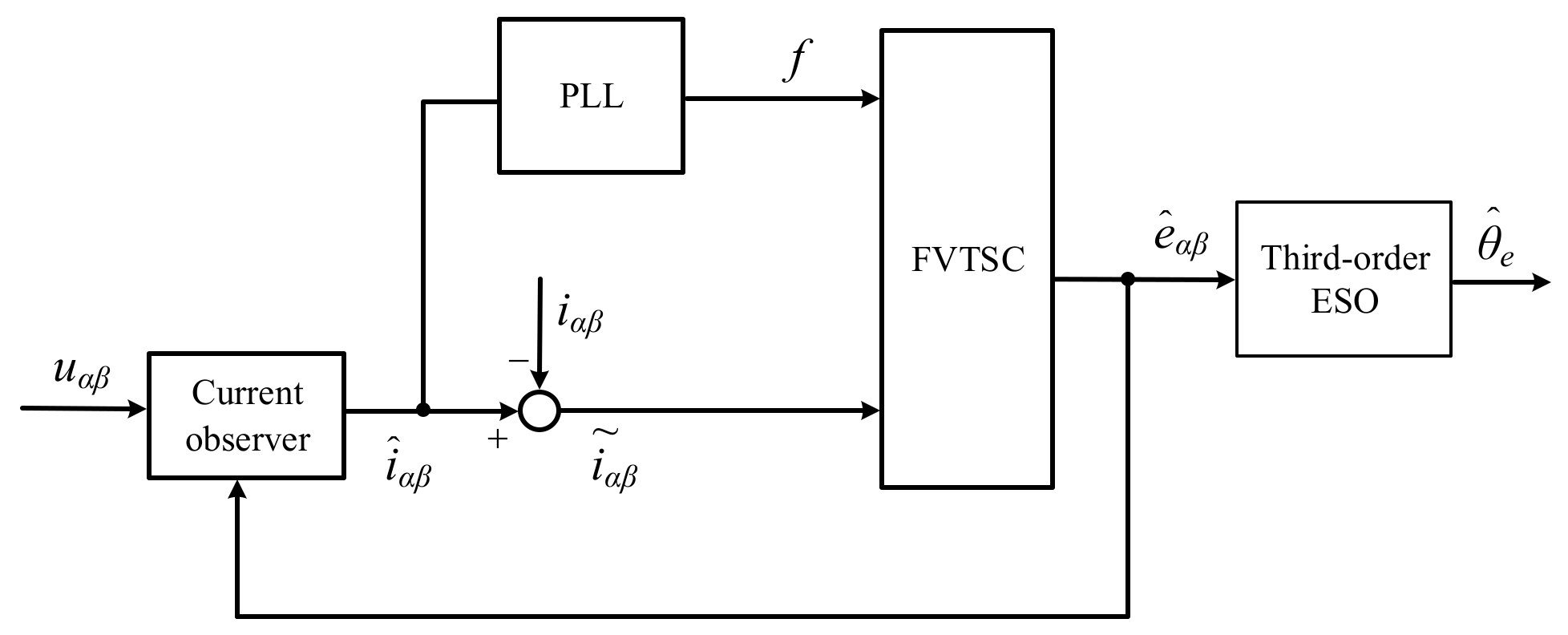
To summarize, the overall implementation block diagram of the new SMO is shown in Figure 7. The estimated stator currents i ^ α and i ^ β are obtained by using the current observer and when compared with the measured values iα and iβ, the deviation values i ˜ α , i ˜ β of the stator current are obtained. Then, the deviation values i ˜ α and i ˜ β , together with the stator current frequency f obtained through the PLL, are input into the FVTSC module to obtain the BEMF. Finally, the rotor position information is obtained through the third-order ESO module.

4. Simulation Study

To prove the effectiveness and feasibility of the new high-efficiency control technology and sensorless position detection technology proposed in this study, a simulation platform of the dual Y shift 30° six-phase PMSM with an isolated neutral point was built, as shown in Figure 8, and simulation studies were conducted. The six-phase PMSM simulation parameters were consistent with the experimental motor. The settings were as follows: R = 0.102 Ω, Ld = 0.82 mH, Lq = 0.82 mH, ψ = 0.072 Wb, P = 3.

4.1. Simulation at Startup Process

The motor started with a 5 N·m load torque and the given rotating speed was set to 500 r/min. Figure 9 and Figure 10 show the rotation speed and position angle waveforms, respectively. The solid red line in each figure represents the estimated rotation speed and position of the rotor, and the dotted black lines represent the actual rotation speed and position measured by the motor. Figure 11 and Figure 12 show the waveforms of the rotation speed error and the position angle error of the rotator, respectively. It can be seen that the speed error was within ±1 r/min and the rotor position angle error within 0.007 rad. The observer can accurately estimate the speed and track the rotor position angle. Figure 13 shows the speed waveforms when the speed was increased from 500 r/min to 1000 r/min. Figure 14 shows the rotor position angle waveforms in the process of the speed increase. Figure 15 and Figure 16 show the rotation speed error and rotor position angle error waveforms in the process of the speed increase, respectively. It can be seen that as the motor speed increases, the motor rotor position error becomes smaller, within 0.03 rad. The effectiveness of the method was verified by simulation.
Figure 17 and Figure 18 show the comparison of the rotor position angle error waveforms obtained by the traditional SMO and the improved SMO at 500 r/min and from 500 r/min to 1000 r/min, respectively. The black line in the figures represents the position angle error obtained by the improved SMO, and the blue line represents the position angle error obtained by the traditional SMO. It can be seen from Figure 17 that the position angle error estimated by the improved SMO was 0.06 rad, and the position angle error estimated by the traditional SMO was 0.2 rad. As the motor speed increased, the motor position angle error estimated by the improved SMO was smaller, within 0.035 rad, as shown in Figure 18. Therefore, the sensorless control algorithm proposed in this paper can estimate the angle of the rotor more accurately.

4.2. Robustness Analysis

According to the working principle of the observer, if the prediction model is not accurate, the robustness of the system will also deteriorate accordingly. In the traditional SMO, the variation of resistance, inductance, and flux will lead to the error of the predicted current which will affect the control performance of the traditional SMO. If the model observer can be improved, the influence of the parameters on the predicted values of the system can be avoided, and the robustness of the system can be improved accordingly. Through tracking the stator current frequency, the FVTSC can detect and compensate the predicted current in real time. When the actual model parameters change, it can make the predicted current track the actual current to increase the accuracy of the prediction.
Figure 19 shows a comparison between the estimated current and the actual current when the winding resistance was rated at 0.102 Ω. Figure 20 shows the current error graphs when the winding resistance was rated at 0.102 Ω.
Figure 21 and Figure 22 show a comparison between the estimated and the actual current waveform when the rated resistance changes by 70% and 130%, respectively. Figure 23 and Figure 24 show the current error graphs when the rated resistance changes by 70% and 130%, respectively. From Figure 19, Figure 20, Figure 21, Figure 22, Figure 23 and Figure 24, the current estimation values based on the observer were not affected when the motor parameters changed, and the current error value was between ±0.1 A, so the robustness of the observer was verified.

5. Experiment Study

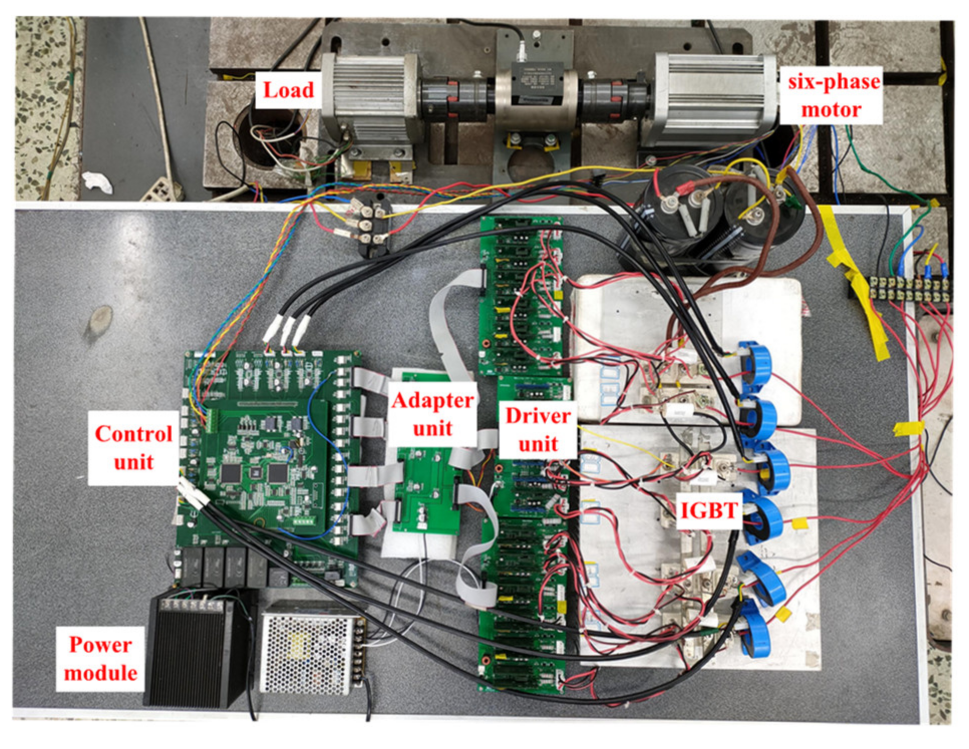
To prove the accuracy and reliability of the six-phase PMSM control strategy in this study, a dual Y shift 30° six-phase PMSM with an isolated neutral point was taken as the research object. The six-phase motor parameters are shown in Table 1. The experimental platform can be seen in Figure 25.
The motor started with a 3 N·m load torque, and the given rotating speed was set to 500 r/min. Figure 26 shows the motor speed and current waveform at 500 r/min, and Figure 27 shows the motor speed and current waveform at 1000 r/min, from 500 r/min to 1000 r/min. As can be seen from Figure 26 and Figure 27, the phase current of the motor has a high sinusoidal degree, and the phase relationship conforms to the theoretical analysis. During the abrupt change of the motor speed, the phase current and rotor speed quickly returned to the steady state.
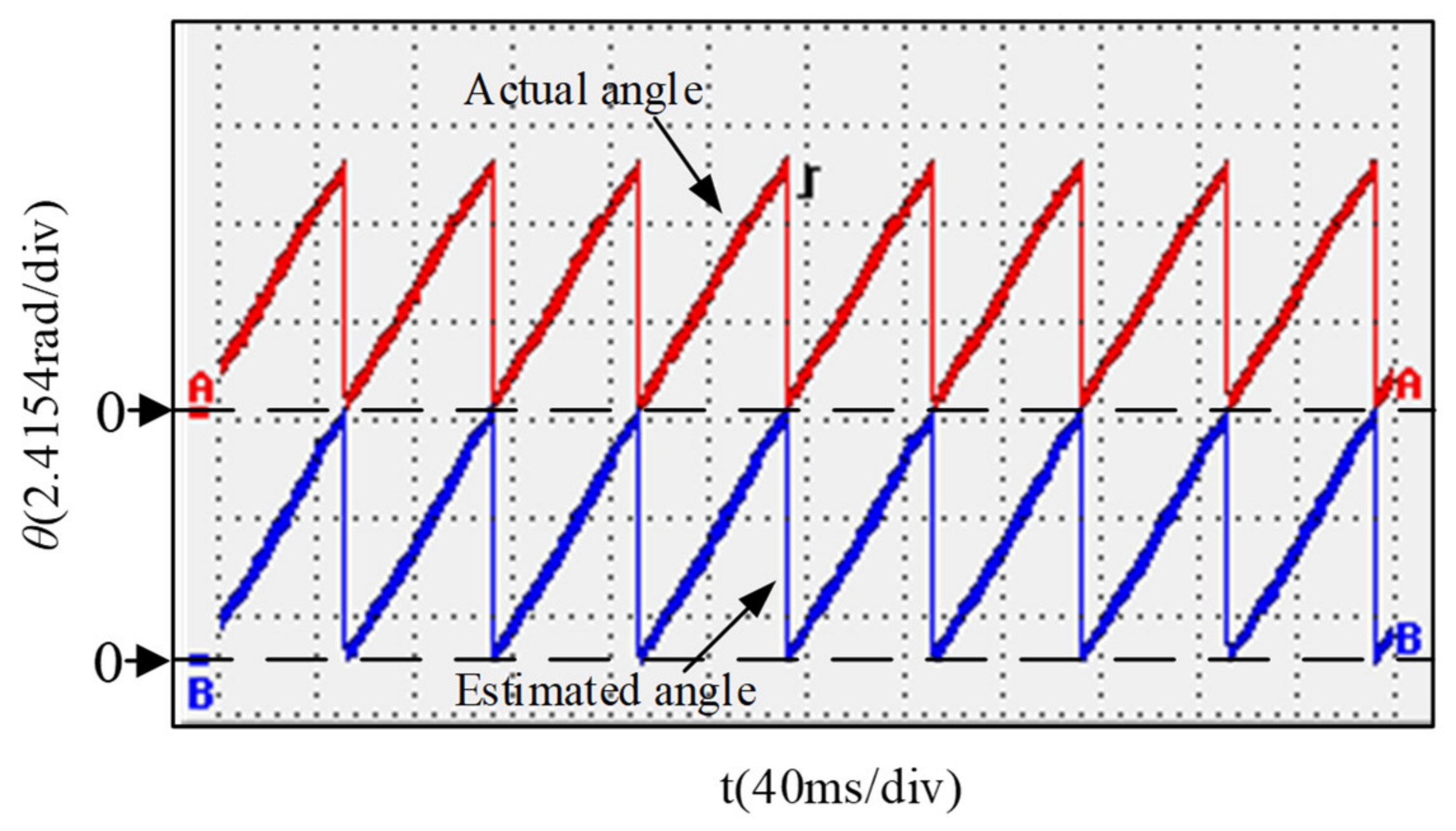
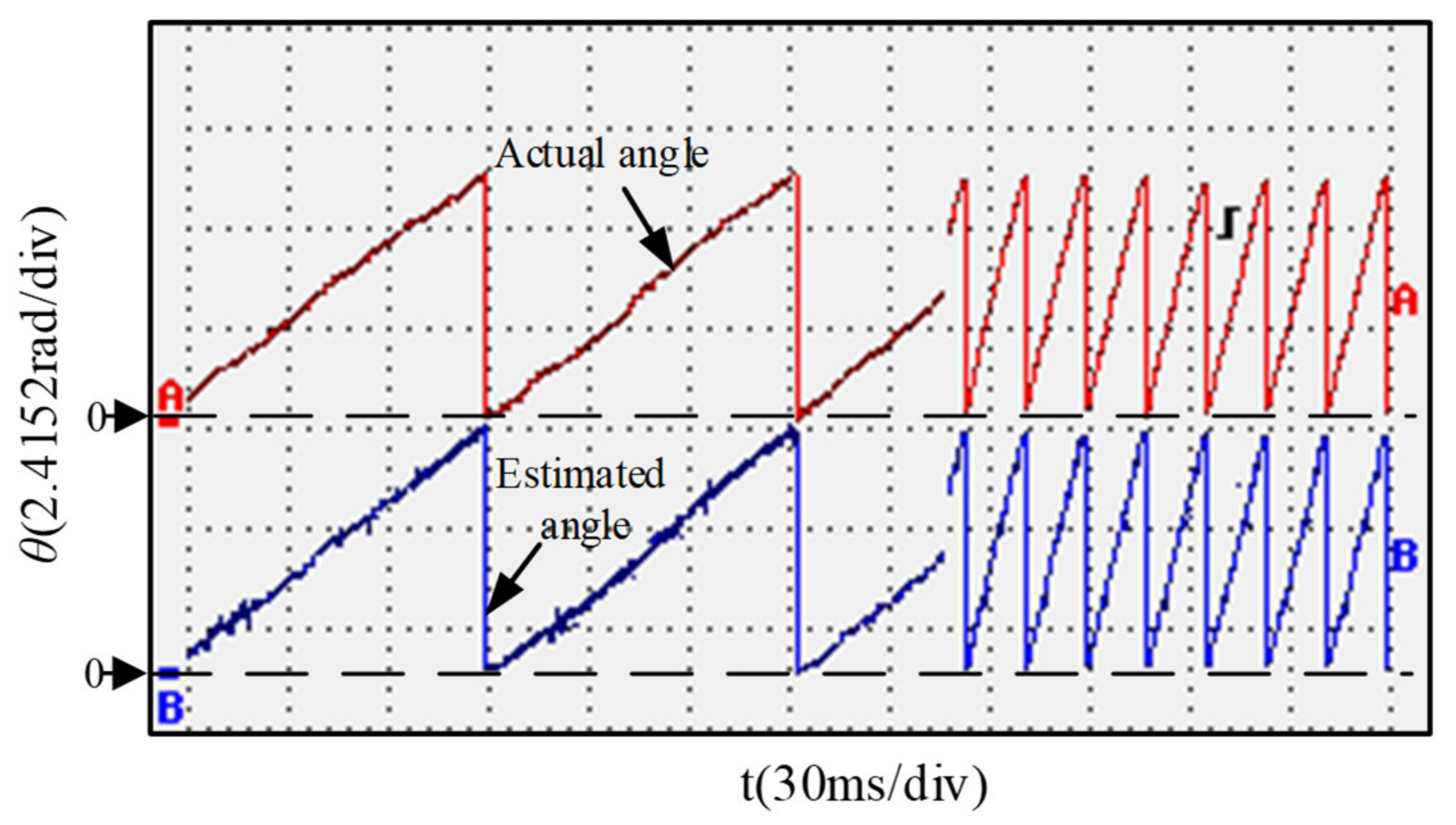
The waveforms of the estimated and actual rotor position of six-phase PMSM under 500 r/min steady-state operation and the experimental waveforms of the motor from 200 r/min to 1000 r/min are shown in Figure 28 and Figure 29, respectively, in which red represents the actual rotor position and blue represents the estimated rotor position of the improved SMO. The rotor position angle error waveforms at 500 r/min and rotor position error waveforms at the sudden change of rotation speed are shown in Figure 30 and Figure 31, respectively. From Figure 28 and Figure 31, we can see that the estimated angle can quickly and accurately track the rotor position, and that the rotor position error was ±0.06 rad, which demonstrated the feasibility of the SMO in this study.

6. Conclusions

In this paper, the mathematical model of the six-phase PMSM was established in the static coordinate system and the traditional sliding mode variable structure controls were improved by combining the FVTSC and the ESO. The problems of chattering, low estimation accuracy of the BEMF, and phase lag existing in the traditional SMO system were solved, and the ability to resist load disturbance was improved. Finally, simulation and experimental research was carried out and the results showed that the new detection and control strategies proposed in this paper could accurately estimate the rotor position, ensured that the motor had good dynamic performance, and the system had strong robustness when the motor parameters changed.
However, this paper ignored the multidimensional characteristics of the six-phase motor system; therefore, any future research directions should also include sensorless detection and control in the case of failure.

Author Contributions

Conceptualization, H.G.; Formal Analysis, H.G. and G.Z.; Data Curation, W.W. and G.Z.; Writing—Review and Editing, W.W. and X.L. All authors have read and agreed to the published version of the manuscript.

Funding

This research work was funded by the National Natural Science Foundation of China, grant number 51177031.

Data Availability Statement

The data presented in this study are available on request from the corresponding authors.

Conflicts of Interest

The authors declare no conflict of interest.

References

  1. Boglietti, A.; Bojoi, R.; Cavagnino, A.; Tenconi, A.; Bojoi, I.R. Efficiency Analysis of PWM Inverter Fed Three-Phase and Dual Three-Phase High Frequency Induction Machines for Low/Medium Power Applications. IEEE Trans. Ind. Electron. 2008, 55, 2015–2023. [Google Scholar] [CrossRef] [Green Version]
  2. Williamson, S.; Smith, S. Pulsating torque and losses in multiphase induction machines. IEEE Trans. Ind. Appl. 2003, 39, 986–993. [Google Scholar] [CrossRef]
  3. Singh, G.K.; Nam, K.; Lim, S.K. A Simple Indirect Field-Oriented Control Scheme for Multiphase Induction Machine. IEEE Trans. Ind. Electron. 2005, 52, 1177–1184. [Google Scholar] [CrossRef]
  4. Barcaro, M.; Bianchi, N.; Magnussen, F. Faulty Operations of a PM Fractional-Slot Machine with a Dual Three-Phase Winding. IEEE Trans. Ind. Electron. 2011, 58, 3825–3832. [Google Scholar] [CrossRef]
  5. Alberti, L.; Bianchi, N. Experimental Tests of Dual Three-Phase Induction Motor under Faulty Operating Condition. IEEE Trans. Ind. Electron. 2012, 59, 2041–2048. [Google Scholar] [CrossRef]
  6. Karttunen, J.; Kallio, S.; Peltoniemi, P.; Silventoinen, P.; Pyrhonen, O. Decoupled Vector Control Scheme for Dual Three-Phase Permanent Magnet Synchronous Machines. IEEE Trans. Ind. Electron. 2014, 61, 2185–2196. [Google Scholar] [CrossRef]
  7. Ting, D.; Fenghui, L.; Li, S. Fault-tolerant method for six-phase PMSM by adjusting phase angle. In Proceedings of the 2017 20th International Conference on Electrical Machines and Systems (ICEMS), Sydney, Australia, 11–14 August 2017; pp. 1–5. [Google Scholar] [CrossRef]
  8. Almarhoon, A.H.; Zhu, Z.Q.; Xu, P.L. Improved Pulsating Signal Injection Using Zero-Sequence Carrier Voltage for Sensorless Control of Dual Three-Phase PMSM. IEEE Trans. Energy Convers. 2017, 32, 436–446. [Google Scholar] [CrossRef]
  9. Barcaro, M.; Faggion, A.; Bianchi, N.; Bolognani, S. Sensorless Rotor Position Detection Capability of a Dual Three-Phase Fractional-Slot IPM Machine. IEEE Trans. Ind. Appl. 2012, 48, 2068–2078. [Google Scholar] [CrossRef]
  10. Wang, G.; Yang, L.; Yuan, B.; Yuan, B. Pseudo-Random High-Frequency Square-Ware Voltage Injection Based Sensorless Control of IPMSM Drives for Audible Noise Reduction. IEEE Trans. Ind. Electron. 2016, 63, 939–944. [Google Scholar] [CrossRef]
  11. Yang, S.-C.; Lorenz, R.D. Comparison of resistance-based and inductance-based self-sensing control for surface permanent magnet machine using high frequency signal injection. IEEE Energy Convers. Congr. Expo. 2011, 52, 2701–2708. [Google Scholar] [CrossRef]
  12. Li, Y.; Wang, G.; Shen, W.; Zhang, G.; Zhao, N.; He, X.; Xu, D. High-Frequency Signal Injection using Extend State Observer for Position Sensorless PMSM Drives. In Proceedings of the 2020 15th IEEE Conference on Industrial Electronics and Applications (ICIEA), Kristiansand, Norway, 9–13 November 2020; pp. 827–832. [Google Scholar]
  13. Scelba, G.; Scarcella, G.; Cacciato, M.; Pulvirenti, M.; Testa, A. Compensation of rotor positon estimation errors in sensorless dual-three phase PMSM drives through back-EMF sensing. IEEE Int. Symp. Sens. Control Electr. Drives (SLED) 2017, 2017, 199–206. [Google Scholar] [CrossRef]
  14. Liu, J.; Zhu, Z. Rotor position estimation for dual-three-phase permanent magnet synchronous machine based on third harmonic back-EMF. IEEE Symp. Sens. Control Electr. Drives (SLED) 2015, 2015, 1–8. [Google Scholar] [CrossRef]
  15. Guo, L.; Parsa, L. Model reference adaptive control of five-phase IPM Motors based on neural network. IEEE Int. Electr. Mach. Drives Conf. (IEMDC) 2011, 2012, 563–568. [Google Scholar] [CrossRef]
  16. Zhu, Z.; Almarhoon, A.; Xu, P. Improved Rotor Position Estimation Accuracy by Rotating Carrier Signal Injection Utilizing Zero-Sequence Carrier Voltage for Dual Three-Phase PMSM. IEEE Trans. Ind. Electron. 2017, 64, 4454–4462. [Google Scholar]
  17. Peng, S.Q.; Song, Y.Y. Sensorless vector control of PMSM based on adaptive fuzzy sliding mode observer. Control Decis. 2018, 33, 644–648. [Google Scholar]
  18. Shen, J.-Q.; Yuan, L.; Chen, M.-L.; Xie, Z. Flux Sliding-mode Observer Design for Sensorless Control of Dual Three-phase Interior Permanent Magnet Synchronous Motor. J. Electr. Eng. Technol. 2014, 9, 1614–1622. [Google Scholar] [CrossRef]
  19. Kumar, K.P.; Rao, B.V.; Kumar, G. Fractional order PLL based sensorless control of PMSM with sliding mode observer. In Proceedings of the 2018 International Conference on Power, Instrumentation, Control and Computing (PICC), Thrissur, India, 18–20 January 2018; pp. 1–6. [Google Scholar]
  20. Saadaoui, O.; Khlaief, A.; Abassi, M.; Chaari, A.; Boussak, M. Position sensorless vector control of PMSM drives based on SMO. In Proceedings of the 2015 16th International Conference on Sciences and Techniques of Automatic Control and Computer Engineering (STA), Monastir, Tunisia, 21–23 December 2015; pp. 545–550. [Google Scholar]
  21. Shao, Y.; Wang, B.; Yu, Y.; Dong, Q.; Tian, M.; Xu, D. An Integral Sliding Mode Back-EMF Observer for Position-Sensorless Permanent Magnet Synchronous Motor Drives. In Proceedings of the 2019 22nd International Conference on Electrical Machines and Systems (ICEMS), Harbin, China, 11–14 August 2019; pp. 1–5. [Google Scholar]
  22. Zhang, T.; Zhuang, X.U.; Jing, L.I.; Yan, H. Enhanced Speed Extraction for Salient PMSM Sensorless Drives Based on A Cascaded Extended State Observer. In Proceedings of the 2018 IEEE International Conference on Electrical Systems for Aircraft, Railway, Ship Propulsion and Road Vehicles & International Transportation Electrification Conference (ESARS-ITEC), Nottingham, UK, 7–9 November 2018; pp. 1–6. [Google Scholar]
  23. Wu, H.; Wu, J.; Sun, Q.; Wang, H.; Zhang, L. A Novel Sliding Mode Observer-based Sensorless PMSM Control. In Proceedings of the 2019 22nd International Conference on Electrical Machines and Systems (ICEMS), Harbin, China, 11–14 August 2019; pp. 1–5. [Google Scholar]
  24. Li, M.; Gu, C.; Li, C.; Wang, X. Control Strategy of Dual Three-phase Permanent Magnet Synchronous Motor Based on Cross Decoupling. In Proceedings of the 2019 22nd International Conference on Electrical Machines and Systems (ICEMS), Harbin, China, 11–14 August 2019; Volume 2019, pp. 1–5. [Google Scholar] [CrossRef]
  25. Yuan, L.; Chen, S.; Wei, K.-Y.; Lin, Y. Current vector decoupling control for six-phase PM synchronous motor considering harmonic current. In Proceedings of the 2018 13th IEEE Conference on Industrial Electronics and Applications (ICIEA), Wuhan, China, 31 May–2 June 2018; Volume 2018, pp. 2565–2568. [Google Scholar] [CrossRef]
  26. Huangfu, Y.; Xu, J.; Zhao, D.; Liu, Y.; Gao, F. A Novel Battery State of Charge Estimation Method Based on a Super-Twisting Sliding Mode Observer. Energies 2018, 11, 1211. [Google Scholar] [CrossRef] [Green Version]
  27. D’Amato, G.; Avitabile, G.; Coviello, G.; Talarico, C. DDS-PLL Phase Shifter Architectures for Phased Arrays: Theory and Techniques. IEEE Access 2019, 7, 19461–19470. [Google Scholar] [CrossRef]
Figure 1. Six-phase inverter topology with double three-phase windings and isolated neutral point.
Electronics 10 01292 g001
Figure 2. Distribution structure diagram of the six-phase PMSM stator windings.
Electronics 10 01292 g002
Figure 3. Stator current frequency detection block diagram based on PLL.
Electronics 10 01292 g003
Figure 4. FVTSC structure diagram.
Electronics 10 01292 g004
Figure 5. Estimation of rotor position information based on the third-order ESO.
Electronics 10 01292 g005
Figure 6. The third-order ESO structure diagram.
Electronics 10 01292 g006
Figure 7. Overall implementation block diagram of the improved SMO.
Electronics 10 01292 g007
Figure 8. Sensorless control system block diagram of dual Y shift 30° six-phase PMSM.
Electronics 10 01292 g008
Figure 9. Speed waveforms comparison at 500 r/min.
Electronics 10 01292 g009
Figure 10. The comparison waveforms of rotor position angle at 500 r/min.
Electronics 10 01292 g010
Figure 11. Speed error waveform at 500 r/min.
Electronics 10 01292 g011
Figure 12. Rotor position angle error waveform at 500 r/min.
Electronics 10 01292 g012
Figure 13. Speed waveforms for increasing speed from 500 r/min to 1000 r/min.
Electronics 10 01292 g013
Figure 14. Rotor position angle waveforms during acceleration process.
Electronics 10 01292 g014
Figure 15. Rotation speed error waveform during acceleration process.
Electronics 10 01292 g015
Figure 16. Rotation position error waveform during acceleration process.
Electronics 10 01292 g016
Figure 17. Waveform comparison of position angle error at 500 r/min.
Electronics 10 01292 g017
Figure 18. Waveform comparison of position angle error in the process of rotating speed change.
Electronics 10 01292 g018
Figure 19. R = 0.102 Ω.
Electronics 10 01292 g019
Figure 20. The current error graphs when R = 0.102 Ω.
Electronics 10 01292 g020
Figure 21. R = 0.0714 Ω.
Electronics 10 01292 g021
Figure 22. R = 0.1326 Ω.
Electronics 10 01292 g022
Figure 23. The current error graph when R = 0.0714 Ω.
Electronics 10 01292 g023
Figure 24. The current error graph when R = 0.1326 Ω.
Electronics 10 01292 g024
Figure 25. Experimental platform.
Electronics 10 01292 g025
Figure 26. Waveforms of the speed and the current.
Electronics 10 01292 g026
Figure 27. The waveforms when the speed changed.
Electronics 10 01292 g027
Figure 28. Rotor position angle waveforms at 500 r/min.
Electronics 10 01292 g028
Figure 29. Rotor position waveforms at the sudden change of rotation speed.
Electronics 10 01292 g029
Figure 30. Rotor position angle error waveform at 500 r/min.
Electronics 10 01292 g030
Figure 31. Rotor position error waveform at the sudden change of rotation speed.
Electronics 10 01292 g031
Table 1. Six-phase PMSM parameters.
ParametersValue
Rated power1.5 kW
Rated speed2000 r/min
Rated voltageAC242 V
Rated frequency100 Hz
Stator resistance0.102 Ω
Ld, Lq0.82 mH
P3
ψ0.072 Wb
Rated current4 A
Publisher’s Note: MDPI stays neutral with regard to jurisdictional claims in published maps and institutional affiliations.

