Article

An Improved User Requirements Notation (URN) Models’ Construction Approach

by
Cyrille Dongmo
1,*,† and
John Andrew Van der Poll
2,†
1
Department of Computer Science, School of Computing, College of Science, Engineering and Technology (CSET), Science Campus, University of South Africa (Unisa), Johannesburg 1709, South Africa
2
Digital Transformation and Innovation, Graduate School of Business Leadership (SBL), Midrand Campus, University of South Africa (Unisa), Midrand 1686, South Africa
*
Author to whom correspondence should be addressed.
These authors contributed equally to this work.
Systems 2023, 11(6), 301; https://doi.org/10.3390/systems11060301
Submission received: 28 April 2023 / Revised: 7 June 2023 / Accepted: 8 June 2023 / Published: 11 June 2023

Abstract

:
Semi-formal software techniques have been very successful in industry, government institutions and other areas such as academia. Arguably, they owe a large part of their success to their graphical notation, which is more human-oriented than their counterpart text-based and formal notation techniques. However, ensuring the consistency between two or more models is one of the known challenges of these techniques. This work looks closely at the specific case of the User Requirements Notation (URN) technique. Although the abstract model of URN provides for link elements to ensure the consistency between its two main components, namely, Goal-Oriented Requirement Language (GRL) and Use Case Maps (UCM), the effective implementation of such links is yet to be fully addressed. This paper performs a detailed analysis of the existing URN models construction process and proposes an improved process with some guidelines to ensure, by construction, the correctness and consistency of the GRL and UCM models. A case study is used throughout the paper to illustrate the suggested solution.

1. Introduction

Mainly due to their graphical modeling approach, which makes them flexible and more human-oriented than, for example, text-based or mathematical-based notation techniques, semi-formal (visual) methods have been very popular [1,2,3]. Most of them allow for the modeling of various system view points at different abstraction levels including, for instance, models specifying user requirements, system and architectural design. With tools providing graphical objects to aid the specification and design of systems, the production of graphical models for the system under development is made relatively easy. However, some of the known challenges are in ensuring the consistency between different models describing the same system and in proposing a bridging mechanism to facilitate the transformation from one model to another. This problem is better understood when taken from the perspective of the model-driven engineering (MDE) approach, where conceptual models are continuously and progressively refined into more detailed ones until the text or code implementing the last model is obtained. Thus, one of the main difficulties being to develop a reusable and traceable transformation process to automatically generate a lower-level model from the more abstract one. In the case of URN, such issue evidently calls for the improvement of the existing (construction) methods. In this regard, this paper aims to address the problem in URN with the purpose of improving its construction process.
URN provides link elements to ensure consistency between GRL and UCM models, and in so doing, the correctness of URN models. To date, and to the best of our knowledge, not much has already been done to reinforce such links at a practical level. In this regard, we found it necessary to re-examine, in as much details as possible, the existing URN construction process focusing on the vertical relationship between GRL and UCM models with the purpose of improving the existing process as well as the quality of the resulting URN models.
The main contributions of this work includes the following:
  • This work performs a detailed analysis of the existing URN modeling process, which is an important step towards the improvement of the process.
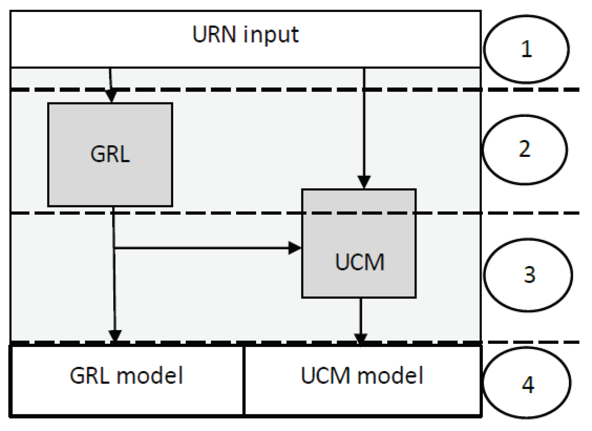
  • We also endeavored to establish the vertical relationship between GRL and UCMs, where a UCM refines an input GRL. This lays the foundation for the development of mechanisms to automate the GRL transformation into a UCM, especially in a model-driven development approach.
  • We propose an improved URN models’ construction process whereby GRL models are constructed independently of UCMs and used as input to UCMs construction. Two algorithms were developed for the improved GRL and UCMs construction processes to facilitate their description and to lay the foundation for their implementation.
The remainder of this paper is organized as follows: Section 2 discusses the related work, and Section 3 presents an overview of the User Requirements Notation (URN). This includes the overview of GRL in Section 3.2, UCM in Section 3.3, and the jUCMNav construction tool in Section 3.4. The existing URN models construction process is discussed in Section 4, followed in Section 5 by an analysis of the process using a case study. Section 6 presents some challenges with the existing URN models construction process, and Section 7 proposes an improved URN process illustrated with a case study. Section 8 presents some pointers for future works and Section 9 concludes the paper.

2. Related Works

Related works can be classified into three categories. The first and the most important category includes the formal specification of graphical models. This category aims mainly to validate or to ensure the correctness of the graphical model [4,5,6]. It has also contributed to resolve the well-known challenge of integrating formal methods into the existing software processes (see for example Abrial [7] (p. 766) and Alagar et al. [8] (Chapter 2)). The second group comprises works pertaining to improve, transform or extend the syntax of the graphical model with, for instance, text-based notations such as XML to facilitate model construction and/or transformation [9,10,11,12]. The last category includes works addressing the concept of refinement, which is very poorly integrated in semi-formal techniques [13,14,15].
Each of the first two categories focuses on validating (or improving the quality of) individual models and hence does not (explicitly) address the relationship between different diagrams. The last category largely addresses the refinement, especially in UML. However, it should be observed that most of these works have each some particularities that distance it from the core problem of this paper. For example, the work by Said [14] involves entities in a UML-B model, which, as formalized elements, ought to naturally adhere to the formal methods refinement rules. Kehrer and Edmund [13] derived (UML) refinement patterns, from the UML template-based refinements, purposing to refine requirements from the elicitation to the analysis and implementation. Although an example of operationalization is given in Java, we failed to figure out how the patterns could, for example, help to analyze and/or establish the refinement relationship between two different models such as Use Case diagrams and class diagrams. In fact, in their conclusion, the authors clearly indicated that the kind of models that could be created by adopting the proposed refinement patterns was still to be investigated.
A similar work by Akhigbe et al. [16] suggests the use of mapping rules to statically link GRL elements to those of UCM. The rules were formalized with OCL and integrated, by means of meta-data, into the main URN tool which is jUCMNav. It is our observation that the main weakness of the mapping rules is the limited flexibility and the broad nature of the proposed rules that map not GRL elements to UCM elements but rather a group of elements (GRL Intentional elements) to another group of UCM sub-maps. At an early phase of software development, the flexibility of the requirements analysis and specification methods or techniques is valuable in the sense that, at such stage, alternative solutions need to be elaborated and evaluated to facilitate decision making.
Sebastián, Gallud and Tesoriero [17] found in their systematic mapping of studies on code generation with the model-driven architecture (MDA) technique that there are few publications regarding the computation independent model (CIM) layer of the MDA showing a research line that may be worth of exploration. In the same vein, this could be an indicator of the challenges faced by software practitioners to develop abstract models to accurately and consistently represent business requirements for the software system. In a survey aiming to understand practitioners’ challenges on Software Modeling, Ozkaya and Erata [18] found that models’ analysis and management are among the primary modeling challenges for software practitioners.

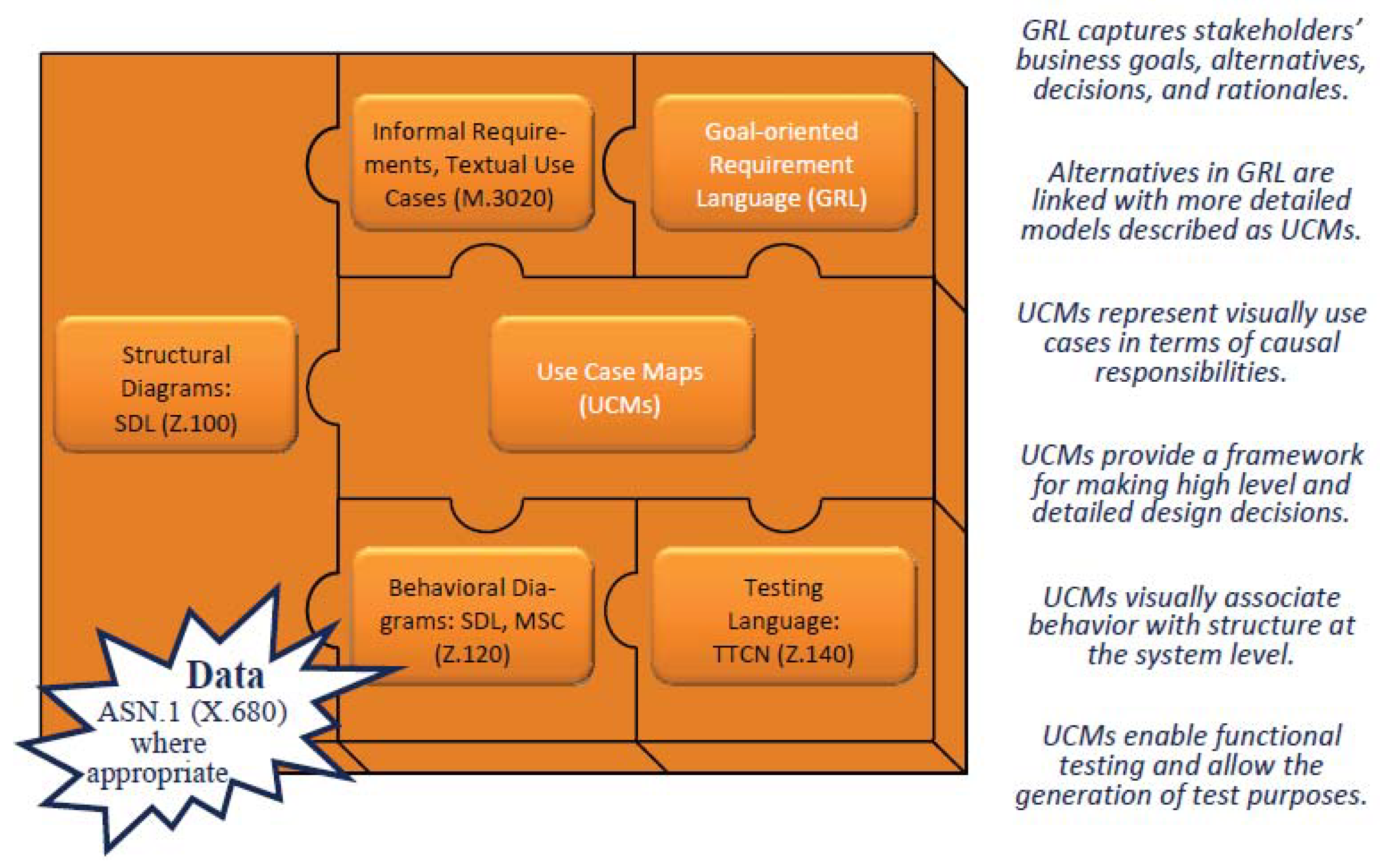
3. An Overview of the User Requirements Notation (URN)

The User Requirements Notation (URN) is a standardized semi-formal, visual, requirements notation that enables the elicitation, modeling and specification, as well as the analysis and validation of user requirements including stakeholder goals [19,20,21]. It comprises two complementary languages: the Goal-Oriented Requirement Language (GRL) and the Use Case Maps (UCMs) [22].

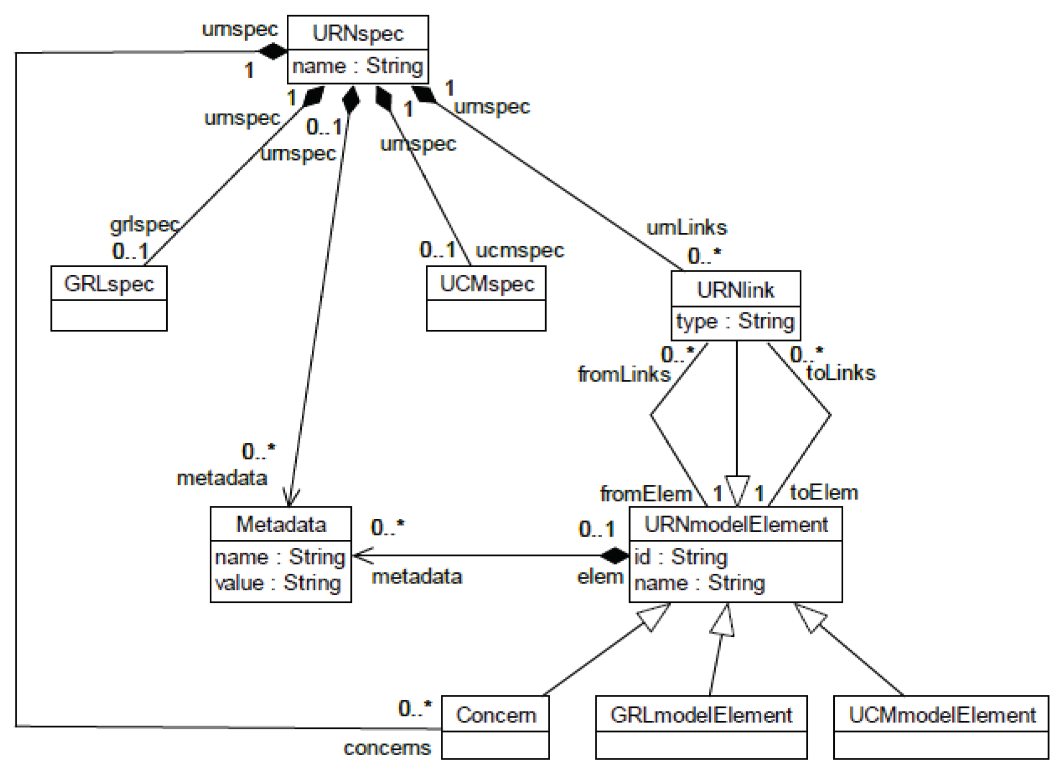
3.1. The URN Meta-Model

The URN basic structural features in Figure 1 describes containers for URN, GRL and UCM specifications [19].
The URN meta-model, namely, URNspec is the root element of the URN specification comprising a GRL specification (GRLspec), UCM specification (UCMspec), URN link elements (URNlink) and meta-data. GRLspec specifies the meta-model for GRL specifications which building blocks are GRL model elements (GRLmodelElement). On the other side, UCMspec specifies the meta-model for UCM specifications. Similarly to GRL specifications, the building blocks for a UCM specification are instances of the UCM model elements (UCMmodelElement). Finally, URNlink is a container for all relationships between URN model elements, especially GRL and UCM model elements. Instances of URN link elements are links connecting URN model elements from one to another.

3.2. The Goal-Oriented Requirement Language (GRL)

The Goal-Oriented Requirement Language, denoted GRL, is a visual modeling notation that aims to address the “Why” of a system at the requirements level, using concepts such as actor, goal, softgoal, task, belief and resource to conceptualize requirements artifacts and the link to establish relationships between those artifacts [19,23,24]. The GRL meta-model from which GRL specifications are constructed (GRLspec) is described in detail in the URN standard document [19]. The GRL model elements are partitioned into two groups: The first includes objects of the class known as GRLLinkableElement, comprising actors’ definitions and intentional elements that are used to model requirements artifacts. An actor specifies an entity that has intentions and may develop strategies to perform their intentions. They are therefore the containers of intentional elements. The second group is formed by objects of the class named ElementLink. They are used to create dependencies between actors, to model the decomposition of intentional elements and to specify the contribution of some intentional elements to satisfy or satisfice other intentional elements. Link elements are important concepts that serve to specify the decomposition, refinement and operationalization of intentional elements.

3.3. The Use Case Maps (UCMs)

The Use Case Map (UCM) is a standardized scenario-based requirements notation technique whose original purpose is to bridge the gap between requirements and design [22,25]. The notation has been very successful due to the use of simple graphical elements to describe, in a map-like diagram, service functionalities superimposed on the organizational structure of complex and distributed systems [26]. A UCM specification is constructed from various model elements, abstracted by the meta-class named UCMmodelElement [19]. The UCMmodelElement constitutes the blueprint for UCMs’ building blocks that include variables, scenarios, resources, components, responsibilities and UCMmap (see Figure 58, URN [19]). The UCMmap meta-model in (Figure 60, URN [19]), is one of the most important building block that combines, by means of node connectors (NodeConnection), most of the UCM elements known as path elements to construct individual UCM maps.
The basic function of a UCM specification is to model and reason about systems functionalities. An important characteristic of UCM is that UCM model elements can be combined in different ways to construct mechanisms that specify different aspects of a system. For example, the And-fork and And-join connectors associated with variables can be used to specify concurrency or parallelism in a system.

3.4. The URN Construction Tool: jUCMNav

jUCMNav is an integrated environment for UCMs and GRL model construction [24,27]. It is a user-friendly graphical editor under the Java-based open-source Eclipse platform. jUCMNav provides, among other functionalities, the support for exporting URN models to external tools and those for importing from external sources. Such facilities allow jUCMNav to communicate with other systems via different types of file formats including XML, MSC (Message Sequence Charts) files and CSM (Core Scenario Model) files. The tool provides for visual link between the two URN models and implements strategies for evaluating GRL models. It equally provides the mechanisms for UCM path traversal (see [28,29]).

4. The URN Models Construction Process

As supported by Liu [23], the basic URN construction process relies on a top-down decomposition strategy. Generally, the higher-level objectives are progressively decomposed and operationalized into more fine-grained conceptual elements to form a graph that constitutes a GRL model. This graph can thereafter be evaluated to establish the level of satisfaction of the initial objectives. Three algorithms have been proposed and implemented for the GRL model evaluation (see [30]). However, one may use any other appropriate evaluation strategy to identify and analyze the elements of the model.
Figure 2 depicts an iterative construction process for URN models [23]. The GRL and UCM models are interactively and iteratively constructed.
The initial requirements in the form of use cases or scenarios, as well as functional requirements (FRs) from the GRL model (mainly the GRL Tasks elements) are represented with UCM graphical symbols to form the initial UCM model. Depending on the expected level of detail, the initial UCM specification is progressively decomposed or refined until a satisfactory level of detail is obtained. The followings sections discuss in more detail the construction of the GRL and UCM models.

4.1. The GRL Model Construction

With GRL, any entity with intentions (e.g., stakeholder), also known as a role-player, is likely to be modeled as an “Actor”. GRL modeling distinguishes two complementary aspects of business objectives or stakeholders intentions: goals describing non-functional requirements (NFRs), namely, softgoals, and goals describing functional requirements, namely, (hard) goals or simply goals. Those two types of goals are developed iteratively, separately and interactively.

4.1.1. Developing Softgoals and (Hard) Goals

Each softgoal is iteratively refined  and operationalized until some concrete design decisions are derived. A softgoal refinement consists to uncover sub-goals required to satisfice the refined softgoal. This is traditionally known as AND/OR decomposition modeled in GRL with decomposition links. A softgoal or goal operationalization is a process that consists to discover operational means necessary to satisfice the softgoal or to achieve the goal being developed. Such operational means include three main GRL intentional elements, namely, tasks, resources and beliefs. Those elements are linked to the developed softgoal or goal by means of GRL link elements. Each such link clearly specifies the nature and type of impact the intentional element will have on the satisfaction of goal being developed [31]. As in the case of softgoals, each goal is decomposed and operationalized until some concrete design decisions are obtained.

4.1.2. Developing Other Intentional Elements: Task, Resource and Belief

Although not explicitly represented in Figure 2, in general, as indicated in the URN standard book, any GRL intentional element can be decomposed and be given a quantitative or qualitative importance [19]. However in practice, the decomposition of GRL Belief elements and, to some extent, the Resources is rarely encountered. On the contrary, the AND/OR decomposition of GRL Task elements is very common. The main purpose of decomposing a task is either to obtain more refined tasks that are easier to implement or to uncover alternative means to implement it.

4.1.3. Connection Points between Softgoals and (Hard) Goals

At any point during the refinement of a softgoal, (hard) goals may be introduced, causing, in the next step, the move from softgoal to (hard) goal analysis. From Figure 2, the shift to UCM construction occurs whenever new architectural design decisions are made.

4.2. The UCM Construction

UCM modeling is an iterative process whereby scenarios’ paths (with path elements such as responsibility points, connections points, etc.) are constructed and bound to components. With complex systems, the initial UCM model is progressively refined until the desired level of detail is obtained. Inputs to UCM are the functional requirements, from the initial requirements, expressed as scenarios, use cases, operations, etc. GRL tasks, resources and beliefs, from the GRL model, constitute in general the most important source of input to UCM.

4.2.1. The Construction of UCM Paths and Path Elements

New input scenarios or use cases generally lead to the creation of new UCM paths or paths segment, whereas an input such as an operation may lead to the update of an existing UCM path or path segment (e.g., by adding a new responsibility point to a path segment). The choice of the UCM element to be added as well as the selection of the path or path segment to be updated are decided by the developer.

4.2.2. Drawing UCM Components and the Binding of UCM Paths to Components

Components are shapes used to represent architectural artifacts such as processes, systems and sub-systems. The ability to bind a UCM path, path segment and path elements to a UCM component renders the construction flexible. Such flexibility allows the practitioner to either specify the scenarios first or to construct the architectural design of the system first and bind the two sub-models only when a satisfactory state is obtained.

4.2.3. Refining the UCM Model

Techniques such as stubbing and layering are provided in UCM to refine the model to reach the desired level of details. During the UCM modeling process, the shift to GRL construction occurs whenever new requirements are discovered (Figure 2). Updating the GRL when a new requirement is discovered is important to avoid modeling requirements that do not contribute to achieving any known goal or softgoal. Such a requirement would possibly introduce inconsistencies between the GRL and UCM models.

The Case Study Description

This case study was adapted from the book by Merx and Norman [32]. Consider a software program that provides voters with the ability to vote in elections using a simple computer-based interface (electronic voting or “e-voting”). The purpose of the program is to make voting more accessible to the general public, given the rapid proliferation of PCs around the world. From the comfort of their home, using the familiar Microsoft Windows interface, voters can securely access ballots and vote their chosen representative or proposition. This case study is first used in the analysis of the URN construction presented in the previous section. In the same vein, the case study is used to illustrate our proposed improved URN construction approach.

5. An Analysis of the URN Construction Process

This section is mainly about the vertical relationship between GRL and UCM models. The question one may ask is: Does one of the models derive from the other? In other words, can one model serve as input to the other? The answer to this question may help to rethink and improve the internal URN process as well as the integration of URN into the existing software processes. To address this question, we proceed by observing and analyzing the URN construction approach discussed earlier in the previous sections. The approach is followed to construct GRL and UCM models for the case study, and in so doing, we illustrate our observations. Our perception of the standard URN construction process is summarized in Figure 3, which is used for argumentation. The focus is on the following construction phases: input to URN, the GRL specification (including an initial UCM sketching), the UCM specification, and the URN outputs: GRL and UCM (final models).
We have subdivided the GRL and UCM construction process into four phase to facilitate the analysis that follows.

5.1. The URN Inputs

Initially, the bulk of the URN inputs includes business objectives and stakeholders’ goals that justify the system in construction and constitute the main inputs to GRL. The initial URN inputs may equally include functional requirements in the form of scenarios, use cases, etc., which are direct inputs to UCM. However, when applying the URN modeling approach to the case study, no input, appropriate for the URN modeling, was readily available, indicating the difficulties to model URN models directly from the initial project idea and/or description. Although URN aims to facilitate requirements analysis, the requirements elicitation phase is not explicitly included in the URN process. The activities of the requirements elicitation phase are comprehensively discussed in [33] (pp. 146–158). In the context of this work, the outputs expected from the requirements elicitation include, among others, the list of stakeholders, stakeholders’ goals and business use cases. To render the case study usable, we have selected some of the desired information from the same source and proposed others to make the case study more suitable for the purpose of its use.

5.2. Stakeholders

We have retained four stakeholders for this study: the voter, the vote officer, the security and the voting subsystem or module, defined as follows:
  • A voter is a person who fulfills the voting requirements related to, for instance, the minimum age, the citizenship, the place of residence, etc. A voter must be registered prior to the voting date.
  • A vote officer ensures the good functioning of the voting system, the voting environment and the respect by all actors of the rules and regulations surrounding the voting process.
  • A security company ensures the safety of the physical resources needed for the system.
  • The system includes the hardware and software with all the desired functionalities.

5.3. Stakeholders’ Goals

In practice, each stakeholder would like the system in construction to achieve specific goals. One of the activities of the requirements elicitation and analysis phase is to identify, classify, eliminate duplicates and prioritize such goals. The following goals are considered for the case study:
  • A voter would probably like the system to be easy to use and to preserve the privacy of the voters. For example, it should not be possible for any user to identify and recognize the choice of a any voter.
  • On the other hand, the vote officer is more concerned about the security of the entire system.
Next, we also present a few selected activities of the organizations, namely, business use cases represented in URN as Tasks.

5.4. Business Use Cases

The two business use cases considered are voter authentication and the voting process.

5.5. The URN Model of the Case Study

The GRL and UCM models obtained by applying the standard URN process to the case study are represented, respectively, in Figure 4 and Figure 5.
The process allows for the two models to be constructed simultaneously and interactively. During the construction, goals are passed as inputs to GRL, whereas inputs describing functional requirements are passed to both GRL and UCM and are therefore likely to be processed concurrently in both GRL and UCM. This is particularly the case for use cases or scenarios that are used in GRL to operationalize goals and constitute the main inputs to UCMs. For instance, with the case study, the Authentication operation is used in the GRL model to operationalize the softgoal named Software security (see Figure 4). The use case is specified in the UCM model with two scenario path segments. The first starts with the starting point labeled voter password and ends with either of the two endpoints, Password accepted or Password denied. The second starts with the starting point, Voter biometric, and ends with either of the two endpoints, Biometric accepted or Biometric denied.
As commonly accepted, a software product is developed and used to achieve business objectives that indeed justify the requirements of the system (see e.g., [34]). With regard to the feasibility study, this is formulated as a question by Sommerville, does the system contribute to the overall objectives of the organization? [33]. However, in the current URN construction process, we have no guarantee that direct inputs to UCM are effectively going to be processed in the GRL model to refine or operationalize any goals that ought to justify them. Furthermore, processing the same URN input, independently in GRL and UCM, is a risky activity likely to create inconsistencies in the final URN models. For instance, an input operation directly specified in UCM may be replaced in GRL with a more prioritized task when used as alternative means to achieve a goal.
In the GRL model in Figure 4, both the biometric and password authentication are used as alternative solutions to operationalize the Authentication goal. Meaning that one of the two alternatives should be chosen as the operational mean to achieve the goal. However, the two solutions were readily specified in UCM due to the fact that Password authentication was readily available as input and passed to UCM before the GRL model was constructed.

5.6. Observation on GRL and UCM Models’ Construction

As shown in Figure 2, the GRL softgoals’ and goals’ refinement and operationalization produce operational elements (actors, tasks, resources, beliefs) that constitute inputs to UCM. The UCM modeling process transforms those inputs into architectural artifacts, scenario paths or path segments including responsibility points, path connectors, etc. Condition variables are also used to capture additional information (prose description) wherever necessary. In the UCM modeling process, when a new requirement is discovered, the process starts the GRL specification of the newly discovered goals and/or softgoals. The bridging from the UCM specification to GRL whenever a new requirement is discovered indicates the intention to keep both GRL and UCM complete and consistent. However, a number of questions also arise. Does the bridging from UCM to GRL imply that all inputs to URN should first be specified in GRL? If not, then one may be tempted to ask: Why is the direct UCM specification of URN inputs allowed? As depicted in Figure 3, the construction of the GRL model normally precedes that of UCM. This is mainly due to the fact that most of the inputs to UCM are obtained from the constructed GRL model. Hence, only a small portion of the UCM specification is actually constructed in parallel with GRL. In the subsequent sections, we argue that some inconsistencies in the URN models are generated during the parallel construction of its two sub-models.
Conceptually, UCM elements should be traceable from those of GRL. For example, for a UCM component or actor, path or path segment, responsibility, etc., it should be possible to point out a GRL element from which it was generated. However, this is not generally the case because, during the UCM specification, there is no information associated to the input element to indicate its origin, that is, whether it operationalizes a goal or a softgoal in a GRL model. This is further complicated by the fact that, although GRL and UCM are all parts of URN, they were designed with the possibility for one to exist without the other. Therefore, the discussion in this paper is conducted under the assumption that the two models of URN are used to develop the same system.
Going back to the analysis of the relationship between GRL and UCM, it is equally important to note that some specific grouping of UCM elements (structuring), including the binding of paths and paths elements to some components, ought to be justified by the need to satisfy some goals or softgoals from GRL. For example, parallelism may be introduced into a UCM map to achieve performance. However, when such a re-structuring action is performed, there is nothing in the UCM model to justify the action, thus making it difficult to link the action back to the softgoal in the GRL model that ought to be achieved.

5.7. Analysis of URN Outputs

The URN outputs include the GRL and UCM models. Although not formally proven, based on the above observations, we believe the UCM model to be a refinement of the GRL model. Assuming some of the UCM elements cannot be linked to any element of the GRL model, one may rightfully ask: Why would a software engineer model functionalities that do not support the business objectives? It is also important to note that the standard URN process in Figure 2 does not include the GRL model evaluation. This is probably because the process was proposed prior to the publication of the most recent URN reference document that defines GRL strategies and model evaluation [19].

6. Some Challenges with the Standard URN Process

From the above analysis of the standard URN process, a number of challenges and/or risks, including the risk of inconsistency, the traceability problem, omission of relevant requirements as well as the specification of irrelevant requirements, are perceptible.

6.1. Inconsistency between the GRL and UCM Models

The consistency problem in URN models has already been well demonstrated by Akhaide et al. [16], who proposed mapping rules to relate GRL components to those of UCM. This work focuses mainly on the source cause of the inconsistency. As discussed in Section 6.4, the GRL model is at a higher abstraction level than UCM. Thus, the concurrent construction of GRL and UCM is a risky approach that can cause a number of threats to the quality of the final URN models, among which are the inconsistencies between the GRL and UCM models. For instance, in the UCM model of the case study in Figure 5, the two solutions for the security requirement are specified. On the other hand, in the GRL graph in Figure 4, the two solutions are alternative tasks for which only the best has to be considered. The problem arises because the password authentication, a business use case, is one of the URN inputs and, due to the concurrent construction approach, was specified in UCM without consideration of the GRL processing of the same input.

6.2. Traceability Problem

Inconsistencies in two or more models is an indicator of the difficulties to link some elements of the more detailed or refined model to those of the abstract model. As discussed in the previous section, having the password and biometric authentication specified altogether in the UCM model not only creates confusion in the system, but also makes it difficult to trace down to the implementation level, which is a means to satisfice the security goal. Furthermore, the testing and validation of the final software product is equally affected as if the problem is not detected at the UCM modeling phase; it may be easily propagated to the subsequent development phases. In the URN process, when a new requirement is discovered in UCM, the GRL model is updated accordingly. However, it is important to notice that, in some cases, the influence of non-functional requirements may be more subtle. A few examples to illustrate include the following:
  • Parallelism may be introduced into a UCM to address a performance requirement specified in GRL as a softgoal.
  • Stubs or layers may be needed in UCM to respond to a security requirement represented in GRL as a goal or softgoal. For example, to group together those functionalities that require a certain level of security.
  • Some elements of a UCM may need to be re-arranged in a certain order to facilitate for example the usability of the system.
These examples show how non-functional requirements in GRL can induce actions (performed on UCM) that do not necessarily describe functional requirements represented physically in the original GRL model. Additionally, UCM elements such as forks, stubs or layers used in the above examples are not (conceptually) different from those created when specifying functional requirements. Thus, there exist the difficulties to trace them back to the original non-functional requirement and, consequently, the difficulty to validate the final UCM model relatively to GRL.

6.3. Specification of Irrelevant Requirements

As pointed out in Section 6.1, specifying two or more alternative requirements in UCM for which only one or fewer need to be selected, introduces in the system irrelevant requirements. This can become a very serious problem in complex systems with a large number of requirements or critical systems for which a small mistake can lead to adverse consequences.

6.4. The Vertical Relationship between GRL and UCM Models

The meta-class URNlink (see Figure 1) specifies an important concept that introduces the relationship between GRL and UCM elements. It allows URN modelers to think, among others, about the traceability, refinement and composition between the objects specified in the GRL and UCM models. Such a relationship is further illustrated in Figure 6.
To the best of the authors’ knowledge, before the OCL implementation of mapping rules [16], the implementation of URNlink was limited to a visual connection between the model elements of GRL and UCM. As discussed in the previous section, this brings forth the importance to investigate the extent to which UCM elements can be traced back to GRL ones.
From URN construction, it appears that each UCM element is linkable to GRL operational element(s) (principally, actors’ definitions, tasks, resources and beliefs) that collectively contribute to satisfy GRL goals and softgoals. This is justifiable since GRL operational elements representing functional requirements are directly specified in UCM as can be observed in Figure 6.

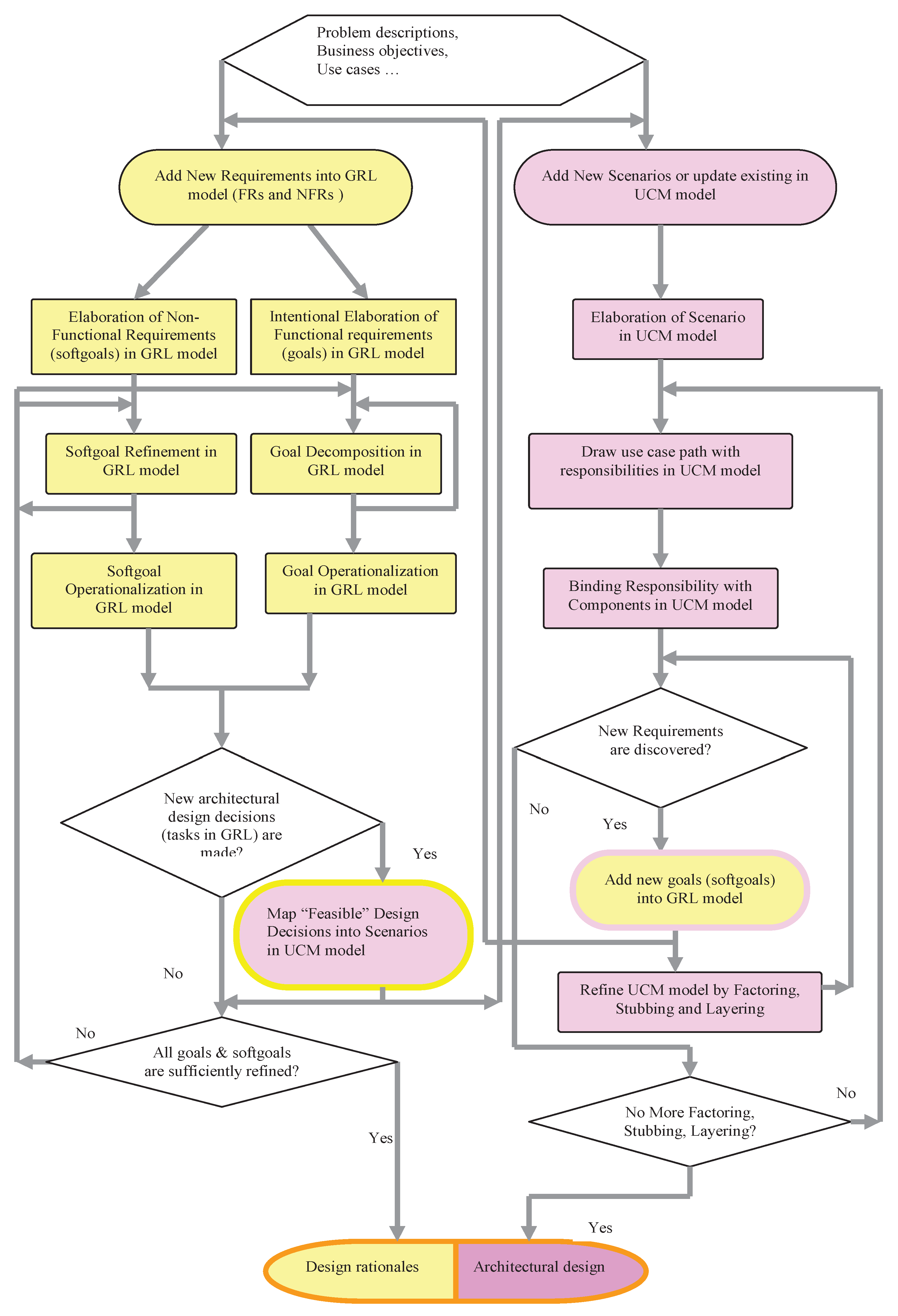
7. An Improved URN Process

In the previous section, we argued that some problems in the URN models, notably, the inconsistency and non-traceability, are due to the URN construction process, especially when the two URN models are developed concurrently or when the UCM model is developed before the goal model. Although we cannot yet make a rigid conclusion regarding the vertical relationship between GRL and UCM, we have at least provided convincing elements to show that a UCM model is at a lower abstraction level than the GRL. This is further supported by the fact that, from the current URN process, most UCM inputs are obtained from the GRL model. Therefore, to correct some of the limitations of the current process and, in so doing, improve the quality of the URN models, we propose in this section an improved version of the URN construction process. This involves a three-step approach with an improved GRL model construction, namely, the bridging approach to facilitate the UCM specification of an input GRL model and an improved UCM model construction.

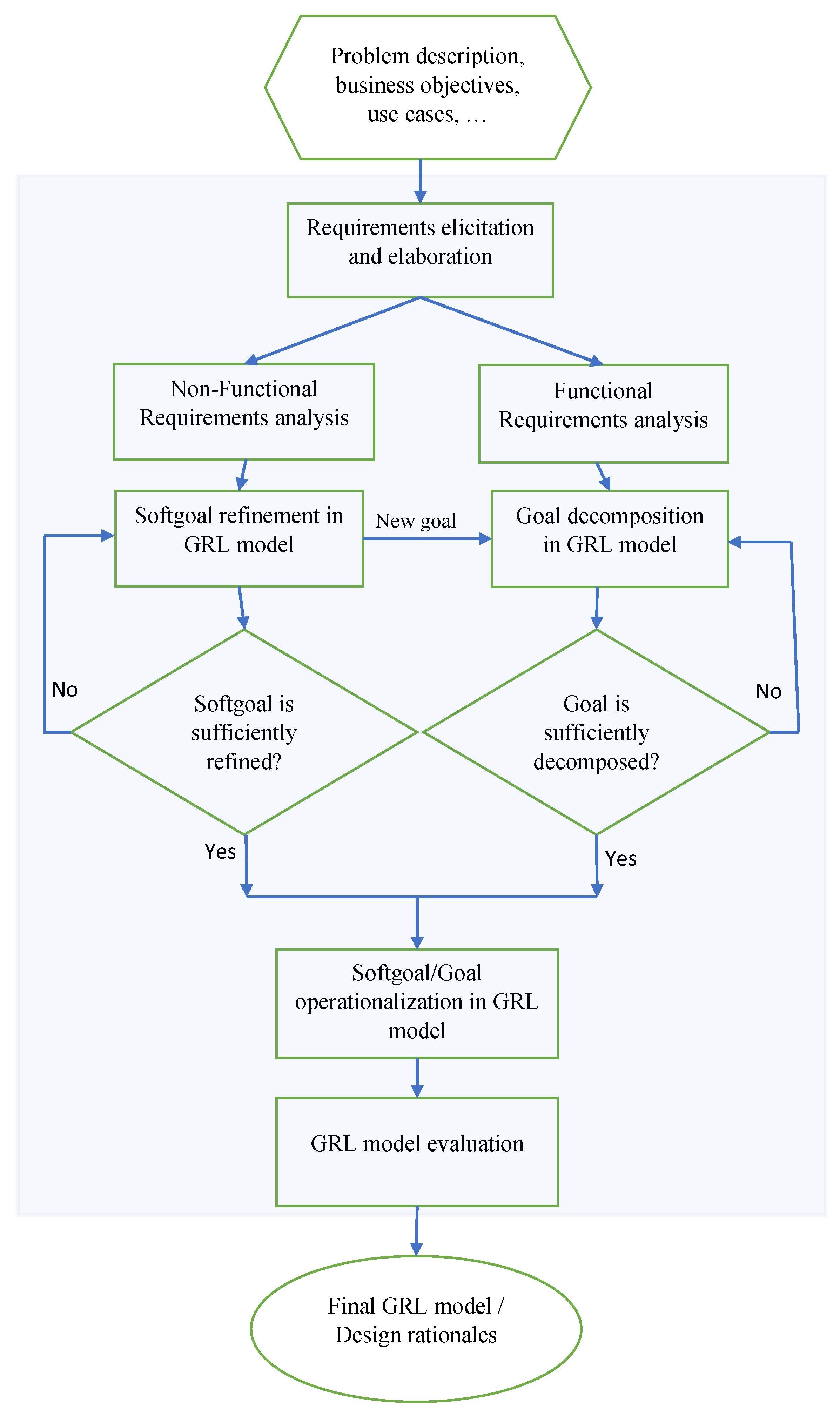
7.1. The Improved GRL Model Construction Process

Our proposed GRL process, illustrated in Figure 7, is based on the current URN process in Figure 2, the main difference being that the process is now an independent module, with two added tasks, that can be implemented, manipulated and/or updated independently of any other part of the URN process. With an appropriate bridging method, the process can be linked to any other existing software methods or process not necessarily related to URN.

7.1.1. Process Description

The inputs to the proposed GRL model construction are the same as those in Figure 2. We have added the “Requirement elicitation and elaboration” phase in the process. As discussed earlier, in practice and in most cases, the initial project description provides very little information to enable the system developer to proceed directly with the requirements specification. Thus, the necessity for this phase to explicitly proceed with the requirements elicitation during which proper inputs to GRL are identified, analyzed and categorized into, for instance, non-functional and functional requirements. Thereafter, the analysis of non-functional and functional requirements can be performed followed by softgoals and goals refinement and operationalization.The last step of the process is the GRL model evaluation, whereby, based on the chosen strategy (e.g., [31]), alternative solutions to softgoals and goals satisfaction are generated. Algorithm 1 summarizes the process and therefore constitutes the first step toward its formalization.
Algorithm 1: The improved GRL construction algorithm
Systems 11 00301 i001

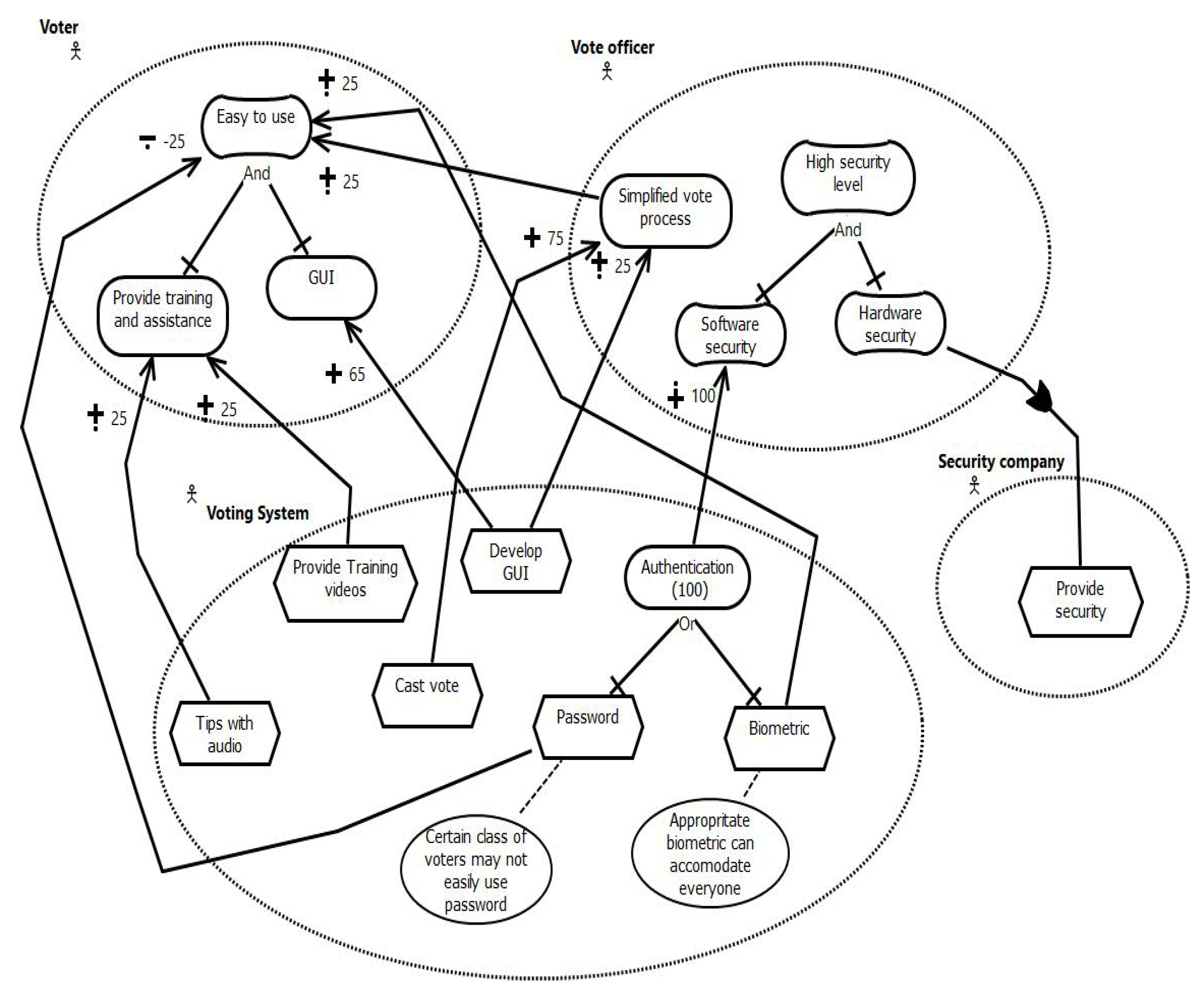
7.1.2. The GRL Model of the Case Study

The GRL model of the case study obtained by applying the proposed GRL modeling process is represented in Figure 8. Knowing that the GRL model construction mainly depends on the developer’s analysis of the inputs and is therefore far from being a deterministic process, we follow the line of thinking used to produce the model in Figure 4 and avoid going into detail when refining and operationalizing the softgoals and goals. The detailed refinement of goals would very likely lead to differences that may not be related to the process but rather to the alternative perceptions or views of the problem by the developer that may arise during detailed analysis of possible solutions.

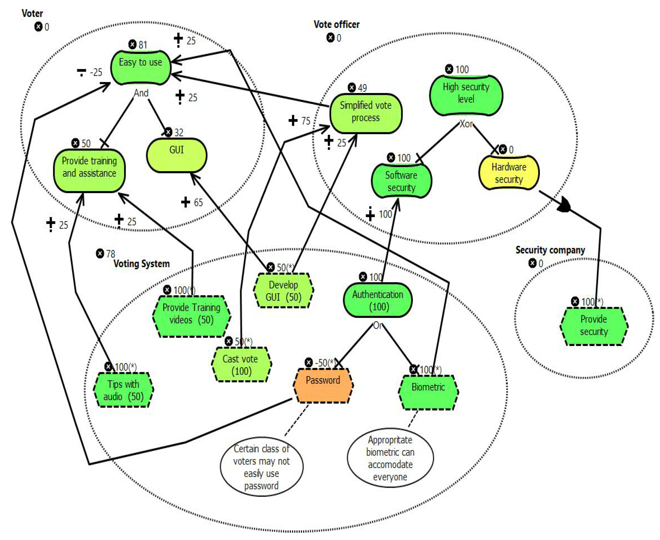
7.1.3. Presentation and Analysis of the GRL Model of the Case Study

As mentioned earlier, the GRL modeling process is not deterministic, and so, with the same inputs, different developers may very likely produce models with some differences. It is therefore important to consider, in addition to the output, the views of the developer. That is why we strove to keep the model as simple as possible. In both cases where the current and the proposed URN processes were applied to generate the resulting models, respectively in Figure 4 and Figure 8, the GRL elements describing the intentions of each of the actors were included in the actor’s definition. The relationships between elements in different actors were limited to the essentials. Such relationships require a more detailed analysis of the system and hence are likely to introduce in the model elements that may depend more on the developer’s perception of the problem than the process. With this limitation, the two models are exactly the same. The two models might have been different if the same outputs from the elicitation phase were not used in both processes.
From the initial requirements, the voter’s intention is for the system to be easy to use which is specified as a softgoal, named easy to use in the GRL model. The two goals of the “Vote officer” are to have a simplified voting process and a highly secured system. In the refinement and operationalization phase, the analysis of the goals, which is relatively subjective as depends highly on the developer’s judgment, results in the following:
  • Easy to use is decomposed into two complementary sub-goals: the first is GUI; having a system with a graphical user interface would contribute to rendering the system easy to use. The second goal is to Provide training and assistance by making training videos, as well as online tips with audio instantly accessible to users. Hence, we (the developers) are convinced that the system would be easy to use if the three tasks, including the development of a graphical user interface, are altogether successfully implemented. A different developer with more or less knowledge of the field, user experience, existing tools, etc. may have a different understanding of the softgoal and, hence, a different solution.
  • Having a Simplified vote process as intended by the vote officer would also contribute to making the system easy to use. In return, developing a GUI in addition to the way people cast votes would help to simply the voting process.
  • Another concern of the vote officer is for the entire system to be Highly secured. This softgoal is decomposed into two complementary sub-softgoals: the Software security and the Hardware security, which depends on a security company to ensure the safety of the physical equipment. The software security is achieved through user Authentication. A user can be authenticated by means of biometrics or a password.
    The belief that a certain class of voters may not easily use a password is in favor of the biometric solution.
The initial quantitative values were allocated to some elements mainly to render the evaluation of the final GRL model possible. However, some light justifications can be provided in some cases. For instance, based on the two beliefs that “a certain class of voters may not easily use password” and that “Appropriate biometric can accommodate everyone”, a higher quantitative value was allocated to the biometric authentication. This could be different if the cost associated to each alternative solution was considered. After the evaluation of the GRL model, based on the color of each element, namely, dark green for the most prioritized alternative (in color printing) or simply the darkest (in black and white printing), it appears, for instance, that the software security and the biometric authentication are chosen over other alternatives. The evaluated GRL model is shown in Figure 8. If this model is the selected one, then the password authentication will not be considered in subsequent models as the chosen solution for user authentication is the biometric authentication.

7.2. Preparing a GRL Model for UCM Specification

Despite the incontestable contribution of GRL to the analysis of functional and non-functional requirements abstracted with the concepts of goals and softgoals, one of the limitations of the approach is the difficulty for a GRL model to serve as input [36]. Although such difficulties maybe alleviated when applying GRL models to UCM specification, as they both share the same tool support and are parts of the same standardized notation, for the purpose of modularity and maintenance, it is important to have a bridging subsystem between them. The main purpose of the subsystem would, for instance, be to traverse the input GRL model and generate the information necessary for UCM modeling and ensure traceability between the two models. We found it important to introduce the subsystem; however, the full development of the system is outside the scope of this paper.

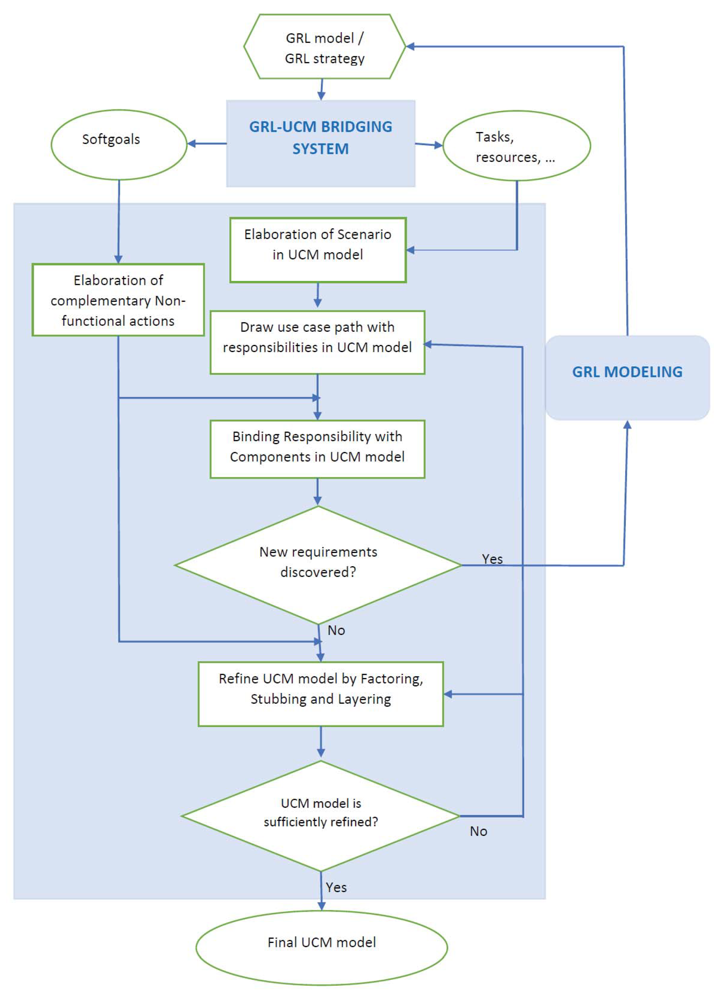
7.3. The Improved UCM Model Construction Process

In the first place, the proposed UCM modeling process is an independent process that accepts as inputs generic tasks, scenarios, use cases and resources. Such inputs may be generated directly from a GRL model or any other source. We have also made it possible to have softgoals describing non-functional requirements as input. This may seem unusual but not surprising because, for instance, since its creation, UCM has long been used for early performance analysis of complex systems [37]. UCM has always been an independent process since its creation and this was the case with the early UCM tool, namely, UCMNav [38], as well as the most recent and current tool, jUCMNav [28,29]. The proposed UCM process is represented in Figure 9 and discussed in the subsequent section.

7.3.1. The UCM Process Description

The discussion on the proposed UCM process is conducted from the perspective of addressing the consistency problem in the URN. In this regard, the UCM modeling is performed with consideration of the GRL model, from which inputs to UCM are generated. The entire process is depicted in Figure 9. The intermediary sub-system, named GRL-UCM Bridging system, is intended to be a plugin (or added functionalities to the existing tools) whose main purpose is to scan the input GRL model or part of it to generate all the information needed for the UCM modeling, as well as information necessary to ensure the traceability between the resulting UCMs and the input GRL model.

7.3.2. The Processing of the Standard Inputs

The commonly known inputs to UCM are generic tasks, describing functional requirements, from a GRL model. GRL actors and resources are equally used in the UCM specification. In the same vein, use cases or scenarios are also direct inputs to UCMs. However, the processing of GRL tasks requires, in most cases, more effort for their analysis than use cases and scenarios. Thus, there is necessity for the scenario elaboration phase during which tasks and use cases are analyzed in detail to produce detailed scenarios and alternatives. This analysis enables the drawing of use case paths and path segments with all the other necessary path elements such as start points, responsibility points, end-point, etc. in the next step. In addition, the analysis of other inputs such as GRL actors and resources stimulates the drawing of architectural components and the binding of paths and path segments to them. In practice, there is no prescribed order in the drawing of components and use case paths. The processing of softgoals in UCM intervenes after the first draft of UCMs is completed.

7.3.3. The Processing of the Input Softgoal

As illustrated in Section 6.2, a number of actions performed on the model in construction are essentially conducted with the implicit intention to achieve non-functional requirements and so to improve the quality of the model. The fact that such actions are generally not documented further complicates the traceability and consistency problems. To address this issue, we propose to formally process softgoals in UCMs. The idea is to continuously perpetrate the impact of NFRs into intermediate models throughout the software life cycle until the final product is built. The development of softgoals in UCM is based essentially on the concept of Complementary Non-Functional Actions (CNF-Actions), introduced by Dongmo [39] (pp. 62–66).
A CNF-Action is an abstraction of any action performed on an intermediate model to achieve a softgoal describing an NFR in addition to the initial analysis performed in GRL. In Figure 9, the “elaboration of the complementary non-functional actions” consists to identify for a given softgoal the possible actions that can be performed on the UCM in construction. The common characteristics of CNF-Actions are that they are generally applied, not on individual element but on a subset or the entire UCM model. For example, they can be used to guide the binding of scenario paths to architectural components, as well as the re-structuring and refinement of the initial UCMs or part of it.

7.3.4. The Processing of a New Requirement

When a new requirement is discovered, it is recommended to first develop the requirement in GRL to ensure consistency between the input GRL model and the UCMs in construction. This recommendation is relevant only when inputs to UCMs are extracted from an input GRL model. The bridging from UCM modeling to GRL is relatively easy because the two models are constructed with the same tool support, jUCMNav. However, it would require more effort if the two models rely on different construction tools, for instance, when constructing a UML model from a GRL specification.

7.3.5. The Iterative Nature of the Process

The UCM and GRL models construction is inherently iterative. With the UCM model for instance, the drawing of scenario paths, path segment, architectural components as well as the binding of scenario paths or path segments to the components is repeated for each input, including new requirements discovered during the construction, which are first analyzed in GRL. In the same vein, the refinement of the initial UCM model, which is triggered by the desire for more details and the need to continuously perpetrate the influence of NFRs into the model for the purpose of quality improvement or any other reason, is repeated for each input softgoal or until the expected level of details is obtained. The process is summarized in Algorithm 2.
Algorithm 2: The improved UCM construction algorithm
Systems 11 00301 i002

7.3.6. Traceability with Trace Operations

When a GRL model is used as input to UCM, each GRL element to be specified in UCM is known even beforehand. This makes it possible to create an appropriate data structure to keep a record that relates each GRL element to UCM elements used in its specification. It may also keep records of actions performed on the UCMs to further achieve an input softgoal. Such a data structure permanently saved in a file should be continuously updated during the UCMs construction process until the final model is produced. Thus, the functionalities to update the file, export it to other platforms and retrieve needed information from the data structure also have to be implemented. The main purpose of the trace operations is to make it possible for developers, at different software development phases, to trace back, for each UCM element, the input GRL element being specified, or to identify, for each input GRL element, the UCM elements used to specify it. In the same vein, it would provide information on CNF-actions performed on the UCMs to achieve or further satisfy an input softgoal. Trace operations, if successfully implemented, would facilitate the validation of a UCM model relatively to the input GRL.

7.3.7. The Resulting UCMs

The final UCM model is produced when new requirements are all processed and the model is sufficiently refined or the expected level of detail is obtained. The UCM model of the case study is represented in Figure 10 and discussed in the next section. The model is at a relatively higher abstraction level to facilitate the comparison with the UCM model in Figure 5.

7.4. The Application of the Proposed UCM Process to the Case Study

In this section, the case study described on Section 4.2.3 and Section 5.1 is used to illustrate the improved UCM process discussed in the previous section. The resulting UCM model is compared to the one obtained from the same case study by applying the process in Figure 2 in order to identify possible improvements due to the proposed process.

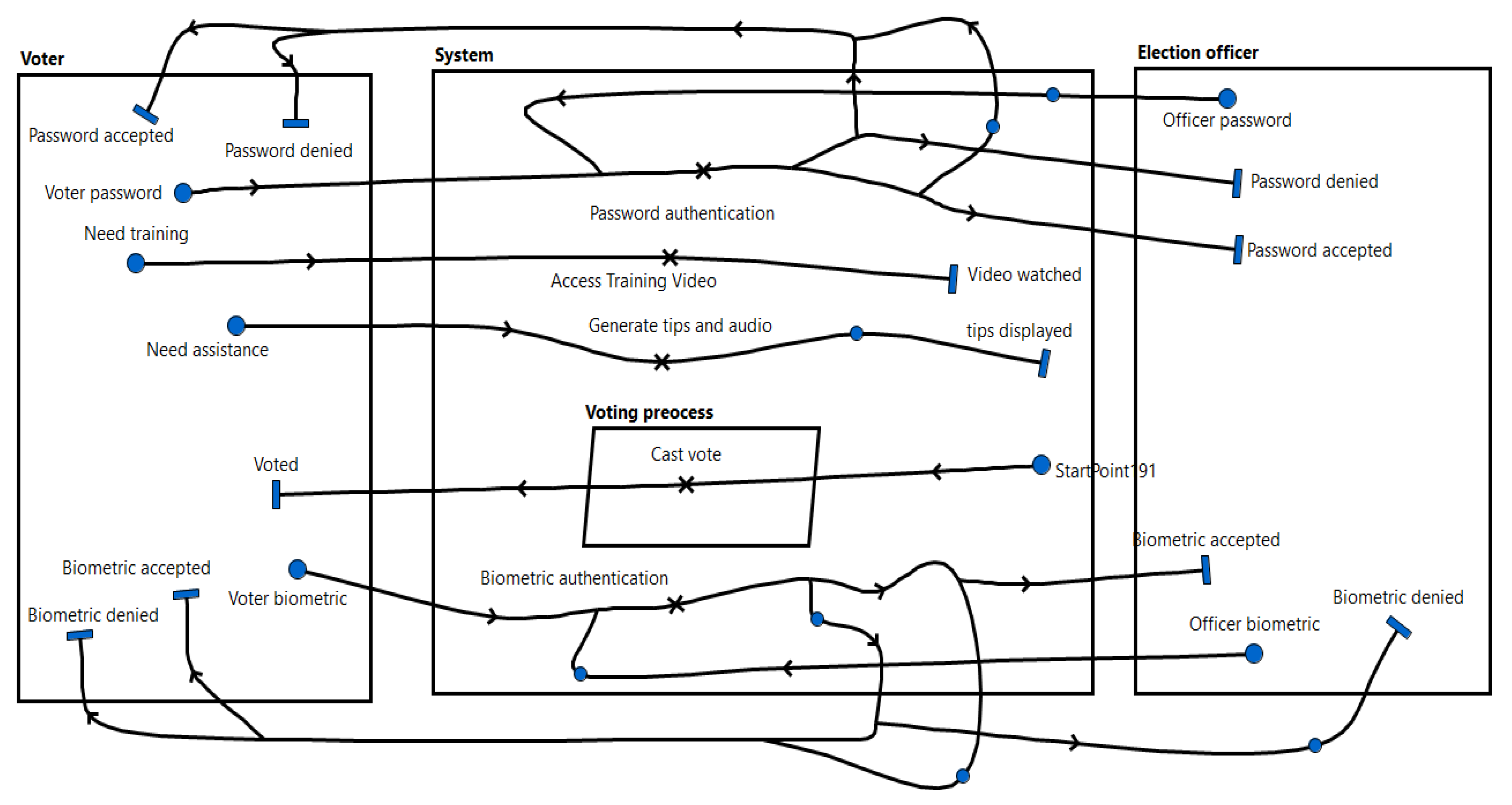
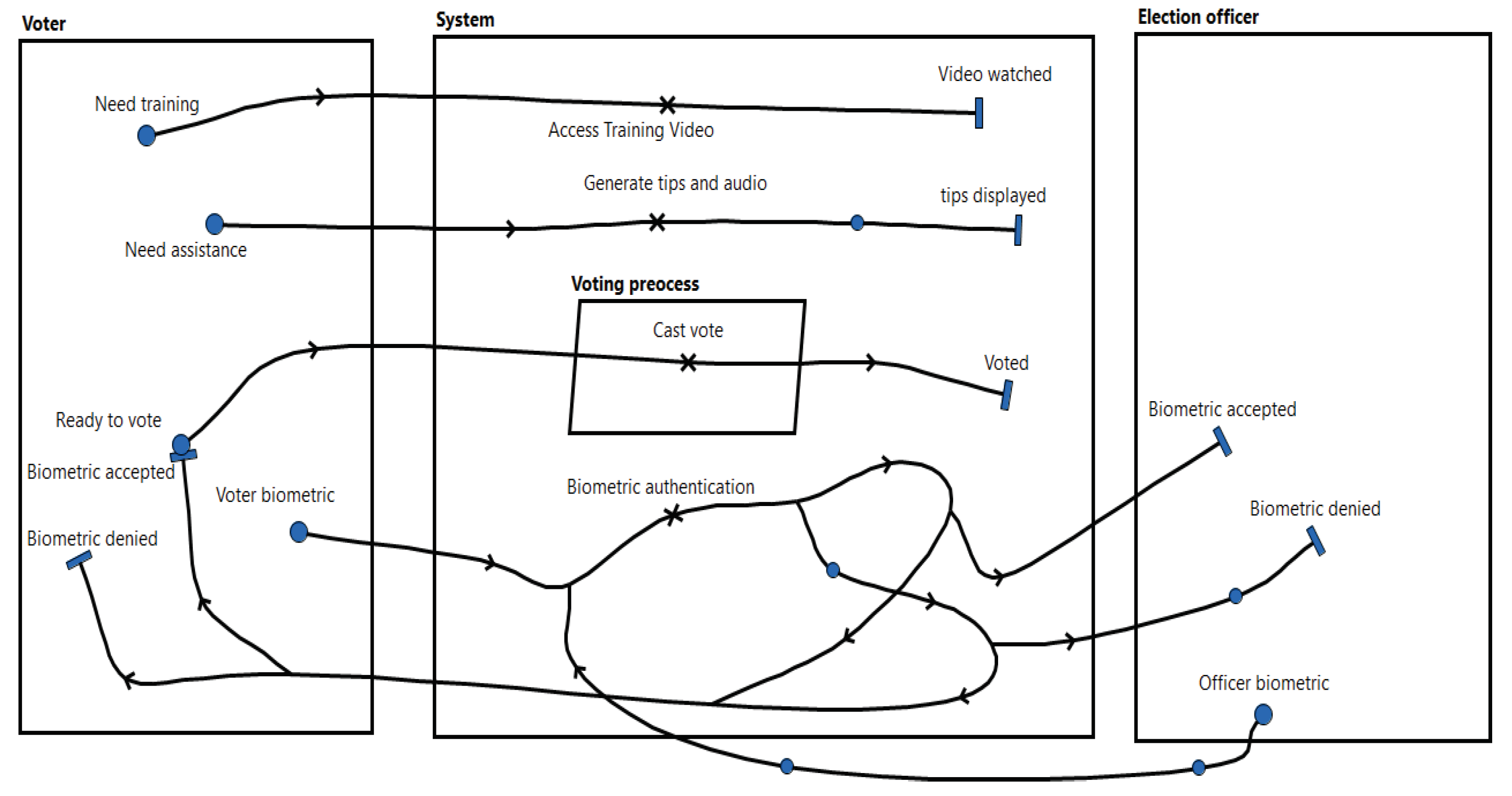
7.4.1. Description of the UCM Model of the Case Study

The inputs to the UCM specification in Figure 10 were generated from the GRL model in Figure 8. Each of the three actors from the input GRL model is transformed into a UCM component. One of the actors, namely, the Security company is not specified in UCM due to the fact that the Hardware security goal whose achievement requires the services of the Security company was rejected in favor of the Software security goal. The three actors specified in UCM are: Voter, Vote officer, and the subsystem voting system. On the other hand, the tasks operationalizing the selected goals are specified; these are: Biometric authentication, Cast vote, Provide training videos, and Tips with audio:
  • “Biometric authentication” aims to achieve the software security goal. The scenario specifying this operation is visually the most complicated despite our objective to keep scenarios’ paths as simple as possible to facilitate the comparison of the suggested UCM process with the existing one. This is especially due to the decision to have two starting points: one from the voter component and the other from the Vote officer’s component. Binding the starting point to a specific component facilitates the visual interpretation of the model but is not a necessity. The main function, specified with the responsibility point labeled Biometric authentication, is to authenticate a user using the input biometric data. This results in a system accepting or denying access to the system.
  • “Cast a vote” is actually a process that can only be started after the voter has successfully been authenticated. A UCM process element is used to specify the process nature of the task and a responsibility point to specify the abstract operation to cast a vote.
  • The “Tips with audio” function is accessible by the user any time when the system is running. The user activates the function represented by the responsibility point to generate tips and audio that enable the system to provide the user with the appropriate onscreen tips or an audio message. This functionality, as are the others, is represented at a high level of abstraction. For example, it does not indicate when only tips or audio is activated and how they are generated.
  • “Training videos” can be accessed at any time by the user during operation. The user who wishes to watch the video has to activate the function to access training videos represented by a UCM responsibility point. This is, in fact, an abstract representation which has to be refined to unpack the complexity of the functionality.

7.4.2. Analysis of the UCM Model of the Case Study

This section briefly touches on three points: the comparison of the UCMs in Figure 5 and Figure 10, the traceability of GRL and UCM models, and the possible contribution of input softgoals in the refinement of the UCM model.
As depicted in Table 1, most of the selected functionalities or generic tasks are specified in both UCM models, except for the password authentication. As discussed earlier, the presence of this functionality in the model in Figure 5 is due to the current construction of UCM and GRL models allowed by the concurrent process. We argued earlier that this is one source of inconsistency in URN models. On the other side, the absence of the same task in the UCM in Figure 10 illustrates our suggestion to delay UCM modeling until the final evaluated GRL model is obtained. In fact, from the GRL model in Figure 8, it is clear that the biometric and password authentications are two alternative solutions for which the biometric authentication is prioritized. Therefore, the password authentication should not be implemented. With complex systems with hundreds of functionalities, if proper care is not taken while developing the UCM and GRL models in parallel, the number of such irrelevant functionalities introduced into the system can also be very high.

Tracing UCM Elements from the Input GRL

Being able to trace the elements of the an input GRL model from the generated UCM is important to ensure the consistency of the URN models. It can be observed from the UCM in Figure 10 that the initial UCM, which is not yet refined, is closely related to the input GRL model from which it was generated. In most cases, the names of GRL elements such as the generic tasks and resources are still very similar in the UCM, making it relatively easy to map the elements of the two models. We therefore suggest to create a mapping (or a traceability) table as soon as the initial UCM is developed to link the elements of the two models, and to update the table progressively when the UCM model is being refined. If properly documented, the table can help, for instance, to guide the formulation of OCL constraints as suggested by Akhigbe et al. [16] to ensure the consistency of both models. It can equally be a good source of inspiration or a guide when refining the UCM model.

Refining the Initial UCM

In general, the initial UCMs need to be refined to reach the desired level of detail. Even when the input scenarios are sufficiently detailed, the UCMs model produced would very likely still need to be refined to include the properties or functionalities related to the system as a whole such as, for instance, inter-process communication, network communication, connecting sub-systems or plugins to the main system, etc. UCM elements such as AndFork, AndJoin, OrFork, OrJoin, Timer, WaitingPlace, Failure points, Stubs and Plug-ins are provided to serve this purpose.
Considering the UCM model of the case study in Figure 10, each functionality/generic task specified needs to be further analyzed and refined. It is relatively easy to observe that the transformation from GRL to UCM did not bring any major change to the initial GRL element. In most cases, for a given GRL task describing a (generic) functionality, the transformation consisted to think about the triggering event and the possible postcondition(s) for the task. The triplet—triggering event/starting condition, the GRL task, and the postcondition(s)—is therefore used to create a scenario path in UCM where:
  • A UCM start point specifies the triggering event or precondition.
  • A UCM responsibility point specifies the GRL task.
  • A UCM endpoint specifies each possible post-condition.
Although there are no prescribed transformation rules to guide the UCM modeling of an input GRL graph, having an initial UCM map that is closely related to the input GRL can considerably facilitate the traceability between the two models. Sketching a traceability table linking back the elements of the initial UCM to those of the GRL graph could very well facilitate the UCM refinement process and contribute to keep the different intermediary models of the system being developed consistent. During the refinement, the source and the why of UCM element(s) being refined would be easily accessible. This also justifies the need to have softgoals (GRL elements describing non-functional requirements) as inputs to UCM.
Traditionally, the refinement of a UCM functionality is (implicitly) based on its business scenario and/or the developer’s understanding of the functionality. These two aspects may not be enough to avoid, for instance, inconsistencies and errors in the refined model if proper care is not taken during the refinement process. Furthermore, in addition to the decomposition of individual functions, the system as a whole may also need to be refined, for example, to decompose the entire system into sub-systems, specify network communication, secure some critical parts of the system, etc. In this regard, we strongly believe that the knowledge and continuous analysis of the input softgoals/non-functional requirements, even though they are not explicitly represented in UCM, would provide guidance during the process and help to improve the quality of the final model.
To conclude the section, let us consider the functionality to access the training videos. When decomposing this function, a number of possibilities is considerable, among which only the most appropriate ones should be retained:
  • Keep a database of videos. For instance to ensure that all users access the same version of the videos.
  • Install a video player.
  • Run a video player to play a downloaded video.
  • Download a video and keep a copy in local host.
  • Play a video directly online.
  • Ensure a stable network connection.
  • Others as needed.
Some of these activities can be combined to ensure access to the training videos. However, knowing that the functionality itself exist to facilitate user experience and considering this goal when refining the functionality, would consequently limit the choice of activities and the way to combine them to construct the business or system scenario. For example, playing a video directly online seems to be an appropriate solution as it would require the user to select a video (from those available in the shared database) and start playing. The associated activities, including the network connection, would therefore be encapsulated in a black box hiding their complexity to the user.

8. Future Work

It is now a duty to develop a tool to support the proposed URN process. To this end, it seems appropriate to first investigate the best possible way to do so. For instance, to literally modify the existing tool, it is necessary to develop a new plugin and attach to the existing jUCMNav tool or to develop a new tool from scratch independently from the existing one. We are also considering the development of a framework or guidelines to facilitate the analysis of softgoals in UCM modeling to improve the quality of the final UCM maps and, hence, that of the URN.
Conducting an empirical study, to confirm the contribution of the proposed URN process to improve the usability of URN as well as the quality of the resulting models, would equally be a good motive for further efforts. A plausible means would be to develop appropriate instruments to collect some statistical data on the use of this model from different sources in order to obtain feedback about the models’ usability.

9. Conclusions

This work has analyzed the existing URN models’ construction process, identified some sources of problems in the final URN models and proposed an improved construction process. All the important ideas raised were illustrated using a reasonably sized case study. The proposed URN models’ construction process consisted to the splitting of the existing process into two independent, ordered and interrelated processes where the GRL model is first constructed, followed by UCMs with inputs to UCM extracted from the GRL model. Due to the (syntactic and semantic) limitations of GRL to serve as input to other systems [36], it appears necessary to think about a mechanism to extract the needed information from a GRL model to serve as inputs to other methods. We have also endeavored to demonstrate the benefit of having softgoals describing non-functional requirements as input to UCM and provided some means to effectively use softgoals in UCM modeling. The use of non-functional requirements in a UCM specification is, in fact, an attempt to address in URN the well-known challenging and well-supported long-lasting problem of finding means to develop NFRs alongside the FRs [40,41].

Author Contributions

Conceptualization, C.D. and J.A.V.d.P.; methodology, C.D.; software, C.D.; validation, J.A.V.d.P. and C.D.; formal analysis, J.A.V.d.P.; investigation, C.D. and J.A.V.d.P.; resources, C.D.; writing—original draft preparation, C.D.; writing—review and editing, C.D. and J.A.V.d.P.; supervision, J.A.V.d.P.; project administration, C.D.; funding acquisition, J.A.V.d.P. All authors have read and agreed to the published version of the manuscript.

Funding

The APC of this article is funded by page fees from the University of South Africa (Unisa) and the Unisa research professor fund of the joint author.

Data Availability Statement

Not applicable.

Conflicts of Interest

The authors declare no conflict of interest.

References

  1. Cervantes-Ojeda, J.; Gómez-Fuentes, M.; Chacón-Acosta, G. Can non-developers learn a simplified modeling notation quickly? J. Softw. Evol. Process. 2022, 34, e2481. [Google Scholar] [CrossRef]
  2. Grobelna, I. Scratch-Based User-Friendly Requirements Definition for Formal Verification of Control Systems. Inform. Educ. 2020, 19, 223–238. [Google Scholar] [CrossRef]
  3. Canché, M.; Ochoa, S.F.; Perovich, D.; Gutierrez, F.J. Analysis of notations for modeling user interaction scenarios in ubiquitous collaborative systems. J. Ambient. Intell. Humaniz. Comput. 2022, 13, 5321–5333. [Google Scholar] [CrossRef]
  4. van der Poll, J.A.; Kotzé, P.; Ahmed, S.; Thiruvengadam, P.; Asmaa, A. Combining UCMs and Formal Methods for Representing and Checking the Validity of Scenarios as User Requirements. In Proceedings of the SAICSIT’03: Proceedings of the 2003 Annual Research Conference of the South African Institute of Computer Scientists and Information Technologists on Enablement through Technology, Johannesburg, South Africa, 17–19 September 2003; pp. 111–113. [Google Scholar]
  5. Qaisar, A.M.; Dragos, T.; Johan, L. Using UML Models and Formal Verification in Model-Based Testing. In Proceedings of the 2010 17th IEEE International Conference and Workshops on the Engineering of Computer-Based Systems, Oxford, UK, 22–26 March 2010; pp. 50–56. [Google Scholar] [CrossRef]
  6. Rasoolzadegan, A.; Barforoush, A. Reliable yet flexible software through formal model transformation (rule definition). Knowl. Inf. Syst. 2014, 40, 79–126. [Google Scholar] [CrossRef]
  7. Jean-Raymond, A. Formal Methods in Industry: Achievements, Problems, Future. In Proceedings of the 28th International Conference on Software Engineering, Shanghai, China, 20–28 May 2006; pp. 761–768. [Google Scholar] [CrossRef]
  8. Alagar, V.S.; Periyasamy, K. Specification of Software Systems; Springer Science & Business Media: Berlin/Heidelberg, Germany, 2011. [Google Scholar]
  9. Gherabi, N.; Bahaj, M. Robust representation for conversion UML class into XML Document using DOM. arXiv 2012, arXiv:1205.5921. [Google Scholar]
  10. Brink, L.; Stoter, J.; Zlatanova, S. UML-Based Approach to Developing a CityGML Application Domain Extension. Trans. Gis 2013, 17, 920–942. [Google Scholar] [CrossRef]
  11. Amyot, D.; He, X.; He, Y.; Cho, D.Y. Generating Scenarios from Use Case Map Specifications. In Proceedings of the QSIC ’03: Proceedings of the Third International Conference on Quality Software, Dallas, TX, USA, 6–7 November 2003; p. 108. [Google Scholar]
  12. Abdelzad, V.; Amyot, D.; Alwidian, S.A.; Lethbridge, T.C. A Textual Syntax with Tool Support for the Goal-oriented Requirement Language. In Proceedings of the Eighth International i* Workshop (ISTAR 2015), Ottawa, ON, Canada, 24–25 August 2015; pp. 61–66. [Google Scholar]
  13. Kehrer, T.; Ihler, E. Process-integrated refinement patterns in UML. In Proceedings of the 21st International Conference on Software and Systems Engineering and their Applications (ICSSEA), Paris, France, 9–11 December 2008. [Google Scholar]
  14. Said, M.Y.; Butler, M.; Snook, C. Class and state machine refinement in UML-B. In Proceedings of the Workshop on Integration of Model-Based Formal Methods and Tools (Associated with IFM 2009), Eindhoven, The Netherlands, 2–3 November 2009. [Google Scholar]
  15. Liu, Z.; Li, X.; Liu, J.; Jifeng, H. Consistency and refinement of UML models. In Consistency Problems in UML-Based Software Development: Understanding and Usage of Dependency; Springer: Berlin/Heidelberg, Germany, 2004; p. 19. [Google Scholar]
  16. Akhigbe, O.; Amyot, D.; Anda, A.A.; Lessard, L.; Xiao, D. Consistency Analysis for User Requirements Notation Models. In Proceedings of the iStar, Beijing, China, 12–13 September 2016; pp. 43–48. [Google Scholar]
  17. Sebastián, G.; Gallud, J.A.; Tesoriero, R. Code generation using model driven architecture: A systematic mapping study. J. Comput. Lang. 2020, 56, 100935. [Google Scholar] [CrossRef]
  18. Ozkaya, M.; Erata, F. Understanding Practitioners’ Challenges on Software Modeling: A Survey. J. Comput. Lang. 2020, 58, 100963. [Google Scholar] [CrossRef]
  19. ITU-T, Recommendation Z.151 (10/12), User Requirements Notation (URN)—Language Definition, Geneva, Switzerland. 2012. Available online: https://www.itu.int/rec/T-REC-Z.151/en (accessed on 6 June 2023).
  20. Amyot, D.; Mussbacher, G. URN: Toward a New Standard for the Visual Description of Requirements. In Telecommunications and Beyond: The BroaderApplicability of SDL and MSC; Sherratt, E., Ed.; Springer: Berlin/Heidelberg, Germany, 2003; pp. 21–37. [Google Scholar]
  21. Amyot, D.; Mussbacher, G. User Requirements Notation: The First Ten Years, The Next Ten Years (Invited Paper). J. Softw. 2011, 6, 747–768. [Google Scholar] [CrossRef] [Green Version]
  22. Buhr, R.J.A.; Casselman, R.S. Use Case Maps for Object-Oriented Systems; Prentice Hall: Hoboken, NJ, USA, 1999. [Google Scholar]
  23. Liu, L.; Yu, E. From Requirements to Architectural Design—Using Goals and Scenarios. In Proceedings of the ICSE 2001, Toronto, ON, Canada, 12–19 May 2001. [Google Scholar]
  24. Roy, J.F.; Kealey, J.; Amyot, D. Towards Integrated Tool Support for the User Requirements Notation. In System Analysis and Modeling: Language Profiles; Gotzhein, R., Reed, R., Eds.; Lecture Notes in Computer Science; Springer: Berlin/Heidelberg, Germany, 2006; Volume 4320, pp. 198–215. [Google Scholar]
  25. Buhr, R.J.A. Use Case Maps: A New Model to Bridge the Gap Between Requirements and Design. In Proceedings of the SCE 95—Conttribution to the OOPSLA 95 Use Case Map Workshop, Austin, TX, USA, 15 October 1995; pp. 1–4. [Google Scholar]
  26. Amyot, D.; Buhr, R.J.A.; Gray, T.; Logrippo, L. Use Case Maps for the Capture and validation of Distributed Systems Requirements. In Proceedings of the ISRE’99, Fourth International Symposium on Requirements Engineering, Limerick, Ireland, 7–11 June 1999. [Google Scholar]
  27. Mussbacher, G.; Amyot, D. Goal and Scenario Modeling, Analysis, and Transformation with jUCMNav. In Proceedings of the ICSE Companion, Washington, DC, USA, 16–24 May 2009; pp. 431–432. [Google Scholar]
  28. Mussbacher, G.; Ghanavati, S.; Amyot, D. Modeling and Analysis of URN Goals and Scenarios with jUCMNav. In Proceedings of the 2009 17th IEEE International Requirements Engineering Conference, Washington, DC, USA, 31 August–4 September 2009; pp. 383–384. [Google Scholar] [CrossRef]
  29. Amyot, D.; Rashidi-Tabrizi, R.; Mussbacher, G.; Kealey, J.; Tremblay, E.; Horkoff, J. Improved GRL Modeling and Analysis with jUCMNav 5. In Proceedings of the iStar, Valencia, Spain, 17–18 June 2013; pp. 137–139. [Google Scholar]
  30. Amyot, D.; Ghanavati, S.; Horkoff, J.; Mussbacher, G.; Peyton, L.; Yu, E. Evaluating goal models within the goal-oriented requirement language. Int. J. Intell. Syst. 2010, 25, 841–877. [Google Scholar] [CrossRef]
  31. Baslyman, M.; Amyot, D.; Mylopoulos, J. Reasoning about Confidence in Goal Satisfaction. Algorithms 2022, 15, 343. [Google Scholar] [CrossRef]
  32. Merx, G.G.; Norman, R.J. Unified Software Engineering with Java; Prentice-Hall, Inc.: Hoboken, NJ, USA, 2006. [Google Scholar]
  33. Sommerville, I. Software Engineering, 8th ed.; Addison-Wesley: Boston, MA, USA, 2007. [Google Scholar]
  34. Herrmann, A.; Paech, B. MOQARE: Misuse-oriented quality requirements engineering. Requir. Eng. 2008, 13, 73–86. [Google Scholar] [CrossRef]
  35. Gregor, V.B. User Requirements Notation (URN). Powerpoint Presentation. 2010. Available online: http://csis.pace.edu/~marchese/CS775/Lectures/User%20Requirements%20Notation.pptx (accessed on 15 October 2021).
  36. Mussbacher, G.; Amyot, D.; Heymans, P. Eight Deadly Sins of GRL. In Proceedings of the iStar, Trento, Italy, 28–29 August 2011; pp. 2–7. [Google Scholar]
  37. Dorin Bogdan, P.; Murray, W. Software Performance Models from System Scenarios. Perform. Eval. 2005, 61, 65–89. [Google Scholar] [CrossRef]
  38. Miga, A. Application of Use Case Maps to System Design with Tool Support. Ph.D. Thesis, Carleton University, Ottawa, ON, Canada, 1998. [Google Scholar]
  39. Dongmo, C. Formalising Non-Functional Requirements Embedded in User Requirements Notation (URN) Models. Ph.D. Thesis, The University of South Africa, Pretoria, South Africa, 2016. Available online: https://uir.unisa.ac.za (accessed on 6 June 2023).
  40. Silva, A.; Pinheiro, P.; Albuquerque, A.; Barroso, J. A Process for Creating the Elicitation Guide of Non-functional Requirements. In Software Engineering Perspectives and Application in Intelligent Systems; Silhavy, R., Senkerik, R., Oplatkova, Z.K., Silhavy, P., Prokopova, Z., Eds.; Springer International Publishing: Cham, Switezerland, 2016; pp. 293–302. [Google Scholar]
  41. Cai, K.Y. Non-Functional Computing: Towards a More Scientific Treatment to Non-Functional Requirements. In Proceedings of the 31st Annual International Computer Software and Applications Conference (COMPSAC 2007), Beijing, China, 24–27 July 2007; Volume 2, pp. 493–494. [Google Scholar] [CrossRef]
Figure 1. URN conceptual model [19].
Systems 11 00301 g001
Figure 2. URN construction process [23].
Systems 11 00301 g002
Figure 3. Vertical relationship between GRL and UCM.
Systems 11 00301 g003
Figure 4. The GRL model of the case study.
Systems 11 00301 g004
Figure 5. The UCM model of the case study.
Systems 11 00301 g005
Figure 6. The inspiring relationship between GRL and UCMs, extracted from [35].
Systems 11 00301 g006
Figure 7. The proposed GRL model construction.
Systems 11 00301 g007
Figure 8. The proposed GRL model of the case study.
Systems 11 00301 g008
Figure 9. The proposed UCM model construction.
Systems 11 00301 g009
Figure 10. The new UCM model of the case study.
Systems 11 00301 g010
Table 1. Comparing the two UCMs.
Comparing the Two UCMs Based on Specified Functionalities
Task/Generic OperationUCM in Figure 5
(Current Process)
UCM in Figure 10
(Improved Process)
Biometric authenticationYesYes
Password authenticationYesNo
Casting a voteYesYes
Generate Tips and AudioYesYes
Access training videosYesYes
Disclaimer/Publisher’s Note: The statements, opinions and data contained in all publications are solely those of the individual author(s) and contributor(s) and not of MDPI and/or the editor(s). MDPI and/or the editor(s) disclaim responsibility for any injury to people or property resulting from any ideas, methods, instructions or products referred to in the content.

