1. Introduction
As it is well-known, carbon nanostructures provide extraordinary combined mechanical, electrical, thermal properties, especially when talking about carbon whiskers, which have unique strength and electrical conductivity [
1]. Graphene, a well-known two-dimensional material, gave a fresh concept for new three-dimensional (3D) structures with complex architecture fabricated on the basis of graphene [
2,
3,
4]. Carbon structures with unique electrical, mechanical, and thermal properties are of great interest today [
5,
6,
7,
8,
9,
10,
11]. Recently, considerable attention has been paid to graphene fibers, a new type of carbon fiber consisting of many monolayers of wrinkled and crumpled graphene sheets [
12,
13,
14,
15,
16,
17]. Graphene films/papers/fibers can be fabricated by many sophisticated solution-processing methods. Such carbon fibers exhibit high tensile strength, have low weight, and can be easily functionalized by other elements. There has been considerable interest in carbon nanopolymorphs like graphene or carbon nanotubes which can be great precursors for carbon fibers [
16,
17].
Here, one of the fiber structures like crumpled graphene is considered. This structure mainly consists of defected or wrinkled single-layer graphene flakes with a size of a few nanometers. Between some graphene flakes, new chemical bonds can appear; however, carbon atoms with
hybridization dominate. Carbon atoms with other hybridization states, such as
or
, have small fractions [
18]. However, the size and type of structural units can significantly affect the physical and mechanical properties of 3D nanostructures. In the Ref. [
19], the similar fiber structure consists of highly ordered large-sized graphene, with small-sized graphene filling the cavities between large flakes. To date, most works have been dedicated to the fabrication process and structure characterization of such fibers, and to the study of thermal conductivity and mechanical properties. However, deformation mechanisms and the effects of structure morphology are unclear.
In the experiment, it is much more complicated to study the structural peculiarities and their effect on the deformation behavior than to analyze tensile mechanisms on an atomistic level. Comparatively, molecular dynamics (MD) simulation allows to analyze a wide variety of microstructures, show atomic movement, and understand tensile mechanisms of carbon structures. So far, advances in computer science have allowed for the successful use of MD simulations to investigate the mechanical properties of aerogels [
12,
20,
21,
22,
23,
24].
To date, several factors affecting the mechanical properties of graphene fibers have been analyzed: (i) The type and combination of the structural elements; (ii) intrinsic defects of graphene; and (iii) the orientation of graphene flakes. For example, the addition of carbon nanotubes to graphene fiber increases its strength and elastic modulus [
25,
26]. Intrinsic defects, such as atomic defects of graphene sheets, nanoscale voids, and boundaries decrease the fiber strength [
27]. In the Refs. [
28,
29], it was shown that the right orientation of graphene flakes results in higher fiber strength. Most of these factors are directly connected with the fabrication technique. The mechanical properties of fibers obtained by wet-spinning are generally superior to those achieved using other methods [
28]. However, there is a great difference in the values of the tensile strength and Young’s modulus of different fibers, since it is a reflection of the sheet alignment and type of interaction between them. Thus, the nature and type of fiber precursors are of great importance, as well as the type of building unit and graphene fiber property.
In the present work, simulation samples of crumpled graphene consisting of randomly arranged crumpled graphene flakes are constructed. Molecular dynamics simulation is conducted to study the tensile behavior of these graphene fibers under uniaxial tensile loading.
2. Simulation Details
Crumpled graphene with two different structure morphologies is considered. The initial structure is composed of graphene flakes (GFs) of two types—small GFs of the same size and shape (Structure A), and GFs of different sizes and shapes (Structure B).
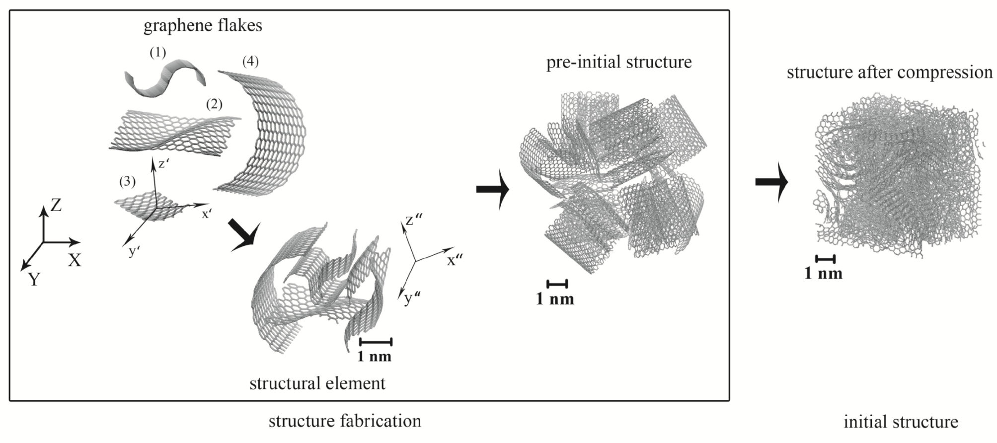
The example of the fabrication of Structure A is presented in
Figure 1. As it can be seen, the structural element for Structure A is a graphene flake consisting of 252 carbon atoms, cut from a carbon nanotube with a diameter of about 1 nm. All the flakes in Structure A are of the same size. Every single flake with the system of axes (
) is rotated randomly in comparison with the main coordinates (
) to obtain a 3D structure with a random orientation of GFs (see
Figure 1). These single flakes are combined into the pre-initial structure by the homemade program which allows to rotate each flake randomly and repeat each GF five times along
X,
Y, and
Z. The structure consists of 125 structural elements (GFs) which are randomly oriented. Then, to obtain the structure with an even more random shape of flakes, this pre-initial sample is exposed at room temperature for 100 ps (structure after annealing in
Figure 1). This process is used to accelerate the formation of new
or
bonds between atoms with dangling bonds on the edges of GFs. It is done to obtain a more uniform 3D structure with GFs of different shapes (see structure after annealing,
Figure 1). It should be noted that carbon atoms at the edges of graphene flakes are not chemically modified and have
hybridization.
For Structure B, the initial element is much more complex and consists of flakes of different sizes and shapes. As it is shown in
Figure 2, four different flakes are taken: the size of the graphene flakes ranges from 80 to 500 atoms with an average of 228 atoms. Different flakes are obtained from planar graphene by the application of strain to form a rippled structure, which is done by the homemade program. The details of this procedure are described in the Ref. [
30], where the authors defined special deformation conditions to obtain rippled graphene with given structural parameters. For example, GF(1) is obtained at
and
, GF(2) is obtained at
,
and
, while GF(3) is obtained at
,
and
. In comparison, GF(4) is cut from a carbon nanotube. These GFs with the system of axes (
) are randomly rotated to obtain the final structural element with the system of axes (
), which were further used to obtain a 3D poly-disperse structure. Note that flakes (2) and (3) are copied two times, but with different orientations. This structural element is repeated
to obtain a single 3D structure B (pre-initial structure in
Figure 2).
It should be noted that the effect of the randomness of the orientation of structural units is such that the crumpled structures were studied by authors previously [
22,
24]. It was shown that there is no considerable effect of the angle of the initial orientation of graphene flakes on the mechanical properties of the final structure. The main point is to obtain an anisotropic structure with randomly oriented flakes, while the rotation angles are not important.
Parameters for both structures are presented in
Table 1. For both structures, the number of atoms is defined as
N, and the size of the compressed sample is
(as shown in
Figure 1). The initial volume
V and density
of crumpled structures is also defined. Another very important characteristic of such crumpled structures is their porosity, since the physical properties of graphene foam/fiber are strongly dependent on the pore size. However, this parameter is not discussed here. In the present model, both structures are compressed until the highest possible density is achieved. Thus, there are almost no pores in the structures under consideration. Here, the density of the graphene fiber can characterize the porosity: density is close to the diamond density (3.6 g/cm
3), but lower, since there is no full
hybridization and graphene flakes are densely packed but mostly connected by van der Waals bonds.
Periodic boundary conditions were applied along the
X-,
Y-, and
Z-axes. All the simulations were conducted using the LAMMPS package with the AIREBO [
31] interatomic potential for the description of the interaction between carbon atoms, which include both covalent bonds in the basal plane of the graphene flake and van der Waals interactions between GF [
22,
23,
24,
32,
33,
34]. A time-step of 0.2 fs is used. The Nose–Hoover thermostat was used to control the system temperature around 300 K. The Lennard–Jones potential was used to describe the van der Waals interactions between neighboring structural units with the parameter
r = 3.4 Å, at which distance each carbon pair has the minimal potential energy of −0.024 eV.
To obtain a crumpled graphene structure, hydrostatic compression was applied (
) at 300 K to the structure composed of different flakes. The value of
increases at a given strain rate
= 0.01 ps
. In
Figure 1 and
Figure 2, initial samples A and B are shown as structures after compression. As it was previously shown for similar models, the size of the computational cell does not considerably affect the stress–strain curves under compression [
22]. Thus, the small difference in the size of the final crumpled structures can be neglected.
To study mechanical properties of the considered samples, uniaxial tension of the constructed graphene fibers was conducted along the X-, Y-, and Z-axes at a constant strain rate of = 0.005 ps under an NVT ensemble. Stress components for the whole sample are calculated during the simulation.
3. Results and Discussion
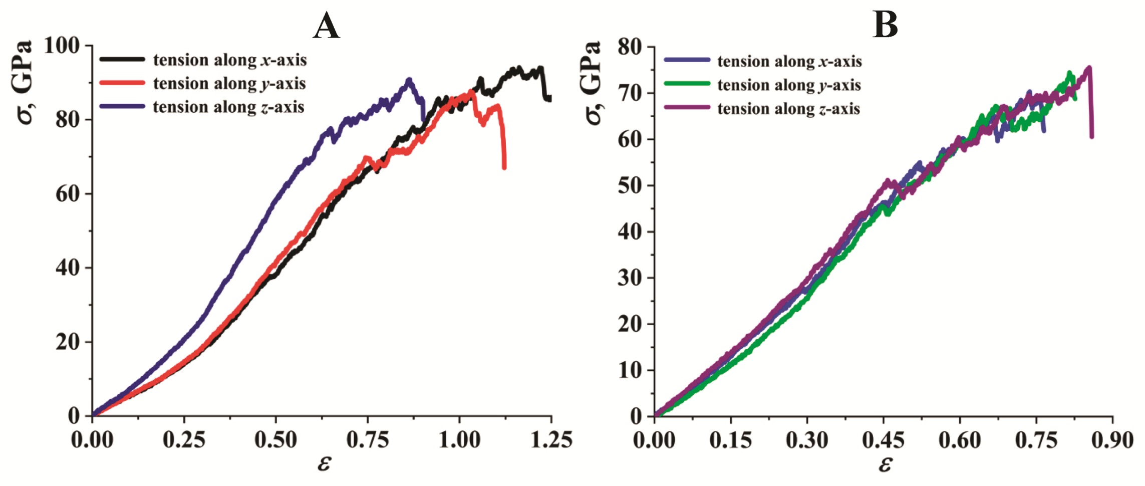
In
Figure 3, the uniaxial tensile stress–strain curves for graphene fibers with two morphologies (A and B) are presented. Tension along
x-,
y-, and
z-axes is presented to analyze whether these structures are isotropic or not. It is shown that both simulated fibers undergo a linear elastic deformation until strain of about
= 0.15. After the elastic deformation, structures start to deform non-elastically as the applied strain increases. After the stress reaches a peak, it suddenly drops to a lower level and then exhibits a flow tendency. These drops on the curve indicate that graphene fibers can undergo plastic deformation. Each drop corresponds to the appearance of the new microcracks in the structure, but these cracks do not propagate further. Structural transformations during tension will be analyzed further.
By fitting the slope of the linear elastic range of the stress–strain curves, Young’s moduli of the crumpled graphene fibers were found. For Structure A (monodisperse), Young’s modulus for two directions of axial tension is close and equal to 50.5 GPa for tension along the x-axis, and 53.2 GPa for tension along the y-axis. However, for tension along the z-axis, Young’s modulus is much bigger and equal to 70.9 GPa. For Structure B (polydisperse), the slope of the curves is close, but also results in a difference between Young’s modulus: 87.2 GPa (tension along the x-axis), 77.3 GPa (tension along the y-axis), and 92.1 GPa (tension along the z-axis) with an average value of 85.5 GPa. It can be seen that the polydisperse structure can be considered as isotropic rather than monodisperse. It can also be concluded that a polydisperse structure is stronger in the elastic regime and can sustain about two times higher deformation.
The peak stress in the stress–strain curve is the tensile strength of the crumpled graphene. The obtained critical values are presented in
Table 2 together with Young’s modulus. In contrast with the elastic regime, during inelastic deformation, monodisperse structure A sustains higher tensile stresses (for about 10 to 20 GPa). Again, Structure B is isotropic with a slight difference between the course of the stress–strain curves. Despite the quite large difference in the course of the stress–strain curves for Structure A, the tensile strength is the same for all tension directions. Here, tension direction mostly affects the elastic properties.
The obtained values of Young’s modulus can be compared to what is known from the literature. However, there is a spread in the reported values, since structure morphology can play a very important role, as well as the syntheses method. For example, in the Ref. [
35], quite low carbon structures for Young’s modulus and tensile strengths were found (5.4–7.7 GPa and 100–140 MPa, respectively). In this experimental work, graphene fiber consists of crumpled graphene flakes, and had lamellar and helical structural elements after fabrication. They showed that more compact stacking (small interlayer distance between graphene flakes) results in the increase of Young’s modulus. However, the strength of this special experimentally obtained fiber can be increased by optimization of the fabrication process. This work allows for an understanding of the great importance of the fabrication process. In the Ref. [
28], much stronger graphene fibers, which are compact origami-flower-like structures with bends, were shown with a modulus of 11.2 GPa, a tensile strength of 500 MPa. In the Ref. [
19], graphene fiber with a unique microstructure was obtained with a modulus of 135 GPa and tensile strength of about 1.08 GPa. Here, the authors showed that a special microstructure composed of large- and small-sized graphene sheets results in different great properties, like high thermal conductivity and strength, in comparison with the microstructure composed of just large-sized graphene in the Ref. [
12] by MD simulations of graphene fiber, Young’s modulus in a range 74–285 GPa, and tensile strength in the range of 2.1–14.0 GPa. In this work, the graphene fibers were composed of many rippled graphene sheets with topological defects arranged along the axial direction of the fiber. As it is shown if the structure continuity (which can also be considered as the isotropy of such fiber) decreases, both the modulus and strength of the simulated fiber decrease significantly. All the considered fibers have unique micro-structures by the size of the structural elements and their placement in the fiber. The simulated fibers are definitely more ideal and have fewer defects than the experimental samples, which considerably affect the values of Young’s modulus. It should be noted that such a high value of tensile strength can also be related to the quite high strain rate used in the MD simulations, which is several orders of magnitude higher than that used in experiments. This comparison confirms that structure peculiarities play an important role in the mechanical behavior of graphene fibers.
In
Figure 4, the stress–strain curves during tension are presented for uniaxial tension along
x for both structures for comparison. This direction of tension was chosen as representative, since all the obtained stress–strain curves are very similar. However, Structure A was additionally analysed to understand whether there was a difference in the microstructure of the sample. It was found, that despite the difference in the course of the curve for tension along
z-axis in comparison with tension along
x-axis, there were no peculiarities in the structure.
The snapshots of the structure surface at critical points during tension along the x-axis are presented. Since periodic boundary conditions are applied, there was no difference in whether the cross-section or surface was considered. However, several cross-sections of the sample were analysed during simulation to confirm this statement. No significant differences in the microstructure were defined. A slightly different pore distribution was found depending on different cross-sections. On average, due to the homogeneity of the structure, the snapshot of the surface was representative. As it can be seen, there is a considerable difference between the deformation behavior of these two structures. Monodisperse structure A has an almost two times bigger critical strain and tensile strength. In the monodisperse structure, all the flakes were combined into a much more homogeneous structure during initial compression, and the equality of flakes (by size) allowed to obtain much more -bonds on the edges of graphene flakes. The appearance of such -bonds resulted in an increase of tensile strength and a decrease in the critical deformation for Structure B.
At point I’, the first drop on the stress–strain curve is observed, which is connected with the appearance of the first nano-pore for Structure B. However, if for Structure B, pores can be clearly seen from the snapshot, even without additional analysis, for Structure A, pores large enough to be seen can be found just close to the critical fracture point. In fact, for Structure A, the first pores appear just at point II. Structure A has much more elongation due to the better and more uniform morphology.
4. Conclusions
The mechanical response of two crumpled graphene samples of different morphologies to the tensile stress was studied by molecular dynamics simulation. The effect of tension direction and structural morphology on the mechanical properties was analyzed.
It was shown that crumpled graphene structure is also isotropic and can be deformed during different directions without considerable changes in the stress–strain response. However, Young’s moduli of poly- and mono-disperse fibers can be different in an elastic regime.
It was found that during inelastic deformation, mono-disperse crumpled graphene has higher tensile strength and can be stretched to higher elongations. Quite high tensile strength was obtained for both structures; however, it can be connected with the high strain rate applied in MD simulations. Nevertheless, qualitatively, the present work successfully characterized the mechanical response of fibers with different morphologies.
The understanding of changes in properties defined by the special structural morphology is of high importance for the property control of different materials. As mentioned previously [
35], the compactness of the stacking (small interlayer distance between graphene flakes), which is defined by the fabrication process, results in the increase of the mechanical properties. In the present work, the importance of the structure morphology is also shown. The other important impact of the work is that it gives the understanding of the effect of strain on the properties, since specific deformation can affect the electronic properties of the various structures [
36].


