Article

Tribological Performance of PVD Film Systems Against Plastic Counterparts for Adhesion-Reducing Application in Injection Molds

by
Wolfgang Tillmann
,
Nelson Filipe Lopes Dias
*,
Dominic Stangier
and
Nikolai Gelinski
Institute of Materials Engineering, TU Dortmund University, Leonhard-Euler-Str. 2, D-44227 Dortmund, Germany
*
Author to whom correspondence should be addressed.
Coatings 2019, 9(9), 588; https://doi.org/10.3390/coatings9090588
Submission received: 2 September 2019 / Revised: 13 September 2019 / Accepted: 16 September 2019 / Published: 17 September 2019
(This article belongs to the Special Issue Magnetron Sputtering Deposited Thin Films and Its Applications)

Abstract

:
The deposition of physical vapor deposition (PVD) hard films is a promising approach to enhance the tribological properties of injection molds in plastic processing. However, the adhesion is influenced by the pairing of PVD film and processed plastic. For this reason, the friction behavior of different PVD films against polyamide, polypropylene, and polystyrene was investigated in tribometer tests by correlating the relation between the roughness and the adhesion. It was shown that the dispersive and polar surface energy have an impact on the work of adhesion. In particular, Cr-based nitrides with a low polar component exhibit the lowest values ranging from 65.5 to 69.4 mN/m when paired with the polar polyamide. An increased roughness leads to a lower friction due to a reduction of the adhesive friction component, whereas a higher work of adhesion results in higher friction for polyamide and polypropylene. Within this context, most Cr-based nitrides exhibited coefficients of friction below 0.4. In contrast, polystyrene leads to a friction-reducing material transfer. Therefore, a customized deposition of the injection molds with an appropriated PVD film system should be carried out according to the processed plastic.

1. Introduction

Injection molding is a cyclic process for the cost-effective mass production of plastic components with complex geometries at relatively low processing temperatures [1]. The cycle sequence consists of mold closing, injection of melt, packing to compensate the shrinkage, cooling, and mold opening when ejecting the parts [2]. Depending on the processed plastic, the injection molding tools are exposed to high tribological loads and subjected to corrosion and pitting [3]. Moreover, the molded parts tend to stick on the surface of the tool, resulting in a buildup and restricting the productivity of the process as well as the quality of the plastic parts [4]. Within this context, lower adhesion strengths between injection mold and molded part also enable to reduce the ejection forces, which allows reduction of the dimensions of the ejection system within the mold, thus exploiting the attained space by expanding the cooling circuit [5]. As a consequence, the cooling time is reduced and higher production rates can be achieved [6]. Therefore, a suitable surface modification of the injection molding tools is necessary to optimize the tribological properties [7].
A promising approach is the deposition of PVD (physical vapor deposition) films with low adhesion properties to plastic parts [8], a high wear resistance [9,10], and a high corrosion resistance [11]. Within this context, several research works deposited different PVD film systems and investigated either the surface free energy and adhesion behavior in abstracted laboratory tests [12,13] or determined the ejection forces in application-oriented tests [14,15]. Bagcivan et al. conducted high-temperature contact angle measurements on chromium aluminum oxynitride (CrAlON) films and uncoated American Iron and Steel Institute (AISI) 420 with polymethyl methacrylate and reported larger contact angles for the oxynitride coatings [12]. In addition, lower coefficients of friction for CrAlON were observed when compared to AISI 420 and it was concluded that the adhesion behavior has an impact on the friction [12]. Bobzin et al. also investigated the wetting behavior of uncoated AISI 420 and chromium aluminum nitride (CrAlN) as well as CrAlON films with polycarbonate (PC) at 280 °C and observed the largest contact angles for the oxynitridic films [13]. Furthermore, an adhesion test in compliance with DIN EN ISO 4624 was performed to determine the adhesion tensile strength of solidified PC on the surface systems [14]. Lower adhesion tensile strengths for the films were reported in comparison to uncoated steel, but no significant difference between CrAlON and CrAlN was detected. Sasaki et al. deposited titanium nitride (TiN), chromium nitride (CrN), diamond-like carbon (DLC) as well as tungsten carbon carbide (WC/C) and determined the ejection force when removing molded polypropylene (PP) and polyethylene terephthalate (PET) parts from the core [15]. Lower ejection forces for the PVD films were noted in comparison to the uncoated mold, but an explanation for this behavior was not given. Burkard et al. investigated the correlation between film system and plastic counterpart on the ejection force by testing CrN, WC/C, TiN, titanium aluminum nitride (TiAlN) with polyamide (PA), PC, acrylonitrile butadiene styrene as well as polyoxymethylene and observed a different behavior for each plastic counterpart [16]. Burkard et al. concluded that it is not possible to make a general statement, concerning which film system is suitable to reduce the ejection force as this depends on its pairing with the plastic part.
For this reason, the pairing of the PVD film system and the processed plastic part has a key role in the tribological performance of the PVD hard films. However, it should be noted that besides the chemical composition of the PVD films, the roughness profile also has an influence on the friction component and should therefore be taken into consideration as well [17]. Thus, a total amount of eight PVD film systems with different chemical composition and mechanical properties were analyzed regarding their tribological behavior against PA, PP, and polystyrene (PS). The surface energy of the PVD films was determined in laboratory tests and the work of adhesion with PA, PP, and PS was calculated theoretically. The friction against the plastic counterparts was analyzed in tribometer tests. Based on the results, a correlation between the roughness and the adhesion properties was identified, which has an effect on the resulting friction behavior. A comprehensive understanding of this relation allows choosing a suitable PVD film to reduce the adhesive friction component in injection molding.

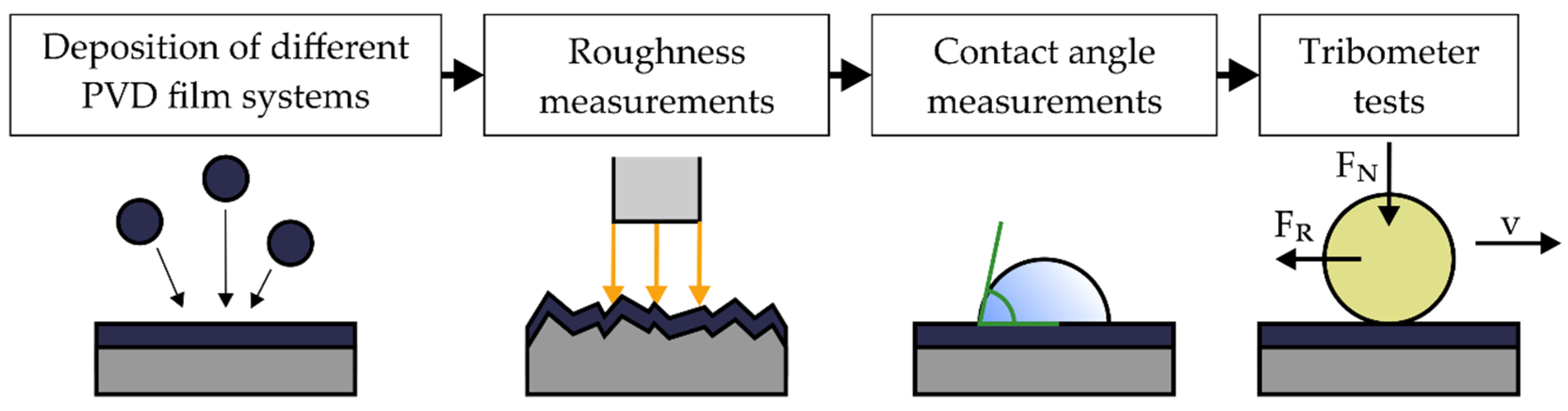
2. Materials and Methods

Quenched and tempered AISI H11 steel with a hardness of 7.0 ± 0.3 GPa was used as substrate material and polished prior to the depositions. The metallographical preparation consisted of grinding with SiC papers from 320 to 1200 grits for 3 min each and polishing using diamond suspension from 9 to 1 µm gran size for 6 min each. The steel is characterized by a high toughness, high-temperature strength, and high thermal shock resistance and is utilized as a tool steel for injection molds in plastics processing [18]. The deposition of the PVD films was carried out by means of an industrial magnetron sputtering device CC800/9 Custom (CemeCon AG, Würselen, Germany). A total of eight different film systems from the groups of Cr-based nitrides, oxides, and DLC films were selected for the experiments (see Figure 1). Since the adhesion behavior depends on the pairing between the PVD film and the molded plastic part, an appropriated PVD film system for adhesion-reducing application in injection molding of PA, PP, and PS needs to be determined first. For this purpose, PVD films of industrial relevance were selected to cover a broad range of systems with different chemical composition in order to obtain distinct surface energies and consequently a different adhesion behavior with PA, PP, and PS. Moreover, these films were deposited either in direct current magnetron sputtering (dcMS), mid-frequency magnetron sputtering (mfMS), or high-power impulse magnetron sputtering (HiPIMS) mode. Within this context, CrN and CrAlN films were synthesized by dcMS as well as HiPIMS. This allows synthesis of film systems with a similar chemical composition, but with different topographical structures caused by the sputtering technique. This allows consideration of the influence of the surface structure on the tribological behavior of the films against the counterpart. Furthermore, chromium aluminum silicon nitride (CrAlSiN) was deposited in dcMS mode. From the group of the oxidic films, amorphous aluminum oxide (Al2O3) was reactively sputtered from aluminum targets in the mfMS mode. All film systems were applied as a monolayer on the steel substrate. Besides the monolayer systems, hydrogen-free amorphous carbon (a-C) and hydrogenated amorphous carbon (a-C:H) films were deposited by mfMS. In order to improve the adhesion of the carbon layers to the substrate, a graded chemical transition with CrN, chromium carbonitride (CrCN), and chromium carbide (CrC) interlayers were sputtered prior to the a-C and a-C:H top layer. The graded systems as well as the deposition process are described in more detail by Hoffmann [19].
The deposition parameters of the PVD films are summarized in Table 1. All the targets had a size of 500 mm × 88 mm. It is worthwhile to mention that the AlCr20 and AlCr24 targets consisted of aluminum (purity 99.5%) and 20 or 24 chromium plugs (purity 99.9%). An overview of the chemical composition and the mechanical properties of the eight PVD films used in this study is given in Table 2. In addition, the uncoated AISI H11 steel was used as reference for comparison with the PVD films.
The morphology and topography of the PVD films were investigated in SEM analysis using a FE-JSEM 7001 (Jeol, Akishima, Japan). In addition, the roughness profile of the PVD films and the uncoated AISI H11 was analyzed with the confocal 3D microscope μsurf (NanoFocus, Oberhausen, Germany). The arithmetical mean roughness, Ra, and the mean roughness depth, Rz, were determined according to DIN EN ISO 4287 and 4288 [20,21]. The contact angle measuring system G40 (Krüss, Hamburg, Germany) was employed, in order to characterize the surface free energy. Distilled water, ethylene glycol, dimethylformamide, 1-octanol as well as 1-decanol were used as test liquids. The disperse and polar components of their surface tension are given in Table 3. The static contact angles of five measuring points were determined for each surface system when wetted with the respective test liquids. The static contact angles were measured using an optical measuring system, which determined the drop profile and consequently calculated the angles. A total of 10 measurements per testing liquid and PVD film were carried out. The arithmetic mean value of the measured contact angle θ was used to calculate the disperse component, σ s D , and the polar component, σ s P , of the surface free energy, σ s , according to the method by Owens, Wendt, Rabel, and Kaelble (OWRK) as described in DIN 55660-2 [22]. In this case, the values of the surface energy σ l , with its disperse component σ l D and polar component σ l P , of the test liquids and the measured contact angle θ were used to calculate x and y according to Equations (1) and (2). These values were plotted in a x-y diagram in order to determine the regression line of the x and y values. Within this context, the polar component, σ s P , of the surface free energy corresponds to the square of the slope of the regression line, whereas the disperse component, σ s D , is the square of the ordinate intercept.
x = σ l P σ l D
y = ( 1 + cos θ ) × σ l 2 σ l D
With the calculated values for the polar and dispersive component of the surface free energy of the different surface systems, the work of adhesion W a between the surface systems and PA, PP, and PS was determined, based on the geometric mean equation for the work of adhesion:
W a = 2 ( σ s D × σ b D + σ s P × σ b P ) .
The work of adhesion describes the theoretical work that is necessary to separate the polymer counterpart from the surface. A detailed description of the mathematical derivation of Equation (1) is given in [23]. The values of the disperse component, σ b D , and the polar component, σ b P , of PA, PP, and PS, as reported by Erhard, were representatively used for the calculations (see Table 4) [24]. The friction behavior of the PVD films and the uncoated AISI H11 was analyzed by employing a high-temperature tribometer with a ball-on-disc setup by Anton Paar (former: CSM Instruments, Buchs, Switzerland). Balls of the industrial relevant plastics Zytel® PA (DuPont, Midland, MI, USA), Pro-fax 6523 PP (LyondellBasell, Rotterdam, The Netherlands), and Crystal PS 1300 (Ineos, Lausanne, Switzerland) were used. The counterpart balls with a diameter of 6 mm were pressed with a load of FN = 10 N and a constant sliding velocity of v = 10 cm/s against the surface systems for a total distance of 25 m. In order to recreate similar surrounding conditions as in the demolding process of the injection molding cycle, the temperature was set to the recommended tool temperature for the processing of the plastic. In the case of PP, PS, and PA, the temperature was set to 85, 60, and 40 °C, respectively. The friction force FR was measured dynamically from start to end and the coefficients of friction were determined of each tribometer measurement. A total of three tribometer measurements were carried out for each testing condition in order to calculate the average value. After the tests, the volume of the balls was determined with the aid of light microscopic examinatisons in order to calculate the wear coefficient. A schematic representation of the experimental procedure is shown in Figure 2.

3. Results

3.1. Topography and Surface Roughness

The SEM micrographs of the topography show differences among the surface structure of the PVD films (see Figure 3). The CrN and CrAlN films sputtered in dcMS were marked by a cauliflower-like surface structure, with a smaller dimension in the case of CrAlN. This results from the smaller grain size of CrAlN in comparison to CrN [25,26]. In contrast, the HiPIMS variants of CrN and CrAlN exhibited a dense surface without any macroscopic growth defects, which is ascribed to the densification mechanism during the bombardment of highly ionized sputtered species [27]. A similar surface texture was observed for CrAlSiN, even though it was sputtered in dcMS. In this case, the denser surface results from the Si-doping, which induces the formation of a nanocomposite structure, consisting of nanoparticles embedded in an amorphous matrix [28]. In addition, it was observed that the HiPIMS-CrN, HiPIMS-CrAlN, and CrAlSiN films exhibited a saw-tooth-like surface structure, which is ascribed to the highly bombarded film growth. The Al2O3 film had an amorphous-like structure and also had a dense surface topography. In contrast, the topography of the carbon layers was distinguished by a cluster-like texture and was in good agreement with the observation of previous studies [29,30].
The roughness profile of all surface systems was analyzed using the confocal 3D microscope. The measured arithmetical mean roughness values, Ra, as well as the mean roughness depth, Rz, are depicted in Figure 4. With exception of dcMS-CrN, it was noticeable that the measured values for Ra and Rz of the surface systems were comparable to each other and show similar tendencies. The uncoated AISI H11 steel had the lowest roughness by having values of Ra = 4.4 ± 0.3 nm and Rz = 34.8 ± 4.4 nm. For all PVD film systems, it was observed that the PVD deposition led to a roughness increase of the surfaces. The roughness increase is typical for depositions by PVD since the roughness asperities of the substrate disturb the trajectory of impinging material. As a consequence, the film growth is affected by the so-called shadow effect, which favors the formation of film growth defects and, hence, a higher roughness. Among the PVD films, the amorphous carbon films exhibited the lowest roughness values, which is typical for amorphous carbon films when compared to crystalline film systems. In contrast, the HiPIMS-CrN, HiPIMS-CrAlN, and CrAlSiN films showed the tendency of having the highest Ra and Rz values among the different PVD films. This behavior is attributed to the topography of these films, since they were marked by a saw-tooth-like structure due to the intensified bombardment during the film growth.

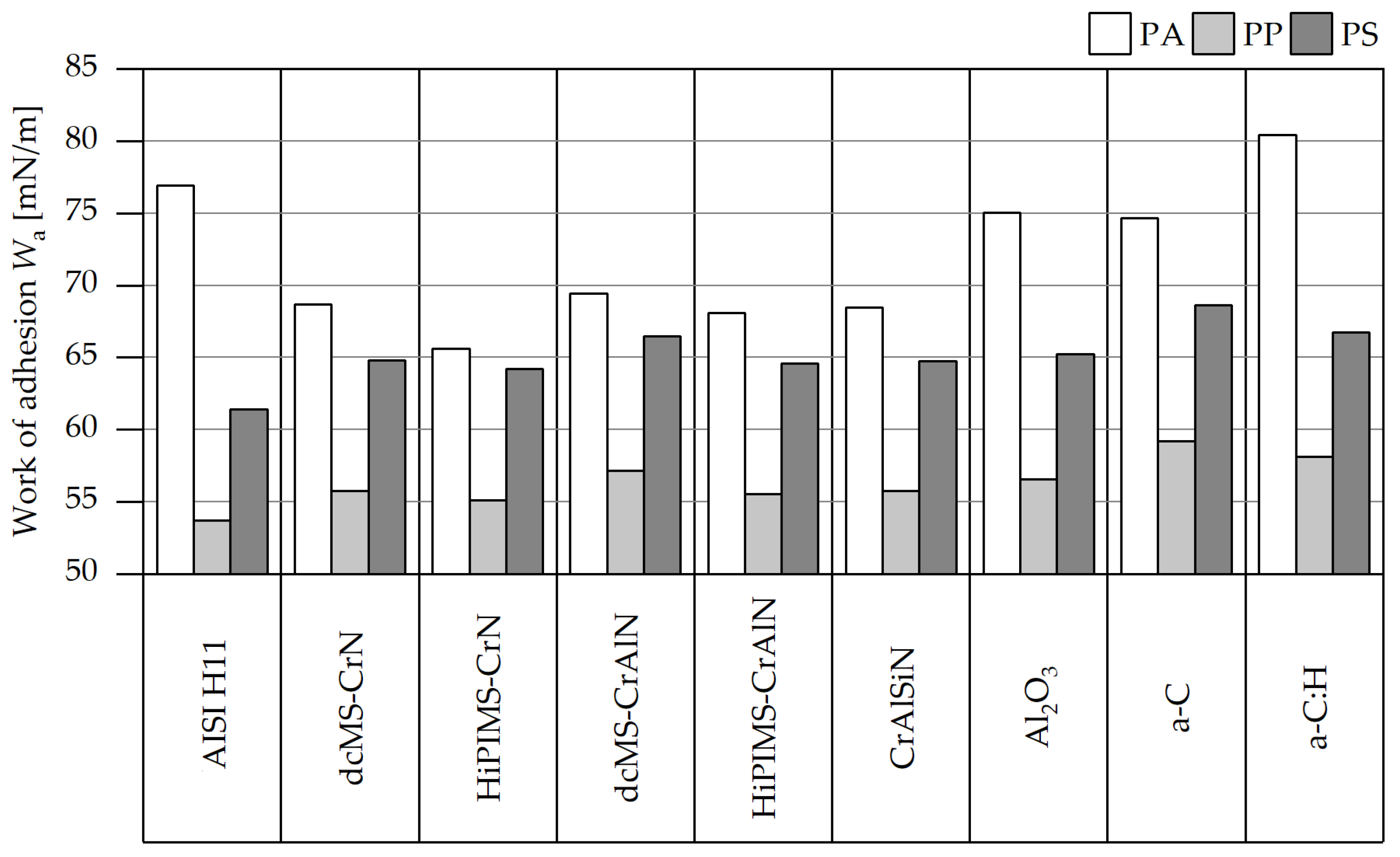
3.2. Surface Free Energy and Work of Adhesion

In order to analyze the surface free energy of the different surface systems, the static contact angles were measured with five different testing liquids (see Table 5). It is noticeable that the standard deviation does not exceed 3° and thus fulfills the recommendation according DIN 55660-2 [22]. The disperse and polar components of the surface energies were calculated based on the results in accordance with the method by OWRK. The results are visualized in Figure 5. It is noticeable that all PVD films, with exception of the a-C:H film, are marked by lower free surface energies than the uncoated steel material with a value of 32.91 mN/m. Within this context, the disperse component of 13.83 mN/m was the lowest of all surface systems, whereas the polar amount of 14.58 mN/m was the highest value. The second highest polar surface energy was achieved by the a-C:H film with a value of 12.44 mN/m. The high polarity of the hydrogenated carbon layer was in good agreement with results reported by Bobzin et al., who determined a polar amount of 15 mN/m and a disperse component of 27.9 mN/m for a plasma assisted chemical vapor deposition (PACVD) deposited a-C:H film [31]. Moreover, the Al2O3 film also had a high value for the polar component with 7.53 mN/m, but the total surface free energy was 29.68 mN/m and, thus, was at the same level as the a-C layer with a value of 29.71 mN/m. The Cr-based nitrides were distinguished by surface energies in the range of 24.45 and 26.60 mN/m. Consequently, they had the lowest values among all surface systems. The polar fraction was, in particular, significantly lower in comparison to the other PVD films and the uncoated AISI H11. The values of the polar surface energy ranged between 1.18 and 2.48 mN/m. The dcMS-CrN and HiPIMS-CrN had surface energies of 25.63 and 24.45 mN/m, respectively. For an unspecified CrN film, Lugscheider et al. reported a surface free energy of approximately 38 mN/m, which is higher than the determined values for the present films [32]. However, the polar fraction of 2.48 and 1.18 mN/m of dcMS-CrN and HiPIMS-CrN are similar to the values determined by Lugscheider et al. The surface energies of dcMS-CrAlN and HiPIMS-CrAlN were 26.60 and 25.30 mN/m, respectively, and are, hence, similar to values reported by Bobzin et al. [33]. In their investigation, the amount of Cr and Al was varied and values in the range between 25.64 and 29.07 mN/m were determined, but the polar content was significantly higher ranging from 5.44 to 6.79 mN/m. Moreover, they did not observe any dependence of the Al concentration on the surface free energy, which correlates with the surface energies of the Al-free CrN films and the CrAlN systems as well. However, the low surface energies of the Cr-based nitrides in contrast to the other PVD films can be ascribed to the chemical nature and is probably attributed to the nitrogen content. Theiss reported similar polar surface energies for CrAlN films with different chemical compositions, which were deposited by means of dcMS, mfMS, and HiPIMS as in this investigation [34]. However, the disperse components were considerably higher, so that values of up to 40 mN/m were obtained for the total surface free energy. Furthermore, Theiss investigated the surface free energy of AISI 420 steel and observed a reduced polar component. According to X-ray photoelectron spectroscopy (XPS) measurements, this behavior was ascribed to the formation of oxides and carbon bondings in the surface reaction layer as well as of adsorbates on the surface [34].
In order to evaluate the effect of the surface energies on the adhesion behavior of the surface systems with the plastic counterparts, the work of adhesion, W a , was determined using Equation (1). The work of adhesion of the AISI H11 steel and PVD films is illustrated in Figure 6. For the calculations, the values of disperse and polar surface energies of PA, PP, and PS, were selected according to Erhard (see Table 4) [24]. It is noticeable that both PP and PS have the lowest work of adhesion to the uncoated material. This behavior is ascribed to the fact that these materials are non-polar plastics with a very low fraction of polar surface energy. As the uncoated AISI H11 steel has a lower disperse component than the PVD films, only the disperse surface energy has an impact on the adhesion behavior to non-polar plastics since only a very low proportion of polar bonds can be formed. In the case of polar plastics such as PA, the polar component of the surface energy is more relevant for the adhesion behavior, so that surface systems with a low polar surface energy are marked by a low work of adhesion. In particular, the Cr-based nitrides have the lowest values of polar surface energy and, thus, exhibit the lowest work of adhesion to PA by having values ranging from 65.6 to 69.4 mN/m. These results are in good agreement with the theoretical results of Lugscheider, who ascribes the adhesion behavior of solid surfaces to interactions between polar and disperse surface energies [32]. As a consequence, a non-polar surface is only influenced by the disperse fraction. Moreover, the calculated results were consistent with observations made by Theiss. In his work, the work of adhesion of PE and PP was not reduced by CrAlN films when compared to the uncoated AISI 420 steel [34]. However, a significant reduction of the adhesion was reported for the polar polymethyl methacrylate (PMMA). With regard to the friction behavior, it is expected that the work of adhesion of the surface systems to the plastic counterpart will have an impact on the adhesion component of the friction.

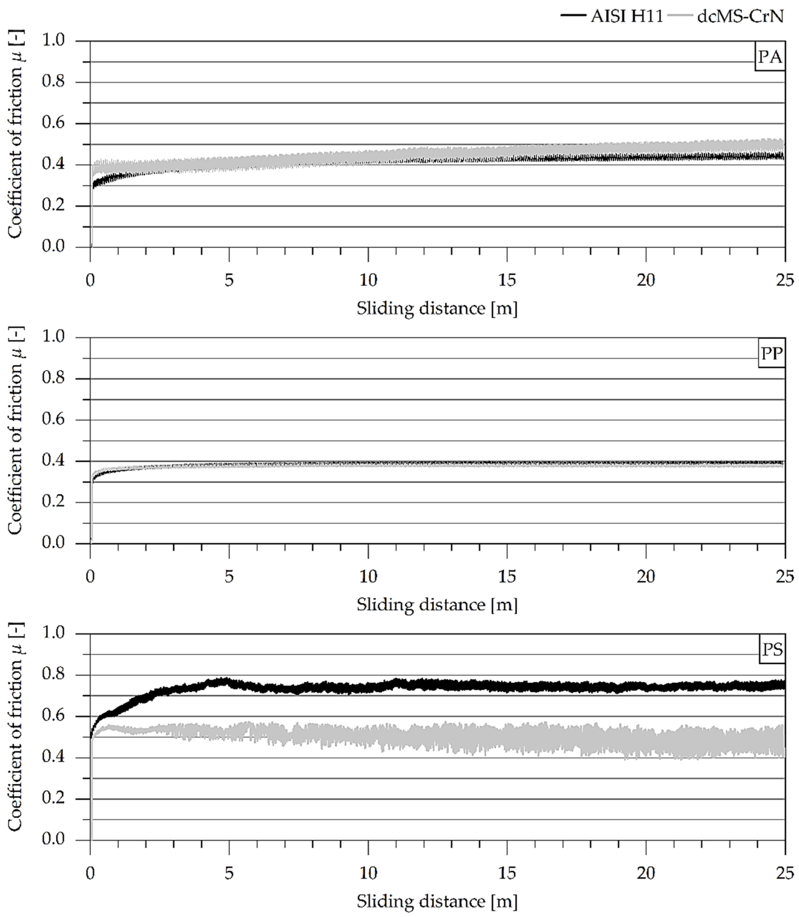
3.3. Tribological Properties

The friction behavior of the uncoated steel and PVD films was analyzed by means of tribometer tests in a ball-on-disc setup. The determined coefficients of friction are illustrated in Figure 7. With exception of the uncoated steel, it is noticeable that PS leads to the highest friction for all PVD films when compared to PA and PP. This behavior is in agreement with the values determined by Hellerich et al., who reported a similar friction behavior of the three plastic counterparts against steel, even though the steel surface had a roughness, Rz, of 2 µm, which is, hence, higher than the roughness profile of the PVD films [35]. When sliding against PA and PS, the uncoated steel material had higher coefficients of friction of 0.78 ± 0.05 and 0.72 ± 0.03 than the PVD films. In the case of PP, the steel material was also distinguished by a higher friction when compared to most PVD films. The Al2O3 film exhibited relatively high coefficients of friction 0.55 ± 0.03, 0.53 ± 0.04, and 0.58 ± 0.03 for PA, PP, and PS, respectively. This high friction for uncoated steel is ascribed to the low roughness values, which lead to an increase of the adhesive component of friction and, thus, to higher coefficients of friction [36]. Furthermore, a higher coefficient of friction against PA when compared to dcMS-CrAlN was observed for the HiPIMS-CrAlN film. However, the work of adhesion was slightly lower for HiPIMS-CrAlN than for dcMS-CrAlN, so that the topography of the surfaces further affects the friction behavior, since the HiPIMS variant has a higher roughness. The friction against plastic components mainly consists of a deformative and adhesive component. Therefore, it is also necessary to analyze the influence of the roughness profile of the surface systems on the coefficient of friction.
The coefficient of friction was plotted against the mean roughness depth, Rz, as illustrated in Figure 8 for a better understanding of the correlation between friction behavior and roughness profile. The σ confidence band and σ prediction band of the regression line were also included. The tendency of a slightly higher friction was observed for the surface systems with a higher surface roughness. A similar trend was observed when plotting against the arithmetic mean roughness, Ra. This behavior was particularly noted for PS. However, it is worthwhile mentioning that some PVD systems do not fully follow this trend for PA and PP by being outside the range of the regression line. This was particularly noted for PA, which is characterized by a broad range of the σ confidence band and σ prediction band. It is concluded that the friction behavior of the surface systems is essentially influenced by the adhesive mechanisms. The adhesive friction component decreases with an increasing surface roughness, whereas the deformative component increases steadily [37]. However, the deformative friction component is not significant in this roughness region as the coefficient of friction does not significantly increase with higher roughness values of the surfaces. Therefore, the adhesive component is the dominant factor for the friction behavior of the PVD films.
As the adhesive component was identified as decisive for the friction behavior, the coefficient of friction was also plotted against the work of adhesion for PA, PP, and PS (see Figure 9). In case of PA and PP, it was observed that a higher work of adhesion leads to higher coefficients of friction, which is ascribed to the increase of the adhesive friction component. This behavior is in good agreement with the study by Bagcivan et al., who investigated the adhesion and tribological behavior of CrAlON films against Plexiglas [12]. They noted lower coefficients of friction for CrAlON films with lower adhesion against Plexiglas. However, this trend was not seen for PS as an opposite relation was observed. In this case, the friction decreases with an increasing work of adhesion. In order to understand this phenomenon, the wear behavior of the PA, PP, and PS balls was investigated by determining the wear coefficient. The determined wear coefficients of the balls are given in Figure 10. It is noticeable that the PS balls are exposed to a higher wear in the tribometer tests than the PA and PP balls. In the tribometer tests, an agglomeration of wear debris from the PS balls along the wear track was observed. It is assumed that the PS wear debris had a friction-reducing effect and resulted in a lower coefficient of friction despite the higher work of adhesion. This behavior was reported by Thorp, who observed the formation of a transfer film of polytetrafluoroethylene (PTFE) and ultra-high molecular weight polyethylene (UHMWPE) on the steel surfaces during dry sliding, which leads to reduced coefficients of friction [38]. A similar mechanism is expected, as adhered particles were observed on the surface, after the tribometer tests with PS balls, whereas no material transfer was observed for PA and PP. However, the uncoated surface is an exception, which does not cause a high wear of the PS balls. In this case, the wear coefficient of the PS balls was comparable to the wear coefficients of PA and PP. This behavior is ascribed to several reasons, which are related to the roughness profile and to the work of adhesion of the uncoated AISI H11. On the one hand, the uncoated steel material had a mean roughness depth, Rz, of 34.8 ± 4.4 nm and a low hardness of 7.03 ± 0.31 GPa, which in combination do not lead to abrasive wear mechanisms in contrast to the rougher and harder PVD films. On the other hand, the work of adhesion for both the AISI H11 and PS was 61.42 mN/m and thereby significantly lower in comparison to the PVD films. The adhesion strength was therefore too low to induce adhesively induced wear.
The curves of the coefficient of friction are exemplarily shown in Figure 11 for the uncoated AISI H11 and the dcMS-CrN film against PA, PP, and PS for a comprehensive understanding of the wear mechanisms of the plastic balls. When comparing the friction behavior of the uncoated steel and the dcMS-CrN film against PS, it is noticeable that the curve for dcMS-CrN is marked by a strong stick–slip effect, which is the explanation for the strong wear of the PS balls. Moreover, the stick–slip effect increases with larger sliding distance due to an increased wear volume of the PS balls. In contrast, the curves for the tribometer tests with PA and PS remain almost constant with an increasing sliding distance. This can be ascribed to the low wear of the PA and PS balls. Regarding the wear behavior, it is worth mentioning that the surface systems did not show any sign of abrasive wear, a fact that is attributed to the high hardness difference between the friction partners. Only an adhesive material transfer of the worn plastic balls was observed on the surfaces. The dimensions of the transfer depend on the wear coefficients of the balls.

4. Conclusions

The cause–effects relationship between the surface roughness and surface free energy of PVD films on the friction behavior against PA, PP, and PS was investigated. Besides the uncoated AISI H11 steel, several film systems, consisting of dcMS- and HiPIMS-sputtered CrN and CrAlN, as well as CrAlSiN, Al2O3, a-C, and a-C:H, were systematically analyzed with regard to their surface free energy and tribological properties. Among the surface systems, differences concerning the surface free energy and, in particular, the polar component, were observed. The Cr-based nitrides exhibit the lowest surface energies with a very low polar content. Based on the results of the surface free energy, the work of adhesion was calculated for PA, PP, and PS. It was shown that the disperse component of the surface systems is decisive for the work of adhesion with the non-polar PP and PS, since no polar interactions occur on the surface. In contrast to the polar PA, the polar component is more significant than the dispersive component, so that the Cr-based nitrides with low polar surface energy are marked by the lowest values. In tribometer tests, an influence of the surface roughness and the work of adhesion on the friction behavior was identified. The trend of lower coefficients of friction with slightly higher roughness was observed, in particular for PS. In contrast, a higher work of adhesion results in higher coefficients of friction when sliding against PA and PP. However, a contrary relationship was observed in case of PS, which is ascribed to the formation of a transfer film due to the high wear of PS balls. Therefore, a dependence of both properties, the roughness and the work of adhesion, on the friction behavior of PVD films against the plastic counterparts was shown.

Author Contributions

Conceptualization, W.T., N.F.L.D., D.S. and N.G; Methodology, N.F.L.D., D.S. and N.G.; Investigation, N.F.L.D., D.S. and N.G.; Writing—Original Draft, N.F.L.D. and N.G.; Writing—Review and Editing, W.T. and D.S.; Visualization, N.F.L.D. and N.G.; Supervision, W.T.

Funding

This research received no external funding.

Acknowledgments

The authors acknowledge the financial support by the German Research Foundation and TU Dortmund University within the funding program “Open Access Publishing”. The authors wish to express their gratitude to Dirk Biermann and Eugen Krebs from the Institute of Machining Technology (TU Dortmund University) for providing the confocal 3D microscope and Jörg C. Tiller and Christian Krumm of the Biomaterials and Polymer Science Department (TU Dortmund University) for providing the contact angle measuring system.

Conflicts of Interest

The authors declare no conflict of interest.

References

  1. Zheng, R.; Tanner, R.I.; Fan, X.-J. Injection Molding. Integration of Theory and Modeling Methods; Springer Science & Business Media: Berlin, Germany, 2011; ISBN 978-3-642-21262-8. [Google Scholar]
  2. Gramann, P.J.; Osswald, T.A. Introduction. In Injection Molding Handbook, 2nd ed.; Osswald, T.A., Turng, L.-S., Gramann, P.J., Eds.; Springer Science & Business Media: Berlin, Germany, 2008; pp. 1–18. ISBN 978-3-446-40781-7. [Google Scholar]
  3. Rosato, D.V.; Rosato, D.V.; Rosato, M.G. Injection Molding Handbook, 3rd ed.; Springer US: Boston, MA, USA, 2000; ISBN 9781461370772. [Google Scholar]
  4. Kerkstra, R.; Brammer, S. Injection Molding Advanced Troubleshooting Guide; Carl Hanser Verlag: Munich, Germany, 2018; ISBN 9781569906453. [Google Scholar]
  5. Kazmer, D. Injection Mold Design Engineering, 2nd ed.; Carl Hanser Verlag: Munich, Germany, 2016; ISBN 978-1-56990-570-8. [Google Scholar]
  6. Sakai, T.; Kikugawa, K. Injection Molding Machinery and Systems. In Injection Molding: Technology and Fundamentals; Kamal, M.R., Agassant, J.-F., Eds.; Carl Hanser Verlag: Munich, Germany, 2009; pp. 73–131. ISBN 978-3-446-41685-7. [Google Scholar]
  7. Bienk, E.J.; Mikkelsen, N.J. Application of advanced surface treatment technologies in the modern plastics moulding industry. Wear 1997, 207, 6–9. [Google Scholar] [CrossRef]
  8. Bobzin, K.; Nickel, R.; Bagcivan, N.; Manz, F.D. PVD—Coatings in Injection Molding Machines for Processing Optical Polymers. Plasma Process. Polym. 2007, 4, S144–S149. [Google Scholar] [CrossRef]
  9. Silva, F.J.G.; Martinho, R.P.; Baptista, A.P.M. Characterization of laboratory and industrial CrN/CrCN/diamond-like carbon coatings. Thin Solid Films 2014, 550, 278–284. [Google Scholar] [CrossRef]
  10. Silva, F.; Martinho, R.; Andrade, M.; Baptista, A.; Alexandre, R. Improving the wear resistance of moulds for the injection of glass fibre–reinforced plastics using PVD coatings: A comparative study. Coatings 2017, 7, 28. [Google Scholar] [CrossRef]
  11. D’Avico, L.; Beltrami, R.; Lecis, N.; Trasatti, S. Corrosion behavior and surface properties of PVD coatings for mold technology applications. Coatings 2019, 9, 7. [Google Scholar] [CrossRef]
  12. Bagcivan, N.; Bobzin, K.; Brögelmann, T.; Kalscheuer, C. Development of (Cr,Al) ON coatings using middle frequency magnetron sputtering and investigations on tribological behavior against polymers. Surface Coat. Technol. 2014, 260, 347–361. [Google Scholar] [CrossRef]
  13. Bobzin, K.; Grundmeier, G.; Brögelmann, T.; los Arcos, T.; Wiesing, M.; Kruppe, N.C. Nitridische und oxinitridische HPPMS-Beschichtungen für den Einsatz in der Kunststoffverarbeitung (Teil 2). Vakuum Forschung Praxis 2017, 29, 24–28. [Google Scholar] [CrossRef]
  14. Paints and Varnishes-Pull-off Test for Adhesion (ISO 4624:2016), German Version EN ISO 4624:2016; DIN German Institute for Standardization: Berlin, Germany, 2016.
  15. Sasaki, T.; Koga, N.; Shirai, K.; Kobayashi, Y.; Toyoshima, A. An experimental study on ejection forces of injection molding. Precis. Eng. 2000, 24, 270–273. [Google Scholar] [CrossRef]
  16. Burkard, E.; Walther, T.; Schinköthe, W. Influence of mold wall coatings while demoulding in the injection molding process. Stuttg. Kunststoff Kolloquium 1999, 16, 1–8. [Google Scholar]
  17. Kobayashi, Y.; Shirai, K.; Sasaki, T.; Kobayashi, Y.; Shirai, K.; Sasaki, T. Relationship between core surface roughness and ejection force for injection molding. J. Jpn. Soc. Prec. Eng. 2001, 67, 510–514. [Google Scholar] [CrossRef]
  18. Mitschang, P.; Schledjewski, R.; Schlarb, A.K. Molds for continuos fibre reinforced polymer composites. In Mold-Making Handbook, 3rd ed.; Mennig, G., Stoeckhert, K., Eds.; Carl Hanser Verlag: Munich, Germany, 2013; pp. 200–238. ISBN 978-1-56990-446-6. [Google Scholar]
  19. Hoffmann, F. Beitrag zur Charakterisierung des tribologischen Verhaltens von Diamantähnlichen Kohlenstoffschichten für die Holzbearbeitung. Ph.D. Thesis, TU Dortmund University, Dortmund, Germany, 2012. [Google Scholar]
  20. Geometrical Product Specifications (GPS)–Surface Texture: Profile Method–Terms, Definitions and Surface Texture Parameters (ISO 4287:1997 + Cor 1:1998 + Cor 2:2005 + Amd 1:2009), German Version EN ISO 4287:1998 + AC:2008 + A1:2009; DIN German Institute for Standardization: Berlin, Germany, 2010.
  21. Geometrical Product Specifications (GPS)-Surface Texture; Profile Method-Rules and Procedures for the Assessment of Surface Texture (ISO 4288:1996), German Version EN ISO 4288:1997; DIN German Institute for Standardization: Berlin, Germany, 1998.
  22. Paints and Varnishes–Wettability–Part 2: Determination of the Free Surface Energy of Solid Surfaces by Measuring the Contact Angle, German Version DIN 55660-2; DIN German Institute for Standardization: Berlin, Germany, 2011.
  23. Zhang, J. Work of adhesion and work of cohesion. In Encyclopedia of Tribology; Wang, Q.J., Chung, Y.-W., Eds.; Springer US: Boston, MA, USA, 2013; pp. 4127–4132. ISBN 978-0-387-92896-8. [Google Scholar]
  24. Erhard, G. Designing with Plastics; Carl Hanser Verlag: Munich, Germany, 2006; ISBN 978-3-446-22590-9. [Google Scholar]
  25. Barshilia, H.C.; Selvakumar, N.; Deepthi, B.; Rajam, K.S. A comparative study of reactive direct current magnetron sputtered CrAlN and CrN coatings. Surf. Coat Technol. 2006, 201, 2193–2201. [Google Scholar] [CrossRef]
  26. Lin, J.; Mishra, B.; Moore, J.J.; Sproul, W.D. Microstructure, mechanical and tribological properties of Cr1−xAlxN films deposited by pulsed-closed field unbalanced magnetron sputtering (P-CFUBMS). Surf. Coat Technol. 2006, 201, 4329–4334. [Google Scholar] [CrossRef]
  27. Ehiasarian, A.; Münz, W.D.; Hultman, L.; Helmersson, U.; Petrov, I. High power pulsed magnetron sputtered CrNx films. Surf. Coat Technol. 2003, 163–164, 267–272. [Google Scholar] [CrossRef]
  28. Rafaja, D.; Dopita, M.; Růžička, M.; Klemm, V.; Heger, D.; Schreiber, G.; Šímac, M. Microstructure development in Cr–Al–Si–N nanocomposites deposited by cathodic arc evaporation. Surf. Coat Technol. 2006, 201, 2835–2843. [Google Scholar] [CrossRef]
  29. Tillmann, W.; Lopes Dias, N.F.; Stangier, D. Influence of plasma nitriding pretreatments on the tribo-mechanical properties of DLC coatings sputtered on AISI H11. Surface Coat. Technol. 2019, 357, 1027–1036. [Google Scholar] [CrossRef]
  30. Tillmann, W.; Lopes Dias, N.F.; Stangier, D.; Maus-Friedrichs, W.; Gustus, R.; Thomann, C.A.; Moldenhauer, H.; Debus, J. Improved adhesion of a-C and a-C: H films with a CrC interlayer on 16MnCr5 by HiPIMS-pretreatment. Surface Coat. Technol. 2019, 375, 877–887. [Google Scholar] [CrossRef]
  31. Bobzin, K.; Bagcivan, N.; Theiss, S.; Yilmaz, K. Plasma coatings CrAlN and a-C: H for high efficient power train in automobile. Surface Coat. Technol. 2010, 205, 1502–1507. [Google Scholar] [CrossRef]
  32. Lugscheider, E.; Bobzin, K. The influence on surface free energy of PVD-coatings. Surface Coat. Technol. 2001, 142, 755–760. [Google Scholar] [CrossRef]
  33. Bobzin, K. Benetzungs- und Korrosionsverhalten von PVD-beschichteten Werkstoffen für den Einsatz in umweltverträglichen Tribosystemen. Ph.D. Thesis, RWTH Aachen, Aachen, Germany, 2000. [Google Scholar]
  34. Theiss, S. Analyse gepulster Hochleistungsplasmen zur Entwicklung neuartiger PVD-Beschichtungen für die Kunststoffverarbeitung. Ph.D. Thesis, RWTH Aachen, Aachen, Germany, 2013. [Google Scholar]
  35. Hellerich, W.; Harsch, G.; Haenle, S. Werkstoff-Führer Kunststoffe. Eigenschaften, Prüfungen, Kennwerte; Carl Hanser Verlag: Munich, Germany, 2010; ISBN 978-3-446-42436-4. [Google Scholar]
  36. Goryacheva, I.G. Contact Mechanics in Tribology; Springer Science & Business Media: Berlin, Germany, 2011; ISBN 978-90-481-5102-8. [Google Scholar]
  37. Brinksmeier, E.; Riemer, O.; Twardy, S. Tribological behavior of micro structured surfaces for micro forming tools. Int. J. Mach. Tools Manuf. 2010, 50, 425–430. [Google Scholar] [CrossRef]
  38. Thorp, J.M. Tribological properties of selected polymeric matrix composites against steel surfaces. In Friction and Wear of Polymer Composites; Friedrich, K., Ed.; Elsevier Science: Amsterdam, The Netherlands, 1986; pp. 89–135. ISBN 9780444597113. [Google Scholar]
Figure 1. Scanning electron microscope (SEM) micrographs of the morphology of the physical vapor deposition (PVD) films.
Coatings 09 00588 g001
Figure 2. Schematic representation of the experimental procedure.
Coatings 09 00588 g002
Figure 3. SEM micrographs of the topography of the PVD films.
Coatings 09 00588 g003
Figure 4. Arithmetical mean roughness, Ra, and mean roughness depth, Rz, of the AISI H11 steel and the PVD films.
Coatings 09 00588 g004
Figure 5. Surface free energy, σs, with corresponding disperse and polar components of AISI H11 steel and PVD films.
Coatings 09 00588 g005
Figure 6. Work of adhesion, Wa, of the AISI H11 steel and PVD films with PA, polypropylene (PP), and polystyrene (PS).
Coatings 09 00588 g006
Figure 7. Coefficients of friction of the AISI H11 steel and PVD films.
Coatings 09 00588 g007
Figure 8. Correlation between mean roughness depth, Rz, and the coefficient of friction of the AISI H11 steel and the PVD films against PA, PP, and PS.
Coatings 09 00588 g008
Figure 9. Correlation between work of adhesion Wa and the coefficient of friction of the AISI H11 steel and PVD films against PA, PP, and PS.
Coatings 09 00588 g009
Figure 10. Wear coefficients of the PA, PP, and PS balls after sliding against the AISI H11 steel and PVD films.
Coatings 09 00588 g010
Figure 11. Exemplary curves of the coefficients of friction of the AISI H11 steel and dcMS-CrN against PA, PP, and PS.
Coatings 09 00588 g011
Table 1. Deposition parameters of the PVD films.
Film SystemdcMS- CrNHiPIMS- CrNdcMS- CrAlNHiPIMS- CrAlNCrAlSiNAl2O3a-C (Top Layer)a-C:H (Top Layer)
Sputter modedcMSHiPIMSdcMSHiPIMSdcMSmfMSmfMSmfMS
Target × cathode power (kW) or voltage (V)2 Cr × 4.0 kW2 Cr × 4.0 kW2 AlCr20 × 5.0 kW2 AlCr20 × 7.0 kW2 AlCr24 × 5.0 kW
1 Cr × 1.0 kW
1 Si × 2.0 kW
2 Al × 410 V2 C × 3 kW2 C × 3 kW
Pulse frequency (Hz)1000600
Pulse duration (µs)5050
Mid frequency (kHz)502020
Pressure (mPa)400400500500500control300300
Ar flow (sccm)30030012080120300controlcontrol
Kr flow (sccm)50501804080
N2 flow (sccm)controlcontrolcontrolcontrolcontrol
O2 flow (sccm)60
C2H2 flow (sccm)35
Bias voltage (−V)90100120150120100130130
Deposition time (s)10.00020.00021.00020.00021.2007.20018.00012.500
dcMS—direct current magnetron sputtering; HiPIMS—high-power impulse magnetron sputtering; a-C—hydrogen-free amorphous carbon; a-C:H—hydrogenated amorphous carbon; control—controlled.
Table 2. Overview of the chemical composition, film thickness, hardness, and elastic modulus of the used PVD Films.
Film SystemChemical Composition [at.%]Hardness [GPa]Elastic Modulus [GPa]
CrAlSiNO
dcMS-CrN52.4 ± 0.847.6 ± 0.822.9 ± 1.3301.8 ± 17.7
HiPIMS-CrN64.0 ± 1.136.0 ± 1.124.6 ± 1.7332.4 ± 15.8
dcMS-CrAlN12.3 ± 0.536.0 ± 1.051.8 ± 1.526.7 ± 2.2306.9 ± 14.4
HiPIMS-CrAlN33.2 ± 1.014.5 ± 0.252.4 ± 1.233.3 ± 4.1354.6 ± 36.7
dcMS-CrAlSiN15.5 ± 0.624.3 ± 0.78.1 ± 0.252.2 ± 1.427.6 ± 1.7291.5 ± 11.5
Al2O345.0 ± 0.255.0 ± 0.214.9 ± 0.9193.4 ± 7.1
a-CHydrogen-free amorphous carbon20.5 ± 1.5190.7 ± 8.4
a-C:HHydrogenated amorphous carbon16.4 ± 1.0148.5 ± 6.1
Table 3. Disperse and polar component of the surface energy of the test liquids.
Test Liquid Surface   Energy ,   σ l   [ mN / m ] Disperse   Component ,   σ l D   [ mN / m ] Polar   Component ,   σ l P   [ mN / m ]
Distilled water72.821.851
Ethylene glycol482919
Dimethylformamide37.332.44.9
1-Octanol21.621.60
1-Decanol28.522.26.3
Table 4. Disperse and polar component of the surface energy of the plastic counterparts according to Erhard [20].
Plastic Counterpart Surface   Energy ,   σ b   [ mN / m ] Disperse   Component ,   σ b D   [ mN / m ] Polar   Component ,   σ b P   [ mN / m ]
PA47.536.810.7
PP31.230.50.7
PS42.041.40.6
Table 5. Arithmetical mean of the measured static contact angles.
Surface SystemStatic Contact Angle [°]
WaterEthylene GlycolDimethylformamide1-Octanol1-Decanol
Uncoated
AISI H11
69.4 ± 1.759.6 ± 2.0732.6 ± 2.12.0 ± 2.114.4 ± 1.8
dcMS-CrN93.2 ± 0.877.2 ± 0.835.2 ± 1.611.8 ± 0.821.8 ± 1.8
HiPIMS-CrN100.2 ± 0.875.6 ± 1.150.4 ± 1.713.2 ± 1.526.4 ± 2.5
dcMS-CrAlN94.6 ± 1.175.0 ± 2.634.2 ± 1.909.6 ± 2.1
HiPIMS-CrAlN94.6 ± 1.375.2 ± 0.842.0 ± 1.64.8 ± 1.924.4 ± 1.5
CrAlSiN94.4 ± 1.872.8 ± 1.941.4 ± 1.77.2 ± 1.825.4 ± 2.3
Al2O381.2 ± 1.659.6 ± 1.128.4 ± 1.1012.8 ± 0.8
a-C88.2 ± 1.858.8 ± 2.315.4 ± 1.700.8 ± 1.1
a-C:H73.2 ± 1.839.4 ± 0.910.4 ± 1.501.8 ± 1.8

