Article

Scale Formation and Degradation of Diffusion Coatings Deposited on 9% Cr Steel in Molten Solar Salt

DECHEMA-Forschungsinstitut, Theodor-Heuss-Allee 25 60486 Frankfurt (Main), Germany
*
Author to whom correspondence should be addressed.
Coatings 2019, 9(10), 687; https://doi.org/10.3390/coatings9100687
Submission received: 27 September 2019 / Revised: 16 October 2019 / Accepted: 18 October 2019 / Published: 22 October 2019
(This article belongs to the Special Issue Surfaces and Interfaces for Renewable Energy)

Abstract

:
The employment of ferritic-martensitic steels e.g., P91, as structural materials in concentrated solar power (CSP) plants can significantly increase cost-efficiency. However, their application is strongly restricted by their lower corrosion resistance in molten nitrates, compared to austenitic steels or Ni-based alloys. In this study, Cr-, Al-, and Cr/Al-diffusion coatings were deposited on P91 via pack cementation in order to improve its scaling behavior in molten solar salt (MSS). The corrosion behavior of coated specimens was investigated with respect to uncoated P91 in MSS at 600 °C for up to 1000 h. The exposure in MSS resulted in a thick, highly porous, and multi-layered oxide scale on uncoated P91 consisting of hematite, magnetite, and sodium ferrite. On the other hand, the scale grown on the chromized P91 comprised of a thin Cr-rich inner layer, which shifted breakaway to prolonged exposure durations. The aluminized specimens both formed very thin, highly protective alumina scales with localized protrusions.

1. Introduction

With the ultimate goal of reducing CO2 emissions, solar energy has been qualified as one of the most prolific green energy technologies (owing to the abundance of sunlight and the “climate neutral” nature of the related energy conversion methods). Along with photovoltaics (PV), concentrated solar power (CSP) technology has received considerable interest in terms of research and development activities, leading to its commercialization over the past decades [1,2]. CSP technology utilizes programmable heliostats, which concentrate solar irradiation to a so-called receiver. The focused solar energy is then converted to thermal energy and subsequently to electricity via a conventional steam turbine [3,4,5].
CSP plants can be operated with or without thermal energy storage (TES) systems; the former enabling improved dispatchability for electricity generation. Hence, the current development trend focuses on CSP plants with TES (e.g., Crescent Dunes Solar Power Plant, USA) by the utilization of heat transfer fluids (HTF) with high thermal capacities. Molten nitrate salts, particularly the non-eutectic mixture of 60 wt.% NaNO3-40 wt.% KNO3 (known as “solar salt”) are qualified as state-of-the-art HTF for CSP applications owing to their beneficial thermophysical properties for TES [1,4,6,7,8,9,10,11]. The minimum temperature of the operation range of solar salt (around 290 °C) is limited by the liquidus temperature (lying around 240 °C) to avoid solidification of the salt, since continuous molten salt flow is required [2,12]. On the other hand, the maximum temperature of the operation range is restricted by the thermal decomposition of nitrate initially to nitrite (Reaction 1) and further to nitrous oxides (Reaction 2), which is accelerated at temperatures exceeding 600 °C [1,8,10,13].
NO 3 NO 2 + 1 2 O 2 ( g )
2 NO 2 NO 2 ( g ) + NO ( g ) + O 2
These decomposition reactions alter the salt composition by changing the nitrate/nitrite ratio and thus affect the thermophysical properties, as studied in [14]. More importantly, both decomposition reactions result in an increased concentration of oxidizing agents in the salt melt, which is basically an ionic electrolyte at higher temperatures and conveys oxidizing agents to metallic surfaces, while metal cations can be dissolved into the salt melt [2,10,13]. For instance, Cr is a stable oxide former for various industrial applications; however, Cr cations present in the Cr-rich oxide scales can further oxidize and form chromate or dichromate species (e.g., via Reaction 3 [7,15]) that are highly soluble in the molten salt [9,11,16]. The formation of these species not only increases the extent of Cr-depletion, but also generate major environmental and health issues due to chromates being highly toxic [6].
Cr 2 O 3 + 2 O 2 + 3 2 O 2 ( g ) 2 CrO 4 2
Furthermore, commercial solar salt contains a wide variety of impurities, such as chlorides and sulfates, which can increase the corrosion rate, as shown in [17,18]. Due to the above stated reasons, the corrosion resistance of structural materials employed in the receiver tubing system and the hot storage tank is a decisive factor for plant design and lifetime [4,6,9,10,11,19].
Another important obstacle currently restricting the wider application of the CSP technology is its lower cost-efficiency with respect to other renewable energy sources e.g., PV, hydro- or wind-power [5]. Employment of cheaper alloys as structural materials can be a very efficient method to reduce costs in CSP plants. The corrosion behavior of low Cr-steels, austenitic steels and Ni-based alloys in molten nitrate salts at a wide temperature range has been investigated in different studies [2,10,13,14,17,18,20,21,22], which showed higher corrosion resistance for austenitic steels and Ni-based alloys compared to ferritic-martensitic steels. Notwithstanding their high corrosion resistance, employment of austenitic steels or Ni-based alloys significantly increases the cost of structural materials in CSP plants. For instance, the unit price of the Ni-based alloy 617 is roughly nine times higher than that of the grade 91 steel [23]. Corrosion resistance of ferritic-martensitic steels in molten nitrate salt can be increased via diffusion coatings, thereby enabling their employment in the receiver panels. Recent studies showed that aluminide coatings can significantly increase the corrosion resistance of ferritic-martensitic steels in molten nitrate salts by forming Al-rich protective oxide scales [6,12,24,25,26]. This study aims at the elucidation of corrosion and protection mechanisms by identifying the chemical composition of oxide scales grown on uncoated and diffusion coated ferritic-martensitic steels in molten solar salt (MSS) using complementary characterization methods. For this purpose, Cr-, Al- and Cr/Al-diffusion coatings were manufactured on grade 91 steel, which is widely employed in heat exchanger systems up to 650 °C [27]. Subsequently, static immersion tests in MSS were conducted at 600 °C. The scaling behavior of coated specimens was investigated and compared to that of uncoated P91 to explore the applicability of diffusion-coated ferritic-martensitic steels as structural materials in CSP systems with TES.

2. Materials and Methods

Ferritic-martensitic steel X10CrMoVNb9-1 (P91/T91) was used as a base material and coated according to the description in the following subsection. Its chemical composition is shown in Table 1:
Coupon specimens of dimensions 20 mm × 10 mm × 3 mm were manufactured using wire cutting and cleansed of native oxides and contamination by means of glass-bead blasting and ultrasonic degreasing in ethanol. All test samples were weighed after every coating step and prior to exposure, respectively. Additionally, their dimensions were measured followed by a calculation of each sample’s individual surface area to finally assess specific weight changes.

2.1. Coating Manufacturing

All coatings were manufactured via the well-established powder pack cementation chemical vapor deposition (CVD) process, which is described in detail elsewhere e.g., in [28,29,30]. Cr- and Al-diffusion coatings were manufactured via single-step processes using the parameters summarized in Table 2, respectively. Cr/Al-diffusion coatings were produced by combining both as a two-step process, similar to the procedure used in [31].

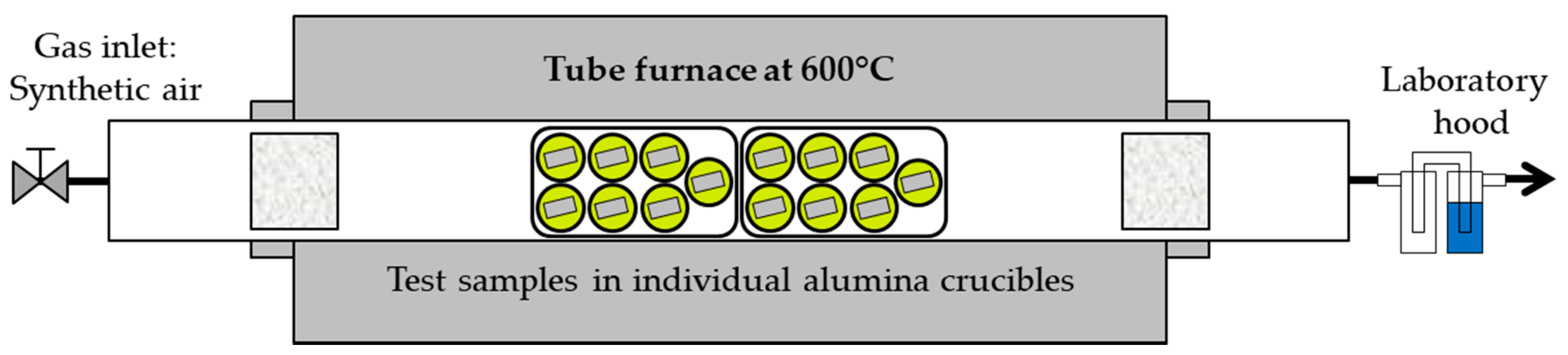
2.2. Exposure in Molten Solar Salt

For the isothermal exposures in molten nitrate, state-of-the-art solar salt consisting of 60 wt.% NaNO3 and 40 wt.% KNO3 was used with initial impurities of 131 ppm Cl and 60 ppm SO42−. Since solar salt with a relatively higher impurity level is lower-priced and thus technically more relevant compared to pure grades, a higher impurity level of 500 ppm for both chloride and sulfate species was investigated in this study. Initially, both components of the solar salt were pre-mixed to yield a 2 kg salt mixture. The targeted impurity level of chloride and sulfate species was then adjusted by adding NaCl and Na2SO4 to the pre-mixed solar salt using a precision (0.01 mg) weighing balance (Mettler Toledo XP205, Columbus, OH, USA). The final salt mixture was then homogenized for 2 h at room temperature using a turbular mixer. The corrosion tests were conducted in a horizontal tube furnace with a test atmosphere of flowing dry synthetic air (4 L/h). A schematic representation of the experimental setup is given in Figure 1. The exposures were carried out following the specifications of ISO 17245:2015 [32] by placing the test specimens in individual cylindrical alumina crucibles, covering them with the salt mixture at room temperature, and heating them to the static test temperature of 600 °C. After each time interval (115, 300 and 1000 h), two samples of the uncoated substrate and of every coating were removed from the hot furnace, cooled to room temperature, and carefully cleaned in warm distilled water.

2.3. Post-Exposure Characterization

Prior to metallographic preparation, all samples were weighed using a precision weighing balance (Mettler Toledo XP205, Columbus, OH, USA). Phase analysis of the test pieces was performed using a Bruker D8 X-ray diffractometer (Billerica, MA, USA) with Cu-K-alpha radiation and a Lynxeye-semiconductor detector.
In order to enhance the contrast between corrosion or oxidation products and the adjacent epoxy resin, the samples were electroplated with Ni prior to mounting in hot resin. Afterwards, cross-sections of all test specimens were prepared by conventional metallographic methods, including grinding with successively finer SiC paper up to 1200 grit and polishing with 3 and 1 µm diamond suspensions. Inspection of the cross sections was carried out with the help of standard micro-analytical methods such as optical light microscopy and complementary scanning electron microscopy (SEM, Philips XL-40, Amsterdam, The Netherlands) analysis as well as electron probe micro-analysis (EPMA, JEOL JXA-8100, Tokyo, Japan). To further assess the composition of the thin oxide scales grown after exposure, Raman spectroscopy analyses (RENISHAW InVia working with a He-Ne laser, 632.8 nm, Wotton-under-Edge, UK) were also conducted.

3. Results and Discussion

3.1. Microstructure of as-deposited Coatings

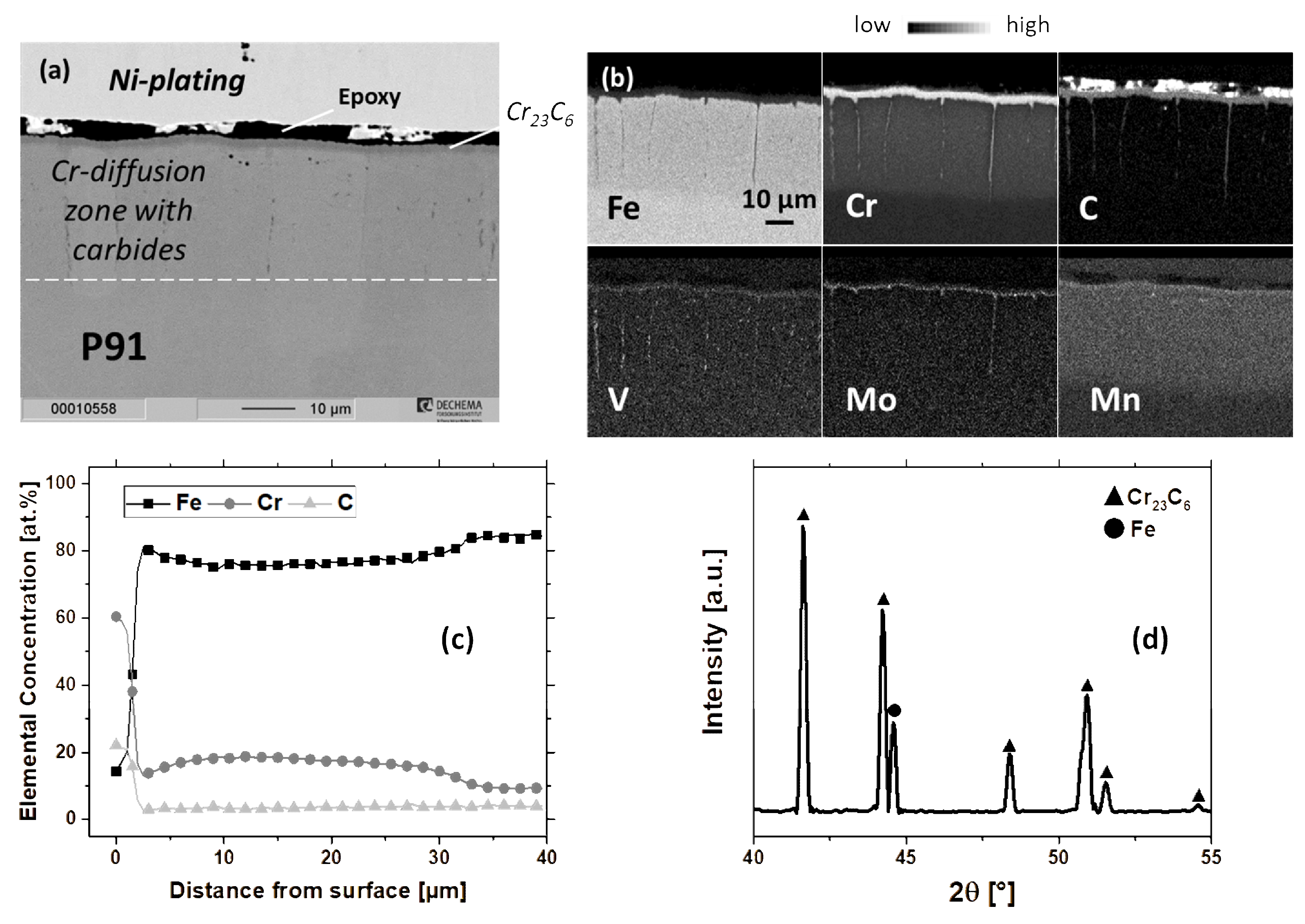
3.1.1. Cr-Diffusion Coating

Figure 2 shows the cross-sectional back-scattered electron (BSE) micrograph, elemental distribution maps, and line scans of Fe, Cr, and C, both acquired by EPMA as well as the X-ray diffraction (XRD) pattern of the Cr-diffusion coated P91. The coating consisted of a thin (3–5 µm) Cr23C6 layer (as identified by the XRD analysis shown in Figure 2d) followed by an approximately 30 µm thick Cr-diffusion zone, which contained an average Cr-concentration of 17 at.% (see Figure 2c). The formation of this Cr23C6 layer can be attributed to outward carbon diffusion from the substrate due to the high Cr activity at the surface [33,34]. In addition, Mn was enriched to an average concentration of 1 at.% (corresponds approximately to 1.1 wt.%) in the Cr-diffusion zone (see Figure 2b), compared to its original concentration in P91 (0.3–0.6 wt.%). The enrichment of Mn can be explained by the utilization of MnCl2 as the activator. Mn evidently diffused to the alloy surface to some extent together with Cr. Within the Cr-diffusion zone, large ferrite grains were formed. The stabilization of ferrite is associated with the Cr-enrichment and reduced carbon content due to the formation of the chromium carbide surface layer. Refractory metal (Cr, V, and Mo) rich carbides were observed at the ferrite grain boundaries (see Figure 2b), as also was highlighted by Meier et al. [35].

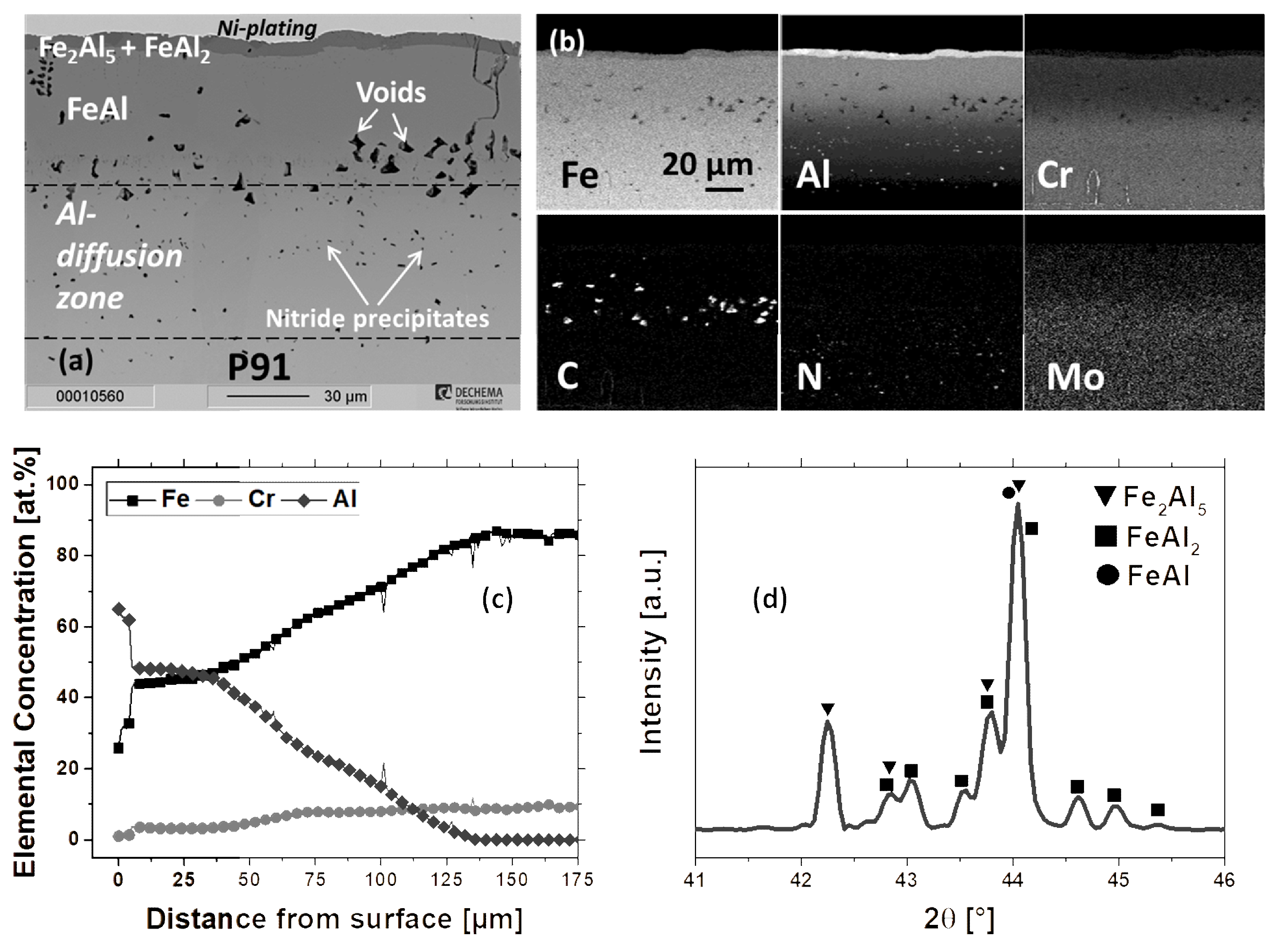
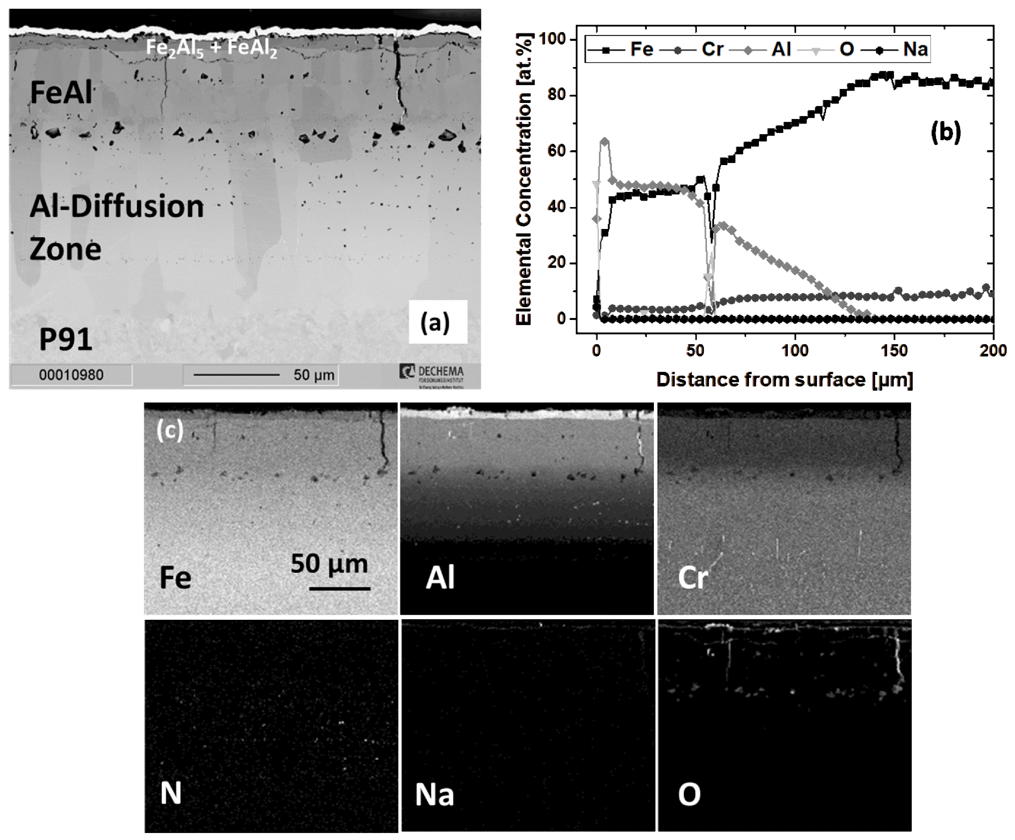
3.1.2. Al-Diffusion Coating

Pack aluminizing at 1000 °C resulted in the formation of different aluminide layers with varying chemical composition and microstructure (see Figure 3). The Al-concentration at the thin (ca. 5 µm) sub-surface layer was determined to be 65 at.% (Figure 3c). Correspondingly FeAl2 and Fe2Al5 phases were identified by the XRD analysis (Figure 3d). Such brittle Al-rich Fe-Al intermetallic phases are usually observed in aluminide coatings manufactured on ferritic steels at lower coating temperatures around 700 °C, provided that pure Al is used as the diffusion element [31,36,37,38]. On the other hand, aluminizing at elevated temperatures (e.g., at 1000 °C and higher) results in the transformation of the Fe2Al5 to FeAl due to the concurrent inward Al and outward Fe diffusion, as further explained in [25,39,40]. Evidently, the selected pack aluminizing parameters in this study involving 1 h dwell at 1000 °C (see Table 2) were not sufficient to transform the Al-rich intermetallic phases to FeAl completely. Together with the insufficient time provided for inward Al diffusion, the continuous Al supply from the pack mixture to the alloy might have resulted in the stabilization of these phases.
The intermediate layer possessed a lower Al-content (nearly 48 at.%) and a significantly higher Fe-content (approximately 45 at.%). Correspondingly this layer comprised of the FeAl phase and exhibited Kirkendall voids (filled with polishing media, see C map in Figure 3b). The formation of such voids can be attributed to the imbalance in the diffusion fluxes of Fe and Al in the counter directions [25,39]. Furthermore, formation and propagation of cracks within the outermost and intermediate layers was observed (Figure 3a). This can be explained by the high discrepancy between the coefficients of thermal expansion (CTE) of Fe-Al intermetallic phases (e.g., CTE of FeAl at 873 K is 21·10−6 K−1 [41]) and the alloy (e.g., CTE of P91 at 873 K is 14.1∙10−6 K−1 [27]) and the consequential build-up of tensile stresses in the coating during the cooling period, as highlighted in [36,37,42].
Underneath the intermediate layer, Al-diffusion into the alloy led to the formation of a ferritic zone in which Al nitride precipitates (see Al and N maps in Figure 3b) were observed. This is in good accordance with [36,39] and can be associated with the low solubility of N in the ferrite zone formed due to the inward diffusion of Al [43]. Zhang et al. showed that the coalescence of such needle-like AlN precipitates at the coating/substrate interface can lead to delamination of the aluminide coating deposited on substrates with a high N-content [43]. Nevertheless, the aluminide coating deposited in this study showed the dispersion of AlN precipitates in the Al-diffusion zone (see N map in Figure 3b) instead of their coalescence at the coating/substrate interface.

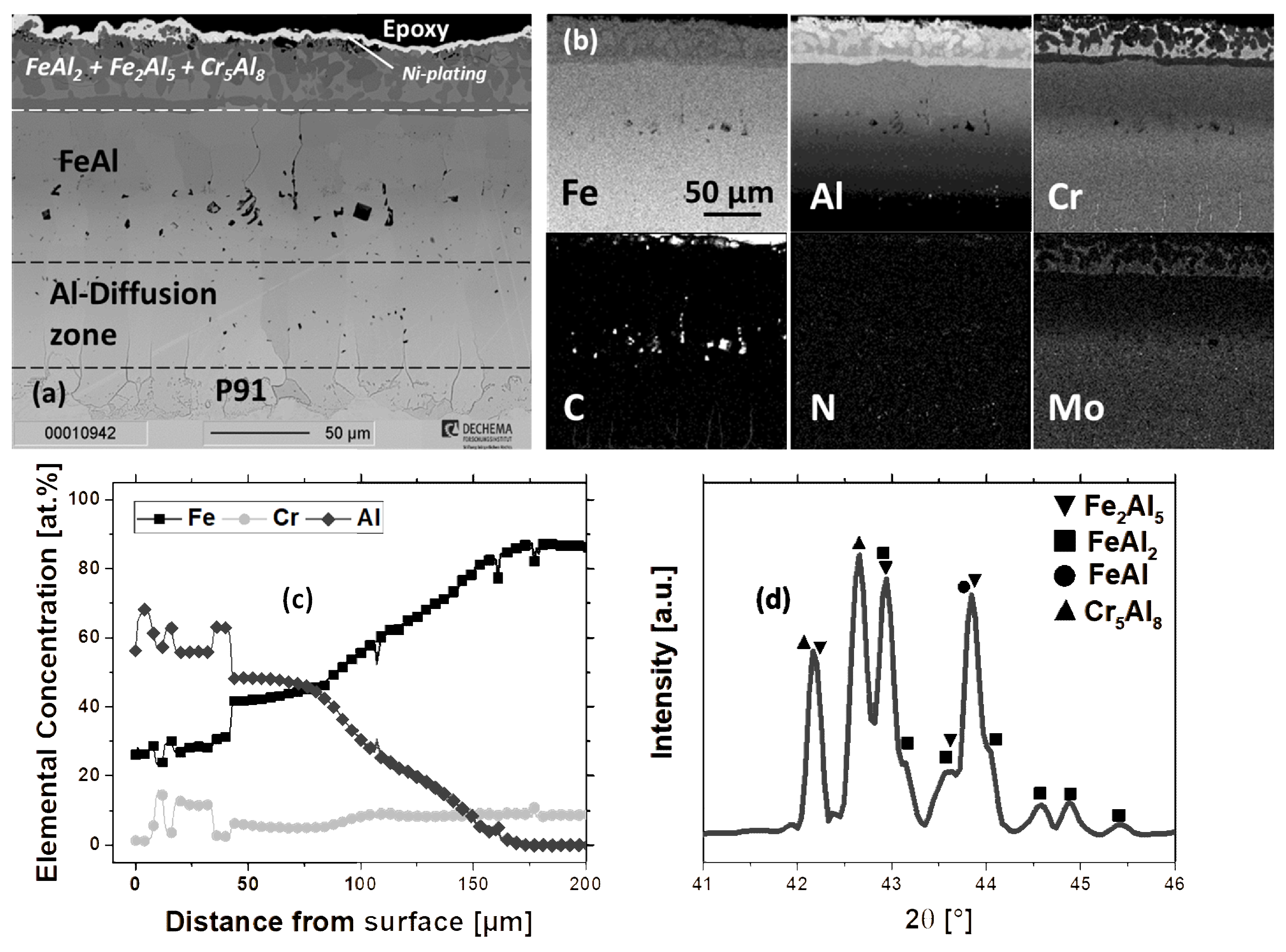
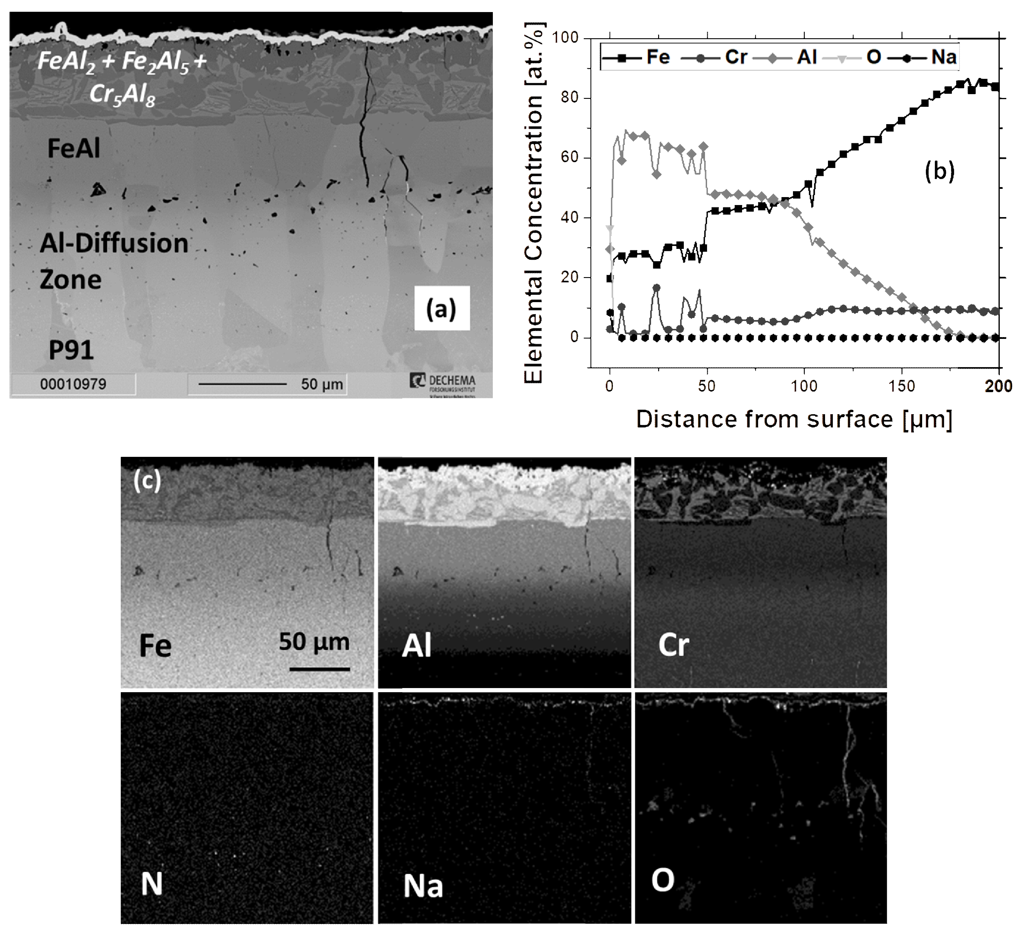
3.1.3. Cr/Al-Diffusion Coating

Figure 4 shows the cross-sectional BSE-image, elemental distribution maps, line scans of Fe, Cr and Al, and XRD-pattern of the Cr/Al-coating, which exhibited a similar microstructure and distinctive zones with differing chemical composition to the Al-coating (Figure 3). The Cr23C6 layer present in the as-chromized microstructure (see Figure 2) was dissolved during the aluminizing treatment. Al-diffusion into the former Cr-diffusion zone (Figure 2) led to the formation of an Al-rich (mean concentration of 60 at.%) outer layer with a larger thickness (ca. 40 µm) compared to the pure aluminide coating (see Figure 3; please note the different magnification). Similar to the aluminide coating, the outer layer of the Cr/Al-coating consisted of FeAl2 and Fe2Al5 phases, but also contained Cr-rich precipitates (see Cr map in Figure 4b), which were identified as the (Fe,Cr)5Al8 phase via XRD analysis (Figure 4d). The significant content of Fe determined in the Cr5Al8 phase (around 29 at.%) can be explained by the substitution of Cr by Fe in the Cr5Al8 phase, as reported by Palm [44]. Unlike Fe, the Cr-profile fluctuated strongly and its lower concentration (see Figure 4c) in the matrix agreed well with its reported maximum solubility of 4.1 at.% in FeAl2 and 6.5 at.% in Fe2Al5 [45]. Due to its limited solubility in these Al-rich Fe-Al phases, the excess Cr in the outer layer resulted in the formation of the Cr5Al8 precipitates, in which a significantly higher maximum Cr-concentration of 16 at.% was detected (see Figure 4c). Similar to chromium, the Mo-content increased up to 0.8 at.% (line scan not shown) within these precipitates (see Figure 4b). The enrichment of molybdenum in the Cr5Al8 precipitates derives from the refractory metal rich carbides at the grain boundaries as well as in the lower part of the Cr23C6 layer of the as-chromized microstructure (see Mo map in Figure 2b).
The inner layers of the Cr/Al-diffusion coating showed a strong Al-concentration gradient and a very similar microstructure to the Al-diffusion coating. Within the FeAl layer Kirkendall voids, fine nitride precipitates as well as cracks perpendicular to the surface were observed. The formation of cracks can again be explained by the build-up of tensile stresses during the cooling period of coating manufacturing due to the CTE mismatch between the coating phases and the substrate analogous to the aluminized specimen. Underneath the FeAl layer, an almost 60 µm thick Al-diffusion zone with finely dispersed Al nitride precipitates was formed.

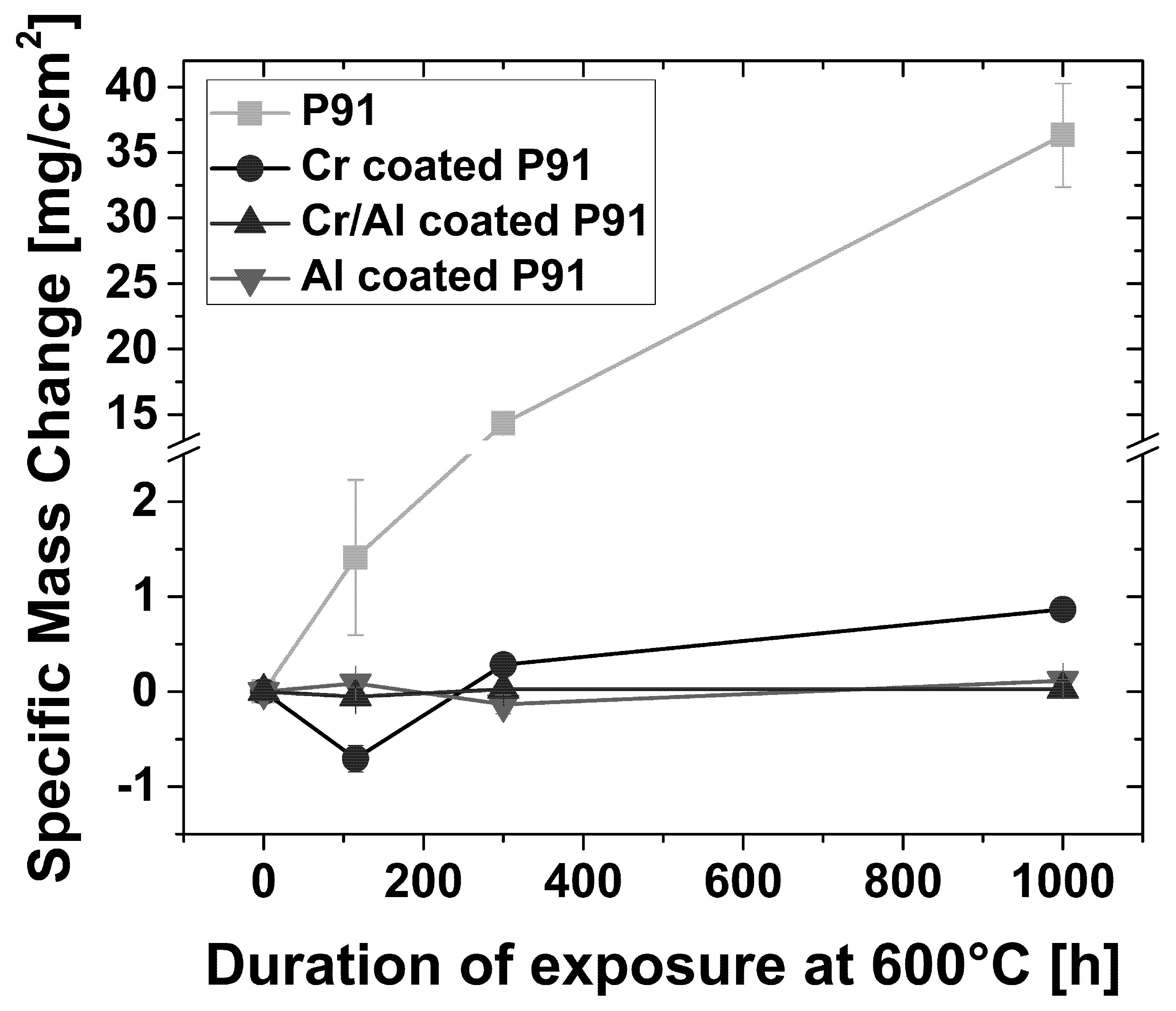
3.2. Exposure in Molten Solar Salt

The uncoated P91 specimen showed a markedly high specific net mass gain of 36.3 mg/cm2 after 1000 h of exposure at 600 °C in MSS (Figure 5). Similar very high mass gain values were reported in other studies in the literature [2,10,12] for P91 and other 9% Cr steels (such as P92) during isothermal exposure in molten nitrates at 600 °C. On the other hand, coated specimens exhibited a significantly lower mass gain. In particular, the Al- and Cr/Al-coated specimens both showed almost negligible mass gains, which can be interpreted as the formation of a highly protective oxide scale. However, it should be noted that spallation effects cannot be revealed solely based on net mass change kinetics. Hence, the mass change kinetics should be evaluated together with the findings of analytical characterization in order to verify the improvement of the scaling behavior via coatings with respect to the uncoated samples.
Post-exposure XRD analysis showed the formation of hematite, magnetite, and sodium ferrite (NaFeO2) on the uncoated P91 specimen after 1000 h exposure (Figure 6). Reflexes of NaNO3 and KNO3 were also detected, in addition to the corrosion products mentioned. This can be explained by the presence of salt residues, which apparently could not be removed from the sample surface upon rinsing in warm water and might possibly have also interfered with the determined value of specific mass change (Figure 5) to some extent. Nevertheless, taking into account the remarkably high specific mass change of the uncoated P91, this interference is considered to be very low. On the other hand, Cr2O3 was detected on the chromized P91 sample as well as hematite, magnetite, and sodium ferrite. XRD-patterns of Al- and Cr/Al-coated specimens exhibited the formation of corundum, hematite, and FeAl2O4 spinel as the oxide phases alongside the Fe-Al (as well as Cr5Al8 for the Cr/Al-coated sample) intermetallic phases, which were also present in the as-deposited coatings (see Figure 3 and Figure 4). Within the diffraction pattern of Al- and Cr/Al-coated samples, the reflex at the two theta value of nearly 33.5° could not be identified. Due to its close location to the reflexes of Fe2O3 (2θ = 33.2°) and Cr2O3 (2θ = 33.6°), this reflex could originate from a distorted corundum structure. Owing to its high intensity, this reflex can be associated with the alumina inclusions at the surface of the coating, resulting from the in-pack cementation process [30,46]. Compressive residual stresses lead to lattice distortion and could explain the shift of the reflex compared to the stress-free state [47,48].

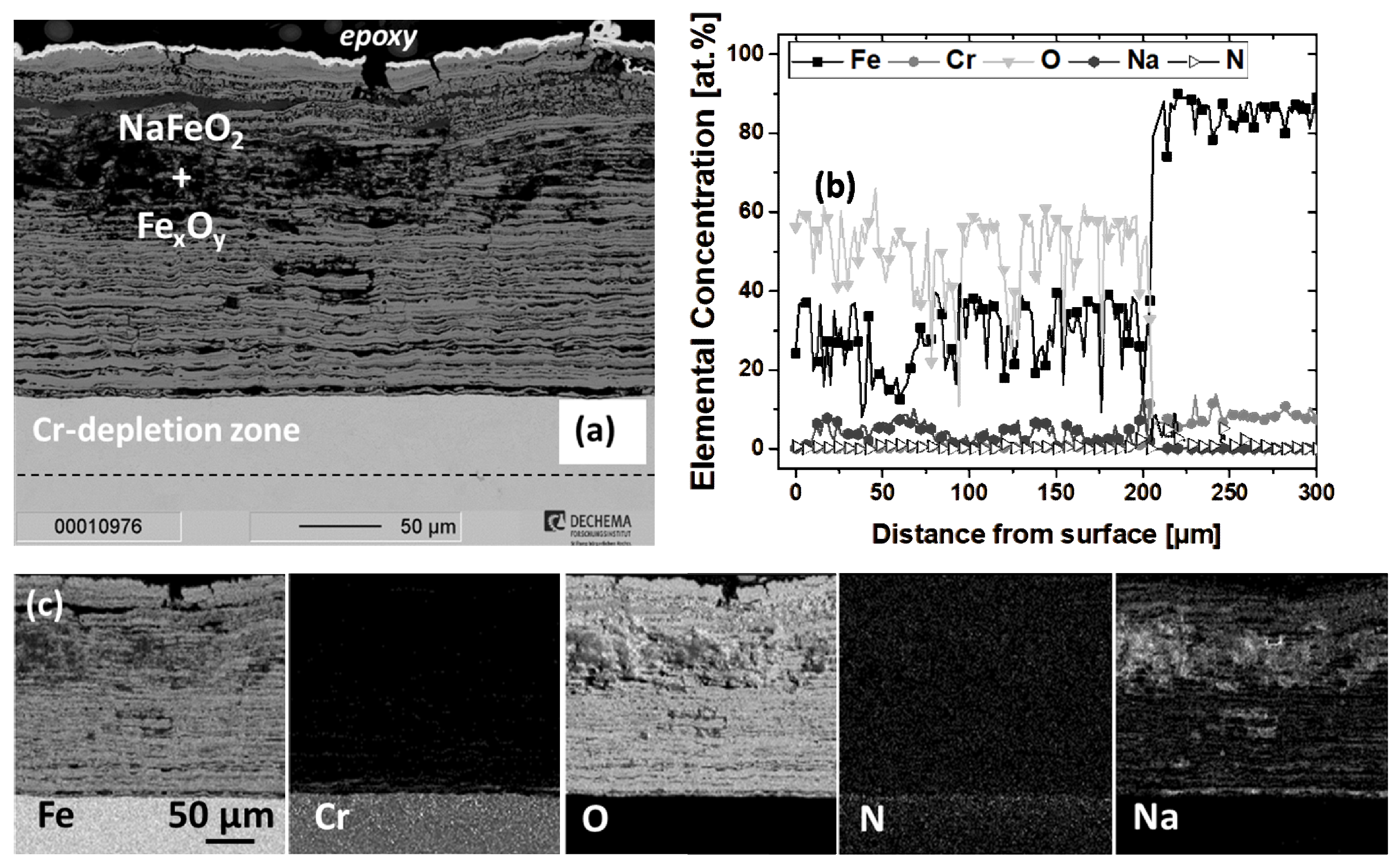
3.2.1. Scaling Behavior of Uncoated P91

An approximately 200 µm thick and porous oxide scale was formed on the uncoated P91 sample after 1000 h exposure in MSS at 600 °C, as shown in Figure 7. The oxide scale had a striated morphology and consisted of hematite, magnetite, and sodium ferrite, as identified by the post exposure XRD analysis (Figure 6). Interestingly, Cr was not present within the oxide scale, and underneath the oxide scale an approximately 40 µm thick Cr-depletion zone with a mean Cr-concentration of only 6 at.% was formed. This enhanced Cr-depletion from the alloy is explained by the transformation of Cr-rich oxide scales to chromate species and their dissolution into the salt melt [11,16]. With increasing exposure temperature, the decomposition of nitrate salts is accelerated, as highlighted in [1,8,14]. This leads to a higher equilibrium content of oxidizing agents in the salt melt, according to Reactions 1 and 2 and thereby enhanced Cr-depletion and thus an earlier onset of breakaway for P91 compared to lower exposure temperatures [26]. This is in good agreement with the study by Bradshaw and Carling, who reported an increasing extent of dissolved Cr cations in the salt melt with increasing temperature [8].
Instead of local enrichment at the scale/melt interface, Na was present within the whole oxide scale (see Na map in Figure 7c) up to a maximum concentration close to 10 at.% (Figure 7b). As aforementioned, NaFeO2 was detected via post-exposure XRD analysis (Figure 6). This is in good agreement with the study by Audigié et al. showing the formation of NaFeO2 in the multi-layered oxide scale grown on P91 during exposure in molten nitrates at 580 °C [25]. The incorporation of Na into the oxide scales and the consequential formation of sodium ferrite is attributed to the transfer of Na cations from the salt melt to the scale surface and their inward penetration through oxide scale defects such as pores and cracks [18]. Moreover, N was enriched underneath the porous oxide scale (see Figure 7b and N map in Figure 7c), suggesting the nitridation of the sub-scale region, which was also observed in other studies investigating the molten nitrate corrosion of this alloy at 580 °C [6,25]. Nitrogen transport through the oxide scale to the alloy surface can be associated with oxide scale defects.

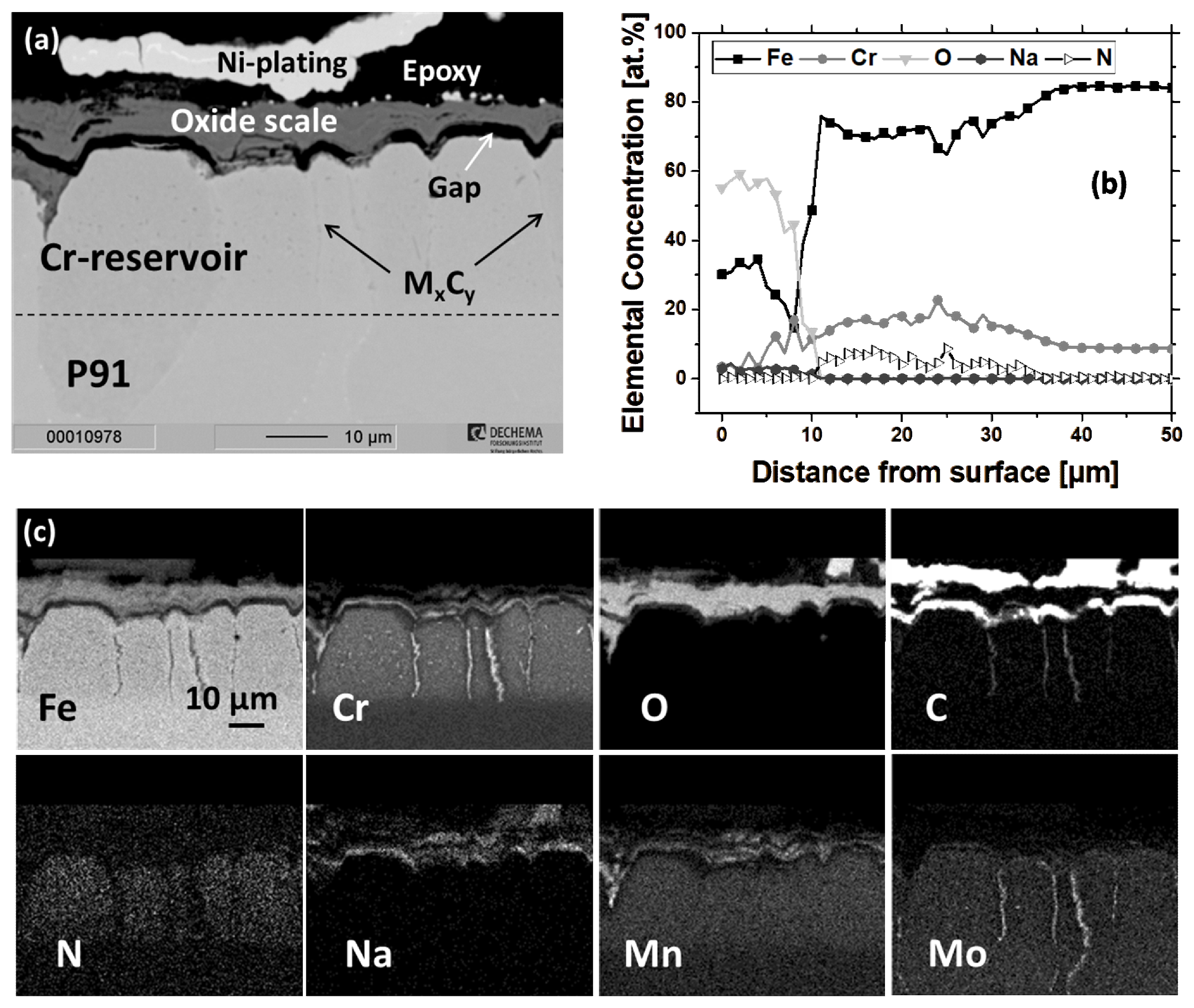
3.2.2. Scaling Behavior of Chromized P91

Figure 8 shows the cross-sectional BSE-image, elemental line scans, and distribution maps of the chromized P91 specimen after 1000 h exposure in MSS at 600 °C. In contrast to the 200 µm thick and highly non-protective oxide scale grown on the uncoated P91 specimen, the oxide scale grown on the chromized specimen was only 10 µm thick and consisted of an outer hematite and an inner Cr-rich oxide layer. The oxide scale formed at 600 °C in this study exhibited a very similar duplex morphology as the one grown on chromized P91 after exposure at 560 °C investigated in an earlier study [26]. Alongside the presence of hematite, Na was enriched within the outer layer of the oxide scale up to nearly 5 at.% (Figure 8b), which evidently led to the local formation of sodium ferrite, as identified by the XRD analysis (see Figure 6). In the study mentioned earlier, the Na-content in the oxide scale was significantly lower compared to this study and the formation of alkali ferrite species was excluded. Evidently, increased exposure temperature led to an enhanced Na inward flux from the melt to the scale, which can be associated with the increased basicity of the melt at higher temperatures, promoting the inward flux of Na cations [13]. At the scale/metal interface, a very thin and Cr-rich inner layer was formed. Post-exposure XRD analysis revealed the presence of Cr2O3 at the surface of the chromized specimen (Figure 6). The determined Cr-concentration of 17 at.% at the inner layer of the oxide scale (see Figure 8b) appeared to be low to stabilize Cr2O3. Evidently, the employed spatial resolution of 1 µm for EPMA line scans was not enough to clearly detect the Cr-concentration in the thin inner layer of the scale. Most likely, the EPMA signal was influenced by the surrounding regions, such as the gap at the interface between the oxide scale and the alloy surface, which was formed during metallographic preparation. Underneath the oxide scale, the as-deposited Cr23C6 layer (see Figure 2) was dissolved during exposure, but the Cr-diffusion zone with a mean Cr-concentration of 16 at.% was still visible after 1000 h exposure (Figure 8b). Notwithstanding, underneath the inner layer of the scale, Cr-depletion was observed to some extent, since the Cr-concentration dropped to 11.6 at.% at the surface of the coating (see Figure 8b). Nevertheless, the Cr-reservoir was evidently still adequate to counter-act the depletion of Cr to the salt, as was forecasted in an earlier study [26]. However, it should be mentioned that the oxide scale grown on the chromized P91 could not hinder the transfer of Na+ cations from the salt melt to the scale. While improving the scaling behavior substantially (see Figure 5), the application of the Cr-diffusion coating did not alter the aforementioned corrosion mechanisms that led to a breakaway of uncoated P91 (see Figure 7). Evidently, the transfer of Na cations from the melt to the scale and that of Cr cations in the counter direction were restrained, but not inhibited. Furthermore, N was enriched within the diffusion zone to a mean concentration of 5 at.% (Figure 8b), suggesting nitridation of the alloy sub-surface. Its enrichment was more pronounced in the ferrite grains rather than in the needle shaped Cr- and Mo-rich carbide precipitates at the grain boundaries (see Figure 8c).

3.2.3. Scaling Behavior of Al-Coated P91

The Al-coating formed an even thinner oxide scale compared to the chromized P91 specimen and did not show substantial microstructural alteration as shown in Figure 9. The enhanced stability of aluminized P91 is in good correlation with other studies in literature [12,25,26], which reported improved scaling behavior for slurry aluminized P91 in molten nitrate salts. Post-exposure XRD analysis revealed that the oxide scale grown on the aluminized specimen after 1000 h exposure in MSS at 600 °C consisted of corundum, hematite and FeAl2O4 (see Figure 6). Na was detected in the oxide scale to an extent of ca. 4 at.% (Figure 9b) as well as in the cracks (see Na map in Figure 9c), which healed during exposure.
EPMA line scans revealed the sustainment of the as-deposited Al-concentration under the surface (see Figure 3c and Figure 9b). Underneath the scale, the coating microstructure was almost identical to the as-deposited condition with an outer layer consisting of the Al-rich Fe-Al intermetallic phases (FeAl2 and Fe2Al5) above an intermediate FeAl layer and an inner Al-diffusion zone (see Figure 3a and Figure 9a). The cracks, which were present in the as-deposited condition, were healed during exposure, as can be best identified by the Al and O distribution maps in Figure 9c. Evidently, Kirkendall voids located at the interface between the FeAl layer and Al-diffusion zone in the as-deposited condition (see Figure 3a) did not grow during exposure (Figure 9a). Unlike its enrichment within the Cr-diffusion zone of the chromized specimen after 1000 h exposure (see Figure 8c), N was only detected in the nitride precipitates within the Al-diffusion zone (Figure 9c), which were also present in the as-deposited condition (see Figure 3b).

3.2.4. Scaling Behavior of Cr/Al-Coated P91

Cr/Al-coated P91 showed the lowest specific net mass gain (0.028 mg/cm2) after 1000 h exposure in MSS at 600 °C. Correspondingly, a very thin and adherent oxide scale was formed on the Cr/Al-coating, as shown in Figure 10. Similar to the Al-coating (see Figure 9), the microstructure of the Cr/Al-coating was barely altered after 1000 h exposure. Again, analogous to the Al-coating, the oxide scale grown on the Cr/Al-coating consisted of corundum, hematite, and FeAl2O4, as determined by XRD analysis (Figure 6). Furthermore, Na was detected within the oxide scale up to a concentration of 8 at.% (Figure 10b). The elemental distribution maps showed more homogeneous and pronounced Na enrichment within the oxide scale (see Na and O maps in Figure 10c) compared to the aluminized P91 (Figure 9). Underneath the oxide scale, the Al-reservoir of the as-deposited coating was maintained (see Figure 4c and Figure 10b) and hence, pristine coating phases, namely FeAl2, Fe2Al5 and Cr5Al8 in the outer layer and FeAl in the inner layer, were still present (Figure 6). Cracks perpendicular to the surface, which were present in the as-deposited condition (see Figure 4a), were filled with a Na- and Al-rich oxide (see Na, Al and O maps in Figure 10c). Similar to the aluminized P91, instead of being enriched in the diffusion zone during exposure, N was only detected within the nitride precipitates in the Al-diffusion zone (Figure 10c), which were present in the as-deposited condition (see Figure 4b).

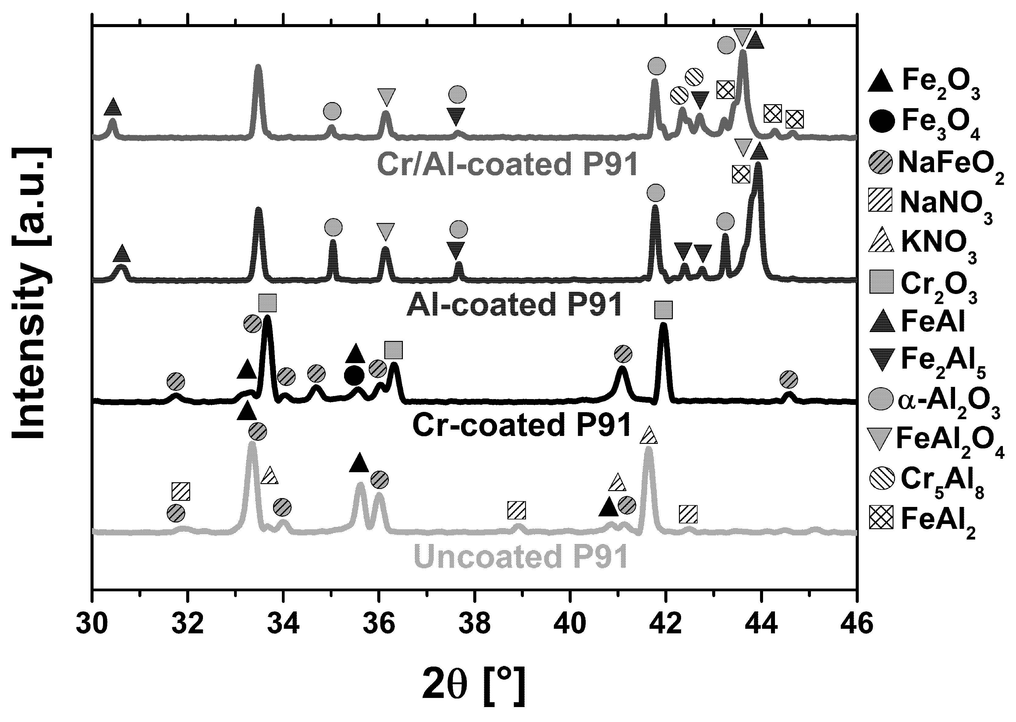
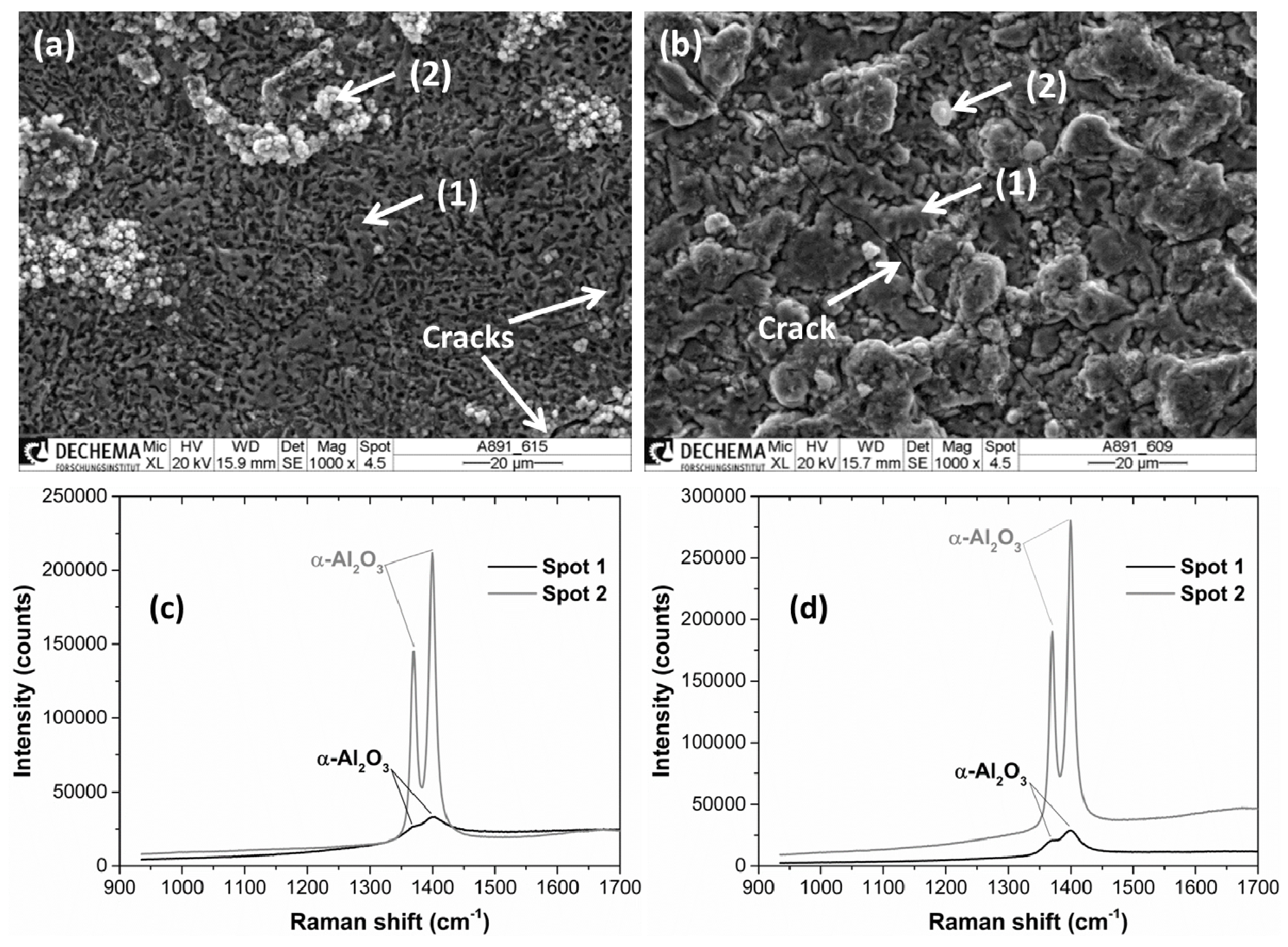
3.2.5. Formation of Corundum on Al- and Cr/Al-Coated P91

The presence of corundum on both investigated aluminide coatings after 1000 h exposure in MSS at 600 °C was confirmed by post-exposure XRD analysis (Figure 6). However, the characterization of thin oxide scales grown on coated specimens during molten salt exposure via XRD can be difficult. This limitation is based on the low intensity of reflexes from very thin scales, as well as the overlapping of reflexes belonging to several oxide and intermetallic phases, as highlighted in [12,24]. Raman spectroscopy was therefore used to ascertain the composition of the oxide scales grown on Al- and Cr/Al-coated specimens. Figure 11a shows the surface morphology of the scales formed on aluminized P91. A large fraction of the surface, appearing dark in the secondary electron image (representatively marked as spot 1), is covered with a very thin oxide scale (see Figure 9). The corresponding Raman spectrum (Figure 11c) exhibited the characteristic fluorescence doublet of α-Al2O3 at a frequency around 1400 cm−1 [49]. Local protrusions, appearing bright in the secondary electron image (representatively marked as spot 2), were also observed on the surface. Such protrusions were clearly composed of α-Al2O3 (see Figure 11c). The higher relative intensity of the α-Al2O3 fluorescence doublet on spot 2 compared to spot 1 can be explained by a larger fraction of oxide phase in the acquired volume of spot 2, since the scale in spot 1 is very thin (see Figure 9a). Similarly, Figure 11b exhibits the surface morphology of the scales formed on Cr/Al-coated P91 after 1000 h exposure in MSS at 600 °C. The surface is covered with α-Al2O3 as confirmed with the α-Al2O3 fluorescence doublet (spot 1 in Figure 11d). Compared to the aluminized P91, fewer protrusions were observed on the surface of the Cr/Al-coated P91 (Figure 11b). These protrusions were also smaller, suggesting that the re-healing of a protective α-Al2O3 scale was much faster for the Cr/Al-coated than the Al-coated P91.
To the authors’ knowledge, the formation of corundum during molten nitrate exposure has not been reported in the literature. Usually, exposure of Fe-Al binary alloys at temperatures below 1000 °C in air is associated with the initial formation of metastable Al2O3 phases such as γ and θ, followed by their transformation to the slow growing corundum [50]. The temperature dependence of the time required for the transformation of metastable alumina phases to α-Al2O3 would lead to the requirement of significantly long exposure durations for the formation of corundum at temperatures such as 600 °C. It should be noted, that compared to binary alloys, diffusion aluminide coatings have a strictly different chemical composition, which is strongly affected by the chemical composition of the substrate. Their distinctive chemical composition including alloying elements might lead to different behavior with respect to binary alloys. As a matter of fact, Cr can promote the formation and sustainment of a protective corundum scale on ferritic as well as austenitic steels with a low Al-content via the so-called “third element effect”, which is explained in detail elsewhere [51,52,53,54]. The sub-surface of the aluminide coating contained nearly 3 at.% Cr (see Figure 3c), whereas the Cr-content in the sub-surface of the Cr/Al-coating was substantially higher particularly due to the presence of Cr5Al8 precipitates (see Figure 4c). It could therefore be postulated, that the Cr-concentration at the sub-surface of both coatings might be sufficient to promote the formation and sustainment of a protective α-Al2O3 scale. In addition, despite the coating manufacturing process conducted in a reducing atmosphere (Ar + 5 vol.% H2), one could expect the formation of a native Al2O3 scale on the surface of Al-rich intermetallic phases (i.e., FeAl2, Fe2Al5 as well as Cr5Al8 for the Cr/Al-coating) considering the coating temperature around 1000 °C (see Table 2). The beneficial influence of the pre-oxidation of aluminide coatings upon aluminizing on the growth and sustainment of α-Al2O3 scales has been reported by Boulesteix et al. in steam exposure [49]. Furthermore, as aforementioned alumina particles can be incorporated into the coating due to the in-pack cementation process, as highlighted in [30]. The formation of a native Al2O3 scale along with the alumina inclusions from the pack cementation process might have acted as nucleation sites for the growth of corundum during exposure.
For both Al- and Cr/Al-coated P91, cracks can be observed through the oxide scales (Figure 11) and most likely correspond to areas adjacent to the vertical cracks observed in the cross-section images in Figure 9a and Figure 10a. These cracks were not associated with the spallation of the oxide scales, suggesting that the α-Al2O3 scales were strongly adherent to the underlying intermetallic coatings. The microstructure of both Al- and Cr/Al-coatings was not degraded during exposure in molten nitrates (see Figure 3 and Figure 4 for the as-deposited condition and Figure 9 and Figure 10 after exposure). This suggests that a very low extent of outward Al diffusion was sufficient to form a thin and adherent α-Al2O3 scale. Alumina, as a well-known insulator, can hinder the charge transfer between the specimen and the electrolyte. The observed protrusions (Figure 11) might have originated due to the local defects in the oxide scale and local increase in the electrochemical activity.
Notwithstanding the formation of corundum, it should be noted that Na-containing compounds such as NaAlO2 might have formed during the exposure, as highlighted in [16,24]. Tortorelli et al. conducted thermodynamic calculations and reported the stability of NaAlO2 for a wide p(O2)-p(N2) range at relevant temperatures for CSP operation [16]. These authors associated the high corrosion resistance of iron aluminides to the formation of a sodium aluminate scale and its low solubility in the salt melt. In this study, neither sodium aluminate nor any other Na-containing oxide phases were detected via post-exposure XRD analysis or Raman spectroscopy. This can be associated with the rinsing of the samples after exposure, galvanic Ni-plating, and subsequent metallographic preparation, which might have led to their dissolution, as highlighted in [16]. Hence the origin of Na enrichment in the oxide scale cannot definitely be linked to the formation of NaAlO2 with the employed analytical methods in this study. It should also be noted, that according to the binary Na2O-Al2O3 phase diagram [55], sodium has a solubility limit of nearly 3 at.% in corundum and increasing Na-concentration leads to the stabilization of β-Al2O3 (NaAl11O17) and NaAlO2 phases.
The possible formation of sodium aluminate can be associated with the basic dissolution of Al2O3 in a melt with high O2- activity such as molten nitrates, following the reactions (4) and (5):
Al 2 O 3 ( s ) + O 2 2 AlO 2
Na + + AlO 2 NaAlO 2 ( s )
The overall dissolution reaction can therefore be written as:
Al 2 O 3 ( s ) + Na 2 O 2 NaAlO 2 ( s )
The same mechanisms were proposed by Audigié et al. to explain the formation of sodium ferrite from hematite [25]. Despite no direct observation of sodium aluminate on Al- and Cr/Al-coated samples, the formation of a thin α-Al2O3 scale and possibly NaAlO2 on the surfaces were responsible for the superior corrosion resistance of the Al-rich coatings in MSS at 600 °C, as first proposed by Tortorelli et al. [16].

4. Conclusions

The scaling behavior of Cr-, Al- and Cr/Al-coatings deposited on P91 in MSS at 600 °C was studied with respect to uncoated P91. The investigated diffusion coatings significantly increased the corrosion resistance of P91 in the above-mentioned CSP relevant exposure conditions. Hence, diffusion coatings can enable the employment of ferritic-martensitic steels as structural materials in CSP systems with TES, which can increase the cost-efficiency due to their lower unit price compared to austenitic steels and Ni-based alloys. The additional costs associated with the coating processes e.g., pack cementation are economically viable considering the notable increase in lifetime of ferritic-martensitic steels in MSS via coatings.
The oxide scale grown on uncoated P91 exposed in MSS at 600 °C for 1000 h was nearly 200 µm thick and exhibited a porous and striated morphology which consisted of hematite, magnetite, and sodium ferrite. Na was detected over the whole thickness of the oxide scale to a concentration close to 10 at.%. Notably, Cr was completely depleted from the oxide scale, suggesting the formation of chromate species and their dissolution in the salt melt. In contrast, the oxide scale grown on the chromized specimen was only 10 µm thick and possessed a Cr-rich inner layer alongside the outer hematite layer. Compared to the uncoated P91, sodium ferrite was detected to a lesser extent at the surface of the chromized specimen. The incorporation of Na into the oxide scale suggested that similar corrosion mechanisms prevailed for both uncoated and chromized P91 specimens. However, despite nitridation of the sub-surface to some extent, the Cr-reservoir was maintained and thus breakaway of P91 in MSS was shifted to prolonged exposure durations via the Cr-diffusion coating.
Al- and Cr/Al-coatings exhibited an almost unaltered microstructure due to the very low extent of interdiffusion at the exposure temperature, as well as an evidently very low extent of outward Al diffusion being sufficient to form a highly protective oxide scale. The scale morphology was more homogeneous in the case of the Cr/Al-coating, which was associated with the presence of Cr5Al8 precipitates increasing the Al-activity at the sub-surface enabling faster healing of the oxide scale as well as promoting corundum formation via the third element effect. Raman spectroscopy verified the formation of corundum on both coatings at the relatively low exposure temperature. The highly protective behavior of aluminide coatings was associated with corundum being an electrical insulator and thus hindering charge transfer between the electrolyte and sample surface. However, it should be noted that the formation of NaAlO2 alongside corundum cannot be excluded, since the metallographic preparation of the samples might have led to its dissolution. Nevertheless, due to its low solubility in the salt melt, the possible formation of sodium aluminate on the aluminide coated specimens should not deteriorate the protective behavior, which is expected to be sustained for prolonged exposure durations.

5. Outlook

The formation of hexavalent Cr cations during exposure in molten nitrate salts should be considered as an important environmental issue due to chromates being highly toxic, especially considering the amount of salt utilized in CSP plants. Therefore, the determination of metal cations including Cr6+ and the investigation of nitrite content in the solar salt during exposure of coated as well as uncoated alloys is to be studied in future. Moreover, the corrosion behavior of alumina forming stainless steels at the studied temperature range is considered to be interesting for CSP applications, similar to the investigation at a lower temperature of 390 °C in [56]. Furthermore, the influence of diffusion coatings on the mechanical behavior of P91 should be of future interest to elucidate its employment in CSP plants. The formation of a large ferritic zone due to the inward diffusion of ferrite formers e.g., Al, refractory carbide precipitates in the as-chromized microstructure as well as cracks in the as-deposited condition of aluminide coatings are expected to influence the mechanical behavior of P91, which will be investigated in a future study.

Author Contributions

Conceptualization, C.O., T.M.M. and M.C.G.; Methodology, C.O., T.M.M., C.D. and B.G.; Investigation, C.O., T.M.M., C.D. and B.G.; Data Curation, C.O., T.M.M., C.D. and B.G.; Writing–Original Draft Preparation, C.O., T.M.M. and B.G.; Writing–Review and Editing, C.O., T.M.M., B.G. and M.C.G.

Funding

This research has received funding from the European Union’s Horizon 2020 research and innovation program under grant agreement No. 686008 (RAISELIFE).

Acknowledgments

The authors would like to acknowledge Gerald Schmidt for the EPMA measurements, Nadine Thuma for the metallographic preparation, and Rick N. Durham for proofreading. Furthermore, the authors would like to thank all project partners from the “RAISELIFE” project for helpful scientific discussions.

Conflicts of Interest

The authors declare no conflict of interest.

References

  1. Bonk, A.; Sau, S.; Uranga, N.; Hernaiz, M.; Bauer, T. Advanced heat transfer fluids for direct molten salt line-focusing CSP plants. Prog. Energy Combust. Sci. 2018, 67, 69–87. [Google Scholar] [CrossRef]
  2. Soleimani-Dorcheh, A.; Durham, R.N.; Galetz, M.C. Corrosion behavior of stainless and low-chromium steels and IN625 in molten nitrate salts at 600 C. Sol. Energy Mater. Sol. Cells 2016, 144, 109–116. [Google Scholar] [CrossRef]
  3. Barlev, D.; Vidu, R.; Stroeve, P. Innovation in concentrated solar power. Sol. Energy Mater. Sol. Cells 2011, 95, 2703–2725. [Google Scholar] [CrossRef]
  4. Vignarooban, K.; Xu, X.; Arvay, A.; Hsu, K.; Kannan, A.M. Heat transfer fluids for concentrating solar power systems—A review. Appl. Energy 2015, 146, 383–396. [Google Scholar] [CrossRef]
  5. Boretti, A.; Casteletto, S.; Al-Zubaidy, S. Concentrating solar power tower technology: Present status and outlook. Nonlinear Eng. 2019, 8, 10–31. [Google Scholar] [CrossRef]
  6. Agüero, A.; Audigié, P.; Rodríguez, S.; Encinas-Sánchez, V.; de Miguel, M.T.; Pérez, F.J. Protective coatings for high temperature molten salt heat storage systems in solar concentration power plants. In AIP Conference Proceedings; AIP Publishing: Melville, NY, USA, 2018; Volume 2033. [Google Scholar]
  7. Bonk, A.; Braun, M.; Hanke, A.; Forstner, J.; Rückle, D.; Kaesche, S.; Sötz, V.A.; Bauer, T. Influence of different atmospheres on molten salt chemistry and its effect on steel corrosion. In AIP Conference Proceedings; AIP Publishing: Melville, NY, USA, 2018; Volume 2033. [Google Scholar]
  8. Bradshaw, R.W.; Carling, R.W. A review of the chemical and physical properties of molten alkali nitrate salts and their effect on materials used for solar central receivers. Proc. Electrochem. Soc. 1987, 1987, 959–969. [Google Scholar] [CrossRef]
  9. Kruizenga, A.; Gill, D. Corrosion of iron stainless steels in molten nitrate salt. Energy Procedia 2014, 49, 878–887. [Google Scholar] [CrossRef]
  10. Spiegel, M.; Mentz, J. High temperature corrosion beneath nitrate melts. Mater. Corros. 2014, 65, 276–281. [Google Scholar] [CrossRef]
  11. Summers, K.L.; Chidambaram, D. Corrosion behavior of structural materials for potential use in nitrate salts based solar thermal power plants. J. Electrochem. Soc. 2017, 164, 5357–5363. [Google Scholar] [CrossRef]
  12. Soleimani-Dorcheh, A.; Galetz, M.C. Slurry aluminizing: A solution for molten nitrate salt corrosion in concentrated solar power plants. Sol. Energy Mater. Sol. Cells 2016, 146, 8–15. [Google Scholar] [CrossRef]
  13. Fernandez, A.G.; Lasanta, M.I.; Perez, F.J. Molten salt corrosion of stainless steels and low-Cr steel in CSP plants. Oxid. Met. 2012, 78, 329–348. [Google Scholar] [CrossRef]
  14. McConohy, G.; Kruizenga, A. Molten nitrate salts at 600 and 680 C: Thermophysical property changes and corrosion of high-temperature nickel alloys. Sol. Energy 2014, 103, 242–252. [Google Scholar] [CrossRef]
  15. Rapp, R.A.; Goto, K.S. The hot corrosion of metals by molten salts. In Proceedings of the Second International Symposium on Molten Salts; Selman, R., Braunstein, J., Eds.; Electrochemical Society: Pennington, NJ, USA, 1981; pp. 159–177. [Google Scholar]
  16. Tortorelli, P.F.; Bishop, P.S.; DiStefano, J.R. Selection of Corrosion-Resistant Materials for Use in Molten Nitrate Salts ORNL/TM-11162; Oak Ridge National Lab.: Oak Ridge, TN, USA, 1989.
  17. Bradshaw, R.W.; Clift, W.M. Effect of Chloride Content of Molten Nitrate Salt on Corrosion of A516 Carbon Steel; Sandia Report, SAND2010-7594; Sandia National Laboratories: Albuquerque, NM, USA; Livermore, CA, USA, 2010.
  18. Dorcheh, A.S.; Durham, R.N.; Galetz, M.C. High temperature corrosion in molten solar salt: The role of chloride impurities. Mater. Corros. 2017, 68, 943–951. [Google Scholar] [CrossRef]
  19. Encinas-Sánchez, V.; de Miguel, M.T.; Lasanta, M.I.; García-Martín, G.; Pérez, F.J. Electrochemical impedance spectroscopy (EIS): An efficient technique for monitoring corrosion processes in molten salt environments in CSP applications. Sol. Energy Mater. Sol. Cells 2019, 191, 157–163. [Google Scholar] [CrossRef]
  20. Bradshaw, R.W.; Goods, S.H. Corrosion Resistance of Stainless Steels During Thermal Cycling in Alkali Nitrate Molten Salts; Sandia Report, SAND2001-8518; Sandia National Laboratories: Albuquerque, NM, USA; Livermore, CA, USA, 2001.
  21. Goods, S.H.; Bradshaw, R.W. Corrosion of stainless steels and carbon steel by molten mixtures of commercial nitrate salts. J. Mater. Eng. Perform. 2004, 13, 78–87. [Google Scholar] [CrossRef]
  22. Slusser, J.W.; Titcomb, J.B.; Heffelfinger, M.T.; Dunbobbin, B.R. Corrosion in molten nitrate-nitrite salts. JOM 1985, 37, 24–27. [Google Scholar] [CrossRef]
  23. Fähsing, D. Ferritisch Martensitische Stähle: Verbesserung der Oxidationsbeständigkeit in Wasserdampfhaltigen Hochtemperaturatmosphären. Ph.D. Thesis, RWTH Aachen, Shaker Verlag, Herzogenrath, Germany, 2015. [Google Scholar]
  24. Audigié, P.; Bizien, N.; Baráibar, I.; Rodriguez, S.; Pastor, A.; Hernández, M.; Agüero, A. Aluminide slurry coatings for protection of ferritic steel in molten nitrate corrosion for concentrated solar power technology. In AIP Conference Proceedings; AIP Publishing: Melville, NY, USA, 2017; Volume 1850, p. 070002. [Google Scholar]
  25. Audigié, P.; Encinas-Sánchez, V.; Juez-Lorenzo, M.; Rodríguez, S.; Gutiérrez, M.; Pérez, F.J.; Agüero, A. High temperature molten salt corrosion behavior of aluminide and nickel-aluminide coatings for heat storage in concentrated solar power plants. Surf. Coat. Technol. 2018, 349, 1148–1157. [Google Scholar] [CrossRef]
  26. Fähsing, D.; Oskay, C.; Meißner, T.M.; Galetz, M.C. Corrosion testing of diffusion-coated steel in molten salt for concentrated solar power tower systems. Surf. Coat. Technol. 2018, 354, 46–55. [Google Scholar] [CrossRef]
  27. Material Data Sheet P91/T91; Thyssen Krupp Materials International: Essen, Germany, 2011.
  28. Goward, G.W. Protective Coatings for High Temperature Alloys: State of Technology. In Proceedings of the Symposium on Properties of High-Temperature Alloys with Emphasis on Environmental Effects, New York, NY, USA, 17 October 1976. [Google Scholar]
  29. Duret, C.; Pichoir, R. Protective Coatings for High Temperature Materials: Chemical Vapour Deposition and Pack Cementation Processes. In Coatings for High Temperature Applications; Lang, E., Ed.; Applied Science Publishers: London, UK, 1983; pp. 33–78. [Google Scholar]
  30. Mevrel, R.; Duret, C.; Pichoir, R. Pack cementation processes. Mater. Sci. Technol. 1986, 2, 201–206. [Google Scholar] [CrossRef]
  31. Rohr, V.; Donchev, A.; Schütze, M.; Milewska, A.; Pérez, F.J. Diffusion coatings for high temperature corrosion protection of 9–12% Cr steels. Corros. Eng. Sci. Technol. 2005, 40, 226–232. [Google Scholar] [CrossRef]
  32. ISO 17245:2015 Corrosion of Metals and Alloys—Test Method for High Temperature Corrosion Testing of Metallic Materials by Immersing in Molten Salt or Other Liquids under Static Conditions; ISO: Geneva, Switzerland, 2015.
  33. Schmidt, D.; Galetz, M.C.; Schütze, M. Ferritic–martensitic steels: Improvement of the oxidation behavior in steam environments via diffusion coatings. Surf. Coat. Technol. 2013, 237, 23–29. [Google Scholar] [CrossRef]
  34. Bianco, R.; Rapp, R.A. Pack cementation diffusion coatings. In Metallurgical and Ceramic Protective Coatings; Stern, K.H., Ed.; Chapman & Hall: London, UK, 1996; pp. 236–260. [Google Scholar]
  35. Meier, G.H.; Cheng, C.; Perkins, R.A.; Bakker, W. Diffusion chromizing of ferrous alloys. Surf. Coat. Technol. 1989, 39, 53–64. [Google Scholar] [CrossRef]
  36. Agüero, A.; Muelas, R.; Pastor, A.; Osgerby, S. Long exposure steam oxidation testing and mechanical properties of slurry aluminide coatings for steam turbine components. Surf. Coat. Technol. 2005, 200, 1219–1224. [Google Scholar] [CrossRef]
  37. Bates, B.L.; Zhang, Y.; Dryepondt, S.; Pint, B.A. Creep behavior of pack cementation aluminide coatings on grade 91 ferritic–martensitic alloy. Surf. Coat. Technol. 2014, 240, 32–39. [Google Scholar] [CrossRef]
  38. Rohr, V.; Schütze, M.; Fortuna, E.; Tsipas, D.N.; Milewska, A.; Pérez, F.J. Development of novel diffusion coatings for 9–12% Cr ferritic-martensitic steels. Mater. Corros. 2005, 56, 874–881. [Google Scholar] [CrossRef]
  39. Zhang, Y.; Pint, B.A.; Cooley, K.M.; Haynes, J.A. Formation of aluminide coatings on Fe-based alloys by chemical vapor deposition. Surf. Coat. Technol. 2008, 202, 3839–3849. [Google Scholar] [CrossRef]
  40. Naji, A.; Galetz, M.C.; Schütze, M. Improvements in the thermodynamic and kinetic considerations on the coating design for diffusion coatings formed via pack cementation. Mater. Corros. 2015, 66, 863–868. [Google Scholar] [CrossRef]
  41. Touloukian, Y.S.; Kirby, R.K.; Taylor, R.E.; Desai, P.D. Thermal Expansion of Metallic Elements and Alloy; Plenum Publishing Corporation: New York, NY, USA, 1970. [Google Scholar]
  42. Fähsing, D.; Rudolphi, M.; Konrad, L.; Galetz, M.C. Fireside Corrosion of Chromium-and Aluminum-Coated Ferritic–Martensitic Steels. Oxid. Met. 2017, 88, 155–164. [Google Scholar] [CrossRef]
  43. Zhang, Y.; Pint, B.A.; Cooley, K.M.; Haynes, J.A. Effect of nitrogen on the formation and oxidation behavior of iron aluminide coatings. Surf. Coat. Technol. 2005, 200, 1231–1235. [Google Scholar] [CrossRef]
  44. Palm, M. The Al–Cr–Fe system–Phases and phase equilibria in the Al-rich corner. J. Alloy Compd. 1997, 252, 192–200. [Google Scholar] [CrossRef]
  45. Pavlyuchkov, D.; Przepiórzynski, B.; Kowalski, W.; Velikanova, T.Y.; Grushko, B. Al–Cr–Fe phase diagram. Isothermal Sections in the region above 50 at% Al. Calphad 2014, 45, 194–203. [Google Scholar] [CrossRef]
  46. Das, D.K.; Singh, V.; Joshi, S.V. Evolution of aluminide coating microstructure on nickel-base cast superalloy CM-247 in a single-step high-activity aluminizing process. Metall. Mater. Trans. A 1998, 29, 2173–2188. [Google Scholar] [CrossRef]
  47. Fitzpatrick, M.E.; Fry, A.T.; Holdway, P.; Kandil, F.A.; Shackleton, J.; Suominen, L. Determination of Residual Stresses by X-ray Diffraction Measurement Good Practice Guide 52; National Physical Laboratory: Teddington, Middlesex, UK, 2005. [Google Scholar]
  48. Kamminga, J.D.; de Keijser, T.H.; Mittemeijer, E.J.; Delhez, R. New methods for diffraction stress measurement: A critical evaluation of new and existing methods. J. Appl. Cryst. 2000, 33, 1059–1066. [Google Scholar] [CrossRef]
  49. Boulesteix, C.; Kolarik, V.; Pedraza, F. Steam oxidation of aluminide coatings under high pressure and for long exposures. Corros. Sci. 2018, 144, 328–338. [Google Scholar] [CrossRef] [Green Version]
  50. Grabke, H.J. Oxidation of NiAl and FeAl. Intermetallics 1999, 7, 1153–1158. [Google Scholar] [CrossRef]
  51. Stott, F.H.; Wood, G.C.; Stringer, J. The influence of alloying elements on the development and maintenance of protective scales. Oxid. Met. 1995, 44, 113–145. [Google Scholar] [CrossRef]
  52. Brady, M.P.; Yamamoto, Y.; Santella, M.L.; Walker, L.R. Composition, microstructure, and water vapor effects on internal/external oxidation of alumina-forming austenitic stainless steels. Oxid. Met. 2009, 72, 311–333. [Google Scholar] [CrossRef]
  53. Heinonen, M.H.; Kokko, K.; Punkkinen, M.P.J.; Nurmi, E.; Kollár, J.; Vitos, L. Initial oxidation of Fe–Al and Fe–Cr–Al alloys: Cr as an alumina booster. Oxid. Met. 2011, 76, 331–346. [Google Scholar] [CrossRef]
  54. Renusch, D.; Grimsditch, M.; Koshelev, I.; Veal, B.W. Strain Determination in Thermally-Grown Alumina Scales Using Fluorescence Spectroscopy. Oxid. Met. 1997, 48, 471–795. [Google Scholar] [CrossRef]
  55. Lambotte, G.; Chartrand, P. Thermodynamic modeling of the (Al2O3 + Na2O), (Al2O3 + Na2O + SiO2), and (Al2O3 + Na2O + AlF3 + NaF) systems. J. Chem. Thermodyn. 2013, 57, 306–334. [Google Scholar] [CrossRef]
  56. Fernandez, A.G.; Rey, A.; Lasanta, I.; Mato, S.; Brady, M.P.; Perez, F.J. Corrosion of alumina-forming austenitic steel in molten nitrate salts by gravimetric analysis and impedance spectroscopy. Mater. Corros. 2014, 65, 267–275. [Google Scholar] [CrossRef]
Figure 1. Schematic illustration of the corrosion test rig for exposure in molten solar salt at 600 °C.
Coatings 09 00687 g001
Figure 2. (a) Cross-sectional back scattered electron (BSE) image, (b) elemental distribution maps and (c) quantitative line scans of Fe, Cr and C as well as (d) X-ray diffraction (XRD) pattern of Cr-diffusion coated P91. Please note the low adherence of the Ni-plating, resulting in the incorporation of the epoxy into the surface of the coating during mounting.
Coatings 09 00687 g002
Figure 3. (a) Cross-sectional BSE-image, (b) elemental distribution maps and (c) quantitative line scans of Fe, Cr and Al as well as (d) XRD-pattern of aluminized P91.
Coatings 09 00687 g003
Figure 4. (a) Cross-sectional BSE-image, (b) elemental distribution maps and (c) quantitative line scans of Fe, Cr, and Al, as well as (d) XRD-pattern of Cr/Al-diffusion coated P91.
Coatings 09 00687 g004
Figure 5. Specific mass change during isothermal exposure in molten solar salt at 600 °C. Please note the y-axis break.
Coatings 09 00687 g005
Figure 6. XRD patterns of uncoated, chromized, Al- and Cr/Al-coated P91 specimens after 1000 h exposure in molten solar salt at 600 °C.
Coatings 09 00687 g006
Figure 7. (a) Cross-sectional BSE-image, (b) quantitative line scans of Fe, Cr, O, Na, and N, and (c) elemental distribution maps of uncoated P91 after 1000 h isothermal exposure in molten solar salt at 600 °C.
Coatings 09 00687 g007
Figure 8. (a) Cross-sectional BSE-image, (b) quantitative line scans of Fe, Cr, O, Na, and N, and (c) elemental distribution maps of chromized P91 after 1000 h isothermal exposure in molten solar salt at 600 °C.
Coatings 09 00687 g008
Figure 9. (a) Cross-sectional BSE-image, (b) quantitative line scans of Fe, Cr, Al, O and Na and (c) elemental distribution maps of aluminized P91 after 1000 h isothermal exposure in molten solar salt at 600 °C.
Coatings 09 00687 g009
Figure 10. (a) Cross-sectional BSE-image, (b) quantitative line scans of Fe, Cr, Al, O, and Na, and (c) elemental distribution maps of Cr/Al-coated P91 after 1000 h isothermal exposure in molten solar salt at 600 °C.
Coatings 09 00687 g010
Figure 11. Oxidized surface morphologies and Raman spectra (fluorescence) from the marked spots of (a,c) aluminized and (b,d) Cr/Al-coated P91 after 1000 h isothermal exposure in molten solar salt at 600 °C.
Coatings 09 00687 g011
Table 1. Nominal composition (in wt.%) of the ferritic-martensitic steel, P91, used in this study [27].
AlloyFeCCrNiMnSiPSMoVAlNbN
P91bal.0.08–
0.12
8–
9.5
≤0.40.3–
0.6
0.2–
0.5
≤0.02≤0.010.85–
1.05
0.18–
0.25
≤0.040.06–
0.1
0.03–
0.07
Table 2. Overview of the manufacturing parameters for Cr- and Al-coatings as well as the Cr/Al-coating for which both single-step processes were carried out successively.
Diffusion ElementPowder CompositionProcess Parameters
Master AlloyActivatorInert FillerTemperatureTimeAtmosphere
CrCrMnCl2Al2O31050 °C2 hAr + 5% H2
AlAlNH4ClAl2O31000 °C1 hAr + 5% H2

