Article

Fatigue and Mechanical Behavior of Ti-6Al-4V Alloy with CrN and TiN Coating Deposited by Magnetic Filtered Cathodic Vacuum Arc Process

1
State Key Laboratory for Mechanical Behavior of Materials, School of Materials Science and Engineering, Xi’an Jiaotong University, Xi’an 710049, China
2
State Key Laboratory for Manufacturing Systems Engineering, Xi’an Jiaotong University, Xi’an 710049, China
3
Science and Technology on Plasma Dynamics Laboratory, Air Force Engineering University, Xi’an 710038, China
*
Author to whom correspondence should be addressed.
Coatings 2019, 9(10), 689; https://doi.org/10.3390/coatings9100689
Submission received: 5 October 2019 / Revised: 20 October 2019 / Accepted: 21 October 2019 / Published: 22 October 2019
(This article belongs to the Section Surface Characterization, Deposition and Modification)

Abstract

:
Coatings of 3 μm CrN and TiN were prepared by a magnetic filtered cathodic vacuum arc process (MFCVA) on Ti-6Al-4V substrates, respectively. Rotating bending tests and uniaxial tests were conducted for investigating the effect of the thin and uniformly distributed hard CrN and TiN coatings on the fatigue and mechanical properties of Ti-6Al-4V substrate. During both tests, no coating spallation phenomenon was observed, which indicated that the hard coating bound well with the substrate. The fatigue test results showed that the fatigue strength of the coated sample was decreased in both the low- and high-cycling fatigue regimes compared with the uncoated Ti-6Al-4V substrate. Compared with the TiN coating, the CrN coating caused a more significant reduction on the fatigue property of the uncoated Ti-6Al-4V substrate due to its inferior plastic deformation capacity. Furthermore, the tensile test results showed that the coated sample had a relative higher ultimate strength, yield strength, and lower elongation compared with the uncoated Ti-6Al-4V substrate. This may be due to the fact that the hard coating could suppress the initiation of cracks, and so higher stress was needed for crack initiating. During the crack propagation period, the hard coating cracked at a relative higher velocity, which led to cracking of the ductile substrate and elongation reduction.

1. Introduction

Ti-6Al-4V alloy has been extensively used in aviation and aerospace industries because of its high specific strength, light weight, and corrosion resistance [1,2,3]. However, its poor tribological behavior, low wear, and anti-erosion resistance have limited the extension of Ti-6Al-4V [4,5]. Transition metal nitrides and other types of hard coating or film are convenient and effective surface strengthening techniques for expanding the application of Ti-6Al-4V. Among those transition metal nitrides-based coatings, CrN and TiN hard coating are two important coatings, as plenty of related studies have reported [6,7,8,9,10]. However, with the introduction of heterogenous hard brittle coating, the mechanical and fatigue property of Ti-6Al-4V substrate will be inevitably affected [6,11]. Furthermore, according to the service conditions of aerospace parts, aircraft engine compressor blades or other components are subjected to low-cycle fatigue, high-cycle fatigue, and other types of loads [12,13]. This means that the fatigue behavior as well as mechanical strength of the coated titanium alloy parts should not be significantly weakened.
During recent years, the effects of transition metal nitride hard coatings on fatigue properties have attracted researcher’s attention. Costa et al. studied the effect of CrN and TiN coatings on the Ti-6Al-4V substrate by axial fatigue test and pointed out that these two hard coatings decreased the fatigue limit of Ti-6Al-4V [14]. Bai et al. reported the similar phenomenon that the fatigue limit of Ti-6Al-4V alloy could be significantly reduced by brittle CrAlN coating through tension-tension fatigue tests [15]. Midori et al. also pointed out that TiN coating on Ti alloy decreased fatigue of the substrate due to the defects in the coating which were regarded as fatigue crack initiation sites [16]. Lee et al. reported that, through four-point fatigue test, TiN coating can improve the fatigue behavior of Ti-6Al-4V [17]. However, few studies concerned the fatigue behavior of Ti-6Al-4V alloy with CrN and TiN hard coating under rotating bending conditions and mechanical behavior under uniaxial tensile conditions have been reported.
In this paper, CrN and TiN hard coatings with approximately the same thickness and uniformly distributed on dog-bone shaped specimens were fabricated using a magnetic filtered cathodic vacuum arc method (MFCVA) on Ti-6Al-4V alloy. The surface condition, structure and mechanical property of the prepared coatings were examined. The influence of the hard coatings on the fatigue properties was investigated by a rotating bending fatigue test. Special attention was paid on the effect of hard coating on the mechanical behavior of Ti-6Al-4V alloy.

2. Materials and Methods

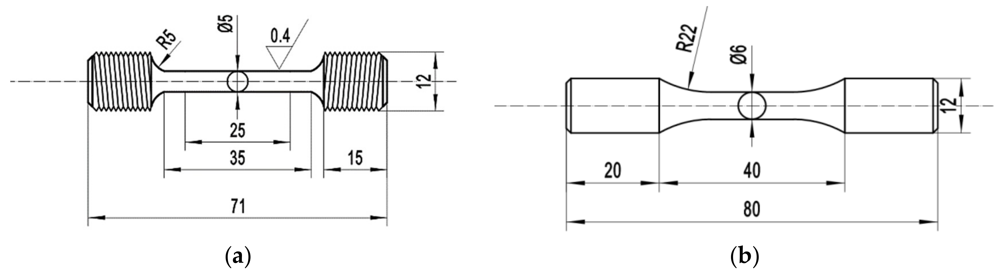
2.1. Sample Preparation

The substrate material employed in this study was annealed Ti-6Al-4V alloy with the following composition (wt.%): 6.25% Al, 4.23% V, 0.22% Fe, 0.13% O, 0.011% C, 0.018% N, 0.001% H, and Ti bal. From this material, tensile and fatigue specimens were machined according to the Chinese standards GB/T 228.1-2010 [18] and GB/T 4337-2015 [19], respectively. Additionally, a few parallelepiped samples (50 mm × 20 mm × 3 mm) were employed for the purpose of coating property characterization.
Figure 1a,b illustrates the sketches of the tensile and fatigue specimens in which all dimensions are given in mm. All the samples were machined with utmost care in order to avoid the introduction of undesirable residual stresses. Surface polishing was further employed for the elimination of the remaining circumferential notches.

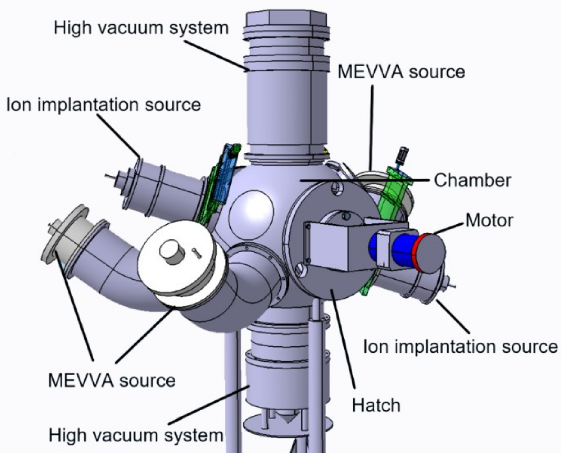
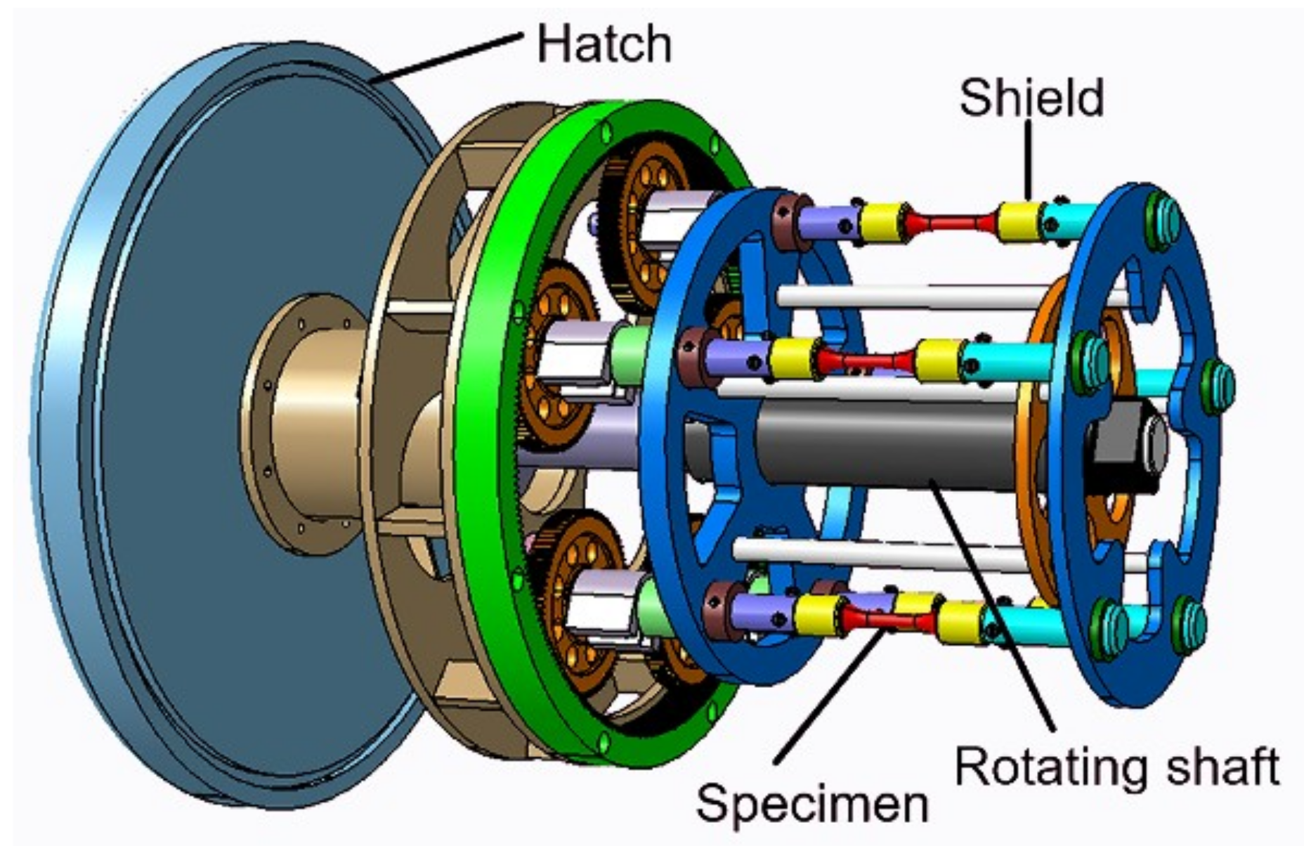
2.2. Magnetic Filtered Cathoic Vacuum Arc (MFCVA) Setup

The 3-D model of a magnetic filtered cathodic vacuum arc (MFCVA) deposition apparatus is shown in Figure 2. Its main components are three metal vapor vacuum arc (MEVVA) ion sources with 90° bent copper pipe, two ion implantation sources, a rotating shaft in the horizontal direction driven by a motor and bracket which can be installed, two high vacuum systems, and a power supply control system. The 90° bent copper pipe forms an electromagnetic field to filter the large neutral particles which could cause droplets and other defects on the coating. In contrast to other filter cathodic vacuum arc (FCVA) deposition processes, here an ion implantation source was utilized for substrate surface modification, which can enhance the adhesion between the coating and substrate.
The rotating bracket shown in Figure 3 was specifically designed for homogeneous coating deposition on dog-bone shape specimens. Five tensile, fatigue or plate samples can be equipped on the rotating bracket. The rotation bracket mounted on the shaft was driven by the motors. The planetary gear took the specimen rotated along the internal ring gear mounted on the fixture, and a shield was mounted on both sides of the specimen for protecting the grip section from being coated. In order to demonstrate the effectiveness of this tooling, the coating thickness uniformity experiment was carried out, and the experiment details are shown below.

2.3. Coating Deposition and Characterization

The basic coating deposition process is shown as follows. Before the deposition process, the specimens were ultrasonically cleaned in the acetone for 10 min and then cleaned via ethanol and dried. The rotation speed of the bracket was fixed at 20 r/min for all deposition conditions. The ion implantation experiment started when pressure of the chamber reached 5 × 10⁻³ Pa and the temperature met the corresponding requirement. Subsequently, the buffer layer was introduced. Finally, the hard coating was deposited.

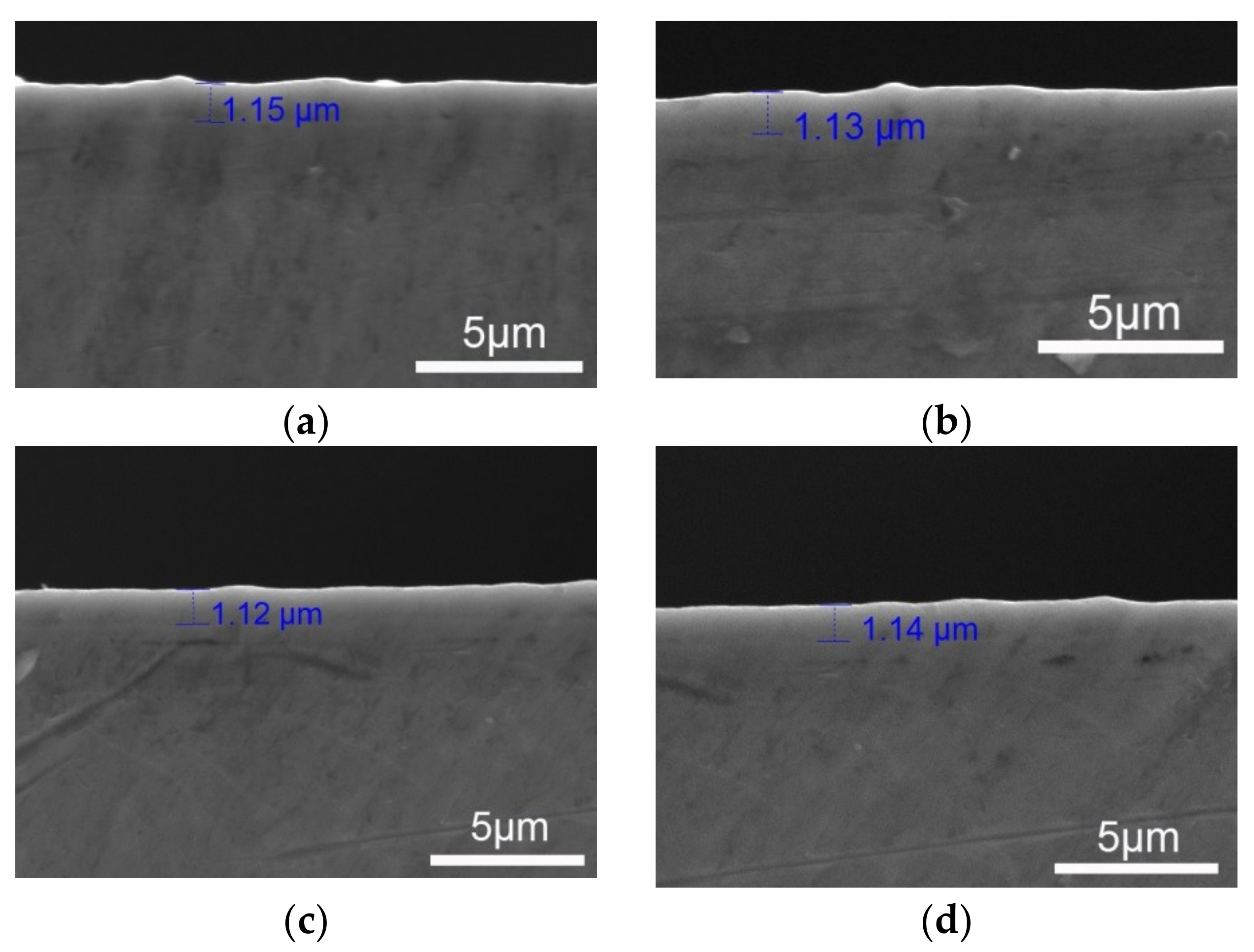
2.3.1. Deposition and Characterization of Coating Thickness Uniformity on Dog-Bone Shape Sample

Deposition parameters of the coating thickness uniformity examination on the dog-bone shape sample are shown in Table 1. The tensile specimen shown in Figure 1a was used in this experiment. During this deposition process, the buffer layer was not introduced, and the inspection was carried out on the middle cross-section face that was perpendicular to the axial of the tensile specimen, and four areas 90° apart were selected.

2.3.2. CrN and TiN Coating Deposition

Deposition parameters of the CrN and TiN coatings on the tensile samples are shown in Figure 1a, the fatigue sample is shown in Figure 1b, as well as the parallelepiped flat samples (50 mm × 20 mm × 3 mm) which are shown in Table 2 and Table 3, respectively.

2.3.3. Coating Characterization

The X-ray diffractometer (XRD, Holland Panalytical X’Pert Pro, Almelo, The Netherlands) with a Cu-Kα radiation source and a step size of 0.06° was used to determine phase constitutions of both the coatings and the substrate. Cross-sectional samples of coated substrate for thickness uniformity inspection were prepared using mechanical polishing. The thickness of deposited coating on the dog-bone shape specimens and the fracture surfaces of the uniaxial tensile and fatigue test specimens were examined by scanning electron microscope (SEM) techniques (MIRA 3, TESCAN, Brno, Czech Republic). Regarding mechanical properties of the coating, the hardness and elastic modulus of the coatings were measured via nanoindentation tester (Nano indenter G200, Agilent Technologies, Santa Clara, CA, USA). The penetration depth of the indenter was set to 300 nm and five nanoindentations were performed under each condition. The adhesion force test was conducted by scratch tester (WS-2005). Scratches of 4 mm length were made on each coating surface with a Rockwell C diamond spherical indenter under a load increasing continuously at a rate of 80 N/min, and four scratches were performed for each coating. The mechanical properties tests of the coating as well as the adhesion force test between the coatings and the substrate were conducted on the parallelepiped flat samples.

2.4. Fatigue and Mechanical Tests

Fatigue tests were carried out under the rotating bending condition (R = −1), employing a PQ-6 type rotating bending testing machine (Qingshan, Yinchuan, China) at a frequency of 35 Hz. A fatigue test was terminated if the sample failed or survived by 1 × 10⁶ cycles. The tests were all carried out in air at room temperature. The mechanical properties tests of both the uncoated and coated specimens were conducted by tensile tests, which were carried out on a computer-controlled WDW-300 electronic universe test machine (Kexin, Changchun, China) at a cross-head speed of 2 mm/min. A contacting Instron extensometer was used to measure strain within the sample gauge upon loading. For the CrN and TiN coated and uncoated samples, three tensile specimens and seven fatigue specimens were prepared for corresponding tests.

3. Results and Discussion

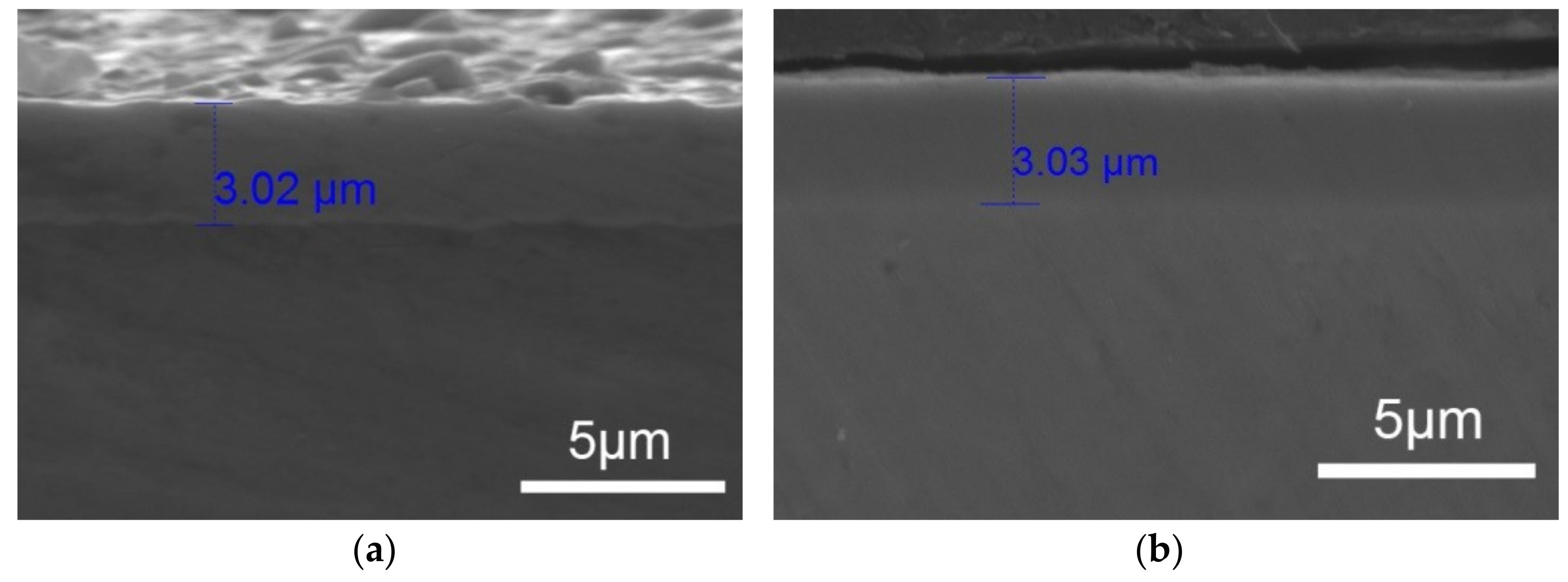
3.1. Thickness Uniformity of Coating on Dog-Bone Shape Samples

The TiN coating deposition for thickness uniformity examination on the tensile specimens shown in Figure 1a was carried out according to Table 2. The thickness uniformity of the deposited TiN coating on the middle cross-section face that was perpendicular to the axial of the tensile specimen is shown in Figure 4. It can be seen from Figure 4 that in four areas 90° apart, the thickness ranged from 1.12 to 1.15 μm which indicated that the coating was uniformly distributed, although a few nanometers difference existed. This meant that the coating deposited through this bracket can get a homogeneous distribution along the dog-bone shape specimen.

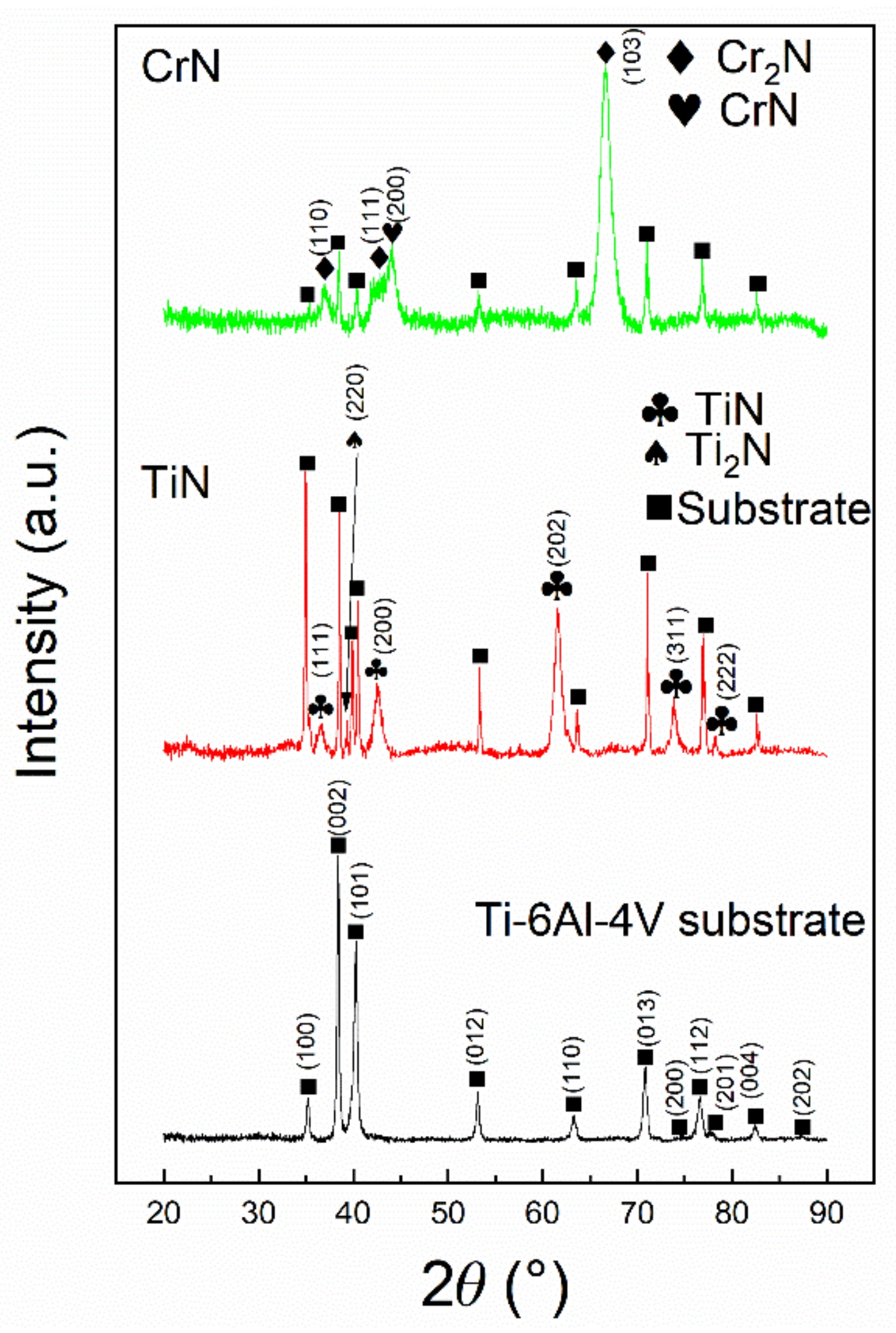
3.2. Characterization of the Coating

Figure 5 shows the XRD patterns of the Ti-6Al-4V substrate, CrN and TiN coatings. It can be seen from Figure 5 that for the CrN coating, a preferred orientation Cr2N (103) and relative weak peaks belonging to CrN (111) appeared, indicating that the coating consisted of a trigonal-Cr2-N (COD No. 4311894) and fcc-CrN (COD No. 9008619) mixed phase. For the TiN coating, compared with the strong peaks belonging to the Ti-6Al-4V, relative weak peaks belonging to fcc-TiN (COD No. 1011099) and tetragonal-Ti2N (COD No. 1101043) were identified. In addition, peaks belong to Ti-6Al-4V (COD No. 9016190) were marked because the X-ray can penetrate through the as-deposited thin coatings and reach the substrates.
Figure 6 shows the cross-sectional SEM micrographs of the as-deposited CrN and TiN coating on dog-bone shape specimens. It can be seen from Figure 6 that the coating bound well with the substrate and the thickness of both coating were 3.02 and 3.03 μm, respectively. The elastic modulus, hardness and adhesion force of the CrN coating and TiN coating are shown in Figure 7. It can be seen from Figure 7 that the TiN coating has a relatively better mechanical property in comparison with the CrN coating. Based on the value shown in Figure 7, the ration H3/E2 (H for coating hardness while E for coating elastic modulus) of CrN and TiN coating is 0.405 and 0.169, respectively. This indicated that the TiN coating has higher plastic deformation resistance than the CrN coating [20,21,22,23].

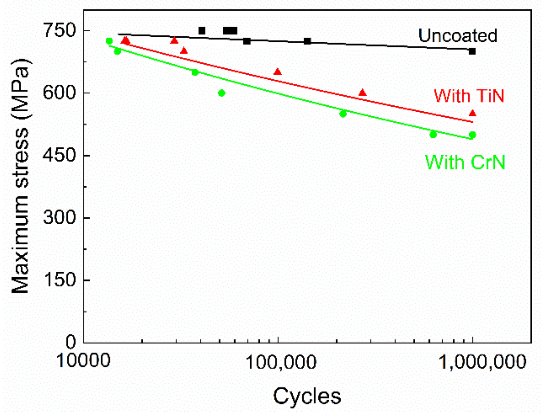
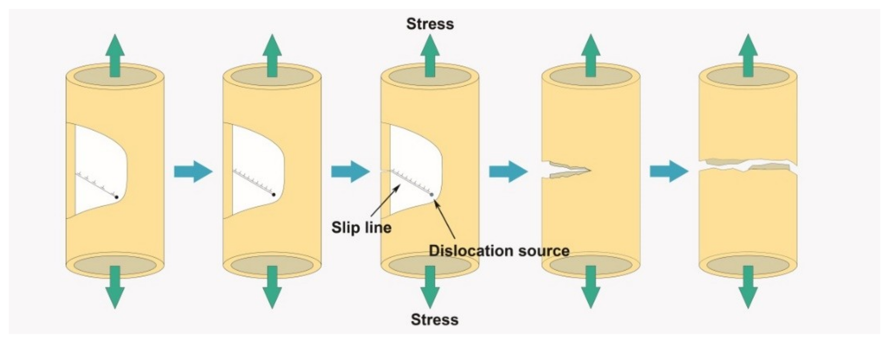
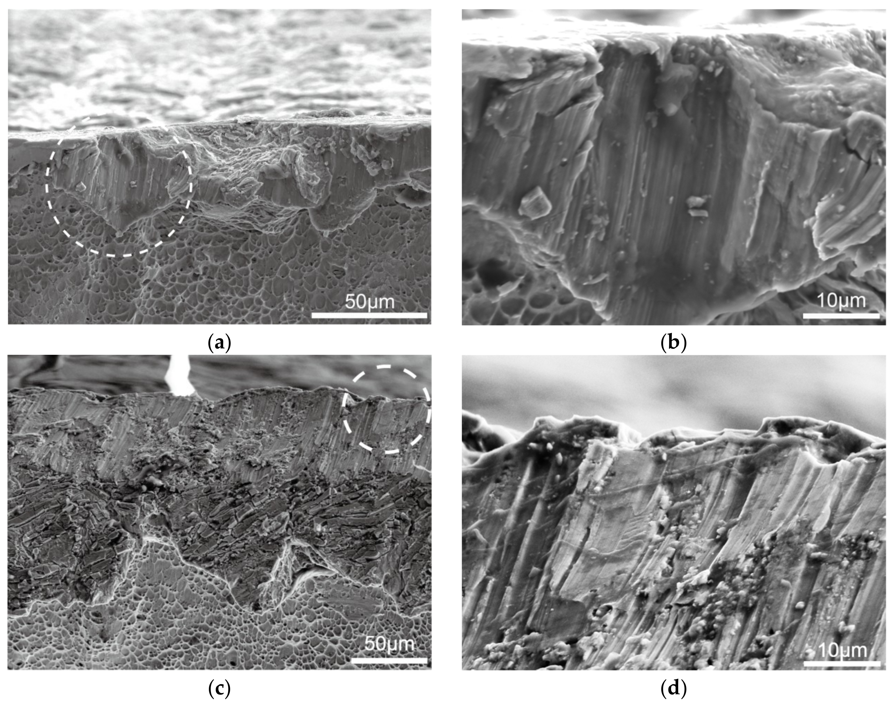
3.3. Fatigue Behavior and Discussion

Rotating bending test results for the uncoated Ti-6Al-4V substrate and the CrN and TiN coated samples are shown in Figure 8. Results indicated that CrN and TiN coatings reduce the base material fatigue strength from lower-cycle life to higher-cycle life regimes, and that better fatigue performances can be observed for TiN coated samples compared with CrN.
For a maximum applied stress equal to 700 MPa, which represents 77% of the ultimate tensile strength, Ti-6Al-4V alloy presented a fatigue life of 106 cycles. For the same stress level, the number of cycles to failure for the CrN and TiN coated Ti-6Al-4V was 14968 and 32820 cycles, respectively. For the CrN and TiN coated samples the fatigue limit was about 500 and 550 MPa, respectively. In comparison with the uncoated Ti-6Al-4V substrate, the reductions of fatigue limit of the CrN and TiN coated samples are 29% and 21%, respectively.
Figure 9a,b shows the outward appearance of the CrN and TiN coated Ti-6Al-4V after the rotating bending fatigue test at 725 MPa. It can be seen from Figure 9a,b that no coating spallation phenomenon was observed. In addition, for the rest fatigue test specimen, coating spallation was also not observed, which meant that the CrN and TiN coatings prepared in this study had a promising adhesion force.
The fracture surfaces for the CrN coated Ti-6Al-4V tested at 725 MPa with 13574 cycles until fracture are indicated in Figure 10. One fatigue nucleation is presented in Figure 10a. At higher magnification, Figure 10c shows that cracks were found on the substrate under the crack coating, which meant that cracks initiated at the coating surface and propagated throughout the base material. Figure 11 shows the fracture surfaces for the TiN coated Ti-6Al-4V tested at 650 MPa with 99619 cycles until fracture. A nucleation site was also found on the periphery of the sample and coating cracking was observed in Figure 11b.
The fatigue strength reduction mechanism can be based on the coating characterization results shown above, where the TiN coating has a better plastic deformation resistance than the CrN coating. This means that under same applied bending stress and rotating condition, the CrN coating tends to crack easily compared with the TiN coating. As the coating has a relatively good adhesion to the substrate in our study, the crack in the coating propagates through the buffer coating to the base material and causes the specimen failure.

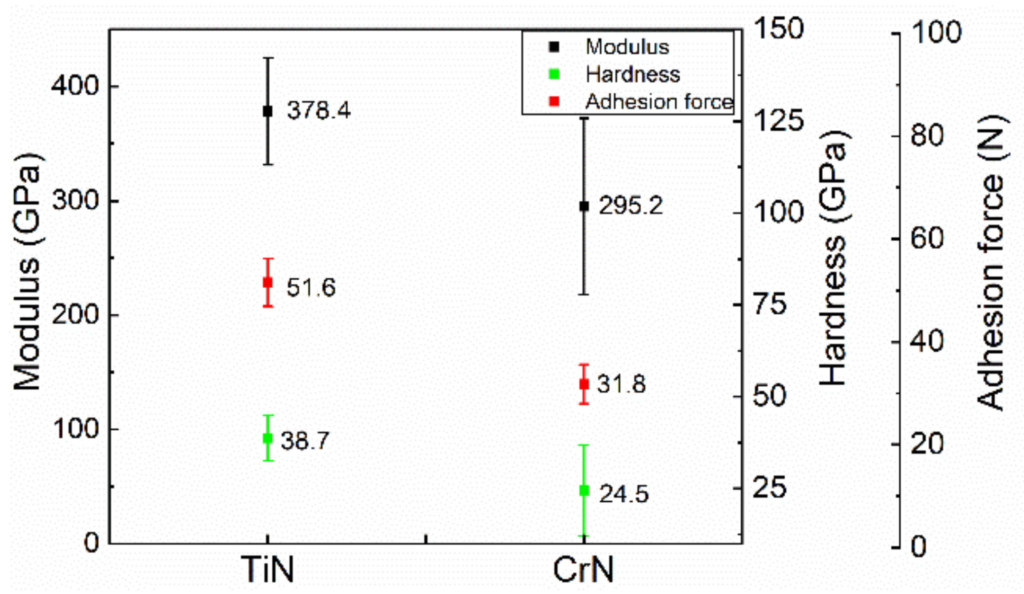
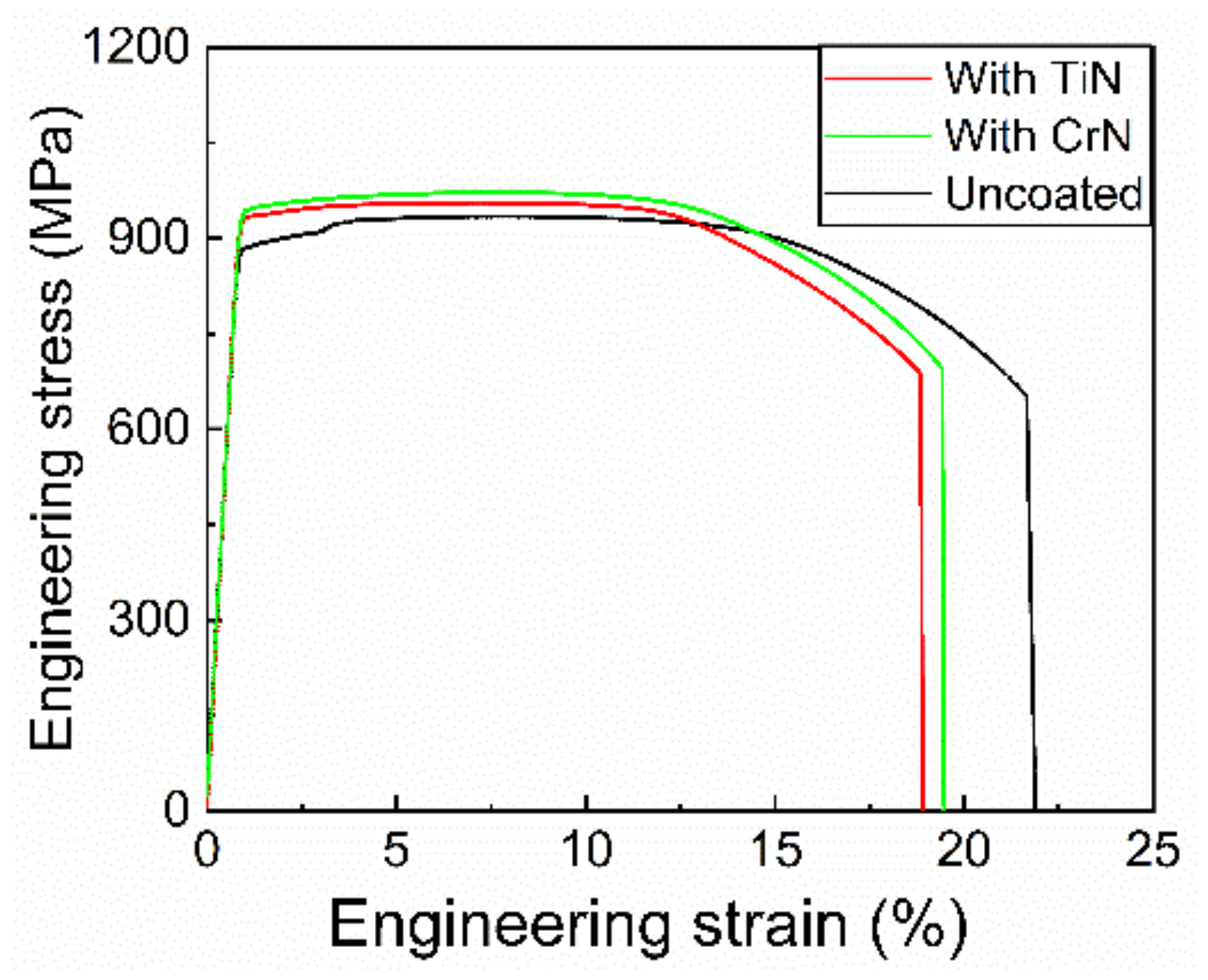
3.4. Mechanical Properties and Discussion

Figure 12 shows the tensile engineering stress-strain curves of the uncoated sample, CrN, and TiN coated sample. In comparison with the uncoated Ti-6Al-4V sample, the mean ultimate strength and mean yield strength increase from 911 and 892 to 975 and 931 MPa in the CrN coated sample, respectively, and to 959 and 933 MPa in the TiN coated sample. Meanwhile, the failure elongation decreases from 21.9% to 19.25% and 19% in the CrN and TiN, respectively. This means that both hard coatings could deteriorate the mechanical properties of the Ti-6Al-4V substrate. The mechanisms of ultimate strength increment and yield strength increment as well as the failure elongation reduction are illustrated in Figure 13 and discussed below.
During the loading process in the uniaxial tensile test, the substrate and coating are experiencing elastic deformation together in the early stage. Then, as the applied stress increases, dislocation sources in the substrate start to emit dislocation to the boundary of the substrate, and are counteracted by the hard coating. This could delay the emission of dislocation in the substrate compared to the free surface. Although mechanical properties differences exist between the coatings and substrate, experiments and molecular dynamic simulations have demonstrated that the coatings could affect the plastic deformation of the substrate [24]. This is attributed to the different lattice parameters and crystalline structures of the brittle coatings from that of the metal substrate. The brittle TiN and CrN coatings shown in Figure 6a, b can effectively restrain dislocations to breakout from the substrate [25,26,27]. Consequently, the emitted dislocations will pile up against the interface along the slip plane, as schematically illustrated in Figure 13. The piled-up dislocation could produce a stress counteracting the applied stress, which is enough for causing the free substrate crack [28,29]. This means that higher applied stress is required to crack the coated sample. Furthermore, this could cause high-stress concentration at the head of pile-up dislocation. The hard coating may first crack under such conditions, and the crack in the circumference may propagate into the substrate at a higher velocity compared to the free substrate due to the poor plastic performance of the hard coating [30]. Consequently, the coated sample could fail in a relative smaller elongation. Additionally, the fracture morphology belonging to brittle cracking is found on the ductile Ti-6Al-4V substrate under tensile loads as shown in Figure 14. This may be due to the high stress at the head of the piled-up location and the high-strain rate of coating cracking that the crack initiated in the coating could propagate to the substrate in a very short time [31,32].
In our study, the coating thickness is only 3 μm so that the influence on the mechanical property of the Ti-6Al-4V substrate may be negligible. Nevertheless, we believe that the coating-substrate interaction in short ranges will be stronger while the coating thickness increases, and that coating with better toughness, such as with Ti and Ni metal coating, may introduce different results compared with the hard coating.

4. Conclusions

In this study, the effect of uniformly distributed CrN and TiN hard coatings with thickness of about 3 μm on the fatigue and mechanical properties of Ti-6Al-4V substrate were investigated by rotating bending and uniaxial tensile test. The fatigue results showed that both hard coatings can decrease the fatigue properties of Ti-6Al-4V substrate. Compared with the TiN coating that has better mechanical properties, the CrN coating can induce a more remarkable reduction on the fatigue property of Ti-6Al-4V substrate. For mechanical properties, the hard coating coated samples have a relative higher ultimate strength, yield strength, and lower elongation compared with the Ti-6Al-4V substrate. The main reason that can be concluded for this is that, on the one hand, hard coating can impede the release of dislocation in the substrate, and higher stress is then needed for a fracture. On the other hand, compared with the ductile Ti-6Al-4V substrate, brittle coating can fracture and propagate at a higher velocity to the substrate and induce the substrate failure.

Author Contributions

Data curation, J.C.; formal analysis, Z.Z.; funding acquisition, G.H.; writing–original draft, Z.Z.; writing–review and editing, G.H. and G.Y.

Funding

This research was funded by National Science and Technology Major Project (2017-VII-0012-0107).

Conflicts of Interest

The authors declare no conflict of interest.

References

  1. Shahmir, H.; Langdon, T.G. Using heat treatments, high-pressure torsion and post-deformation annealing to optimize the properties of Ti-6Al-4V alloys. Acta Mater. 2017, 141, 419–426. [Google Scholar] [CrossRef] [Green Version]
  2. Wu, Z.H.; Kou, H.C.; Tang, B.; Fan, J.K.; Chen, Y.; Li, J.S. Stress relaxation induced morphological evolution and texture weakening of α phase in Ti-6Al-4V alloy. Mater. Lett. 2019, 236, 148–151. [Google Scholar] [CrossRef]
  3. Nabhani, M.; Razavi, R.S.; Barekat, M. Corrosion study of laser cladded Ti-6Al-4V alloy in different corrosive environments. Eng. Fail. Anal. 2019, 97, 234–241. [Google Scholar] [CrossRef]
  4. Geng, M.; He, G.; Sun, Z.; Chen, J.; Yang, Z.; Li, Y. Corrosion damage mechanism of TiN/ZrN nanoscale multilayer anti-erosion coating. Coatings 2018, 8, 400. [Google Scholar] [CrossRef]
  5. Chen, J.; Geng, M.; Li, Y.; Yang, Z.; Chai, Y.; He, G. Erosion Resistance and damage mechanism of TiN/ZrN nanoscale multilayer coating. Coatings 2019, 9, 64. [Google Scholar] [CrossRef]
  6. Chen, Z.; Zhao, J.; Meng, X.; Li, J. Evaluation of fatigue resistance of a gradient CrNx coating applied to turbine blades. Mater. Sci. Eng. A 2010, 527, 1436–1443. [Google Scholar] [CrossRef]
  7. Gelfi, M.; La Vecchia, G.M.; Lecis, N.; Troglio, S. Relationship between through-thickness residual stress of CrN-PVD coatings and fatigue nucleation sites. Surf. Coat. Technol. 2005, 192, 263–268. [Google Scholar] [CrossRef]
  8. Deng, J.; Wu, F.; Lian, Y.; Xing, Y.; Li, S. Erosion wear of CrN, TiN, CrAlN, and TiAlN PVD nitride coatings. Int. J. Refract. Met. Hard Mater. 2012, 35, 10–16. [Google Scholar] [CrossRef]
  9. Akbari, A.; Riviere, J.P.; Templier, C.; Le Bourhis, E. Structural and mechanical properties of IBAD deposited nanocomposite Ti-Ni-N coatings. Surf. Coat. Technol. 2006, 200, 6298–6302. [Google Scholar] [CrossRef]
  10. Wang, Q.; Zhou, F.; Wang, C.; Yuen, M.-F.; Wang, M.; Qian, T.; Matsumoto, M.; Yan, J. Comparison of tribological and electrochemical properties of TiN, CrN, TiAlN and a-C:H coatings in simulated body fluid. Mater. Chem. Phys. 2015, 158, 74–81. [Google Scholar] [CrossRef]
  11. Guo, T.; Qiao, L.; Pang, X.; Volinsky, A.A. Brittle film-induced cracking of ductile substrates. Acta Mater. 2015, 99, 273–280. [Google Scholar] [CrossRef]
  12. Bandyopadhyay, R.; Mello, A.W.; Kapoor, K.; Reinhold, M.P.; Broderick, T.F.; Sangid, M.D. On the crack initiation and heterogeneous deformation of Ti-6Al-4V during high cycle fatigue at high R ratios. J. Mech. Phys. Solids 2019, 129, 61–82. [Google Scholar] [CrossRef]
  13. Ren, Y.M.; Lin, X.; Guo, P.F.; Yang, H.O.; Tan, H.; Chen, J.; Li, J.; Zhang, Y.Y.; Huang, W.D. Low cycle fatigue properties of Ti-6Al-4V alloy fabricated by high-power laser directed energy deposition: Experimental and prediction. Int. J. Fatigue 2019, 127, 58–73. [Google Scholar] [CrossRef]
  14. Costa, M.Y.P.; Venditti, M.L.R.; Cioffi, M.O.H.; Voorwald, H.J.C.; Guimarães, V.A.; Ruas, R. Fatigue behavior of PVD coated Ti-6Al-4V alloy. Int. J. Fatigue 2011, 33, 759–765. [Google Scholar] [CrossRef]
  15. Bai, Y.; Xi, Y.; Gao, K.; Yang, H.; Pang, X.; Yang, X.; Volinsky, A.A. Brittle coating effects on fatigue cracks behavior in Ti alloys. Int. J. Fatigue 2019, 125, 432–439. [Google Scholar] [CrossRef]
  16. Costa, M.Y.P.; Cioffi, M.O.H.; Venditti, M.L.R.; Voorwald, H.J.C. Fatigue fracture behavior of Ti-6Al-4V PVD coated. Procedia Eng. 2010, 2, 1859–1864. [Google Scholar] [CrossRef]
  17. Lee, C.M.; Chu, J.P.; Chang, W.Z.; Lee, J.W.; Jang, J.S.C.; Liaw, P.K. Fatigue property improvements of Ti-6Al-4V by thin film coatings of metallic glass and TiN: A comparison study. Thin Solid Films 2014, 561, 33–37. [Google Scholar] [CrossRef]
  18. AQSIQ. Metallic Materials-tensile Testing–Part 1: Method of Test at Room Temperatures GB/T228.1; Standards Press of China: Beijing, China, 2010. (in Chinese) [Google Scholar]
  19. AQSIQ. Metallic Materials-Fatigue Testing–Rotating bar bending method GB/T4337; Standards Press of China: Beijing, China, 2015. (in Chinese) [Google Scholar]
  20. Belov, D.S.; Blinkov, I.V.; Sergevnin, V.S.; Smirnov, N.I.; Volkhonskii, A.O.; Bondarev, A.V.; Lobova, T.A. Abrasive, hydroabrasive, and erosion wear behaviour of nanostructured (Ti,Al)N-Cu and (Ti,Al)N-Ni coatings. Surf. Coat. Technol. 2018, 338, 1–13. [Google Scholar] [CrossRef]
  21. Sha, C.; Munroe, P.; Zhou, Z.; Xie, Z. Effect of Ni content on the microstructure and mechanical behaviour of CrAlNiN coatings deposited by closed field unbalanced magnetron sputtering. Surf. Coat. Technol. 2019, 357, 445–455. [Google Scholar] [CrossRef]
  22. Bartosik, M.; Rumeau, C.; Hahn, R.; Zhang, Z.L.; Mayrhofer, P.H. Fracture toughness and structural evolution in the TiAlN system upon annealing. Sci. Rep. 2017, 7, 16476. [Google Scholar] [CrossRef]
  23. Ibrahim, R.N.; Rahmat, M.A.; Oskouei, R.H.; Singh Raman, R.K. Monolayer TiAlN and multilayer TiAlN/CrN PVD coatings as surface modifiers to mitigate fretting fatigue of AISI P20 steel. Eng. Fract. Mech. 2015, 137, 64–78. [Google Scholar] [CrossRef]
  24. Pei, L.; Lu, C.; Zhao, X.; Zhang, L.; Cheng, K.; Michal, G.; Tieu, K. Brittle versus ductile behaviour of nanotwinned copper: A molecular dynamics study. Acta Mater. 2015, 89, 1–13. [Google Scholar] [CrossRef] [Green Version]
  25. Guo, T.; Chen, Y.; Cao, R.; Pang, X.; He, J.; Qiao, L. Cleavage cracking of ductile-metal substrates induced by brittle coating fracture. Acta Mater. 2018, 152, 77–85. [Google Scholar] [CrossRef]
  26. Fertig, R.S.; Baker, S.P. Dislocation dynamics simulations of dislocation interactions and stresses in thin films. Acta Mater. 2010, 58, 5206–5218. [Google Scholar] [CrossRef]
  27. Bertin, B.; Durinck, J.; Colin, J. Dislocation emission and crack propagation during thin film buckling on substrate. Int. J. Solids Struct. 2019. [Google Scholar] [CrossRef]
  28. Guo, T.; He, J.; Pang, X.; Volinsky, A.A.; Su, Y.; Qiao, L. High temperature brittle film adhesion measured from annealing-induced circular blisters. Acta Mater. 2017, 138, 1–9. [Google Scholar] [CrossRef]
  29. Wu, K.; Zhang, J.Y.; Li, J.; Wang, Y.Q.; Liu, G.; Sun, J. Length-scale-dependent cracking and buckling behaviors of nanostructured Cu/Cr multilayer films on compliant substrates. Acta Mater. 2015, 100, 344–358. [Google Scholar] [CrossRef]
  30. Huang, C.; Gao, X. Development of a phase field method for modeling brittle and ductile fracture. Comput. Mater. Sci. 2019, 169, 109089. [Google Scholar] [CrossRef]
  31. Cramer, T.; Wanner, A.; Gumbsch, P. Energy dissipation and path instabilities in dynamic fracture of silicon single crystals. Phys. Rev. Lett. 2000, 85, 788–791. [Google Scholar] [CrossRef]
  32. Ye, T.; Suo, Z.; Evans, A.G. Thin film cracking and the roles of substrate and interface. Int. J. Solids Struct. 1992, 29, 2639–2648. [Google Scholar] [CrossRef]
Figure 1. Diagrams of the tensile and fatigue specimens employed in this study (unit: mm). (a) Tensile test specimen, (b) rotating bending fatigue test specimen.
Coatings 09 00689 g001
Figure 2. The 3-D model of MFCVA setup.
Coatings 09 00689 g002
Figure 3. The rotating bracket for homogeneous coating deposition.
Coatings 09 00689 g003
Figure 4. Thickness uniformity investigation of the TiN coating at four areas 90° apart on the middle cross-section face perpendicular to the axial of the specimen. (a) 0°; (b) 90°; (c) 180°; (d) 270°.
Coatings 09 00689 g004
Figure 5. XRD profile of the CrN coating, TiN coating, and Ti-6Al-4V substrate.
Coatings 09 00689 g005
Figure 6. Cross-section SEM test results of CrN and TiN coated samples. (a) CrN coating, (b) TiN coating.
Coatings 09 00689 g006
Figure 7. Elastic modulus, hardness and adhesion force of the CrN coating and TiN coating.
Coatings 09 00689 g007
Figure 8. Rotation-bend fatigue test results of uncoated, CrN and TiN coated samples.
Coatings 09 00689 g008
Figure 9. Outward appearance of the CrN and TiN coated samples after fatigue tests. (a) CrN coated fatigue specimen, (b) TiN coated fatigue specimen.
Coatings 09 00689 g009
Figure 10. Fracture surface of the CrN coated sample at σ = 725 MPa, 13574 cycles. (a) Macroscopic morphology of the fracture surface, (b) substrate crack morphology in the white dashed circle of (a), (c) coating crack morphology under the white arrow of (b) at high magnification. The regions of crack initiation, crack propagation, and instant rupture are marked by A, B, and C in (a), respectively.
Coatings 09 00689 g010aCoatings 09 00689 g010b
Figure 11. Fracture surface of the TiN coated sample σ = 650 MPa, 99619 cycles. (a) Macroscopic morphology of fracture surface, (b) coating crack morphology in the white dashed circle of (a) at high magnification.
Coatings 09 00689 g011
Figure 12. Tensile engineering stress-strain curves of the uncoated sample, CrN, and TiN coated sample.
Coatings 09 00689 g012
Figure 13. Schematic illustration of coated sample under tensile stress.
Coatings 09 00689 g013
Figure 14. Brittle fracture area morphology of the coated sample. (a) Brittle fracture area morphology of the CrN coated sample, (b) fracture morphology in the white dashed circle of (a) at high magnification, (c) Brittle fracture area morphology of the TiN coated sample, (d) fracture morphology in the white dashed circle of (c) at high magnification.
Coatings 09 00689 g014
Table 1. Deposition parameters of coating thickness uniformity examination.
Coating TypeStepSourceBias VoltageArc CurrentDurationNitrogen Flow RateTemperature
TiN coatingIon implantationTi (99.95%)10 kV40 min400 °C
Coating depositionTi (99.95%)250 V115 A70 min50 sccm500 °C
Table 2. Deposition parameters of CrN coating.
StepSourceBias VoltageArc CurrentDurationNitrogen Flow RateTemperature
Ion implantationCr (99.95%)8 kV50 min300 °C
Buffer layer depositionCr (99.95%)40 V120 A40 min400 °C
Coating depositionCr (99.95%)40 V120 A720 min18 sccm400 °C
Table 3. Deposition parameters of TiN coating.
StepSourceBias VoltageArc CurrentDurationNitrogen Flow RateTemperature
Ion implantationTi (99.95%)10 kV40 min400 °C
Buffer layerTi (99.95%)250 V110 A30 min600 °C
Coating depositionTi (99.95%)250 V110 A70 min35 sccm600 °C

