Article

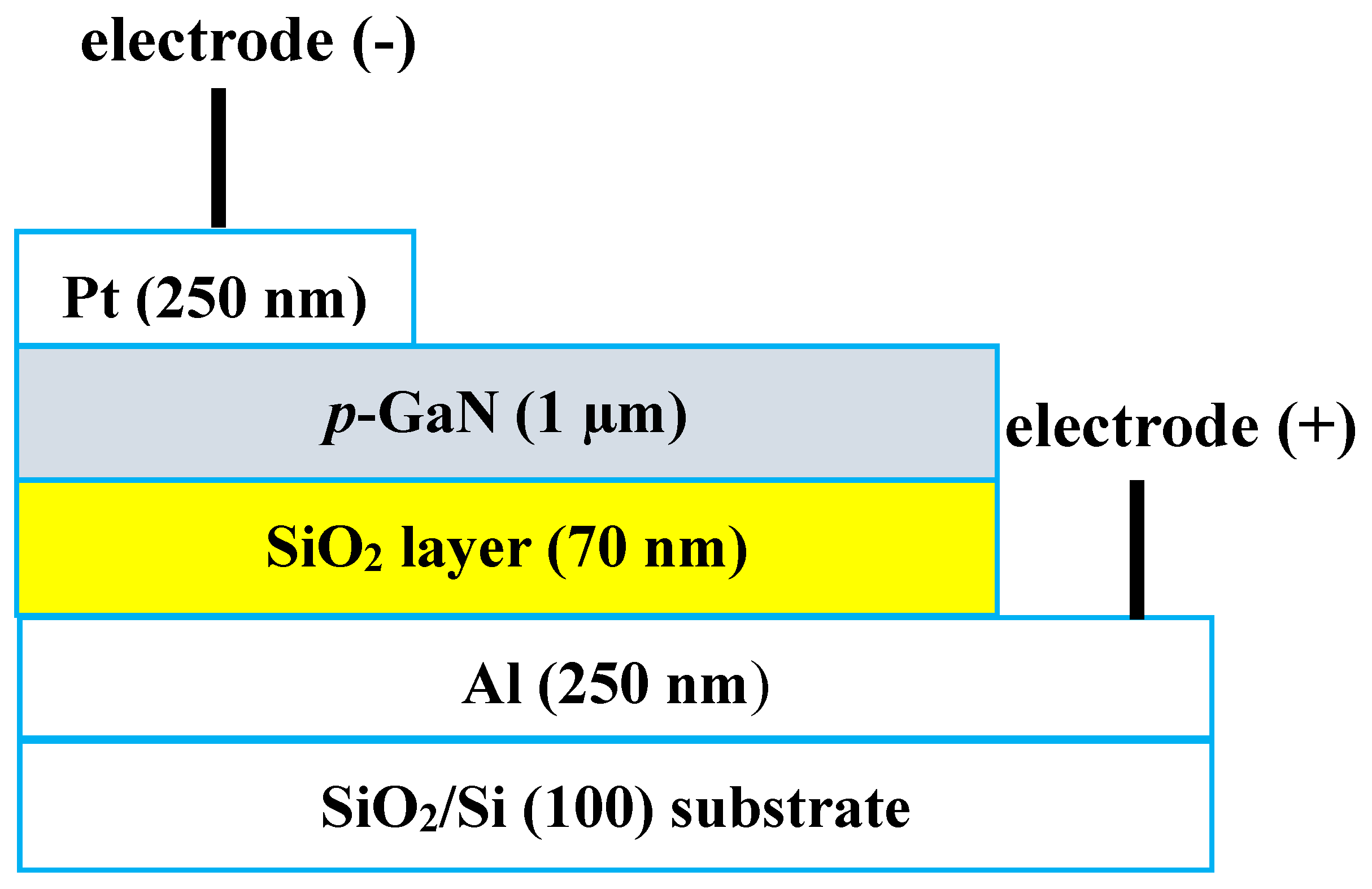
Electrical and Structural Properties of All-Sputtered Al/SiO2/p-GaN MOS Schottky Diode

1
School of Basic Sciences, Tra Vinh University, Tra Vinh 87000, Vietnam
2
Department of Materials Science and Engineering, National Taiwan University of Science and Technology, Taipei 10607, Taiwan
3
School of Engineering and Technology, Tra Vinh University, Tra Vinh 87000, Vietnam
4
School of Engineering and Technology, Can Tho University, Can Tho 94000, Vietnam
*
Authors to whom correspondence should be addressed.
Coatings 2019, 9(10), 685; https://doi.org/10.3390/coatings9100685
Submission received: 22 September 2019 / Revised: 10 October 2019 / Accepted: 14 October 2019 / Published: 21 October 2019
(This article belongs to the Special Issue Advanced Strategies in Thin Film Engineering by Magnetron Sputtering)

Abstract

:
The all-sputtered Al/SiO2/p-GaN metal-oxide-semiconductor (MOS) Schottky diode was fabricated by the cost-effective radio-frequency sputtering technique with a cermet target at 400 °C. Using scanning electron microscope (SEM), the thicknesses of the electrodes, insulator SiO2 layer, and p-GaN were found to be ~250 nm, 70 nm, and 1 µm, respectively. By Hall measurement of a p-Mg-GaN film on an SiO2/Si (100) substrate at room temperature, the hole’s concentration (Np) and carrier mobility (μ) were found to be Np = 4.32 × 1016 cm−3 and μ = 7.52 cm2·V−1·s−1, respectively. The atomic force microscope (AFM) results showed that the surface topography of the p-GaN film had smoother, smaller grains with a root-mean-square (rms) roughness of 3.27 nm. By I–V measurements at room temperature (RT), the electrical properties of the diode had a leakage current of ~4.49 × 10⁻⁸ A at −1 V, a breakdown voltage of −6 V, a turn-on voltage of ~2.1 V, and a Schottky barrier height (SBH) of 0.67 eV. By C–V measurement at RT, with a frequency range of 100–1000 KHz, the concentration of the diode’s hole increased from 3.92 × 1016 cm−3 at 100 kHz to 5.36 × 1016 cm−3 at 1 MHz, while the Fermi level decreased slightly from 0.109 to 0.099 eV. The SBH of the diode at RT in the C–V test was higher than in the I–V test because of the induced charges by dielectric layer. In addition, the ideality factor (n) and series resistance (Rs) determined by Cheung’s and Norde’s methods, other parameters for MOS diodes were also calculated by C–V measurement at different frequencies.

1. Introduction

GaN-based semiconductor materials are currently of interest for the fabrication of electronic devices such as the metal-semiconductor (MS) and MOS Schottky diodes, light-emitting diodes (LEDs), photo-detector, metal-oxide-semiconductor field-effect transistors (MOSFETs), and heterojunction field-effect transistors (HFETs). [1,2,3,4,5]. Previous studies created the thin, high-quality insulator layer between the metal and semiconductor that is used to create a metal-oxide-semiconductor (MOS) structure, which was an important factor for the high-performance of MOS devices [6,7,8,9,10]. Researchers investigated the contact of MOS layers via various approaches, e.g., Al/HfO2/p-Si [7], Pt/oxide/n-InGaP [10], Pt/SiO2/n-InGaN [11], Pd/NiO/GaN [12], Au/SiO2/n-GaN [13], Au/SnOx/n-LTPS/glass [14], Pt/SiO2/n-GaN [6,15], Pt/Oxide/Al0.3Ga0.7As [16], Pd/HfO2/GaN [17], and Al/SnO2/p-Si (111) [18]. Due to the presence of the oxide layer, several parameters can be applied to improve the characteristics of electronic devices. Bengi et al. reported the parameters of the Al/HfO2/p-Si MOS device, which was tested by CV measurement. Their SBHs were shown from 0.17 to 0.98 eV, in the temperature range 300–400 K [7]. Karadeniz et al. investigated the Al/SnO2/p-Si (111) diode using spray deposition. The MOS diode showed a Schottky barrier height (SBH) of 0.52 V, an ideality factor of 2.4, and series resistance of 66 Ω [18]. Liu et al. studied the influence of hydrogen adsorption on the Pd/AlGaN-based MOS diode with SiO2 passivation [19]. Their SBHs were reduced from 0.98 to 0.75 eV under exposure to a 1% H2/air gas.
In this study, the radio-frequency (RF) reactive sputtering technique was used to design the Al/SiO2/p-GaN MOS Schottky diode because of advantages such as low deposition temperature, low cost, and safety [3,6,11]. With the support of the parameters and using the RF technique, our diode was fabricated below 400 °C. The characteristics of the MOS Schottky diode were tested using IV and CV measurements. The parameters of the diode were calculated by thermionic emission (TE) mode using Cheung’s and Norde’s methods.

2. Materials and Methods

Figure 1 shows the modeling of the Al/SiO2/p-GaN MOS Schottky diode based on p-GaN film. First, for the Schottky contacts, an Al layer was sputtered on an SiO2/Si (100) substrate at 200 °C for 20 min using a pure Al (99.99%) target, and RF power of 80 W. To construct the MOS Schottky diodes, an interlayer between Al and p-GaN was designed by depositing SiO2. The SiO2 film was sputtered on an Al/SiO2/Si (100) substrate at 100 °C for 10 min using a quartz target. The RF power remained at 80 W and the Ar atmosphere at a flow rate of 5 sccm. Second, the Mg-GaN films were deposited onto SiO2/Al/SiO2/Si (100) and SiO2/Si (100) substrates at 400 °C for 40 min. The RF power of was kept at 150 W with a gas mixture of Ar and N2 and a flow rate of 5 sccm for each. The 2-inch Mg-GaN target had an [Mg]/([Ga] + [Mg]) molar ratio of 10% and was made via hot pressing. Finally, a Pt-Omhic contact with a size of 1 mm2 was deposited, at 200 °C for 20 min, with a pure Pt (99.99%) target using a stainless mask.
The composition analysis and surface topographies of the p-GaN films were determined via SEM and EDS (JSM-6500F, JEOL, Tokyo, Japan), AFM (Dimension Icon, Bruker, Tokyo, Japan). The hole’s concentration (Np) and the mobilities (μ) of the p-GaN film were calculated by Hall measurement (HMS-2000, Ecopia, Tokyo, Japan). The IV and CV measurement of the MOS Schottky diode were tested using a semiconductor device analyzer (Agilent, B1500A, Santa Clara, CA, USA) at RT. All the parameters of the MOS Schottky diode were considered by thermionic emission (TE) mode using Cheung’s and Norde’s methods.

3. Results and Discussion

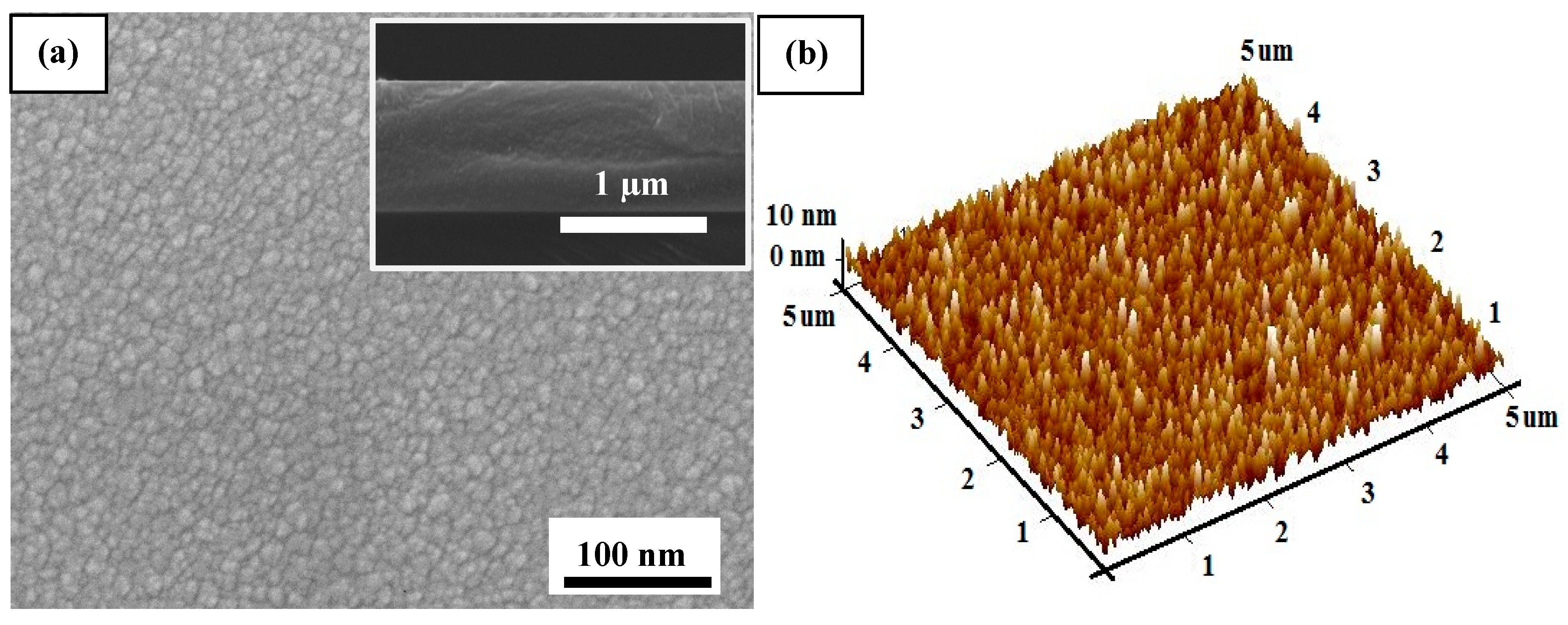
3.1. Structural and Surface Morphological Characteristics

By Hall measurement of the p-Mg-GaN film on the SiO2/Si (100) substrate at RT, the hole’s concentration (Np) and carrier mobility (μ) were found to be Np = 4.32 × 1016 cm−3 and μ = 7.52 cm2·V−1·s−1, respectively. Using SEM, the thicknesses of both the electrodes and the SiO2 layer were found to be 250 and 70 nm, respectively.
Figure 2a shows the SEM surface morphologies of the p-GaN films sputtered on the SiO2/Si (100) substrate. With EDS analysis results, the ratio of [Mg]/([Ga] + [Mg]) was 10.2% for the p-GaN film. This indicated that the p-Mg-GaN film deposited at 400 °C with up to 10% Mg displayed continuous smoothness without cracks and pores. The inset shows a cross-sectional image, with a thickness of 1 µm for the p-GaN film. Figure 2b shows the surface topography of the as-deposited Mg-GaN films on the SiO2/Si (100) substrate tested by AFM measurement. The surface topography showed smoother and smaller grains and the root-mean-square (rms) roughness of the films was found to be 3.27 nm. The EDS compositions, SEM surface morphologies and XRD patterns of the p-Mg-GaN film obtained with cermet targets at different Mg contents can be found in our previous works [20,21]. The positive surface conditions of Mg-GaN layer together with the insulator SiO2 layer were the important factors for determining the electrical properties of the MOS Schottky diodes.

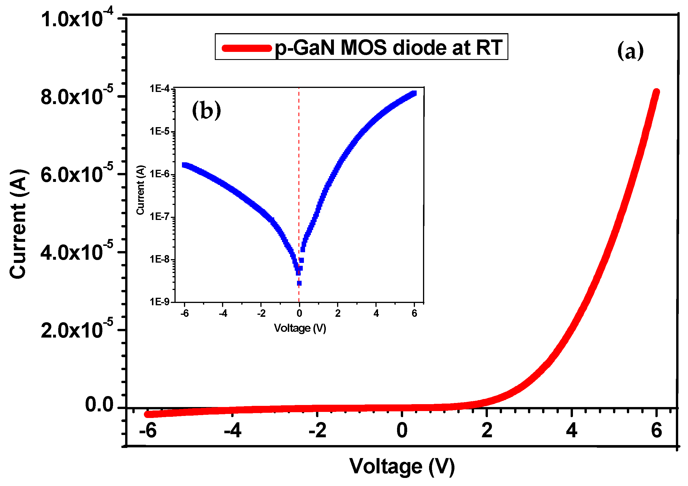
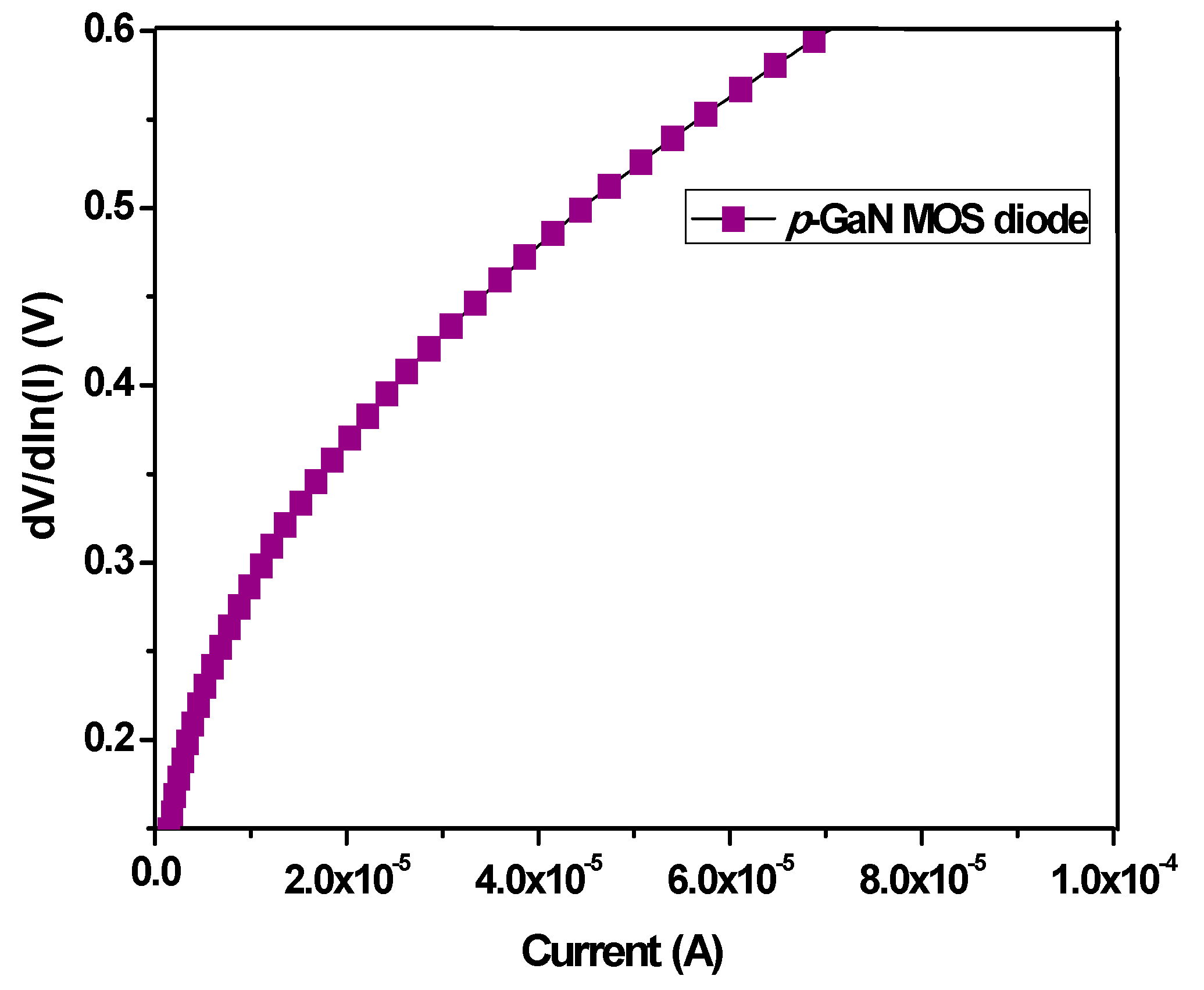
3.2. Current–Voltage (I–V) Characteristics

Figure 3a displays the IV plot of the Al/SiO2/p-GaN MOS Schottky diode measured at RT. The Figure 3b shows the lnIV semilogarithmic view of the diode. From the IV data, tested with a voltage range of (−6 V; +6 V) and a leakage current of −1 V, the turn-on voltage of the diode was determined to be ~4.49 × 10⁻⁶ A/cm2 and 2.3 V.
According to the thermionic emission (TE) mode (for qV > 3 kT), the electrical properties of the Schottky diode can be described as [6,11,22]:
I = I 0 exp [ q ( V I R s ) / n k T ]
The SBH can be expressed by [1,5,21]:
ϕ B = k T q ln ( A A * T 2 I 0 )
where I0 is the saturation current, V is the applied voltage, Rs is the series resistance, n is the ideality factor, T is the measured temperature in Kelvin, q is the electronic charge, k is the Boltzmann constant, ϕ B is the Schottky barrier height (SBH), A* is the Richardson constant, A is the contact area of the diode, and A* is the effective. The saturation current I0 was defined by the intersection between the interpolated straight lines of the linear region and the current axis.
Using a stainless-steel mask with a square opening, the electrodes of our diode were measured at 1 mm2. The A* value was 26.4 A·cm−2·K−2 (based on effective mass m* = 0.22 × me for GaN, me is electron mass) [4,5,13]. The ideality factor (n) from Equation (1) can be determined by [5,21,23]:
n = q k T ( d V d ( ln I ) )
Based upon Equations (1) and (2), the SBH of the diode was 0.67 V, while the ideality factor n, based on Equation (3), was 3.32. According to Cheung’s method, the series resistance Rs and ideality factor can be found by the intersecting slope from the linear region of the dV/d(lnI) vs. the I plots [11,22,24,25,26]:
d V d ( ln I ) = n k T q + I R S
As shown in Figure 4, a calculation based on Equation (4) showed that the values of Rs and n were 5914 Ω and 3.51, respectively. Our MOS Schottky diode had high series resistance because there was an insulator SiO2 layer of 70 nm between the metal and semiconductor.
The Norde method was also used to calculate the effective SBH of the diodes. The Norde function is described as the F(V, I) vs. the voltage V. It is given by [6,27]:
F ( V , I ) = V γ k T q ln ( I A A * T 2 )
The effective SBH ϕ B is obtained by:
ϕ B = F ( V min ) + V min γ k T q
where γ is the first integer (dimensionless) is higher than n, F(Vmin) is the min value of F(V), and Vmin is the corresponding voltage [27,28].
Figure 5 displays the plot of F(V) vs. the V of the Al/SiO2/p-GaN MOS Schottky diode measured at RT. Based on Equations (5) and (6), the SBH value was 0.78 eV for the device. Table 1 lists all the parameters of the diode, calculated by IV test, and Cheung’s and Norde’s methods.

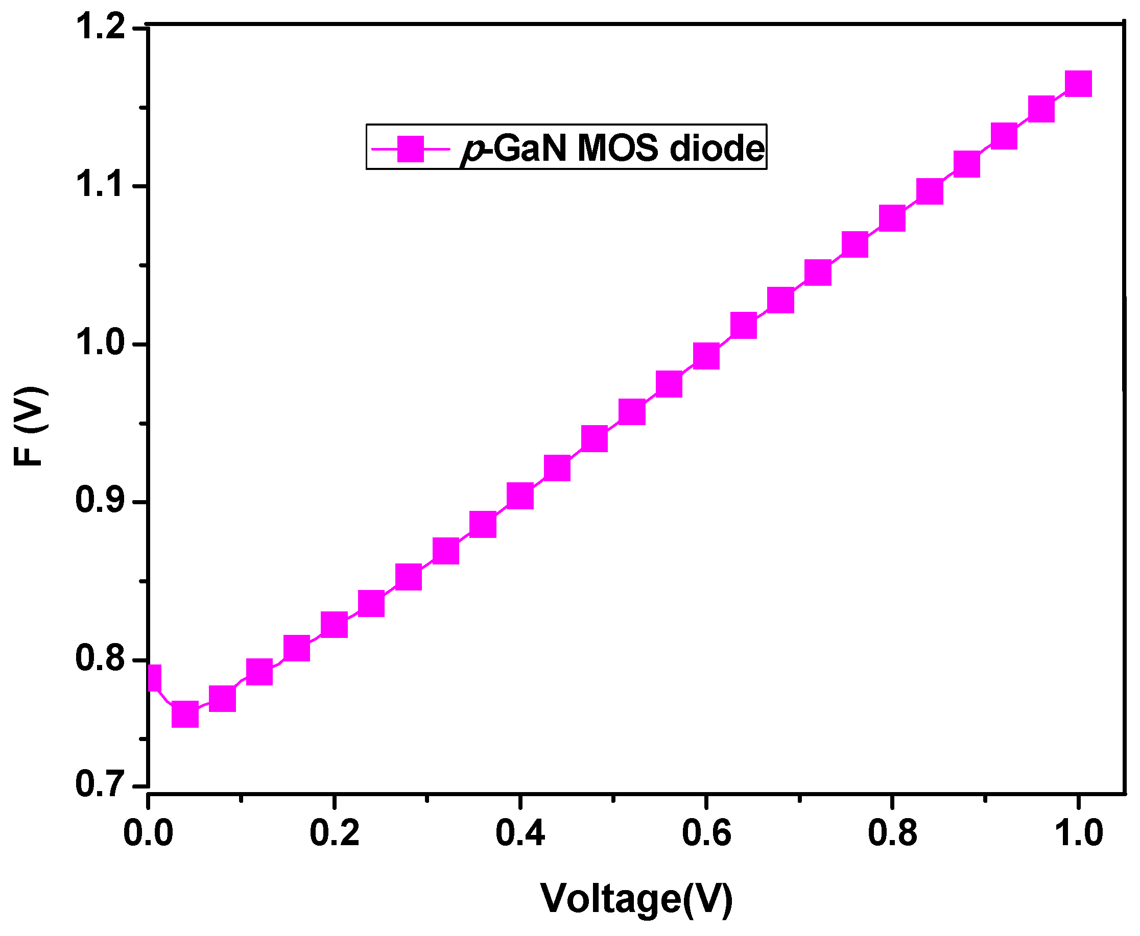
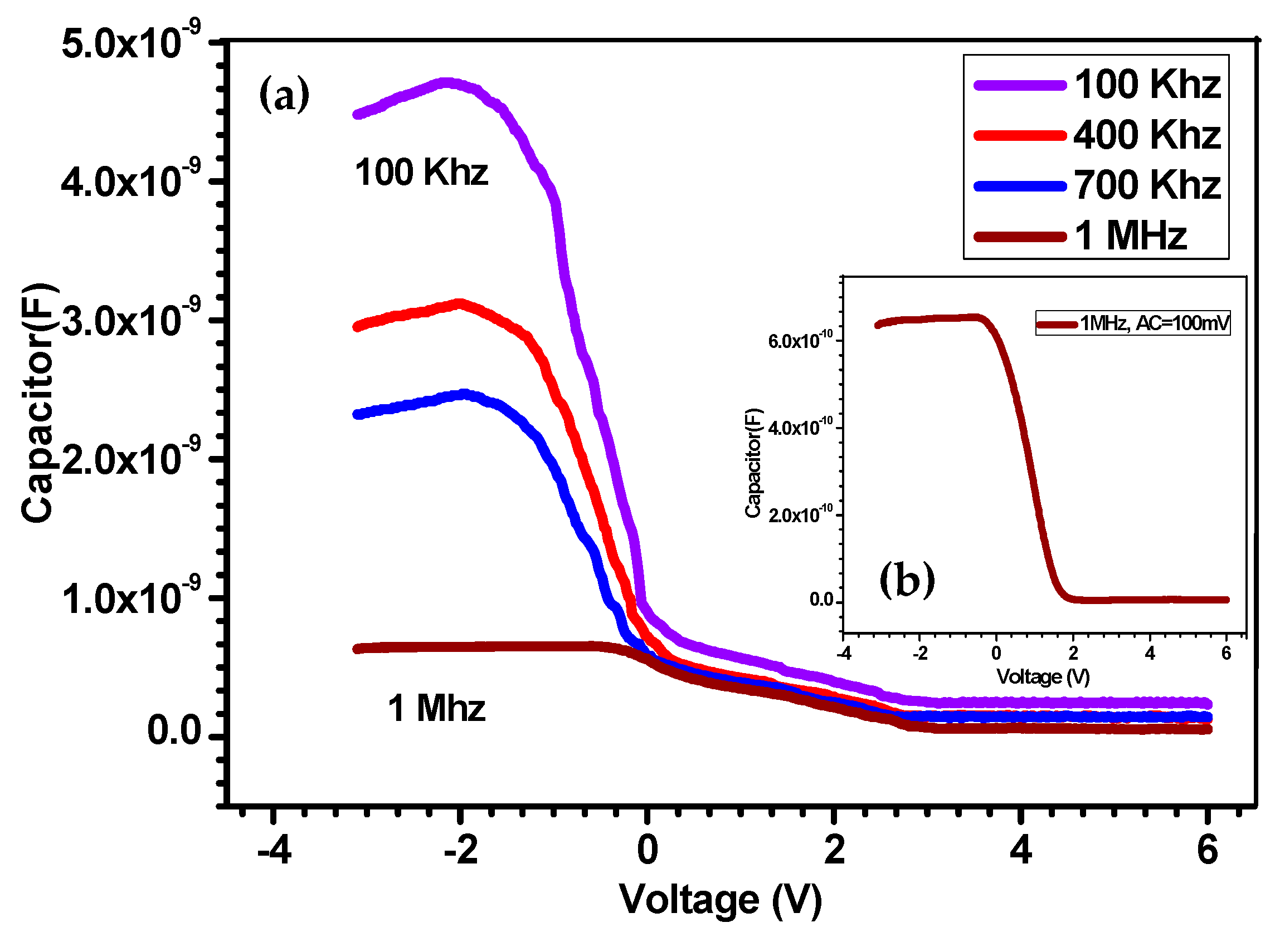
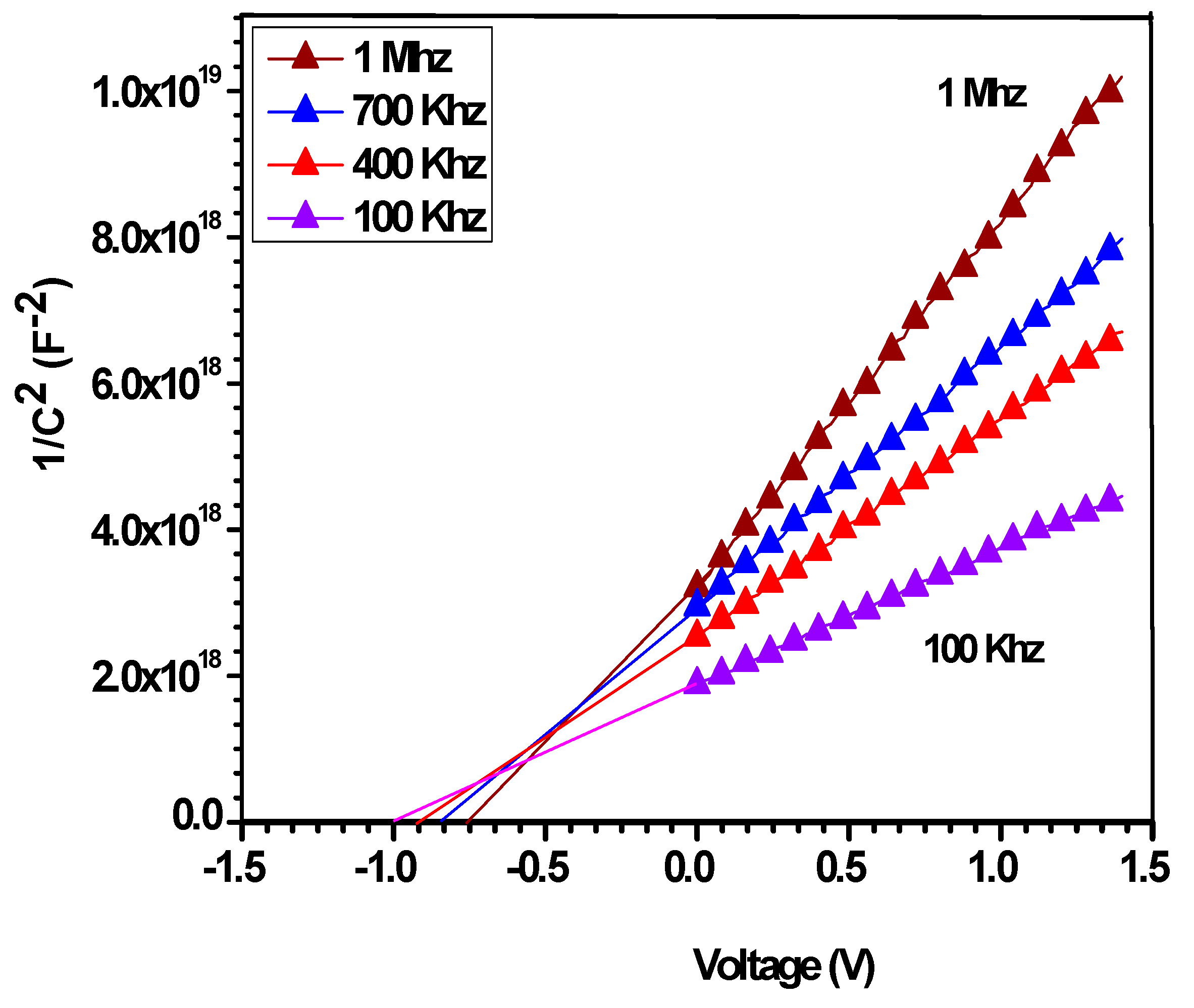
3.3. Capacitance–Voltage (C–V) Characteristics

The capacitance–voltage (CV) measurement of our diode was expressed and tested at room temperature, with a frequency range of 100 kHz–1 MHz. The CV relationship of diodes can be expressed by [4,9,13]:
1 C 2 = 2 ( V b i k T q V ) q ε s N p A 2
N p = 2 q ε s A 2   [ 1 d ( 1 / C 2 ) / d V ]
where Np is hole concentration, V is the flat band voltage, A is the area of the diode, and εs is the permittivity of the semiconductor (εs = 9.5 × εo for GaN, εo is electric constant) [4,13]. V0 is determined by the plot of 1/C2 vs. V. The potential Vbi is calculated from V0 by [4,5,11]:
V b i = V 0 + k T q
The SBH ϕ CV from the CV measurement is given by [13,14,18]:
ϕ CV = V b i + E F Δ Φ b
where EF is the energy of Fermi level. This is given by [9,11,13]:
E F = k T q ln ( N c N p )
Based on the m* = 0.22 × me for GaN, Nc is the density of states in the conduction band edge. It is expressed by [2,5,7]:
N c = 2 ( 2 π m * k T h 2 ) 3 / 2
where h is Plank constant. The Δ Φ b is the image force-induced barrier lowering. It is given by [7,9,13]:
Δ Φ b = [ q E m 4 π ε s ε 0 ] 1 / 2
where Em is the maximum electric field and given by [9,13]:
E m = [ 2 q N p V 0 ε s ε 0 ] 1 / 2
Figure 6a shows the plotted CV measurement of the MOS Schottky diode tested at the frequency range 100 KHz–1 MHz. The Figure 6b is the electrical properties of the diode, which was measured at a frequency of 1 MHz with an alternating current (AC) modulation of 100 mV. Figure 7 shows the characterization of 1/C2 vs. V as a function of the p-MOS Schottky diode tested at different frequencies. The x-intercept of the 1/C2 vs. V plot determined V0 from the straight lines for the downward region at the reverse bias [4,5,7,11].
Based on Equation (8), the hole concentration of the diode increased from 3.92 × 1016 cm−3 to 5.36 × 1016 cm−3 tested at 100 KHz to 1 MHz, while the Fermi level of the diode slightly decreased from 0.109 to 0.099 eV. After calculating the values of V0, Vbi, EF, Em, and Δ Φ b , based on Equations (9)–(14), the values of V0 and the SBH values were reduced from 0.99 to 0.75 eV and 1.06 to 0.88 eV, respectively, when the testing frequencies were changed from 100 kHz to 1 MHz (Table 2).

4. Discussion

Table 1 and Table 2 display all the parameters of the MOS Schottky diode measured by IV and CV measurements. This MOS Schottky diode showed an acceptable leakage current of ~4.49 × 10⁸ A at −1 V, a breakdown voltage of −6 V, and a turn-on voltage of ~2.1 V. Calculating using Cheung’s method, the MOS Schottky had Rs of 5918 Ω and n of 3.51. In addition, from the plot of the IV curve, the ideality factor n was found to be 3.32. This indicated that a higher turn-on voltage leads to a higher ideality factor [4,9,13]. The growth of an insulator SiO2 layer can effect to the accumulation layer during the forward bias, which affected to the high value of Rs in our Schotky diode. For similar results, by measurement at RT, the series resistance (Rs) and ideality factor (n) were calculated to be 84.4 kΩ and 2.96 for the Pt/SiO2/n-GaN MOS Schottky diode [6], 230 Ω and 1.6 for the Au/SiO2/n-GaN MOS diode [13], and 66 Ω and 2.48 for the Al/SnO2/p-Si (111) MOS diode, respectively [18].
From Table 2, we showed that the CV measurement data depended strongly on the tested frequency at the RT. At the high frequency (1 MHz), the interface state density could not identify the value of capacitance because it balanced with the semiconductor. At the low frequency, the interface state’s density easily followed the AC signal. This created a signal and extra capacitance [11,13,18]. The Np and SBH decreased from 5.36 × 1016 cm3 to 3.92 × 1016 cm3 and from 1.06 to 0.88 eV, respectively, with increased frequency, due to the existence of the interfacial SiO2 layer in the depletion region. Similarly, the Np of our Schottky diode was 5.36 × 1016 cm−3 when tested at a frequency of 1 MHz at RT [7]. The Np and SBH of the Au/SiO2/n-GaN MOS diode were 2.08 × 1017 cm−3 and 0.99 eV, also tested at a frequency of 1 MHz [9].
The hole’s concentration (Np), calculated from the 1/C2V plots for the MOS Schottky diode, was lower than that calculated by the Hall measurement because this result was measured from the p-Mg-GaN film deposited on the SiO2/Si substrate. In addition, with the fast growth rate in deposition, the interface between p-GaN and SiO2 affected the polarized SiO2 layer. The electrical field across the depletion region changed significantly near the p-GaN layer. It was affected by the strong variation in the hole’s concentration, leakage current, and turn-on and breakdown voltages of the diode [11,15,16].
Therefore, the SBH of our MOS Schottky diode, in terms of CV measurement, was higher than the IV test because of the charges induced by dielectric layer. The SBH of our diode corresponded with some results (0.67–1.06 eV) of the GaN Schottky diodes made by metal organic chemical vapor deposition (MOCVD) and other approaches. Cheng et al. also reported the SBH of a Pt-oxide-Al0.3Ga0.7As MOS diode, which decreased from 1.03 to 0.86 eV after annealing in a hydrogen atmosphere [16]. Baris et al. reported all the parameters of Au/TiO/n-Si (100) MOS diodes; an ideality factor of 3.72 and an SBH of 0.62 eV were determined by testing the IV measurement. Meanwhile, via calculation by CV measurement, the SBH and bulk concentration were determined to be 0.99 eV and 9.82 × 1014 cm−3, respectively [23].

5. Conclusions

The modeling and electrical properties of the Al/SiO2/p-GaN MOS Schottky diode were successfully established by total RF sputtering. All the parameters were calculated based on IV and CV measurements. The SBHs of the MOS Schottky diodes were determined to be 0.67 (IV), 0.78 eV (Norde), and 0.88 eV (CV). The hole’s concentration, tested by CV measurement, decreased slightly compared with that determined by the Hall measurement. This was due to the existence of the SiO2 layer in the p-GaN MOS diode. Our work using cost-effective RF sputtering to make the Al/SiO2/p-GaN MOS Schottky diode can be applied to the development of electronic devices.

Author Contributions

Data curation, P.T.C. and T.A.T.T.; methodology, writing—original draft, investigation, P.T.C. and T.A.T.T., formal analysis, funding acquisition, writing—review and editing, P.T.C., T.A.T.T., P.Q.-P., V.K.N. and N.P.L.T.; supervision, D.-H.K.

Funding

This research was funded by the Ministry of Science and Technology of the Republic of China under grant number 107-2221-E-011-141-MY3.

Conflicts of Interest

The authors declare no conflict of interest.

References

  1. Arslan, E.; Bütüna, S.; Safak, Y.; Özbaya, E.; Uslu, H. Electrical characterization of MS and MIS structures on AlGaN/AlN/GaN heterostructures. Microelectron. Reliab. 2011, 51, 370–375. [Google Scholar] [CrossRef]
  2. Chang, P.C.; Yu, C.L.; Chiu, Y.J.; Liu, C.H.; Chang, S.J.; Su, Y.K.; Chuang, R.W. Ir/Pt Schottky contact oxidation for nitride-based Schottky barrier diodes. Phys. Status Solidi C 2007, 5, 1625–1628. [Google Scholar] [CrossRef]
  3. Li, C.C.; Kuo, D.H. Effects of growth temperature on electrical and structural properties of sputtered GaN films with a cermet target. J. Mater. Sci. Mater. Electron. 2014, 25, 1404–1409. [Google Scholar] [CrossRef]
  4. Reddy, M.S.; Reddy, V.R.; Choi, C.J. Electrical properties and interfacial reactions of rapidly annealed Ni/Ru Schottky rectifiers on n-type GaN. J. Alloys. Comp. 2010, 503, 186–191. [Google Scholar] [CrossRef]
  5. Reddy, R.; Rao, P.K. ;Annealing temperature effect on electrical and structural properties of Cu/Au Schottky contacts to n-type GaN. Microelectron. Eng. 2008, 85, 470–476. [Google Scholar] [CrossRef]
  6. Tuan, T.T.A.; Kuo, D.H.; Li, C.C.; Yen, W.C. Schottky barrier characteristics of Pt contacts to all sputtering-made n-type GaN and MOS diodes. J. Mater. Sci. Mater. Electron. 2014, 25, 3264–3270. [Google Scholar] [CrossRef]
  7. Bengi, S.; Bülbül, M.M. Electrical and dielectric properties of Al/HfO2/p-Si MOS device at high temperatures. Curr. Appl. Phys. 2013, 25, 1819–1825. [Google Scholar] [CrossRef]
  8. Tsevas, S.; Vasilopoulou, M.; Kouvatsos, D.N.; Speliotis, T.; Niarchos, D. Characteristics of MOS diodes fabricated using sputter-deposited W or Cu/W film. Microelectron. Eng. 2006, 83, 1434–1437. [Google Scholar] [CrossRef]
  9. Reddy, V.R.; Reddy, M.S.; Lakshmi, B.P.; Kumar, A. Electrical characterization of Au/n-GaN metal-semiconductor and Au/SiO2/n-GaN metal-insulator-semiconductor structures. J. Alloys. Comp. 2011, 509, 8001–8007. [Google Scholar] [CrossRef]
  10. Lin, K.W.; Chen, H.; Cheng, C.C.; Chuang, H.-M.; Lu, C.T.; Liu, W.C. Characteristics of a new Pt/oxide/In0.49Ga0.51P hydrogen-sensing Schottky diode. Sens. Act. B 2003, 94, 145–151. [Google Scholar] [CrossRef]
  11. Tuan, T.T.A.; Kuo, D.H. Characteristics of RF reactive sputter-deposited Pt/SiO2/n-InGaN MOS Schottky diodes. Mater. Sci. Semicond. Process. 2015, 30, 314–320. [Google Scholar] [CrossRef]
  12. Liu, I.P.; Chang, C.H.; Huang, J.; Lin, K.W. Hydrogen sensing characteristics of a Pd/Nickel oxide/GaN-based Schottky diode. Int. J. Hydrogen Energy 2019, 44, 5748–5754. [Google Scholar] [CrossRef]
  13. Lakshmi, B.P.; Reddy, M.S.; Kumar, A.A.; Reddy, V.R. Electrical transport properties of Au/SiO2/n-GaN MIS structure in a wide temperature range. Curr. Appl. Phys. 2012, 12, 765–772. [Google Scholar] [CrossRef]
  14. Juang, F.R.; Fang, Y.K.; Chiu, H.Y. Dependence of the Au/SnOx/n-LTPS/glass thin film MOS Schottky diode CO gas sensing performances on operating temperature. Microelectron. Reliab. 2012, 32, 160–165. [Google Scholar] [CrossRef]
  15. Tsai, T.H.; Huang, J.R.; Lin, K.W.; Hsu, W.C.; Chen, H.I.; Liu, W.C. Improved hydrogen sensing characteristics of a Pt/SiO2/GaN Schottky diode. Sens. Act. B 2008, 129, 292–302. [Google Scholar] [CrossRef]
  16. Cheng, C.C.; Tsai, Y.Y.; Lin, K.W.; Chen, H.I.; Lu, C.T.; Liu, W.C. Hydrogen sensing characteristics of a Pt-oxide-Al0.3Ga0.7As MOS Schottky diode. Sens. Act. B 2004, 99, 292–302. [Google Scholar] [CrossRef]
  17. Chen, H.I.; Chang, C.C.; Lu, H.H.; Liu, I.-P.; Chen, W.C.; Ke, B.Y.; Liu, W.C. Hydrogen sensing performance of a Pd/HfO2/GaN metal-oxide-semiconductor (MOS) Schottky diode. Sens. Act B 2018, 262, 852–859. [Google Scholar] [CrossRef]
  18. Karadeniz, S.; Tuğluoğlu, N.; Serin, T. Substrate temperature dependence of series resistance in Al/SnO2/p-Si (111) Schottky diodes prepared by spray deposition method. Appl. Surf. Sci. 2004, 233, 5–13. [Google Scholar] [CrossRef]
  19. Chang, C.F.; STai, T.H.; Chen, H.I.; Lin, K.W.; Chen, T.P.; Chen, L.Y.; Liu, Y.C.; Liu, W.C. Hydrogen sensing properties of a Pd/SiO2/AlGaN-based MOS diode. Electrochem. Communi. 2009, 11, 65–67. [Google Scholar] [CrossRef]
  20. Li, C.C.; Kuo, D.H. Material and technology developments of the totally sputtering-made p-n GaN diodes for cost-effective power electronics. J. Mater. Sci. Mater. Electron. 2014, 25, 1942–1948. [Google Scholar] [CrossRef]
  21. Tuan, T.T.A.; Kuo, D.H.; Li, C.C.; Li, G.Z. Effect of temperature dependence on electrical characterization of p-n GaN diode fabricated by RF magnetron sputtering. Mater. Sci. Appl. 2015, 6, 809–817. [Google Scholar]
  22. Ramesh, C.K.; Reddy, V.R.; Choi, C.J. Electrical characteristics of molybdenum Schottky contacts on n-type GaN. Mater. Sci. Eng. B 2004, 112, 30–33. [Google Scholar] [CrossRef]
  23. Barış, B. Analysis of device parameters for Au/TiO2/n-Si (100) metal-oxide semiconductor (MOS) diodes. Phys. B 2014, 438, 65–69. [Google Scholar] [CrossRef]
  24. Cheung, S.K.; Cheung, N.W. Extraction of Schottky diode parameters from forward current-voltage characteristics. Appl. Phys. Lett. 1986, 49, 85–87. [Google Scholar] [CrossRef]
  25. Tuan, T.T.A.; Kuo, D.H.; Saragih, A.D.; Li, G.Z. Electrical properties of RF-sputtered Zn-doped GaN films and p-Zn-GaN/n-Si hetero junction diode with low leakage current of 109A and a high rectification ratio above 105. Mater. Sci. Eng. B 2017, 222, 18–25. [Google Scholar] [CrossRef]
  26. Ravinandan, M.; Rao, P.K.; Reddy, V.R. Temperature dependence of current-voltage IV characteristics of Pt/Au Schottky contacts on n-type GaN. J. Optoelectron. Adv. Mater. 2008, 10, 2787–2792. [Google Scholar]
  27. Norde, H. A modified forward IV plot for Schottky diodes with high series resistance. J. Appl. Phys. 1979, 50, 5052–5053. [Google Scholar] [CrossRef]
  28. Tuan, T.T.A.; Kuo, D.H. Temperature-dependent electrical propertiesof the sputtering-made n-InGaN/p-GaN junction diode with a breakdown voltage above 20 V. Mater. Sci. Semicond. Process. 2015, 32, 160–165. [Google Scholar] [CrossRef]
Figure 1. The modeling of the as-deposited Al/SiO2/p-GaN MOS Schottky diode.
Coatings 09 00685 g001
Figure 2. (a) SEM surface image and (b) three-dimensional AFM topographies of the p-GaN film deposited on the SiO2/Si (100) substrate. The inset is the cross-sectional image of the p-GaN film.
Coatings 09 00685 g002
Figure 3. (a) IV plot of the as-deposited Al/SiO2/p-GaN MOS Schottky diode tested at RT, (b) the forward and reverse lnIV characteristics of diodes.
Coatings 09 00685 g003
Figure 4. Plot of dV/dln(I) versus I for the as-deposited Al/SiO2/p-GaN MOS Schottky diode.
Coatings 09 00685 g004
Figure 5. Characterization of the F(V, I) vs. V for the as-deposited Al/SiO2/p-GaN MOS Schottky diode.
Coatings 09 00685 g005
Figure 6. (a) Plot CV measurement for the as-deposited Al/SiO2/p-GaN MOS Schottky diode measurement at different frequencies between 100 kHz and 1 MHz, AC = 100 mV. (b) The electrical properties of the diode was measured at frequency of 1 MHz, AC = 100 mV.
Coatings 09 00685 g006
Figure 7. Plot of the 1/C−2V for the as-deposited Al/SiO2/p-GaN MOS Schottky diode measurement at different frequencies between 100 kHz and 1 MHz, AC = 100 mV.
Coatings 09 00685 g007
Table 1. The parameters of the IV characteristics of the Al/SiO2/p-MOS Schottky diode at room temperature.
SampleLeakage Current (A) at −1 (V)Schottky Barrier
Height (SBH) (eV)
From I–VCheungs’ Function
dV/dln(I)–I
IVNordenRs (Ω)n
As-dep.4.49 × 10−80.670.783.3259143.51
Table 2. The parameters calculated from 1/C2V for characteristics of the Al/SiO2/p-GaN MOS Schottky diode between 100 kHz and 1 MHz at the room temperature.
Frequency (KHz)Np (cm−3)EF (eV)V0 (eV) Δ Φ b   ( eV ) ϕ C V   ( eV )
10003.92 × 10160.1090.750.0390.88
7004.20 × 10160.1060.820.0420.94
4004.89 × 10160.1030.900.0441.02
1005.36 × 10160.0990.990.0461.06

