Effect of Carbon Fiber Addition on the Microstructure and Wear Resistance of Laser Cladding Composite Coatings

Abstract
:1. Introduction
2. Experimental Procedures
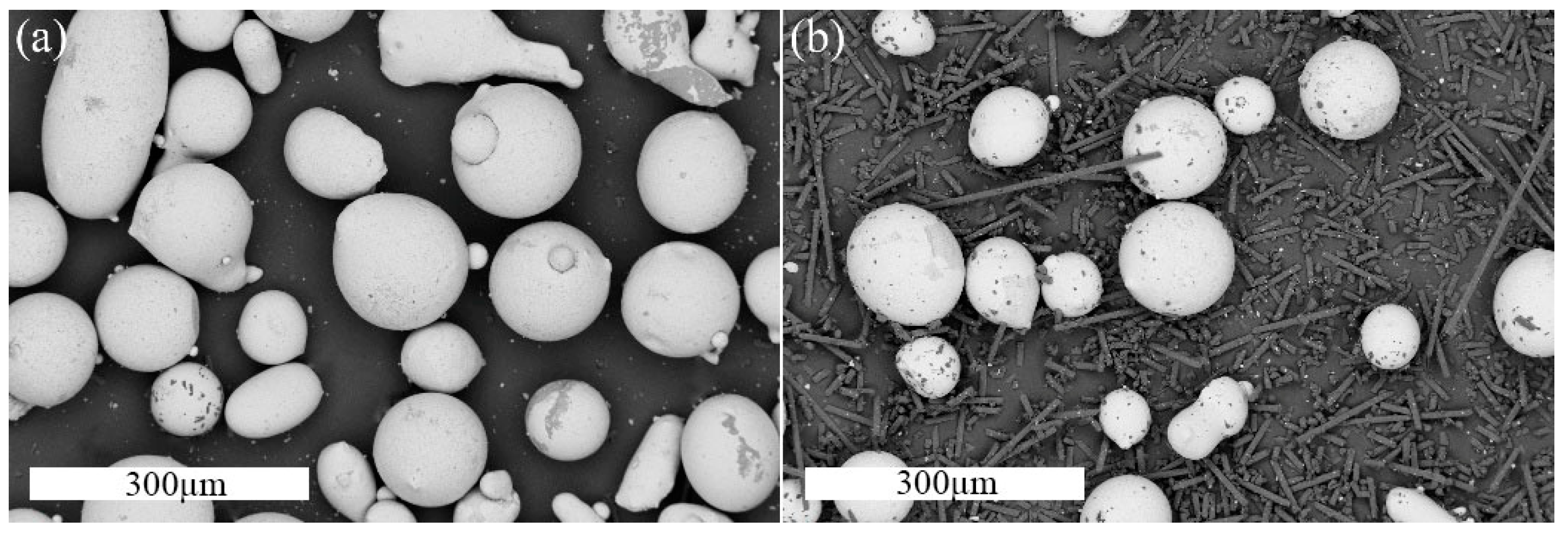
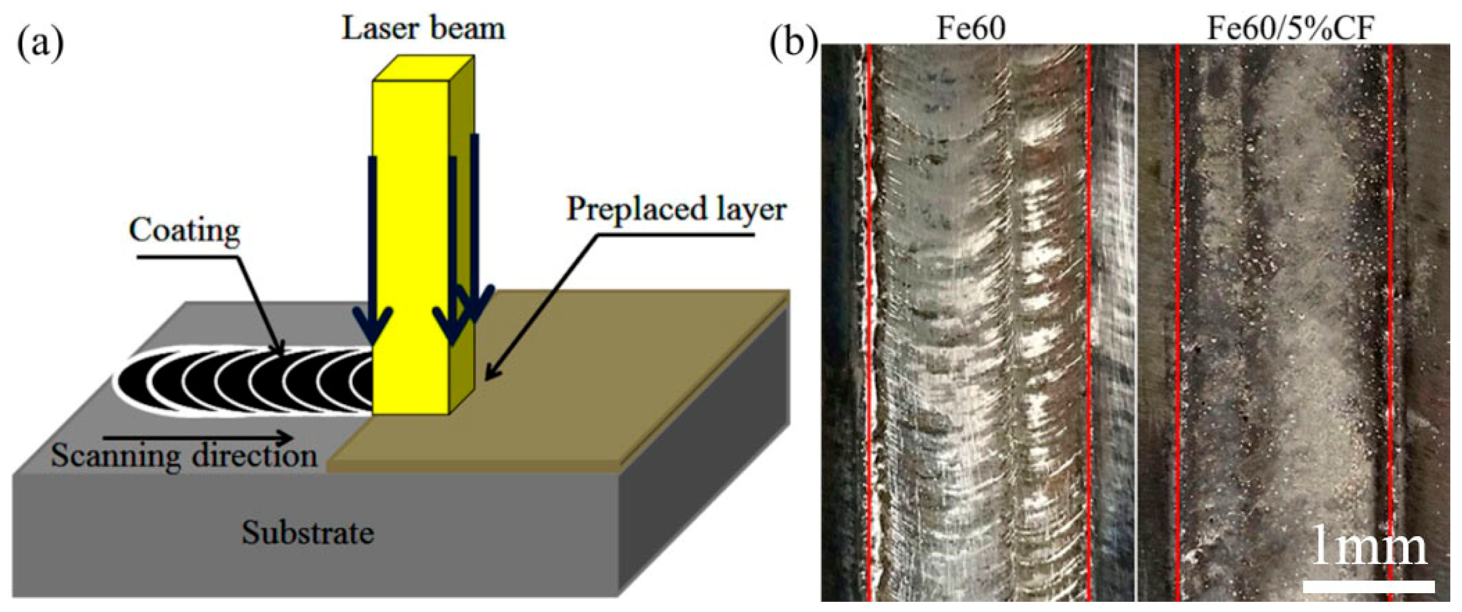
2.1. Preparation of Composite Coatings
2.2. Microstructure Characterization and Properties Measurements
3. Results and Discussion
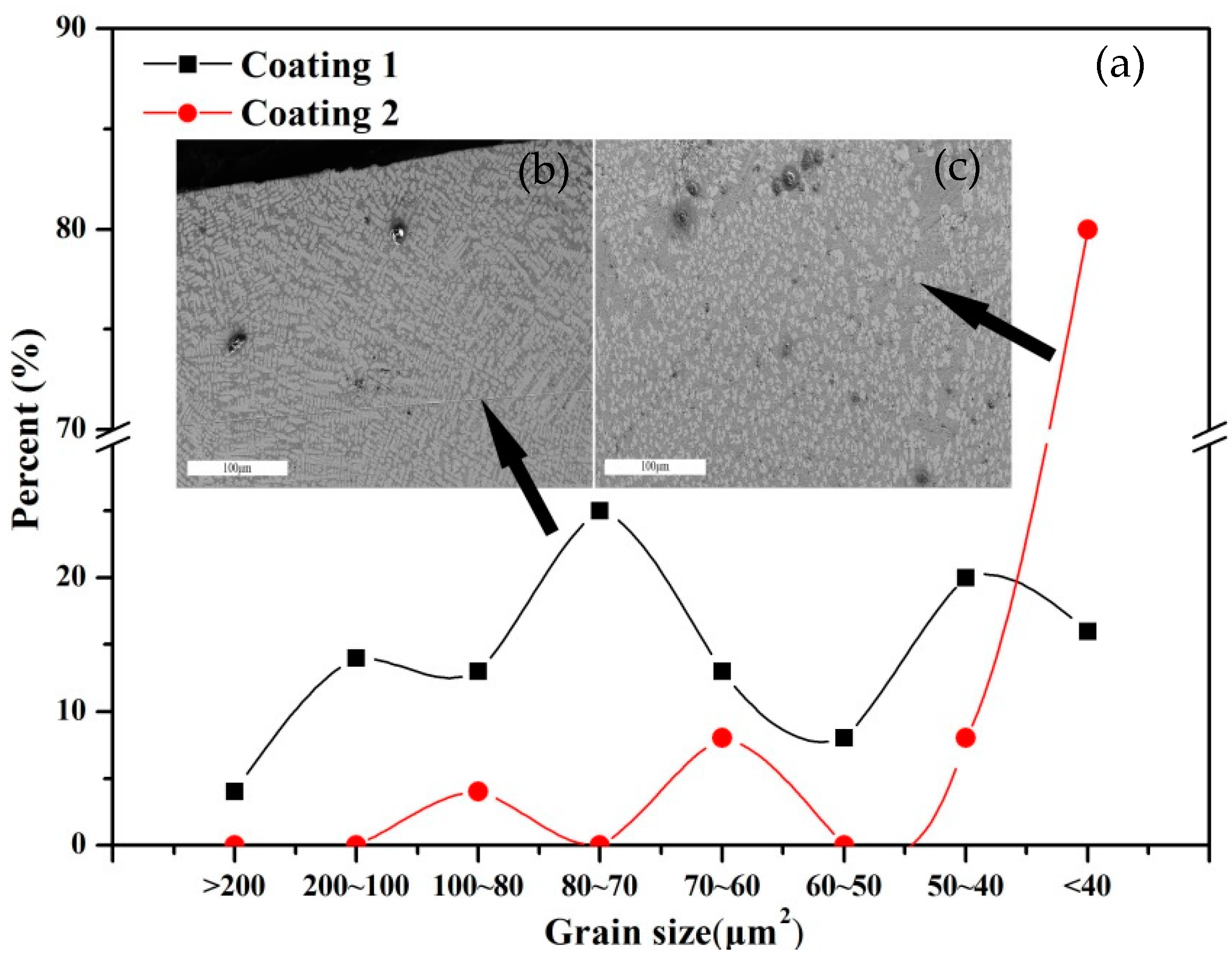
3.1. Macro Observation
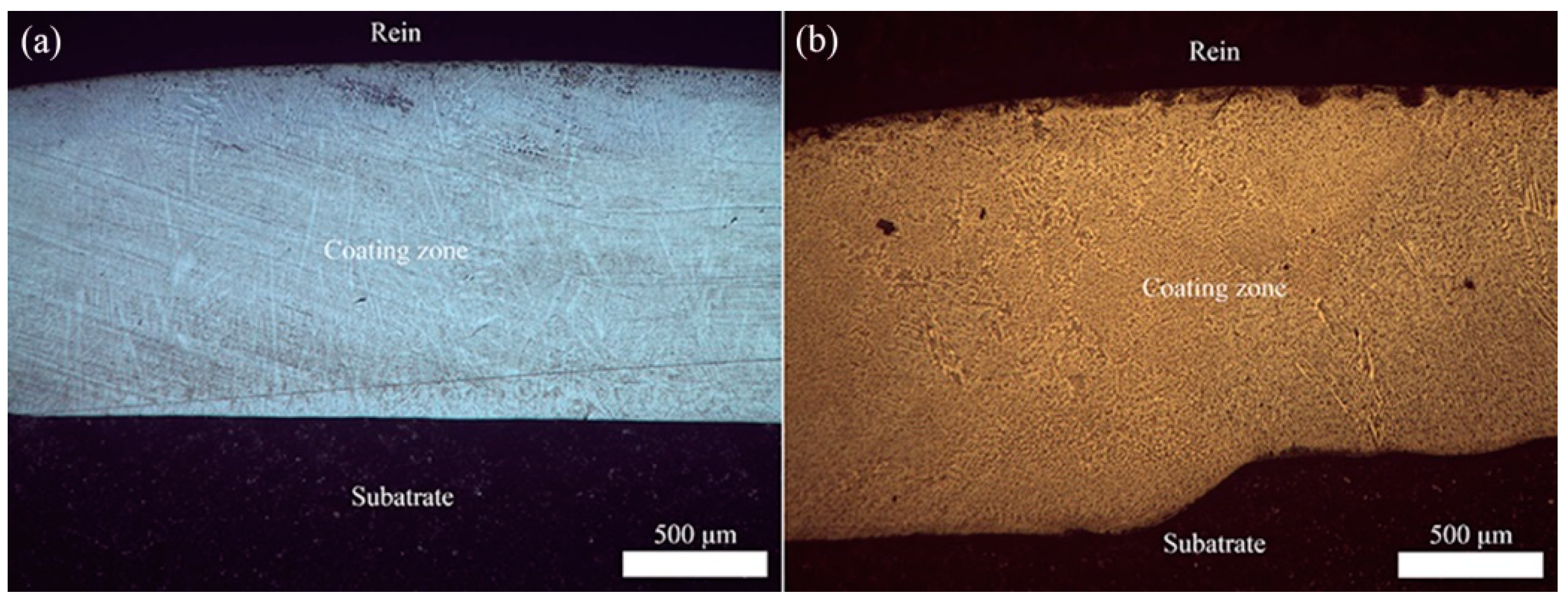
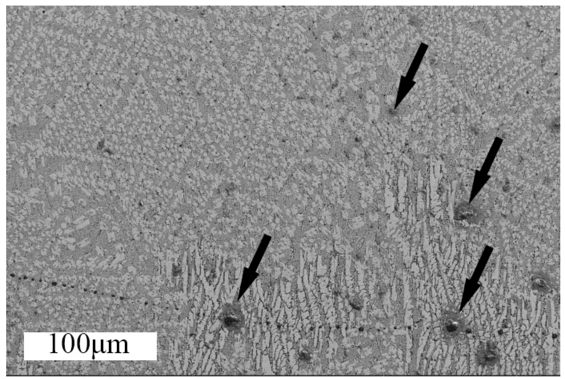
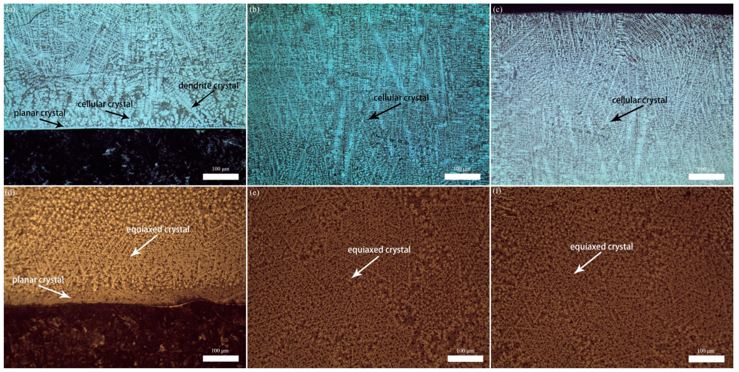
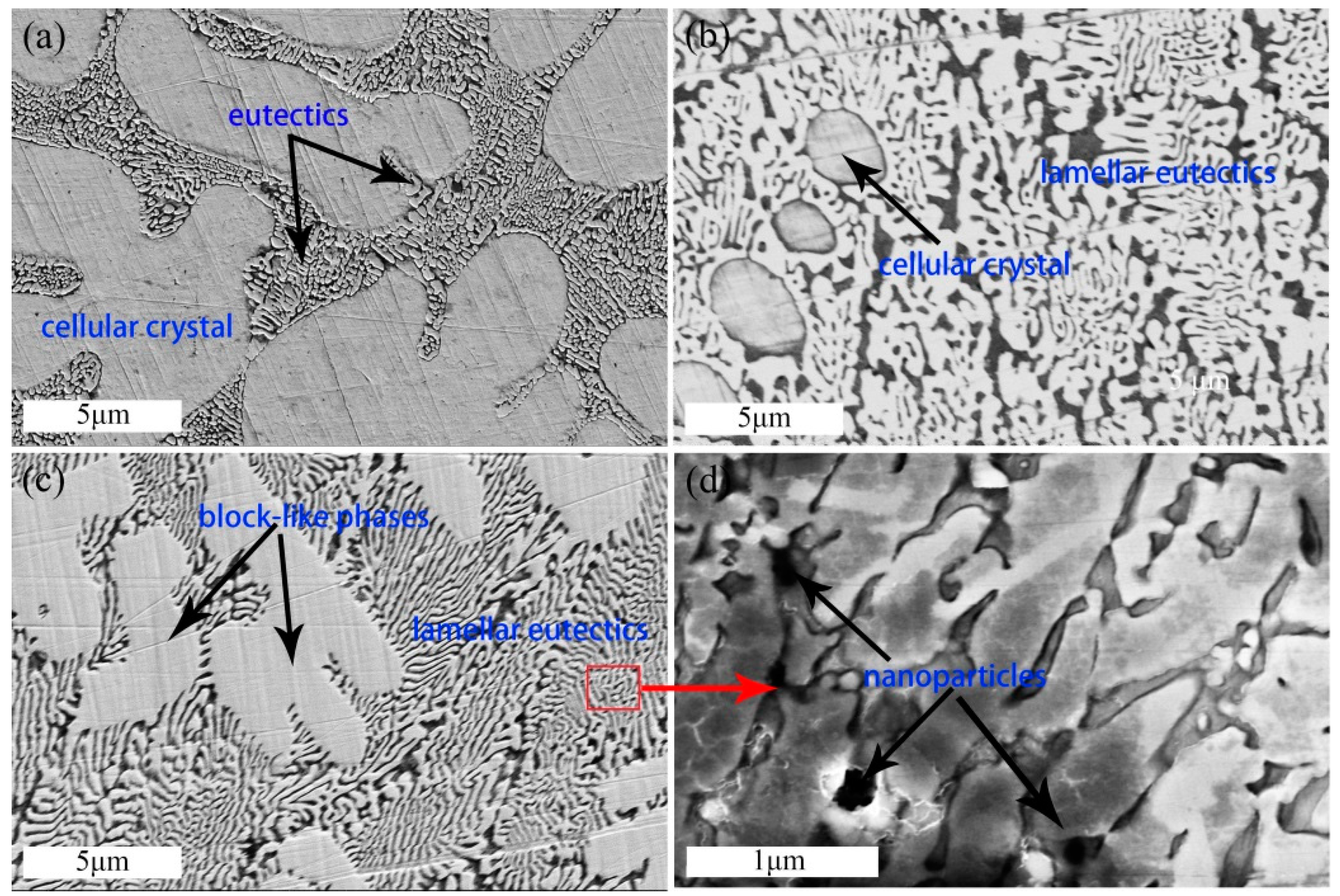
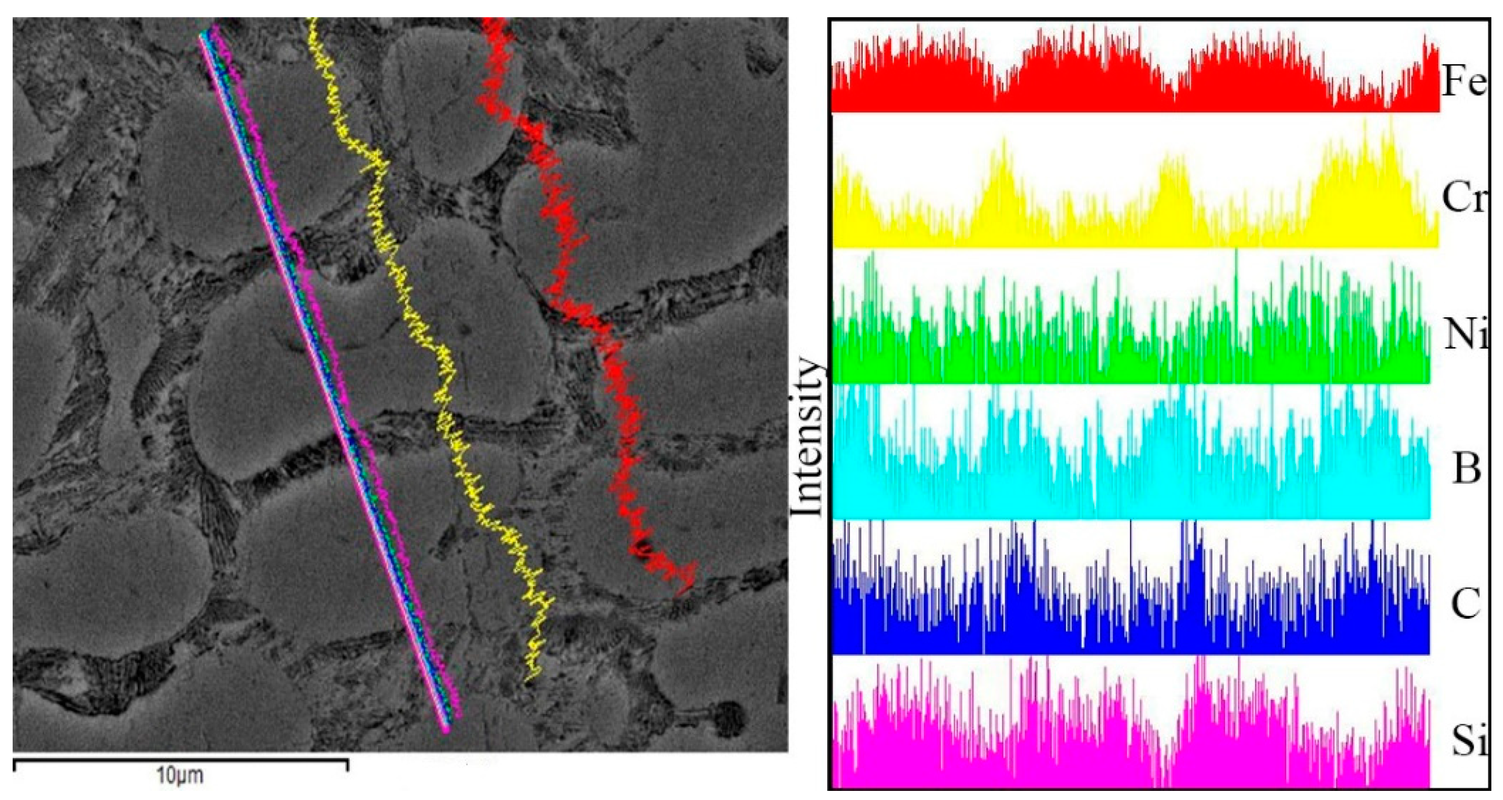
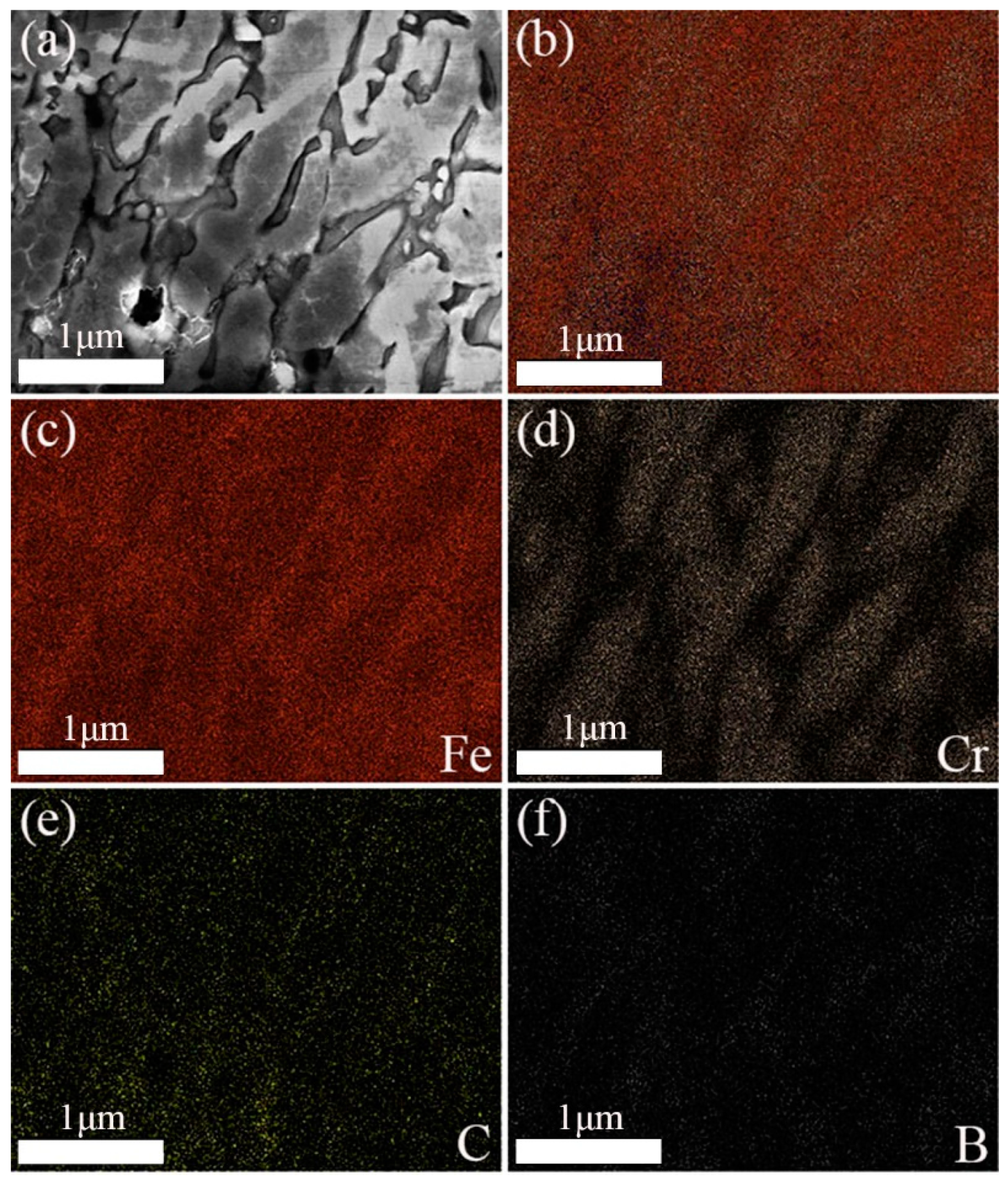
3.2. Microstructure
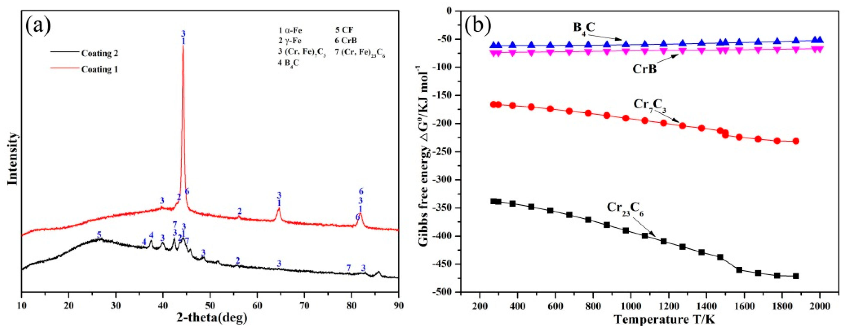
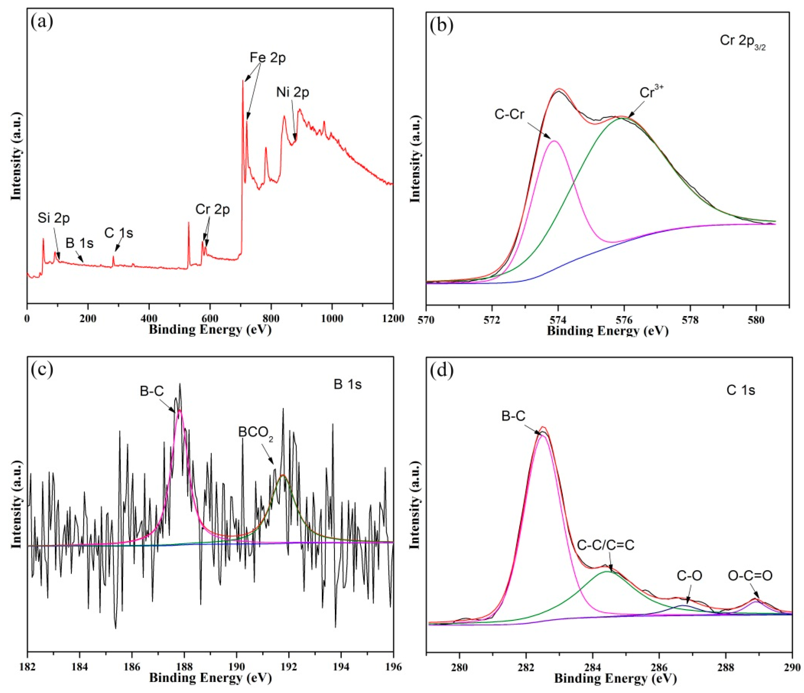
3.3. Phase Analysis
3.4. Microstructural Evolution of the Composite Coating with the Addition of CFs
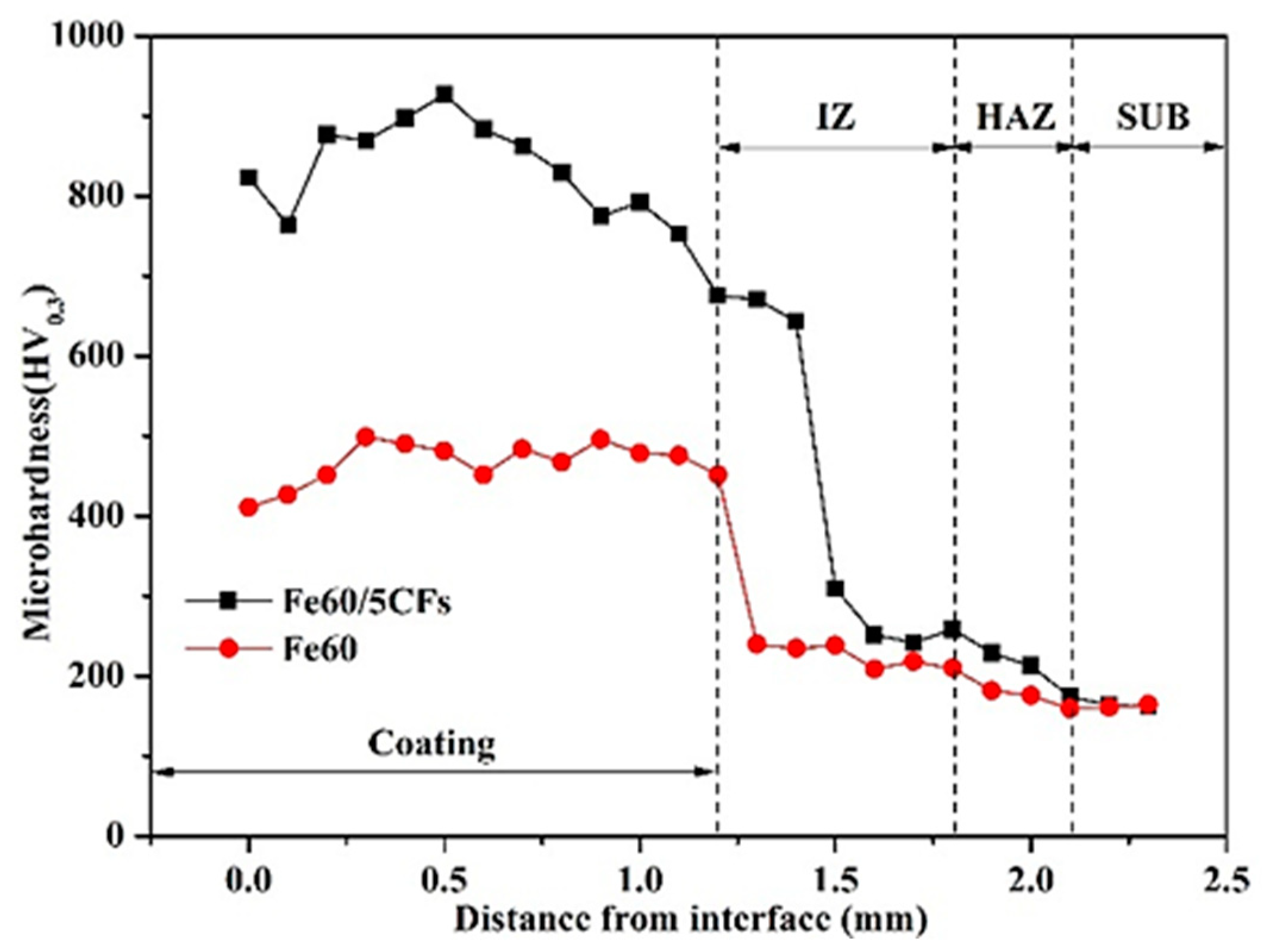
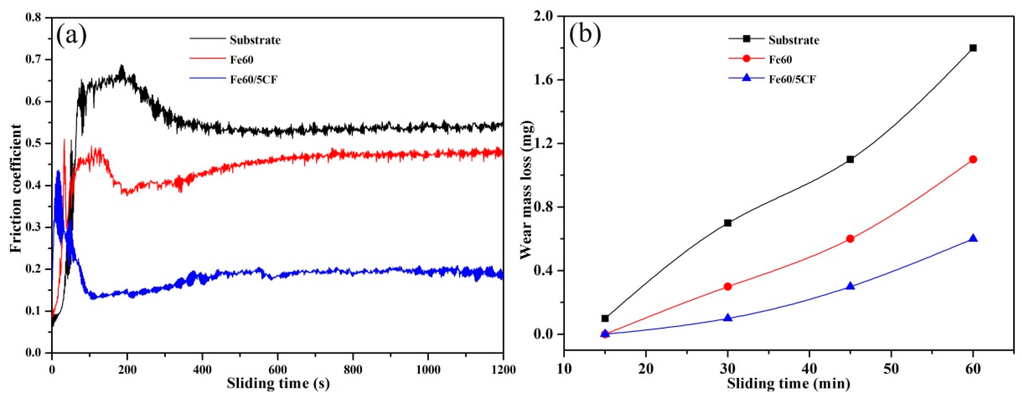
3.5. Microhardness and Wear Resistance
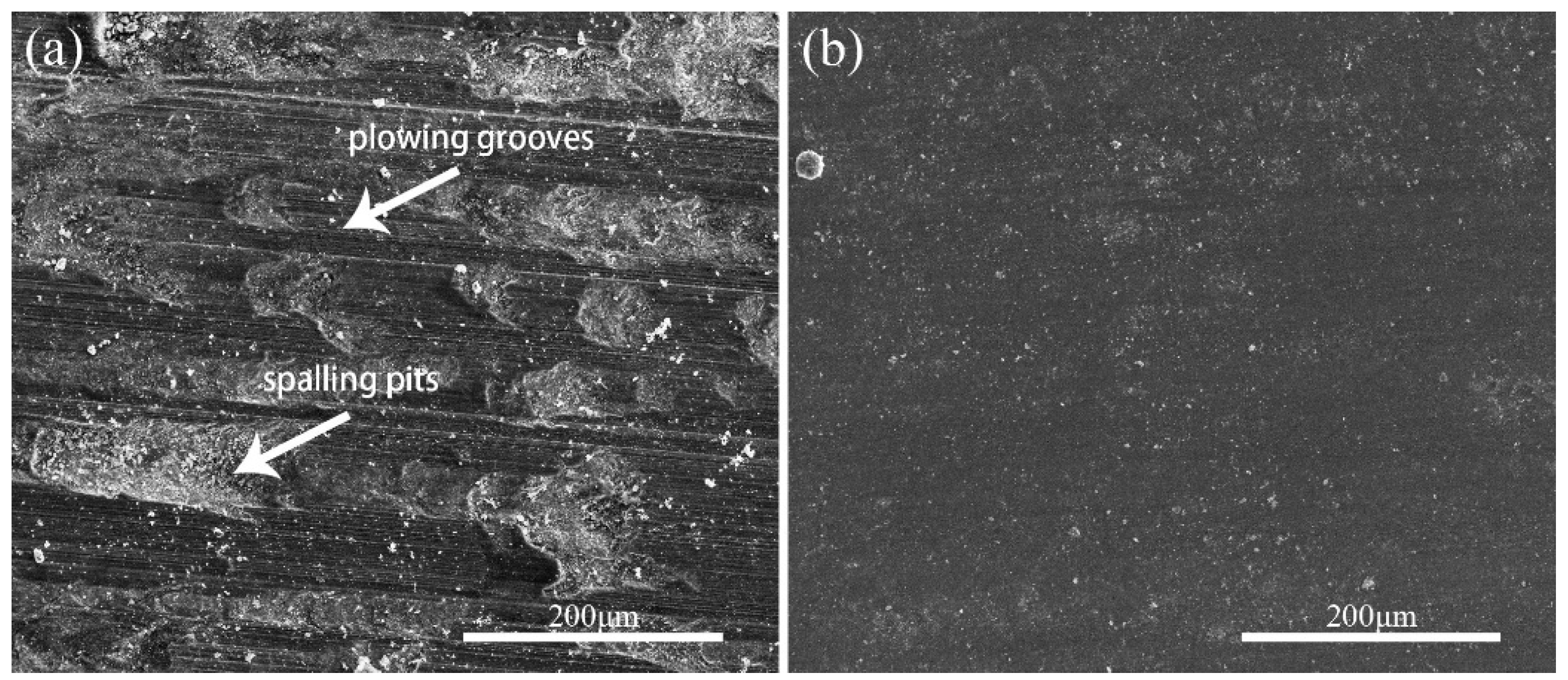
3.6. Wear Mechanism
4. Conclusions
- Compared with the original Fe-based alloy coating, (Cr, Fe)7C3 and nano-size B4C carbides were in-situ synthesized in the lamellar eutectics’ matrix. Moreover, the CFs were partly dissolved in the melt pool, and the remaining CFs in the composite coating could act as a lubricating phase which contributed to the wear resistance.
- The microhardness of the composite coating was greatly enhanced with the addition of CFs. The hardening mechanism was changed, which transformed from the solid-solution strengthening of supersaturated solid solutions to the dispersion strengthening of in-situ synthesized reinforcements.
- The wear resistance of the composite coating with the addition of CFs was improved by approximately two times compared with the original coating. Wear mechanisms for the composite coating were different. The original coating showed the dominant wear mechanisms of micro-cutting and serious brittle spalling, while the composite coating with CFs showed the main wear mechanism of slight scratching.
Author Contributions
Funding
Acknowledgments
Conflicts of Interest
References
- da Silva, L.J. NiCrSiBC coatings: Effect of dilution on microstructure and high temperature tribological behavior. Wear 2016, 350–351, 130–140. [Google Scholar] [CrossRef]
- Yang, M.S.; Liu, X.B.; Fan, J.W.; He, X.M.; Shi, S.H.; Fu, G.Y.; Wang, M.D.; Chen, S.F. Microstructure and wear behaviors of laser clad NiCr/Cr3C2-WS2 high temperature self-lubricating wear-resistant composite coating. Appl. Surf. Sci. 2012, 258, 3757–3762. [Google Scholar] [CrossRef]
- Liu, X.B.; Zheng, C.; Liu, Y.F.; Fan, J.W.; Yang, M.S.; He, X.M.; Wang, M.D.; Yang, H.B.; Qi, L.H. A comparative study of laser cladding high temperature wear-resistant composite coating with the addition of self-lubricating WS2 and WS2/(Ni–P) encapsulation. J. Mater. Process. Tech. 2013, 213, 51–58. [Google Scholar] [CrossRef]
- Weng, F.; Yu, H.; Chen, C.; Liu, J.; Zhao, L.; Dai, J.; Zhao, Z. Effect of process parameters on the microstructure evolution and wear property of the laser cladding coatings on Ti–6Al–4V alloy. J. Alloys Compd. 2017, 692, 989–996. [Google Scholar] [CrossRef]
- Li, M.; Huang, J.; Zhu, Y.Y.; Li, Z.G.; Wu, Y.X. Effect of laser scanning speed on TiN/TiB–Ti based composite. Surf. Eng. 2013, 29, 346–350. [Google Scholar] [CrossRef]
- Mahamood, R.M.; Akinlabi, E.T.; Shukla, M.; Pityana, S. Scanning velocity influence on microstructure, microhardness and wear resistance performance of laser deposited Ti6Al4V/TiC composite. Mater. Des. 2013, 50, 656–666. [Google Scholar] [CrossRef]
- Fouilland-Paille, L.; Ettaqi, S.; Benayoun, S.; Hantzpergue, J.J. Structural and mechanical characterization of Ti/TiC cermet coatings synthesized by laser melting. Surf. Coat. Technol. 1997, 88, 204–211. [Google Scholar] [CrossRef]
- Liu, K.; Li, Y.; Wang, J. In-situ synthesized Ni–Zr intermetallic/ceramic reinforced composite coatings on zirconium substrate by high power diode laser. J. Alloys Compd. 2015, 624, 234–240. [Google Scholar] [CrossRef]
- Zhang, H.; Zou, Y.; Zou, Z.D. Microstructure and properties of Fe-based composite coating by laser cladding Fe–Ti–V–Cr–C–CeO2 powder. Opt. Lasers Eng. 2015, 65, 119–125. [Google Scholar] [CrossRef]
- Wang, K.L.; Zhang, Q.B.; Sun, M.L.; Wei, X.G. Microstructural characteristics of laser clad coatings with rare earth metal elements. J. Mater. Eng. Perform. 2003, 139, 448–452. [Google Scholar] [CrossRef]
- Han, B.; Li, M.; Wang, Y. Microstructure and wear resistance of laser clad Fe-Cr3C2 composite coating on 35CrMo steel. J. Mater. Eng. Perform. 2013, 22, 3749–3754. [Google Scholar] [CrossRef]
- Guo, C.; Zhou, J.; Zhao, J.; Chen, J. Effect of ZrB2 on the microstructure and wear resistance of Ni-based composite coating produced on pure Ti by laser cladding. Tribol. Trans. 2011, 54, 80–86. [Google Scholar] [CrossRef]
- Yang, Y.; Zhang, D.; Wei, Y. Microstructure and wear properties of TiCN/Ti coatings on titanium alloy by laser cladding. Opt. Lasers Eng. 2010, 48, 119–124. [Google Scholar] [CrossRef]
- Zhang, X.R.; Pei, X.Q.; Wang, Q.H. Tribological properties of MoS2 and carbon fiber reinforced polyimide composites. J. Mater. Sci. 2008, 43, 4567–4572. [Google Scholar] [CrossRef]
- Savalani, M.M.; Ng, C.C.; Li, Q.H. In situ formation of titanium carbide using titanium and carbon-nanotube powders by laser cladding. Appl. Surf. Sci. 2012, 258, 3173–3177. [Google Scholar] [CrossRef]
- Zhou, S.; Wu, C.; Zhang, T. Carbon nanotube- and Fep-reinforced copper-matrix composites by laser induction hybrid rapid cladding. Scr. Mater. 2014, 76, 25–28. [Google Scholar] [CrossRef]
- Li, R.; Li, Z.; Jian, H. Dilution effect on the formation of amorphous phase in the laser cladded Ni–Fe–B–Si–Nb coatings after laser remelting process. Appl. Surf. Sci. 2012, 258, 7956–7961. [Google Scholar] [CrossRef]
- Henrikki, P. Relationship between processing parameters, alloy atom diffusion distance and surface hardness in laser hardening of tool steel. J. Mater. Process. Technol. 2007, 189, 435–440. [Google Scholar]
- Zhang, D.; Zhang, X. Laser cladding of stainless steel with Ni–Cr3C2 and Ni–WC for improving erosive–corrosive wear performance. Surf. Coat. Technol. 2005, 190, 212–217. [Google Scholar] [CrossRef]
- Ma, Q.; Li, Y.; Wang, J. Effects of Ti addition on microstructure homogenization and wear resistance of wide-band laser clad Ni60/WC composite coatings. Int. J. Refract. Met. Hard Mater. 2017, 64, 225–233. [Google Scholar]
- Nygren, K.; Folkenant, M.; Jansson, U. Influence of nanoeffects on the oxidation of Cr–C/Ag thin films containing silver nanoparticles. ChemElectroChem 2017, 4, 418–429. [Google Scholar] [CrossRef]
- Xu, J.; Liu, X.; Wang, S. A novel 3D network nanostructure constructed by single-crystal nanosheets of B4C. Ceram. Int. 2017, 43, 16787–16791. [Google Scholar] [CrossRef]
- Lei, J.; Shi, C.; Zhou, S. Enhanced corrosion and wear resistance properties of carbon fiber reinforced Ni-based composite coating by laser cladding. Surf. Coat. Technol. 2018, 334, 274–285. [Google Scholar] [CrossRef] [Green Version]
- Liu, K.; Li, Y.; Wang, J. Effect of high dilution on the in situ synthesis of Ni–Zr/Zr–Si(B, C) reinforced composite coating on zirconium alloy substrate by laser cladding. Mater. Des. 2015, 87, 66–74. [Google Scholar] [CrossRef]
- Li, J.; Chen, C.; Squartini, T.; He, Q. A study on wear resistance and microcrack of the Ti3Al/TiAl+TiC ceramic layer deposited by laser cladding on Ti–6Al–4V alloy. Appl. Surf. Sci. 2010, 257, 1550–1555. [Google Scholar] [CrossRef]
- Tang, Y.; Liu, H.; Zhao, H. Friction and wear properties of copper matrix composites reinforced with short carbon fibers. Mater. Des. 2008, 29, 257–261. [Google Scholar] [CrossRef]


| Material | Fe | Mn | Ni | Cr | C | Si | Cu | P | S | B |
|---|---|---|---|---|---|---|---|---|---|---|
| 16 Mn | Bal. | 1.2–1.6 | ≤0.3 | ≤0.3 | 0.1–0.2 | 0.2–0.6 | ≤0.25 | ≤0.03 | ≤0.03 | – |
| Fe60 | Bal. | – | 0.1–1 | 13–17 | 0.5–1.0 | 0.3–1.0 | – | – | – | 0.2–1.5 |
| Number | Composition (wt.%) | Power (KW) | Scanning Speed (mm/s) | Overlapping Rate (%) |
|---|---|---|---|---|
| Coating 1 | Fe60 | 4.0 | 6 | 30 |
| Coating 2 | Fe60/5CFs | 4.0 |
| Phase | Fe | Ni | Cr | C | Si | B |
|---|---|---|---|---|---|---|
| Cellular crystal | 76.92 | 0.34 | 14.81 | 6.44 | 1.46 | 0.04 |
| Eutectics | 66.80 | 0.37 | 19.18 | 7.16 | 0.75 | 5.74 |
| Block-like phases | 64.92 | 0.35 | 16.98 | 17.62 | 0.09 | 0.03 |
| Lamellar eutectics | 62.91 | 0.31 | 10.10 | 24.43 | 0.64 | 1.61 |
| Nanoparticles | 33.58 | 0.16 | 5.80 | 19.37 | 0.49 | 40.61 |
© 2019 by the authors. Licensee MDPI, Basel, Switzerland. This article is an open access article distributed under the terms and conditions of the Creative Commons Attribution (CC BY) license (http://creativecommons.org/licenses/by/4.0/).
Share and Cite
Li, J.; Zhu, Z.; Peng, Y.; Shen, G. Effect of Carbon Fiber Addition on the Microstructure and Wear Resistance of Laser Cladding Composite Coatings. Coatings 2019, 9, 684. https://doi.org/10.3390/coatings9100684
Li J, Zhu Z, Peng Y, Shen G. Effect of Carbon Fiber Addition on the Microstructure and Wear Resistance of Laser Cladding Composite Coatings. Coatings. 2019; 9(10):684. https://doi.org/10.3390/coatings9100684
Chicago/Turabian StyleLi, Jianfeng, Zhencai Zhu, Yuxing Peng, and Gang Shen. 2019. "Effect of Carbon Fiber Addition on the Microstructure and Wear Resistance of Laser Cladding Composite Coatings" Coatings 9, no. 10: 684. https://doi.org/10.3390/coatings9100684