Article

Evaluation of the Mechanical and Corrosion Behavior of Twin Wire Arc Sprayed Ni-Al Coatings with Different Al and Mo Content

Interdisciplinary Major of Maritime AI Convergence, Department of Advanced Materials Convergence Engineering, Korea Maritime and Ocean University, Busan 49112, Republic of Korea
*
Author to whom correspondence should be addressed.
Coatings 2023, 13(6), 1069; https://doi.org/10.3390/coatings13061069
Submission received: 14 May 2023 / Revised: 2 June 2023 / Accepted: 6 June 2023 / Published: 9 June 2023

Abstract

:
In this study, the surface properties of marine structures were improved by applying a twin wire arc spray process to high-strength low alloys. The effect of Al and Mo contents in Ni-Al coatings on their mechanical and corrosion behaviors was analyzed using hardness tests, electrochemical experiments, and immersion tests. The increase in Al content resulted in the formation of oxides and intermetallic compounds, leading to a significant improvement in the mechanical properties by approximately 222 HV. Despite a fine galvanic phenomenon causing a decrease in corrosion resistance by up to 8.91%, a higher Al content demonstrated the highest corrosion resistance after high-temperature exposure, with an enhancement of approximately 20.9%, attributed to the formation of an oxide film generated by intermetallic phase transformation. However, the mechanical properties experienced a reduction of 134.3 HV. This study demonstrated a correlation between the microstructure of the coating layers that form passivation films and their respective mechanical and corrosion properties. It also revealed that the content of Al and Mo significantly affects the mechanical and corrosion behavior of Ni-Al coatings.

1. Introduction

High-strength low-alloy (HSLA) steels are used in marine engineering applications that induce marine structures, boilers in ships, and turbine engines due to their high strength, wear resistance, and corrosion resistance [1,2,3]. The mechanical performance of steels under elevated temperatures or corrosive environments is restricted because of the reduction in their properties, which may lead to rapid failure. Surface coating with materials that can improve the properties of metals and have excellent oxidation resistance even at high temperatures is the most effective way to improve them [4,5,6,7]. To achieve superior surface protection, thermal spray methods such as flame spray, high-velocity oxy-fuel (HVOF), plasma arc spray (PAS), and wire arc spray (WAS) are commonly used, among which the wire arc spray coating technique is widely used in many industries due to its economy, high spraying rate, and high deposition efficiency [8,9].
Ni-Al-based materials are often utilized as protective coatings because of their distinctive attributes, which include a high melting point, relatively low density, and excellent corrosion and heat resistance [8,9,10,11,12,13,14]. The addition of aluminum (Al) improves the castability of Ni coatings, allowing them to be applied in extreme environments that require chemical and mechanical stability as well as corrosion resistance [8,9,15]. However, an increase in the Al content may lead to micro-galvanic corrosion caused by the formation of intermetallic compounds and oxides at the lamellar boundary between the matrix oxides and alumina [16]. Nevertheless, these coatings can enhance the adhesion of the alumina scale to the substrate, prevent delamination, and inhibit crevice corrosion between the coating layer and the substrate [17,18,19]. In addition, Ni-Al coatings are suitable for a wide range of engineering applications because the Ni-Al intermetallic compounds formed by reacting with nickel exhibit high resistance to oxidation at high temperatures and improved mechanical properties [8,10,13,14]. Molybdenum (Mo) has gained attention as an ideal additive material for Ni-Al as it has excellent adhesion with various metals, making it ideal for use as a surface coating material [20,21,22]. Mo, which forms a thick Mo-oxide passivation film similar to Al, can prevent corrosion by blocking the absorption of Cl ions and generating MoO42− ions when metals dissolve in the electrolytes [23,24]. Mo corrosion products also have the ability to re-passivate when pitting occurs, making them suitable for use as a pitting prevention coating on surfaces [25,26].
In our previous work, we explained the mechanical properties of Ni-Al coatings with the addition of Al and Mo in terms of microstructural transformation [27]. Additionally, several studies have explored the mechanical and chemical properties resulting from the addition of elements. Hamed et al. [28] analyzed the microstructure of Ni-Al coatings deposited on AISI 304 stainless steel using plasma spraying and studied the correlation between microstructure and mechanical properties with varying amounts of mixed Al, Ni/Al, and Ni5Al powders They found that microhardness improves as the proportion of Ni increases. J. X. Wang et al. [29] investigated the diffusion behavior of elements in Ni-20 wt.% Al coating on an aluminum alloy substrate at various temperatures and times. They observed a decrease in the NiAl and Ni3Al phases and a gradual improvement in the volume fraction of the nickel matrix after heat treatment. Kornienko et al. [30] compared the microstructure and properties of Ni75Al25 coatings deposited by atmospheric plasma spray (APS) and high-velocity atmospheric plasma spray (HV-APS). They found that HV-APS coatings exhibited superior oxidation resistance and bond strength at high temperatures compared to APS coatings. The authors attributed this improved performance to the specific process parameters and deposition characteristics of HV-APS. Mihailo R. Mrdak [31] analyzed the mechanical properties and microstructure of Ni-5.5 wt.% Al-5 wt.% Mo coatings deposited by APS. They aimed to identify the optimal process parameters for incorporating Mo additives. The findings revealed that certain process conditions resulted in enhanced mechanical properties and a desirable microstructure, making them suitable for the incorporation of Mo additives. Kumar et al. [32] conducted a study on the high-temperature oxidation behavior and mechanical properties of Ni-Cr and Ni-Al coatings deposited by wire arc spraying. Their research demonstrated that Ni-20Cr coatings outperformed Ni-5Al coatings at high temperatures due to the formation of a more favorable oxide layer after high-temperature oxidation. Despite numerous investigations carried out on the mechanical properties and microstructure of Ni-Al and Ni-Mo coatings with added Al and Mo, there remains a scarcity of research focusing on their content, particularly on the properties of Mo, which shares similarities with Al. Furthermore, there has been a lack of proper comparison and analysis of the mechanical and electrochemical behavior of these coatings in actual high-temperature exposed environments.
To overcome these gaps, we aim to explore the mechanical and electrochemical properties of Ni-Al coatings with varying Al and Mo content and compare them under actual high-temperature exposure conditions. The microstructure of the Ni-Al coating layer was characterized at room temperature and after heat exposure, and the mechanical properties and corrosion resistance were compared under each condition. Finally, based on the evaluated properties and microstructure, the feasibility of Mo addition in Ni-Al coatings was assessed, and the mechanisms of each coating layer exposed to high temperatures were discussed.

2. Materials and Methods

2.1. Materials Preparation

We used Fe-3.5Ni-1.29Cu alloy, a high-strength low-alloy (HSLA) steel, as the substrate sample. The chemical composition of the substrate was 3.5% Ni, 1.29% Cu, 0.5% Mn, 0.209% Si, 0.048 C, 0.037% Nb, 0.003% V, 0.025% Al, 0.002% S, and 0.008% P, with Fe balancing the composition. To improve the adhesion between the substrate and the coating layer, we used alumina grit blasting with a 20-mesh grit size, 6 bar air pressure, and a 200 mm distance for 2 passes. After the surface was roughened, we proceeded with the Ni-based coating. We performed twin wire arc spray (TWAS) coating using three types of wires: Ni-5Al solid wire, Ni-20Al cored wire, and Ni-5.5Al-5Mo cored wire, using the process conditions listed in Table 1 with an Auto Arc AVD HD 456 (Thermion, Silverdale, Washington, WA, USA) equipment. For clarity, in this paper, we will refer to the as-sprayed coating layers of Ni-5Al, Ni-5.5Al-5Mo, and Ni-20Al as A_Ni-5Al, A_Ni-5.5Al-5Mo, and A_Ni-20Al, respectively.

2.2. Heat Exposure at High-Temperature

Heat exposure experiments were performed to investigate the performance of the coating layer under high-temperature exposure. The samples were placed in an electric furnace and subjected to heat exposure in a crucible with a height of 110 mm and a width of 70 mm. After placing the samples in the room-temperature electric furnace, they were heated to 1050 °C at a rate of 3 °C/min and held for one hour before being air-cooled to room temperature. We will refer to the heat-exposed coatings of Ni-5Al, Ni-5.5Al-5Mo, and Ni-20Al as H_Ni-5Al, H_Ni-5.5Al-5Mo, and H_Ni-20Al, respectively.

2.3. Microstructural Characterization of Coating Layers

To analyze the microstructure of the Ni-Al coating layer and substrate, SiC grinding papers ranging from 200 to 2000 grit were used for surface preparation, followed by polishing using 9 μm, 3 μm, and 1 μm diamond suspensions and 0.04 μm colloidal. The microstructure of coating layers was observed using a field emission scanning electron microscope (FE-SEM; CLARA, TESCAN, Brno, Czech Republic) at an accelerating voltage of 15.0 kV, and the porosity and oxide content were measured using the ImageJ software. To analyze the intermetallic phases and oxide composition of the Ni-5Al, Ni-5.5Al-5Mo, and Ni-20Al coating layers, energy dispersive spectrometry (EDS, EDAX; CLARA, TESCAN, Brno, Czech Republic) and X-ray diffraction (XRD; Rigaku, Tokyo, Japan, D/MAX 2500 V L/PC, 40 kv, 30 mAh) using Cu Kα radiation (λ = 1.54 Å) were performed. The grain size of the coating layers was analyzed using electron backscatter diffraction (EBSD; CLARA, TESCAN, Brno, Czech Republic, accelerating voltage: 20.0 kV, current: 10 nA, step size: 1 μm) and the ATEX software.

2.4. Mechanical Properties of the Coating Layers

The mechanical properties of each coating were evaluated by performing hardness tests according to ASTM E384. Micro Vickers hardness tests were conducted using an HM-122 hardness testing machine (Akashi Co., Tokyo, Japan) with an applied force of 0.1 kgf for 10 s.

2.5. Chlorine-Induced Corrosion Test

To understand the corrosion behavior between the coated layer and the substrate, cyclic potentiodynamic polarization (CPDP), electrochemical impedance spectroscopy (EIS), and galvanic corrosion tests were conducted. Prior to the electrochemical experiments, open circuit potential (OCP) was measured for 1800 s to stabilize the coating layer and substrate. To evaluate the resistance to localized corrosion of the metal, cyclic potentiodynamic polarization was measured with a scanning speed of 0.1 mV/s, starting from an initial potential of −500 mV to a final potential of +1100 mV. Galvanic corrosion potential and current density measurements were performed to understand the galvanic corrosion behavior formed between the substrate and coating layer. The distance between the electrodes was maintained at 50 mm, and the galvanic current was measured using a zero-resistance ammeter at intervals of 0.5 s for 1200 min. The corrosion current density and corrosion potential were determined in the Tafel region of the cyclic potentiodynamic polarization curve. All electrochemical experiments were performed in a 3.5 wt.% sodium chloride (NaCl) solution at 298 K, using a potentiostat (Interface 1010E Potentiostat, Gamry Instruments, Warminster, PA, USA). A three-electrode electrochemical system was used with a saturated calomel electrode (SCE) as the reference electrode, a Pt counter electrode, and a test sample as the working electrode. Gamry Echem Analyst software was used for all electrochemical data analysis. To understand the corrosion and galvanic characteristics of the coating layer in actual marine environments, the coating layer and surface were exposed in a 1:1 ratio, with the surface area being 10 mm × 10 mm, and immersion tests were conducted for 360 h at 298 K. The immersed specimens were cleaned with ultrasonic cleaning using distilled water and ethanol, and the corrosion products were removed using HCl according to ASTM G1-03, followed by ultrasonic cleaning. The weight before and after the immersion test was measured according to ASTM G31, and the corrosion rate was calculated in mills per year (mpy).

3. Results and Discussion

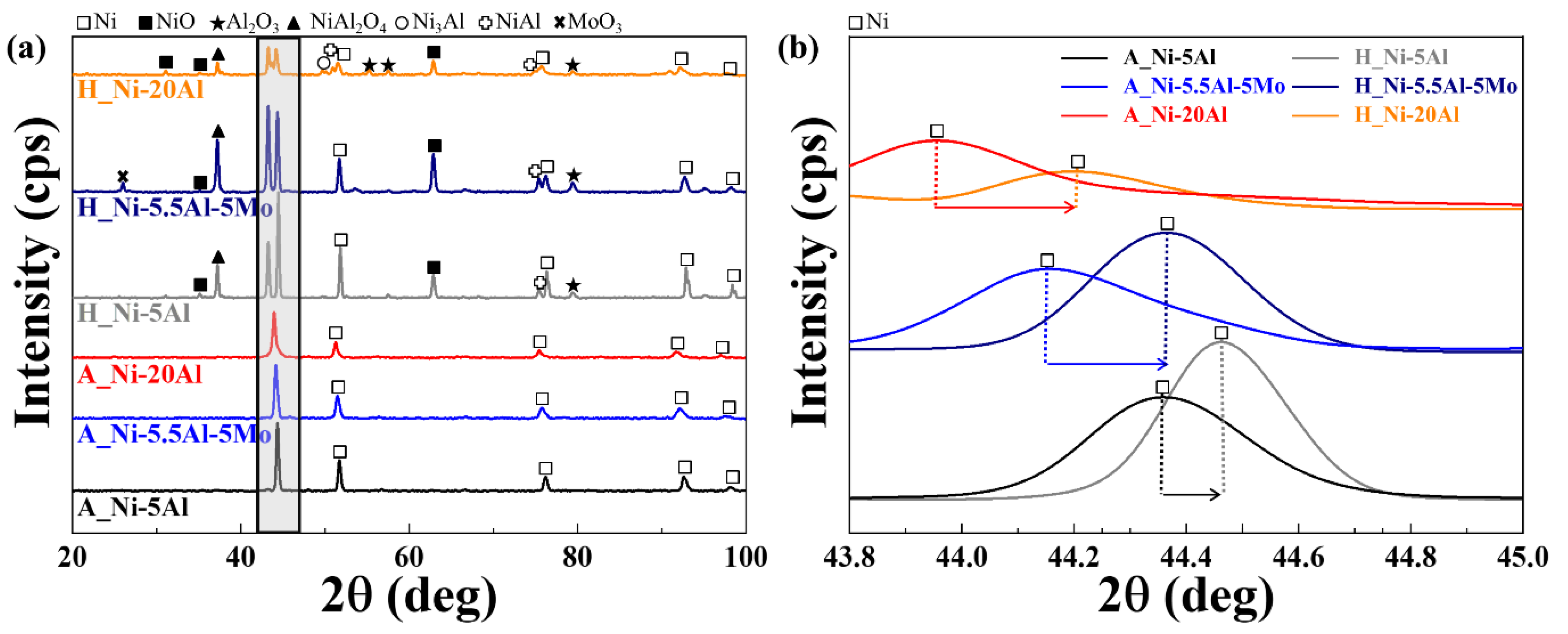
3.1. Characterizations of the as-Sprayed Coating Layers and after the High-Temperature Heat Exposure

The microstructures of the cross-sections of the as-sprayed and heat-exposed coating layers at 1050 °C are shown in Figure 1, which were obtained in the secondary electron (SE) beam mode. All the coating layers exhibited a lamellar structure parallel to the substrate, containing oxides, porosity, and splats. This is a typical microstructure of arc-sprayed coatings, where coating particles are not fully melted, or melted but react with oxygen in the atmosphere during the re-solidification process, leading to the formation of oxide and unmelted particles mixed with lamellae [27]. In each image, the black region represents the porosity that arises between the splats, where they are not fully melted, while the gray region is composed of unmelted particles, Ni-Al intermetallic phases, and Ni-Mo intermetallic phases, if present. The white region represents the oxides, which were identified from the EDS results shown in Table 2. Ni3Al and NiAl intermetallic phases were found in the Ni-5Al and Ni-20Al coatings, whereas only Ni3Al and NiAl intermetallic phases were formed in the Ni-5.5Al-5Mo coatings, where Mo dissolved in the Ni lattice to form a face-centered cubic solid solution without forming Ni-Mo intermetallic phases. In the case of Ni-20Al, delamination occurred between the coating layer and the substrate due to the difference in their coefficients of thermal expansion after high-temperature exposure. Aluminum diffused along the boundary after high-temperature exposure, extending the oxide region between the splats and causing aluminum depletion from the splats [33]. The weak adhesion strength and insufficient metal bonding between the splats not only reduce the mechanical properties of the coating but also provide accessible paths for oxygen diffusion, promoting internal oxidation of the coating at high temperatures.
Table 3 shows the area fraction of porosity, cracks, and intermetallic phases in each coating layer obtained using the ImageJ software. As the aluminum content increases, the area fraction of the oxide and porosity increases. Aluminum oxidizes rapidly when the coating material is deposited on the substrate, leading to a higher area fraction of oxides in Ni-20Al. The area fraction of the intermetallic phases, NiAl, and Ni3Al increases with the aluminum content, as aluminum has a strong tendency to dissolve into nickel and form intermetallic compounds [9]. Moreover, Ni-Al intermetallic compounds thermodynamically affect the bond strength between the coating layer and the substrate. The formation of Ni-Al intermetallic compounds depends on the reaction temperature, and the heat generated during the reaction provides the heat necessary for the metal bond between the coating and the substrate [27]. When exposed to high temperatures, all the coating layers tend to reach equilibrium by consuming more NiAl, resulting in an increase in the area fraction of NiAl. The diffusion coefficient of Al in NiAl is relatively high compared to Ni, and thus Ni-Al intermetallic compounds mainly consist of NiAl during high-temperature oxidation.
Figure 2 shows the X-ray diffraction values of the as-sprayed and heat-exposed Ni-5Al, Ni-20Al, and Ni-5.5Al-5Mo coating layers. In Figure 2a, which shows the detected XRD peaks of the as-sprayed coating layer, Ni (ICSD 00-004-0850) was detected, and in Figure 2b, which magnifies the gray shaded area on the graph, shows that as the Al content increased, the diffraction peaks of Ni became broader and shifted to lower Bragg angles. This is because, according to the Bragg lattice equation, as the angle decreases, the interplanar spacing increases due to the expansion of the FCC lattice structure [9,27]. This is caused by the different atomic radii of Ni, which acts as a solvent with an atomic radius of 1.24 Å, and Al and Mo, which act as solutes with atomic radii of 1.43 Å and 1.39 Å, respectively. In contrast, after heat exposure, the lattice constant decreased and the FCC structure contracted, showing a higher Bragg angle than the as-sprayed ones. Additionally, while only Ni peaks were detected in the as-sprayed coating layer, NiO, NiAl2O4, Mo oxide, Al2O3, and other compounds were detected in the heat-exposed layers.
Figure 3 shows the EBSD analysis of the particle size changes induced by the addition of Al and Mo. According to previous studies [27], Figure 3a A_Ni-5Al has a grain size of 4.41 μm, and Figure 3b A_Ni-5.5Al-5Mo and Figure 3c A_Ni-20Al have a particle size of 4.01 μm and 3.53 μm, respectively. The black areas in the images represent regions where measurement was impossible due to oxide formation. It can be observed that the grain size decreases as the amount of added elements increases, which is thought to be due to the difference in atomic radius between Al and Mo, which causes FCC expansion, leading to refinement of the particle size. Additionally, the as-sprayed coating layer was found to have a perpendicular structure in a lathed shape, with most particles surrounded by relatively smaller particles. After heat exposure at 1050 °C, the particle sizes of Ni-5Al, Ni-5.5Al-5Mo, and Ni-20Al increased to 7.27 μm, 5.50 μm, and 5.44 μm, respectively. The heat-exposed coating layers were uniformly rearranged via thermally active diffusion reconstruction, with the lath-shaped particles absorbing smaller grains in their surroundings to grow into uniformly shaped equiaxed grains.

3.2. Mechanical Properties of as-Sprayed and Heat-Exposed Ni-Al Coating Layers

Table 4 shows the comparison of coating layer matrix hardness. A_Ni-5Al exhibits a hardness value of 182.5 HV, while A_Ni-5.5Al-5Mo has a higher hardness value of 217.7 HV. The addition of elements in A_Ni-5.5Al-5Mo results in a 19.3% improvement in the mechanical properties compared to that of A_Ni-5Al. Furthermore, A_Ni-20Al demonstrates the highest hardness value of 404.5 HV, showing a remarkable 121.1% enhancement in mechanical properties compared to A_Ni-5Al. The increased mechanical properties are ascribed to the addition of elements, which leads to the formation of more oxides and intermetallic compounds, as well as to the reduction in grain size. After heat exposure, the coating layers have hardness values of 141.01 HV, experiencing a reduction of 22.7% compared to the as-sprayed state for A_Ni-5Al. A_Ni-5.5Al-5Mo exhibits a hardness value of 157.8 HV, showing a decrease of 27.5%. Additionally, A_Ni-20Al demonstrates a hardness value of 270.2 HV, experiencing the highest reduction of 33.2% compared to its as-sprayed state. The rapid decline in hardness values during high-temperature exposure is attributed to the occurrence of grain growth at elevated temperatures [34]. Although the mechanical properties of all three samples decrease sharply before and after heat exposure, heat-exposed Ni-20Al still has the best mechanical properties compared to the other two samples, despite a 33.2% decrease compared to the as-sprayed state.

3.3. Electrochemical Properties of Ni-Al Coatings before and after the High-Temperature Exposure in 3.5% NaCl Solution

3.3.1. Galvanic Corrosion Test

The potential difference between the anode and cathode metals within the electrolyte drives galvanic corrosion. When metals are in contact, their corrosion rates are influenced by their ionization tendencies. Noble metals act as cathodes, reducing corrosion rates, whereas active metals act as anodes, increasing corrosion rates [9]. Figure 4 shows the changes in galvanic potential and current measured in a 3.5 wt.% NaCl solution over 20 h to understand the galvanic behavior between the substrate and coating layer. A galvanic cell was formed due to the potential difference between the substrate and the Ni-Al coating layers, with the coating layer acting as the cathode and the substrate acting as the anode, leading to the corrosion of the substrate. In Figure 4a, the galvanic potential initially showed fluctuations for the first 200 min but then stabilized. However, A_Ni-5Al showed decreasing potential values over time and fluctuated continuously due to the ongoing corrosion of the substrate, which led to the formation of an oxide film on the substrate. The Ni-Al coating layers showed an increased current density over time due to the active oxidation reaction at the anodic substrate, which supplied electrons to the cathode coating layer. As for Ni-5Al, the continuous corrosion of the substrate led to the formation of an oxide film, which was removed by the cathodic coating layer, leading to fluctuating potential and current values.

3.3.2. Cyclic Potentiodynamic Polarization

To investigate the resistance to the pitting corrosion in the substrate and coating layer, the CPDP curves are presented in Figure 5. The electrochemical values obtained from the Tafel region are shown in Table 5. By observing the shape of the CPDP curves as shown, similar corrosion behaviors were confirmed for the as-sprayed and heat-exposed Ni-5Al, Ni-5.5Al-5Mo, and Ni-20Al. The coating layers of A_Ni-5Al, A_Ni-5.5Al-5Mo, H_Ni-5.5Al5Mo, and H_Ni-20Al have hysteresis loops. The size of the hysteresis loop is determined by the difference between the forward and reverse current densities, and it shows a decreased loop size with increasing Al content in Figure 5b,c, indicating that the restoration of damaged coating layers is difficult [35]. For the substrate Figure 5a, A_Ni-20Al in Figure 5b, and H_Ni-5Al and H_Ni-5.5Al-5Mo in Figure 5c and Table 5, the reverse potential (Erep) for the transition from the anode to the cathode is more negative than the forward potential (Ecorr), meaning that the corroded area acts as a cathode and continues to corrode. This indicates that the pit continuously grows along with its formation. For A_Ni-5.5Al-5Mo in Figure 5b and H_Ni-20Al in Figure 5c, the reverse potential for the transition from the anode to the cathode is more noble than the forward potential, indicating the resistance of the passive film in the coating layer. Thus, it implies that Erep, which is higher than Ecorr, exhibits higher resistance to localized corrosion in the as-sprayed Ni-5Al and Ni-5.5Al-5Mo [36,37]. Similarly, the corrosion current density also decreases with decreasing Al content, which follows a trend similar to that of the curves. This can be attributed to relatively lower porosity, oxide formation, and intermetallic compound formation compared to those of Ni-20Al. Ni-20Al exhibits a significantly higher current density due to the occurrence of localized corrosion caused by the high impurity content preferentially dissolved in the matrix. The A_Ni-5.5Al-5Mo coating layer has a property that interferes with the ion absorption of Mo, resulting in a stable passivation film [21,25], and the H_Ni-20Al coating layer delays general corrosion due to the formation of an oxide film on the surface after exposure to high temperatures. Furthermore, even after high-temperature exposure, the relatively noble Erep in Ni-20Al compared to Ecorr and lower current density than other coating layers demonstrate better corrosion resistance than the as-sprayed coating layer, which is attributed to the oxide layer formed on the surface resulting from the phase transformation of intermetallic compounds [14,36,37].

3.3.3. Electrochemical Impedance Spectroscopy

EIS tests before and after high-temperature exposure can be used to assess corrosion resistance with the addition of Al and Mo [38]. Figure 6 shows the diagrams of (a) and (b) Nyquist plots and (c) and (d) Bode plots for the as-sprayed and heat-exposed Ni-5Al, Ni-20Al, and Ni-5.5Al-5Mo. The diameter of the capacitance loop in the Nyquist plot is closely related to the charge transfer and represents higher charge transfer values and better corrosion resistance of the coating as the diameter increases [39,40].
As shown in Figure 6a,b, impedance can generally be characterized by a large semicircular capacitive loop. In addition, the charge transfer resistance of the passivation film means that the lower the capacitance impedance radius, the lower the resistance capacitance for charge transfer, and the higher the phase angle, the better the capacitance of the material and the higher the stability of the film. Therefore, the corrosion resistance of the as-sprayed Ni-5Al and heat-exposed Ni-20Al is the best. In other words, the corrosion resistance decreases in the order of Ni-5Al, Ni5.5Al-5Mo, and Ni-20Al in the as-sprayed coating, and in the opposite order, Ni-20Al improves the stability of the passive film at high temperatures. Furthermore, in the Nyquist plot of Figure 6b, two capacitance loops were observed for Ni-20Al and Ni-5.5Al-5Mo. This phenomenon is due to the deposition of a stable oxide film caused by the phase transition of intermetallic compounds on the coating surface. Additionally, Bode plots for Figure 6c,d show that the as-sprayed Ni-5Al, Ni-5.5Al-5Mo, and Ni-20Al exhibit high impedance values and maximum phase values in the low-frequency range, whereas the heat-exposed Ni-20Al, Ni-5.5Al-5Mo, and Ni-5Al exhibit high impedance values in the opposite order. Therefore, the passive films of Ni-5Al and Ni-20Al are the most stable in both the as-sprayed and heat-exposed states, as they have the highest phase and impedance values. EIS plots based on the Randles circuit model were used in Figure 6e,f to explain the impedance spectra results of the coating materials, which are shown in Table 6. While Ni-5Al exhibits the same circuit regardless of high-temperature exposure, H_Ni-5.5Al-5Mo and H_Ni-20Al show changes in the circuit due to improved corrosion resistance from the oxide film after the high-temperature heat exposure.
In the equivalent circuit, Rs represents the resistance index for the ion movement during pit formation and corrosion, which is the electrolyte resistance. R1 represents the electrical resistance value of the coating surface. Additionally, R2 represents the resistance index for the electrochemical reaction at the interface between the oxide film and the coating layer, indicating greater resistance to ion diffusion and electrochemical reactions [39]. CPE1 is a constant phase element that represents the dielectric characteristics of the surface coating, and CPE2 is a constant phase element that corresponds to the dielectric characteristics of the oxide film. The CPE value represents the impedance resistance by deviation from the ideal capacitive behavior and decreasing the uniformity of the coating surface or oxide film. The CPE value can be calculated from the EIS spectrum at a low frequency of approximately 0.01–1 Hz using Equation (1) [40,41].
Z C P E = ( Q j w α ) 1
The EIS parameter values, such as Q, j, w, and α, were calculated using the Gamry software. Q is the constant of CPE (Ω−1 ·sn cm2). j represents the current, ω represents the angular frequency (rad/s), and α is a dimensionless exponent (α = 0 for resistive CPE and α = 1 for ideal capacitive behavior of CPE) where n is a value between 0 and 1 in the actual electrolyte. According to the results, the as-sprayed coatings showed higher corrosion resistance in the order of Ni-5Al, Ni-5.5Al-5Mo, and Ni-20Al. However, in the heat-exposed coatings, the order was reversed, with Ni-20Al showing the highest resistance. This was attributed to the difference in the diffusion coefficients of Ni and Al in Ni3Al and NiAl during the phase transformation process of Ni3Al at high temperatures, resulting in the formation of an oxide film on the surface. According to Lee’s research [42], during the formation process of the oxide film, the formation processes of Al2O3, NiAl2O4, and NiO compete with each other, and reactions occur. The activity of NiO is higher than that of Al2O3, so Ni moves more rapidly toward the surface, creating nuclei of NiO, but the protective ability of NiO is lower than that of Al2O3, so Al2O3 is formed beneath the NiO layer as oxygen diffuses [42,43]. The increase in elemental composition provides a driving force for the phase transformation activity of the intermetallic compound to form a thicker oxide film [14,42,43].

3.3.4. Immersion Test

Table 7 shows the corrosion rates of Ni-Al and Ni-Al-Mo coating layers in 3.5% NaCl solution at 298 K for 360 h, calculated using Equation (2), where W (mg) is the weight loss, A (cm2) is the exposed area, T (h) is the immersion time, and D (g/cm3) is the density.
C o r r o s i o n   r a t e m p y = K × W A × T × D
The corrosion rate showed a decreasing trend as the Al content increased. In the as-sprayed state, Ni-5Al exhibited a corrosion rate of 13.23 mm/y, whereas Ni-5.5Al-5Mo showed a slightly improved corrosion resistance with a corrosion rate of 12.72 mm/y, representing a 3.98% enhancement compared to Ni-5Al. However, Ni-20Al demonstrated a decrease in corrosion resistance, with a corrosion rate of 14.52 mm/y, representing an 8.94% reduction compared to Ni-5Al.
Interestingly, after high-temperature exposure, the corrosion rates of the coatings exhibited different behaviors compared to the immersion test in the as-sprayed state. Ni-5Al displayed a corrosion rate of 12.64 mm/y, indicating a 4.47% decrease compared to the as-sprayed state. On the other hand, Ni-5.5Al-5Mo exhibited a slightly decreased corrosion rate of 12.54 mm/y, representing a 1.41% increase. Notably, Ni-20Al showed a significant decrease in corrosion rate after heat exposure, with a corrosion rate of 11.48 mm/y, representing a substantial 20.93% increase compared to its as-sprayed state.
Furthermore, when considering the cross-sectional corrosion rates, Ni-5Al exhibited a corrosion rate of 14.76 mm/y, Ni-5.5Al-5Mo showed a lower rate of 10.89 mm/y, and Ni-20Al demonstrated the lowest rate of 8.77 mm/y. These results highlight the decreased corrosion rates as the Al content increased. Additionally, Ni-5.5Al-5Mo and Ni-20Al exhibited a more rapid increase in the corrosion rate on the surface rather than on the cross-section. Conversely, Ni-5Al showed a faster cross-sectional corrosion rate, indicating severe damage caused by galvanic corrosion in the substrate.
Figure 7 and Table 8 show the corrosion morphology and EDS analysis results of the coatings immersed in a 3.5% NaCl solution for 360 h at 298 K. The A_Ni-5Al, A_Ni-5.5Al-5Mo, and A_Ni-20Al coatings deposited via twin wire arc spraying consist of an inhomogeneous matrix that includes pores, oxides, and unmelted particles. Oxides have a higher solubility in electrolytes and are deeply related to the corrosion resistance of the coatings. The porosity provides a pathway for chloride ions to penetrate rapidly into the electrolyte and creates a route for localized corrosion, where oxygen diffuses slowly into the pores, leading to the formation of a galvanic cell that acts as an initiation point for pitting corrosion when the coating is only exposed to the corrosion atmosphere [9,17]. The surface morphologies of Figure 7a A_Ni-5Al and Figure 7c A_Ni-20Al coating layers shown in Figure 7 exhibit pitting corrosion with numerous pits marked with yellow circle and a large oxide film that protects the coating surface. In Figure 7a, the protective film identified by EDS analysis is shown in Table 8. A_Ni-5Al remains relatively coherent and is not dissolved in the solution compared to the films of A_Ni-5.5Al-5Mo and A_Ni-20Al. In the case of Figure 7b, no large oxide film is observed, but uniform corrosion occurs with the detection of the corrosion products. This is due to the formation of a Mo oxide film during exposure to chloride ions, and the Mo corrosion product formed in the pits inhibits pit growth, demonstrating the best corrosion resistance. In Figure 7d–f, galvanic corrosion occurs between the coating layer and substrate due to the potential difference, exhibiting substrate corrosion. The extent of damage varies according to the galvanic potential difference. In the case of Ni-5Al, the interface is severely damaged when the substrate is dissolved, whereas Figure 7b shows a relatively better condition compared to Figure 7a. In Figure 7c Ni-20Al, the detection of metal components in the oxide film observed at the interface indicates that the oxide film formed during the corrosion process acts as a protective layer, blocking the metal surface from chloride ions. After exposure to high temperature, the coated surface morphologies of Figure 7d–f in the immersed state show a similar pattern to that of the as-sprayed samples, with Figure 7f exhibiting the most preserved coating layer, due to the formation of NiO and Al2O3. The abundant intermetallic compounds present in each coating layer protect the coating surface from the NaCl solution via the formation of a Ni oxide film and Al2O3 during exposure to high temperature.

4. Conclusions

In this study, the microstructure, mechanical properties, and corrosion characteristics of twin-wire-arc-sprayed Ni-Al coatings (Ni-5Al, Ni-5.5Al-5Mo) were analyzed with respect to the addition of Al and Mo. These properties were compared after exposure to high temperatures. The summarized results of each experiment are as follows:
  • The Ni-Al and Ni-Al-Mo coating layers exhibited typical lamellar microstructures resulting from the twin wire arc spray, with increasing porosity and oxide content as the Al content increased. Delamination was observed in the Ni-20Al coating layer after thermal exposure. The addition of Al elements resulted in the miniaturization of the grain size and various oxides after high-temperature exposure. Ni-20Al exhibited the excellent mechanical properties among the coatings, under both as-sprayed and high-temperature heat exposure.
  • Following the corrosion tests, the galvanic corrosion potential difference between the substrate and the coating layers decreased with increasing Al content. Ni-5Al and Ni-20Al exhibited localized galvanic corrosion around the intermetallic compounds and oxides, whereas Ni-5.5Al-5Mo showed uniform corrosion. However, the formation of an oxide layer resulting from the phase transformation of intermetallic compounds after exposure to high temperatures improved the corrosion resistance, demonstrating the superior corrosion properties of Ni-20Al. These results emphasize the correlation between the corrosion behavior and the composition of the passivation film and support the potential application of the Ni-5.5Al-5Mo coating as a protective layer against the pitting corrosion of the substrate.

Author Contributions

Conceptualization, J.B. and E.L.; methodology, J.B.; software, J.B.; validation, J.B. and E.L.; formal analysis, J.B.; investigation, J.B.; resources, J.B. and E.L.; data curation, J.B.; writing—original draft preparation, J.B.; writing—review and editing, J.B. and E.L.; visualization, J.B.; supervision, E.L.; project administration, E.L.; funding acquisition, E.L. All authors have read and agreed to the published version of the manuscript.

Funding

This work was supported by the National Research Foundation of Korea (NRF) grant funded by the Korean government (NRF-2019R1I1A3A01062863) and was conducted with the support of the Korea Basic Science Institute (National Research Facilities and Equipment Center) grant funded by the Ministry of Education (grant No. 2022R1A6C101B738).

Institutional Review Board Statement

Not applicable.

Informed Consent Statement

Not applicable.

Data Availability Statement

The data presented in this study are available upon request from the corresponding authors.

Conflicts of Interest

The authors declare no conflict of interest.

References

  1. Bandgar, S.; Gupta, C.; Rao, G.; Malik, P.; Singh, R.N.; Sridhar, K. Fatigue Crack Growth Rate Behaviour of HSLA Steel at Varying Load Amplitudes. Procedia Struct. Integr. 2019, 14, 330–336. [Google Scholar] [CrossRef]
  2. Wu, W.; Wang, Q.; Yang, L.; Liu, Z.; Li, X.; Li, Y. Corrosion and SCC initiation behavior of low-alloy high-strength steels microalloyed with Nb and Sb in a simulated polluted marine atmosphere. J. Mater. Res. Technol. 2020, 9, 12976–12995. [Google Scholar] [CrossRef]
  3. Chen, X.; Yuming, H.; Yucheng, L. Microstructure and properties of 700 MPa grade HSLA steel during high temperature deformation. J. Alloy. Compd. 2015, 631, 225–231. [Google Scholar] [CrossRef]
  4. Lee, J.; Jeong, Y.; Shim, D.; Lee, E. Microstructural evolution and martensitic transformation in FeCrV alloy fabricated via additive manufacturing. Mater. Sci. Eng. A 2021, 809, 140943. [Google Scholar] [CrossRef]
  5. Jeong, Y.; Lee, J.; Lee, E.; Shim, D. Microstructures and Mechanical Properties of Deposited Fe-8Cr-3V-2Mo-2W on SCM420 Substrate Using Directed Energy Deposition and Effect of Post-Heat Treatment. Materials 2021, 14, 1231. [Google Scholar] [CrossRef]
  6. Amin, S.; Panchal, H. A review on thermal spray coating processes. Transfer 2016, 2, 556–563. [Google Scholar]
  7. Yang, G.; Du, Y.; Chen, S.; Ren, Y.; Ma, Y. Effect of secondary passivation on corrosion behavior and semiconducting properties of passive film of 2205 duplex stainless steel. J. Mater. Res. Technol. 2021, 15, 6828–6840. [Google Scholar] [CrossRef]
  8. Wang, J.; Wang, G.; Liu, J.; Zhang, L.; Wang, W.; Li, Z.; Wang, Q.; Sun, J. Microstructure of Ni-Al powder and Ni-Al composite coatings prepared by twin-wire arc spraying. Int. J. Miner. Metall. Mater. 2016, 23, 810–818. [Google Scholar] [CrossRef]
  9. Xu, C.; Du, L.; Yang, B.; Zhang, W. The effect of Al content on the galvanic corrosion behaviour of coupled Ni/graphite and Ni–Al coatings. Corros. Sci. 2011, 53, 2066–2074. [Google Scholar] [CrossRef]
  10. Abuwarda, N.; Lopez, A.J.; Lopez, M.D.; Utrilla, M.V. High temperature corrosion and wear behavior of HVOF-sprayed coating of Al2O3-NiAl on AISI 304 stainless steel. Surf. Coat. Technol. 2019, 359, 35–46. [Google Scholar] [CrossRef]
  11. Saladi, S.; Menghani, J.; Prakash, S. A study on the cyclic oxidation behavior of detonation-gun-sprayed Ni-5Al coatings on Inconel-718 at 900 °C. J. Mater. Eng. Perform. 2014, 23, 4394–4403. [Google Scholar] [CrossRef]
  12. Morgiel, J.; Poliarus, O.; Pomorska, M.; Maj, L.; Szlezynger, M. Thermal stability of plasma-sprayed NiAl/CrB2 composite coatings investigated through in-situ TEM heating experiment. Mater. Charact. 2020, 159, 110068. [Google Scholar] [CrossRef]
  13. Moon, G.; Lee, E. Combined effects of optimized heat treatment and nickel coating for the improvement of interfacial bonding in aluminum–iron alloys hybrid structures. Appl. Sci. 2021, 11, 1501. [Google Scholar] [CrossRef]
  14. Shabani, A.; Nahvi, S.M.; Raeissi, K. Effect of heat treatment on structure and oxidation resistance of flame-sprayed Ni-20 wt.% Al on carbon steel. J. Therm. Spray Technol. 2021, 30, 739–753. [Google Scholar] [CrossRef]
  15. Bang, J.; Byon, E.; Lee, E. Effects of Na2B4O7·10H2O on microstructure and mechanical properties of AlSi7Mg0.3 and AlSi10MnMgAlSi10MnMg alloys. J. Adv. Mar. Eng. Technol. 2021, 45, 363–370. [Google Scholar] [CrossRef]
  16. Xanthopoulou, G.; Marinou, A.; Vekinis, G.; Lekatou, A.; Vardavoulias, M. Ni-Al and NiO-Al composite coatings by combustion-assisted flame spraying. Coatings 2014, 4, 231–252. [Google Scholar] [CrossRef] [Green Version]
  17. Jafari, R.; Sadeghi, E. High-temperature corrosion performance of HVAF-sprayed NiCr, NiAl, and NiCrAlY coatings with alkali sulfate/chloride exposed to ambient air. Corros. Sci. 2019, 160, 108066. [Google Scholar] [CrossRef]
  18. Mahesh, R.A.; Jayaganthan, R.; Prakash, S. Microstructure characterization and hardness evaluation of HOVF sprayed Ni–5Al coatings on Ni- and Fe-based superalloys. J. Mater. Process. Tech. 2009, 209, 3501–3510. [Google Scholar] [CrossRef]
  19. Chen, H.C.; Pfender, E. Microstructure of plasma-sprayed Ni–Al alloy coating on mild steel. Thin Solid Films. 1996, 280, 188–198. [Google Scholar] [CrossRef]
  20. Sugimoto, K.; Sawada, Y. The role of molybdenum additions to austenitic stainless steels in the inhibition of pitting in acid chloride solutions. Corros. Sci. 1977, 17, 425–445. [Google Scholar] [CrossRef]
  21. Clayton, C.R.; Lu, Y.C. A Bipolar Model of the Passivity of Stainless Steel: The Role of Mo Addition. J. Electrochem. Soc. 1986, 133, 2465–2473. [Google Scholar] [CrossRef]
  22. Landolt, D.; Mischler, S.; Vogel, A.; Mathieu, H.J. Chloride Ion Effects on Passive Films on FeCr and FeCrMo Studied by AES, XPS and SIMS. Corros. Sci. 1990, 31, 431–440. [Google Scholar] [CrossRef]
  23. Kannur, K.H.; Yaqub, T.B.; Huminiuc, T.; Polcar, T.; Pupier, C.; Héau, C.; Cavaleiro, A. Synthesis and structural properties of Mo-SN sputtered coatings. Appl. Sci. 2020, 527, 146790. [Google Scholar]
  24. Tian, J.J.; Yao, S.W.; Luo, X.T.; Li, C.X.; Li, C.J. An effective approach for creating metallurgical self-bonding in plasma-spraying of NiCr-Mo coating by designing shell-core-structured powders. Acta Mater. 2016, 110, 19–30. [Google Scholar] [CrossRef]
  25. Ha, H.Y.; Lee, T.H.; Bae, J.H.; Chun, D.W. Molybdenum effects on pitting corrosion resistance of FeCrMnMoNC austenitic stainless steels. Metals 2018, 8, 653. [Google Scholar] [CrossRef] [Green Version]
  26. Hashimoto, K.; Asami, K.; Teramoto, K. An X-ray photo-electron spectroscopic study on the role of molybdenum in increasing the corrosion resistance of ferritic stainless steels in HCl. Corros. Sci. 1979, 19, 3–14. [Google Scholar] [CrossRef]
  27. Bang, J.; Kwon, H.; Byon, E.; Lee, E. Understanding of microstructures and mechanical properties of thermal sprayed Ni-based coatings with Al and Mo addition. J. Adv. Mar. Eng. Technol. 2022, 46, 342–347. [Google Scholar] [CrossRef]
  28. Hamed, K.N.; El-Mahallawy, N.; Mokhtar, M.O.A. An investigation of plasma sprayed nickel-based and pure aluminum coatings on austenitic stainless steel AISI 304. IOP Conf. Ser. Mater. Sci. Eng. 2021, 1172, 012025. [Google Scholar] [CrossRef]
  29. Wang, J.X.; Sun, J.F.; Wang, Z.P. Effect of Heat Treatment to Ni-20 wt.% Al Coating Diffusion. Adv. Mater. Res. 2013, 621, 75–78. [Google Scholar] [CrossRef]
  30. Kornienko, E.; Gulyaev, I.; Smirnov, A.; Nikulina, A.; Ruktuev, A.; Kuzmin, V.; Tuezov, A. Microstructure and properties of Ni-Al coatings obtained by conventional and high-velocity atmospheric plasma spraying. Results Surf. Interfaces 2022, 6, 100038. [Google Scholar] [CrossRef]
  31. Mrdak, M.R. Mechanical properties and metallographic analysis of plasma spray APS-Ni5. 5 wt.% Al5 wt.% Mo coatings. Vojnoteh. Glas. 2019, 67, 573–587. [Google Scholar] [CrossRef]
  32. Kumar, S.; Kumar, M.; Handa, A. Comparative study of high temperature oxidation behavior and mechanical properties of wire arc sprayed NiCr and NiAl coatings. Eng. Fail. Anal. 2019, 106, 104173. [Google Scholar] [CrossRef]
  33. Wang, Y.; Yang, Y.; Yan, M.F. Microstructures, hardness and erosion behavior of thermal sprayed and heat treated NiAl coatings with different ceria. Wear 2007, 263, 371–378. [Google Scholar] [CrossRef]
  34. Man, T.; Hu, C.; Lu, H.; Chen, Y.; Lin, Y.; Dong, H. Effect of annealing temperature on microstructure and hardness of Ni-Co alloy coating. Mater. Today Commun. 2022, 31, 103244. [Google Scholar] [CrossRef]
  35. Esmailzadeh, S.; Aliofkhazraei, M.; Sarlak, H. Interpretation of cyclic potentiodynamic polarization test results for study of corrosion behavior of metals: A review. Phys. Chem. Surf. 2018, 54, 976–989. [Google Scholar] [CrossRef]
  36. Lekatou, A.G.; Sfikas, A.K.; Karantzalis, A.E. The influence of the fabrication route on the microstructure and surface degradation properties of Al reinforced by Al9Co2. Materials Chem. Phys. 2017, 200, 33–49. [Google Scholar] [CrossRef]
  37. Lekatou, A.; Sfikas, A.K.; Petsa, C.; Karantzalis, A.E. Al-Co alloys prepared by vacuum arc melting: Correlating microstructure evolution and aqueous corrosion behavior with Co content. Metals 2016, 6, 46. [Google Scholar] [CrossRef] [Green Version]
  38. Zhou, Z.; Min, X.; Wan, S.; Liu, J.; Liao, B.; Guo, X. A novel green corrosion inhibitor extracted from waste feverfew root for carbon steel in H2SO4 solution. Results Eng. 2023, 17, 100971. [Google Scholar] [CrossRef]
  39. Liao, B.; Ma, S.; Zhang, S.; Li, X.; Quan, R.; Wan, S.; Guo, X. Fructus cannabis protein extract powder as a green and high effective corrosion inhibitor for Q235 carbon steel in 1 M HCl solution. Int. J. Biol. Macromol. 2023, 239, 124358. [Google Scholar] [CrossRef] [PubMed]
  40. Hajideh, M.R.; Farahani, M.; Pakravan, M.; Shahmirzalo, A. Corrosion resistance and hydrophilic properties of plasma sprayed Ni + 5% Al coatings. Heliyon 2019, 5, e01920. [Google Scholar] [CrossRef] [PubMed] [Green Version]
  41. Popczyk, M.; Kubisztal, J.; Swinarew, A.S.; Waśkiewicz, Z.; Stanula, A.; Knechtle, B. Corrosion resistance of heat-treated Ni-W alloy coatings. Materials 2020, 13, 1172. [Google Scholar] [CrossRef] [PubMed] [Green Version]
  42. Lee, W.H. Oxidation and sulfidation of Ni3Al. Mater. Chem. Phys. 2002, 76, 26–37. [Google Scholar] [CrossRef]
  43. Pettit, F.; Randkle, E.; Felten, E. Formation of NiAl2O4 by solid state reaction. J. Am. Ceram. Soc. 1966, 49, 199–203. [Google Scholar] [CrossRef]
Figure 1. Cross-sectional SEM microstructure images of (ac) as-sprayed and (df) heat-exposed coating layers in SE modes; (a) A_Ni-5Al, (b) A-Ni-5.5Al-5Mo, (c) A_Ni-20Al, (d) H_Ni-5Al, (e) H_Ni-5.5Al-5Mo, and (f) H_Ni-20Al.
Coatings 13 01069 g001
Figure 2. X-ray diffraction peaks of (a) as-sprayed and heat-exposed Ni-5Al, Ni-5.5Al-5Mo, and Ni-20Al coating layers, and (b) enlarged graph of the gray box of (a).
Coatings 13 01069 g002
Figure 3. EBSD maps and grain size (GS) of (ac) as-sprayed and (df) heat-exposed coating layers; (a) A_Ni-5Al (GS: 4.41 μm), (b) A-Ni-5.5Al-5Mo (GS: 4.01 μm), and (c) A_Ni-20Al (GS: 3.53 μm), (d) H_Ni-5Al (GS: 7.27 μm), (e) H_Ni-5.5Al-5Mo (GS: 5.50 μm), and (f) H_Ni-20Al (GS: 5.44 μm).
Coatings 13 01069 g003
Figure 4. Evolution of (a) galvanic potential and (b) current density of coating layers depending on time.
Coatings 13 01069 g004
Figure 5. Cyclic potentiodynamic polarization curves of (a) substrate, (b) as-sprayed, and (c) heat-exposed of Ni−5Al, Ni−5.5Al-5Mo, and Ni−20Al coating layers.
Coatings 13 01069 g005
Figure 6. Nyquist plot diagrams of (a) as-sprayed and (b) heat-exposed coating layers, and Bode plot diagrams of (c) as-sprayed and (d) heat-exposed coating layers; (e,f) are equivalent circuit diagrams used for the analysis of impedance spectra for coating layers; (a,c) A_Ni-5Al, A-Ni-5.5Al-5Mo, and A_Ni-20Al, (b,d) H_Ni-5Al, H_Ni-5.5Al-5Mo, and H_Ni-20Al, (e) A_Ni-5Al, A_Ni-5.5Al-5Mo, A_Ni-20Al, and H_Ni-5Al, and (f) H_Ni-5Al, H_Ni-5.5Al-5Mo, and H_Ni-20Al, respectively. Rs: diffusion resistance of the electrolyte, R2: oxide film resistance, R1: charge transfer resistance of the coating surface, CPE1: constant phase element of the coating layer, CPE2: CPE of the oxide film.
Coatings 13 01069 g006
Figure 7. Microstructure of the surface of (ac) as-sprayed and (gi) heat-exposed coating layers and the cross-section of (df) as-sprayed coating layers after 15 days of immersion test; (a,d) A_Ni-5Al, (b,e) A-Ni-5.5Al-5Mo, (c,f) A_Ni-20Al, (d) H_Ni-5Al, (e) H_Ni-5.5Al-5Mo, and (i) H_Ni-20Al.
Coatings 13 01069 g007
Table 1. Process parameters of twin wire arc spray coating.
Spray Parameters (Units)Settings
Coating materialsNi-5AlNi-5.5Al-5MoNi-20Al
Wire diameter (mm)1.61.61.6
Voltage (V)363636
Current (A)250250200
Air pressure (psi)707070
Spray Distance (mm)200200200
Gun spraying angle (°)909090
Table 2. EDS qualitative analysis of the points in Figure 1.
Number Chemical Compositions (at. %)
NiAlO
No. 130.3369.67-
No. 272.6127.39-
No. 3-43.5656.44
No. 428.7871.22-
Table 3. Area fraction of porosity, oxides, and intermetallic phases of the cross-sectional microstructure of the as-sprayed and heat-exposed coating layers using ImageJ software.
Coating MaterialsNi-5AlNi-5.5Al-5MoNi-20Al
Area Fraction (%)As SprayedHeat ExposedAs SprayedHeat ExposedAs SprayedHeat Exposed
Porosity1.481.141.511.151.971.17
(±0.14)(±0.17)(±0.15)(±0.11)(±0.11)(±0.16)
Oxide1.921.421.911.572.252.01
(±0.16)(±0.12)(±0.18)(±0.23)(±0.16)(±0.21)
Intermetallic phase0.620.600.630.610.680.64
(±0.15)(±0.10)(±0.14)(±0.12)(±0.12)(±0.11)
Table 4. Microhardness values of as-sprayed and heat-exposed coating layers.
Mechanical PropertiesHardness (HV)
Measurement LocationAs SprayedHeat Exposed
Matrix of coating layerNi-5Al182.5 (±11.8)141 (±15.1)
Ni-5.5Al-5Mo217.7 (±7.8)157.8 (±18.8)
Ni-20Al404.5 (±15)270.2 (±22.2)
Table 5. Electrochemical values of CPDP tests of the substrate, as-sprayed and heat-exposed coating layers.
MaterialsAs SprayedHeat Exposed
Ecorr
(mVSCE)
Icorr
(mA/m2)
Erep
(mVSCE)
Ecorr
(mVSCE)
Icorr
(mA/m2)
Erep
(mVSCE)
Substrate−620118−806---
Ni-5Al−467177−482−445550−465
Ni-5.5Al-5Mo−502113−390−448483−426
Ni-20Al−384199−439−531108−436
Table 6. Fitting parameters for the EIS results of the as-sprayed and heat-exposed coating layers.
ConditionRs
(Ωcm2)
R1
(Ωcm2)
R2
(Ωcm2)
CPE1
−1sncm 2)
CPE2
−1sncm 2)
Samples
As sprayedNi-5Al20.764.23 × 104-1.28 × 10⁻⁴-
Ni-5.5Al-5Mo19.813.78 × 104-1.42 × 10⁻⁴-
Ni-20Al16.843.07 × 104-1.06 × 10⁻⁴-
Heat exposedNi-5Al17.553.77 × 1043.17 × 1031.86 × 10−41.21 × 10⁻⁴
Ni-5.5Al-5Mo18.384.10 × 1045.47× 1031.23 × 10−41.37 × 10⁻⁴
Ni-20Al22.285.18 × 1047.05 × 1032.09 × 10−42.36 × 10⁻⁴
Table 7. Corrosion rate of the as-sprayed and heat-exposed coating layers after 15 days of immersion tests.
Coating LayersAs Sprayed (mm/y)Heat Exposed (mm/y)
SurfaceCross SectionSurface
Ni-5Al13.2314.7612.64
Ni-5.5Al-5Mo12.7210.8912.54
Ni-20Al14.528.7711.48
Table 8. EDS qualitative analysis of the marks in Figure 7.
NumberChemical Compositions (at.%)
AlMoO
No. 132.18-67.82
No. 2-64.6735.33
No. 340.02-59.98
No. 438.56-32.87
No. 535.78-64.22
No. 637.82-62.18
No. 729.77-70.23
Disclaimer/Publisher’s Note: The statements, opinions and data contained in all publications are solely those of the individual author(s) and contributor(s) and not of MDPI and/or the editor(s). MDPI and/or the editor(s) disclaim responsibility for any injury to people or property resulting from any ideas, methods, instructions or products referred to in the content.

