Article

Morphology and Composition of the Third Body on the Friction Surface of an Organic Composite Railway Brake Shoe

1
Metals and Chemistry Research Institute, China Academy of Railway Sciences Corporation Limited, Beijing 100081, China
2
Standards and Metrology Research Institute, China Academy of Railway Sciences Corporation Limited, Beijing 100081, China
*
Author to whom correspondence should be addressed.
Coatings 2023, 13(5), 952; https://doi.org/10.3390/coatings13050952
Submission received: 30 April 2023 / Revised: 14 May 2023 / Accepted: 17 May 2023 / Published: 19 May 2023
(This article belongs to the Special Issue Friction, Wear, Lubrication and Mechanics of Surfaces and Interfaces)

Abstract

:
Friction properties are significantly affected by third bodies (films formed on friction surfaces). However, the study of their composition and structure remains incomplete. For this reason, an organic composite railway brake shoe was tested at an initial braking speed of 125 km/h using a full-scale dynamometer. A third body with a thickness of ~120 μm was obtained, and its morphology and composition were analyzed using a multiple techniques. The results indicated that the third body had a layered structure. The upper surface was smoother than the lower surface. The carbon content on the upper surface decreased by 68.01%, and the iron content increased by 11.85 times in relation to that on the lower surface. Compared to the brake shoe, the iron content of the third body increased by 272.81%, and most of the iron was oxidized. Furthermore, the content of barium, calcium, and silicon decreased by more than 33%, and the crystalline structures of the inorganic filler materials, such as graphite and barium sulfate, were destroyed, with new crystalline structures appearing. Finally, the residual weight at 650 °C increased from 90.35% to 96.59%. This research could provide a reference for exploring the friction and wear mechanisms of organic composite railway brake shoes.

1. Introduction

The brake system is an important part of railway locomotives and vehicles, and organic composite railway brake shoes are the key components of the braking system. Under the conditions of high-speed and heavy-load braking, the surface of organic composite railway brake shoes produces wear debris, which forms a friction film, called the “third body”, under complex physical and chemical reactions [1].
When the friction properties of organic composite railway brake shoes were tested using a full-scale dynamometer, we found that the friction coefficient measured at the same initial braking speed was directly related to the previous initial braking speed. The morphology of the third body was different at different initial velocities. This indicated that different third bodies were formed at different initial braking speeds. It is very important to analyze the morphology and composition of the third body in order to explore the friction and wear mechanisms of organic composite railway brake shoes. For this reason, we carried out third body characterization and analysis.
The third body can significantly change the contact conditions of a sliding interface and directly decrease the friction coefficient. This phenomenon can be observed in many friction pairs, such as steel–steel [2,3], polymer–polymer [4], alloy–alloy [5,6], and carbon–carbon pairs [7]. Many scholars have studied the composition and morphology of third bodies. The composition of the third body mainly originates from the friction pair, but it can be significantly different from the friction pair, often containing oxides, as well as products of chemical reactions [8]. The morphology can be divided into two types: loose granular films [9] and dense sheet films [10,11]. In addition, some scholars have studied the influencing factors of third body composition, as well as the formation process and mechanism of movement. It was found that the composition of the third body is affected by the material characteristics of the friction pair and changes with the friction temperature [12], velocity [13], pressure [14], and other factors [15].
There are two problems in the study of third bodies. First, the braking speed and braking energy of the testing machine used in the present study were low, and there was a large gap between the results and actual train braking. Most of the research in the literature was carried out on pin-on-disc friction testing machines. The simulated temperature and speed of these machines are significantly lower than the actual values. However, when a train is braking, the speed and axle load are very high, and the local temperature can be as high as 500 °C [16]. Significant differences between different equipment have been reported, with full-scale equipment closer to actual equipment [8]. An organic composite railway brake shoe is a composite material made of a binder, filler, and fiber [17,18]. Compared to metal friction materials, the composition of organic composite railway brake shoes is more complex. The formation and composition of the third body of the synthetic brake shoe are more easily affected by the braking conditions, such as the initial braking speed, pressure, and temperature [19]. Second, compared with the third bodies of metal friction pairs, there are few reports on the third bodies of organic composite railway brake shoes, and they are not comprehensive. For example, although scholars such as Yin et al. [20,21] and Ghosh et al. [22] studied the morphology of third bodies, they did not study the composition. Monreal et al. [23] studied the morphology and elemental composition of third bodies using scanning electron microscopy and energy spectroscopy; however, the structural changes of inorganic fillers were not studied.
The common initial braking speeds of a full-scale dynamometer include 35, 55, 75, 95, 105, and 125 km/h. To study the morphology and composition of the third body of the organic composite railway brake shoe friction surface, an initial braking speed of 125 km/h was used. The third body of the friction surface was obtained, and the structure, morphology, and composition of the third body were systematically studied. The formation of the third body on the surface of the organic composite railway brake shoe was revealed.
The morphology and composition of a third body have not yet been studied with a full-scale dynamometer. When using a full-scale dynamometer, the test process is closer to the actual working conditions than when using a small machine, and the experimental results for the third body are closer to the real working conditions. In this work, a variety of methods were used to analyze the third body. The information obtained was more comprehensive. In particular, the morphology and composition of the cross section of the third body were first revealed. The changes in the crystal structure of the third body’s inorganic filler were also elucidated. Different methods of analysis provided different information. The results of different methods of analysis were used to verify each other, and these findings could be used for reference in composition research. The information on the morphology and structure of the third body obtained in this study may provide a reference for the study of friction and wear mechanisms.

2. Materials and Methods

2.1. Test Sample

Tests were conducted on an organic composite railway brake shoe (LH2) (Taiyuan Locomotive Vehicles Fittings Factory, Taiyuan, China) sample produced in September 2022. It was known to contain the following components: rubber, zinc oxide, stearic acid, sulfur, accelerant, graphite, barium sulfate, calcium carbonate, mineral fiber, feldspar, bauxite, and no asbestos. The wheel material was CL 60 steel.

2.2. Sample Preparation

A sample was collected from near the back of an organic composite railway brake shoe. It was marked as sample #1. A braking test was performed using a full-scale dynamometer (as shown in Figure 1) according to TB/T 3104.1-2020 at an initial braking speed of 125 km/h. The axle weight was 23,000 kg, and the pressing force was 20 kN. The temperatures of the laboratory, wheel, and brake shoe were all room temperature. When the wheel (840 mm diameter) reached a speed of 125 km/h, the motor was turned off and the wheel rotated by inertia only, before 20,000 N of force was applied to press the brake shoe against the wheel until the wheel stopped completely. The friction between the brake shoe and wheel caused the wheel to slow down and stop. The experiment was over when the wheel was stationary. The test process comprised dry braking. The surface of the organic composite railway brake shoe was scraped by a scalpel after braking to collect the third body, which was marked as sample #2. For more details on the procedures, refer to the standard GB/T 3104.1-2020. This standard can also be obtained by contacting the first author. Digital photos of the brake shoe and a schematic diagram of the locations of the samples are shown in Figure 2.

2.3. Test Rig and Measurements

2.3.1. Microscopy

The morphology of the third body was analyzed using optical microscopy (SX-5, Shanghai Optical Instrument No. 1 Factory, Shanghai, China) and scanning electron microscopy (SEM; QUANTA 400, FEI Company, Hillsboro, OR, USA). The highest voltage of the SEM was 20 kV.

2.3.2. X-Ray Photoelectron Spectroscopy (XPS)

The elements were analyzed by X-ray photoelectron spectroscopy (XPS, PHI-QUANTERA II, ULVAC-PHI, Inc, Kanagawa, Japan) using Al K-rays (hν = 1486.60 eV, full width at half maximum = 0.68 eV) with a scan area of 0.8 mm2, power of 250 W, and a vacuum of 1.60 × 10⁻⁶ Pa. The binding energies of the core electrons of the elements were calibrated with adventitious carbon at a binding energy of C1s 284.8 eV.

2.3.3. X-Ray Fluorescence Spectrometry (XRF)

The X-ray fluorescence spectrometry (XRF) measurements for two samples were carried out using an X-ray fluorescence spectrometer (LAB CENTER XRF-1800, Shimadzu, Kyoto, Japan) at 12 kV and a 15 mA current emission. Before the measurements, the two samples were dried at 105 °C for 3 h. The XRF spectra were registered in the high energy range for the Kα line of ruthenium and for the standard. The results were processed using PCMXF-E software (Shimadzu, Kyoto, Japan) (version E). The parameters of the X-ray tube were as follows: 4 KW, thin window, Rh target, and end window.
The rate of change of the elemental content (∆C) is shown in Equation (1):
C = 100%·(C2 − C1)/C1
where ∆C is the rate of change of the elemental content (%), C1 is the elemental content of sample #1 (%); and C2 is the elemental content of sample #2 (%).

2.3.4. Raman Spectra

Raman spectra were recorded by an inVia Raman spectrometer (Renishaw, Wotton-under Edge, UK). The 532 nm laser beam of the He-Ne laser was used for the excitation of the spectra. The scattering geometry was 180°. A 50×/0.75 NA objective lens and 2400 lines/mm grating were employed to record the Raman spectra. The spectral slit width determined as the full width at half maximum (FWHM) of the emission line from the neon lamp was found to be 2.5 cm−1 at 183 cm−1. The Raman scattering wavenumber axis was calibrated by recording the spectrum of sulfur. The integration time was 10 s, and each spectrum was recorded by an accumulation of 40 scans. Additionally, four spectra were averaged, yielding a total integration time of 1600 s. The parameters (peak position, intensity, and full width at half maximum (FWHM)) of the vibrational bands were determined by fitting the experimental spectra (Renishaw, Wotton-under Edge, UK) with Gaussian–Lorentzian form components using GRAMS/A1 8.0 software (Thermo Scientific, Waltham, MA, USA) (version 8.0).

2.3.5. X-Ray Diffraction (XRD)

XRD measurements were performed using a Bruker AXS D8 advance diffractometer (Bruker, Karlsruhe, Germany) with Cu Kα radiation (λ = 0.154 nm) at 40 kV and 40 mA. The scanning speed was 5°/min. The 2θ range was 2–60°. The geometry of the measurement was Bragg–Brentano. The array detector used was a Lynxeye XE (Bruker, Karlsruhe, Germany). Both samples were ground before testing. The particle size was less than 75 microns.

2.3.6. Thermogravimetry (TG) and Derivative Thermogravimetry (DTG)

Thermal analysis (thermogravimetry (TG) and derivative thermogravimetry (DTG)) was conducted using a TGA/DSC 3+ (Mettler Toledo Technology (China) Co., Ltd., Shanghai, China) from 40 to 1420 °C at a scanning speed of 20 °C/min in a nitrogen atmosphere.

3. Results and Discussion

3.1. Microscopy

The morphology of the third body was analyzed using optical microscopy and SEM. The optical microscopy images of the third body are shown in Figure 3.
As can be observed, the upper surface (the surface that was in contact with the wheel) and the lower surface (the surface that was in contact with the organic composite railway brake shoe) of the third body were significantly different. A bright film appeared on the surface after braking, confirming the formation of a third body. The lower surface of the third body was relatively rough, with wear marks along the friction direction (Figure 3a). In contrast to the upper surface, the lower surface had a wide wear scar but no sharp burr (Figure 3b).
The SEM images of the third body are shown in Figure 4. As can be observed in Figure 4a, the upper surface of the third body was relatively flat. Several small pieces of debris were found on the surface. However, the lower surface was coarse and contained numerous gullies (Figure 4b). Moreover, several white portions were observed in the SEM image. The white portions were attributed to significant charge accumulation on the lower surface, resulting from its low conductivity compared to the upper surface.
As the compression modulus of the organic composite railway brake shoe was smaller than that of the wheel, debris was embedded in the surface of the brake shoe [24]. Debris particles were repeatedly pressed during the braking process, and, gradually, these particles accumulated. The particles were stripped and crushed into finer particles during the braking process. Therefore, the lower surface was rough compared to the upper surface.
A cross-sectional SEM image of the third body is shown in Figure 5. As can be seen, the third body had a thickness of ~120 μm. The upper surface was flat and clear, while the lower surface was coarse and fuzzy and appeared white. Moreover, the upper surface was dense, whereas the lower surface was loose and rough. In addition, the SEM image indicated that the third body had a layered structure.
Debris particles first filled the surface of the organic composite railway brake shoe and gradually accumulated. As a result, some of the particles of the third body in contact with the organic composite railway brake shoe were relatively large, but their density was low. In addition, the parts of the brake shoe closer to the contact surface were significantly crushed by friction. Notably, a higher accumulation density resulted in a relatively flat upper surface, as indicated by the SEM images.
As aforementioned, the third body had a layered structure, indicating that it was formed gradually, after being crushed several times. Moreover, the clear contrast between the two surfaces of the cross-sectional SEM image (Figure 5) reconfirmed that the conductivity of the upper surface was significantly higher than that of the lower surface.
The elemental composition of the third body was characterized by energy-dispersive X-ray spectroscopy (EDS); the results are presented in Figure 6 and Table 1. As observed from the spectra, the elemental contents of the upper and lower surfaces of the third body were significantly different. The upper surface contained considerably lower amounts of carbon and silicon but a much higher amount of iron than the lower surface. As shown in Table 1, the carbon and iron contents on the upper surface were 3.25% and 31.87%, respectively, while those on the lower surface were 10.16% and 2.48%, respectively. The carbon content on the upper surface decreased by 68.01%, and the iron content increased by 11.85 times compared to that on the lower surface. The carbon mainly originated from the binder. The lower amount of carbon on the upper surface indicated that most of the binder was lost. During the friction process, iron debris from the wheel was transferred to the surface of the organic composite railway brake shoe, resulting in a significantly higher amount of iron on the upper surface of the third body than on the lower surface [24]. As a result, the upper surface presented higher conductivity than the lower surface, which led to higher image clarity.

3.2. X-Ray Fluorescence

To investigate the difference in the elemental composition between samples #1 and #2, the elemental contents of the brake shoe and the third body were analyzed by XRF. Table 2 lists the seven most abundant elements found in the samples.
As shown in Table 2, the elemental compositions of the two samples were significantly different. Sample #1 contained higher amounts of barium, calcium, silicon, sulfur, potassium, and zinc, but a significantly lower amount of iron than sample #2; the iron contents in samples #1 and #2 were 11.55% and 43.06%, respectively. The analysis indicated that some iron was transferred from the surface of the wheel to that of the organic composite railway brake shoe because of the friction between the two objects.
The rate of change in the contents (∆C) of barium, calcium, silicon, sulfur, potassium, and zinc between the two samples ranged from −13.48% to −51.62%. The contents of barium, calcium, and silicon decreased by more than 33%. These elements originated from the components of the organic composite railway brake shoe. The rate of change in the elemental content varied due to thermal degradation or wear during the friction process, leading to content fluctuation in the third body.

3.3. Thermogravimetry and Derivative Thermogravimetry

The TG and DTG curves of samples #1 and #2 are shown in Figure 7A,B, respectively.
As can be seen in Figure 7A, the TG curve of sample #1 showed only one degradation stage before 600 °C. The DTG curve of sample #1 exhibited one peak near 446 °C (Figure 7B), which was attributed to the thermal degradation of the binder. There were two peaks in the DTG curve of the thermal degradation of phenolic resin. However, the DTG curve of sample #1 exhibited only one peak at 446 °C before 600 °C. Our analysis showed that the binder must be nitrile rubber [25,26]. As observed in Figure 7A, the TG curve of sample #2 was above the TG curve of sample #1, and the residual weight of sample #1 was lower than that of sample #2. The residual weights of samples #1 and #2 at 650 °C were 90.35% and 96.59%, respectively. The DTG curve of sample #2 showed a smaller peak at 446 °C than the DTG curve of sample #1 (Figure 7B), indicating that most of the rubber on the friction surface was decomposed. Notably, the residual weight of pure nitrile rubber at 650°C has been reported to be less than 3% [26]. The residual weight difference between the two samples was significant, indicating that most of the rubber was degraded as the surface friction of the organic composite railway brake shoe raised the temperature considerably. The residual weights of samples #1 and #2 at 1400 °C were 68.10% and 78.25%, respectively. Thus, the residue weight difference increased with temperature. Notably, the weight loss for sample #1 between 650 and 1400 °C was considerably higher than that for sample #2. This was attributed to the different material compositions of the brake shoe and the third body. The results indicated that some of the filler was degraded during the friction process.
As can be seen in Figure 7B, sample curve #2 showed a small peak at 783 °C. The peak was attributed to the thermal degradation of calcium carbonate [27]. The calcium carbonate content of the third body significantly decreased after braking, suggesting that some calcium carbonate was lost during the friction process. This phenomenon once again proved that the friction process generated a high temperature. The peak at 1250 °C in sample curve #2 was larger than the peak at 1264 °C in sample curve 1#. Notably, the peak temperature difference (1264 °C for sample curve #1 and 1250 °C for sample curve #2) was 14 °C. The peak at 1250 °C was attributed to the reduction of iron oxide by carbon [28,29]. As the debris particles were relatively fine and pressed together, the reaction temperature decreased. Furthermore, the area under the peak in sample curve #2 was larger than that in sample curve #1, owing to the high iron oxide content in the third body.
Notably, sample curve #2 showed no peaks near 961 °C, indicating that the chemical composition and crystal structure of the third body were different from those of the brake shoe. However, the reason for this needs to be ascertained.

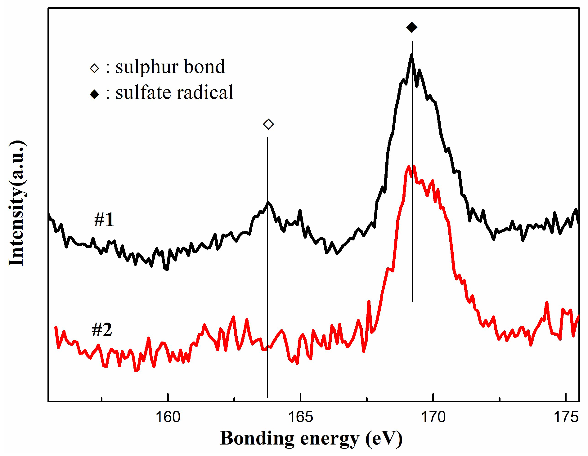
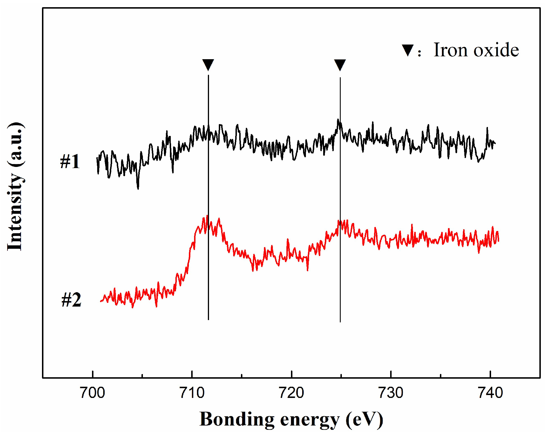
3.4. X-Ray Photoelectron Spectroscopy

In order to investigate the chemical structure differences between sample #1 and sample #2, XPS analysis was performed. The iron and sulfur spectra are shown in Figure 8 and Figure 9, respectively.
As seen in Figure 8, sample curve #1 showed the characteristic peak of sulfur in monosulfide and disulfide bonds at 164 eV [30]. The peak was absent in sample curve #2, indicating that the rubber in the brake shoe degraded after braking, which led to the disappearance of sulfur bonds. This result was consistent with the TG and DTG results. Moreover, both the samples showed the characteristic peak of sulfur in barium sulfate near 169 eV [30].
As observed in Figure 9, sample curve #2 showed the characteristic peaks of iron oxide at 712 and 725 eV. The peaks of elemental iron typically appear at 720 and 706 eV [30]; moreover, the peak at 706 eV has a significantly higher intensity than that at 720 eV. Sample #2 did not exhibit these peaks, confirming that sample #2 did not contain elemental iron; this indicated that the iron from the wheel was oxidized to form iron oxide. Notably, sparks were seen during the braking process, suggesting that the surface temperature was considerably high.

3.5. Raman Spectra

In order to understand the microstructural differences between samples #1 and #2, the two samples were analyzed by Raman spectroscopy. The Raman spectrum curves are shown in the Figure 10.
As shown in Figure 10,there were two strong peaks in each sample. These were the D peak and G peak of graphite, respectively, which were aligned with the vibrational modes of the D band, caused by structural defects, and the G band, caused by the stretching of the in-plane C atom [31]. The D peak of sample #2 was stronger than that of sample #1. The strength of the D peak was related to the degree of distortion of the graphite lattice. The greater the distortions, the stronger the peak. The characteristics of the peak were also related to the graphite particle size. The smaller the particles, the higher the peak [32]. The D peak strength of sample #2 was significantly enhanced. The D peak and G peak intensity ratios (ID/IG) for sample #1 and sample #2 were 0.38 and 0.84, respectively. The finer the graphite particles and the greater the internal distortions, the higher the ID/IG ratio [31,32]. The results indicated that sample #2 contained finer graphite particles and more internal distortions than sample #1. There were minor differences in the positions of the peaks of the two samples. The D peak of sample #1 was at 1350 cm−1, and that of sample #2 was at 1344 cm−1, with a difference of 6 cm−1. The G peak of sample #1 was at 1582 cm−1, and that of sample #2 was at 1589 cm−1, with a difference of 7 cm−1. These differences were due to the particle sizes of the two samples, with sample #2 containing smaller particles than sample #1 [33]. In conclusion, we determined that the graphite in sample #2 was broken down by the huge shear force during the braking process. The graphite became finer, and the crystalline structure was also destroyed.

3.6. X-Ray Diffraction

In order to investigate the differences in the inorganic filler structure between samples #1 and #2, the two samples were analyzed by XRD; the patterns are shown in Figure 11.
Compared to sample #1, sample #2 showed significantly stronger peaks at 27.6°, 31.0°, and 44.7°. These peaks were assigned to iron oxide [34]. This indicated that the content of iron oxide increased considerably after braking. Notably, the intensities of the peaks at 26.8° and 54.8° for sample #2 were lower than those for sample #1. These peaks were assigned to graphite [35,36]. In addition, the intensities of the three peaks at 28.8°, 42.6°, and 42.9° were lower for sample #2. These peaks were assigned to barium sulfate [37]. The results indicated that during the friction process, the filler materials, such as graphite and barium sulfate, were broken down. As a result, the crystal structures were destroyed, leading to the weakening of the diffraction peaks. Moreover, the content of filler particles decreased in the third body. This was consistent with the previous XRF results. Notably, new peaks were observed at 11.7° and 13.7° for sample #2. This indicated that new crystal structures were formed during the friction process. In conclusion, after braking, the crystalline structures of inorganic substances such as graphite and barium sulfate were destroyed, leading to a reduction in the overall crystallinity. Furthermore, some new crystalline structures were formed in the third body.

4. Conclusions

In this study, an organic composite railway brake shoe was subject to a braking test at an initial braking speed of 125 km/h using a full-scale dynamometer. Next, the surface morphology and composition of the third body formed during the test were comprehensively analyzed. The major conclusions drawn from the results are discussed below.
The morphology of the third body: The upper surface of the third body was smooth, and the lower surface was rough. The structural density of the portion closer to the upper surface was relatively high. Moreover, the cross-sectional image of the third body showed that it had a layered structure, indicating that it was formed via the accumulation of particles and layer-by-layer rolling.
The composition of the third body: During the braking test, most of the rubber was degraded. In addition, the third body contained relatively low amounts of sulfur and carbon. However, the iron content in the third body was significantly higher than that in the organic composite railway brake shoe. Moreover, the upper surface of the third body had a significantly higher iron content than the lower surface. The iron mostly existed in the form of iron oxide. The reduction in the amounts of barium, calcium, silicon, sulfur, potassium, and zinc was attributed to thermal degradation or friction. Notably, the loss ratios were different. Components of the brake shoe such as graphite, feldspar, and barium sulfate were found to be crushed in the third body. Furthermore, some inorganic materials were decomposed, and the crystal structures were changed; nonetheless, new crystal structures were formed.
The formation process of the third body: The formation of the third body was mainly affected by force and heat. The force between the organic composite railway brake shoe and the wheel caused wear. As a result, the debris was broken down and squeezed. The debris particles then accumulated on the surface of the organic composite railway brake shoe, forming a third body. In the early stage of friction, the brake shoe had a low compression modulus and a high wear rate. The surface of the organic composite railway brake shoe was mainly covered with the brake shoe residue and some iron scraps. As the surface of the organic composite railway brake shoe was mostly covered with grinding chips, the conditions of the contact with the wheel changed. The third body was mainly composed of inorganic matter and iron filings. The wear of the wheel as well as the amount of iron debris increased as the friction process progressed. An increase in the iron content led to an increase in the mechanical strength of the third body. The friction between the organic composite railway brake shoe and the wheel caused most of the rubber to degrade and the filler to break, leading to changes in the crystal structure. It also led to the oxidation of the iron shed from the wheel.

Author Contributions

Conceptualization, material preparation, data curation, and methodology: C.H. Investigation, data curation, and formal analysis: Y.J. Resources, funding acquisition, and project administration: D.P. Writing (original draft): M.G. Validation and visualization: C.C. Supervision: J.Z. Writing (review and editing): W.W. All authors have read and agreed to the published version of the manuscript.

Funding

This work was supported by the China Academy of Railway Sciences Corporation Limited Fund Project (Grant No. 2021YJ225).

Institutional Review Board Statement

Not applicable.

Informed Consent Statement

Not applicable.

Data Availability Statement

Data will be made available on request.

Acknowledgments

The authors extend their appreciation to the China Academy of Railway Sciences Corporation Limited for funding this work.

Conflicts of Interest

The authors declare no conflict of interest.

References

  1. Hui, Y.; Liu, G.M.; Du, J.H.; Zhang, B.S. Research Progress on Friction and Wear Behavior of Brake Materials Based on the Third Body. Cailiao Daobao 2021, 35, 19153–19160. [Google Scholar] [CrossRef]
  2. Shen, M.X.; Rong, K.J.; Xiong, G.Y.; Zhu, M.H. Research Progress on the Low Adhesion Behavior between Wheel and Rail Interface Induced by Third-Body Medium. Mater. Rep. 2021, 35, 13160–13167. [Google Scholar] [CrossRef]
  3. Khan, S.A.; Lundberg, J.; Stenström, C. The effect of third bodies on wear and friction at the wheel-rail interface. Proc. Inst. Mech. Eng. Part F J. Rail Rapid Transit 2022, 236, 662–671. [Google Scholar] [CrossRef]
  4. Chen, K.; Lu, Z.; Wei, P.; Liu, H.; Wei, D.; Xie, H. Study of Friction and Wear Characteristics of PEEK by Reciprocating Sliding Experiment and Temperature Dependences Simulation. Tribol. Lett. 2022, 70, 99. [Google Scholar] [CrossRef]
  5. Fan, J.; Wang, W.; Wang, H.; Pu, J. Tribological Performance and Mechanism of MoN/VN Multilayer Films with Different Modulation Periods at Different Temperature. Tribol. Lett. 2021, 69, 54. [Google Scholar] [CrossRef]
  6. Ren, X.; Zhang, G.; Xu, H.; Wang, Z.; Liu, Y. Wear Resistance Mechanism of Sub-Nano Cu3P Phase Enhanced the Cu-Pb-Sn Alloy. Coatings 2022, 12, 682. [Google Scholar] [CrossRef]
  7. Shpenev, A.G.; Muravyeva, T.I.; Shkalei, I.V.; Bukovskiy, P.O. Influence of the Surface Film (Third Body) on the Friction Wear Process of Carbon-Fiber Composites. J. Surf. Invest. 2022, 16, 397–401. [Google Scholar] [CrossRef]
  8. Zhu, Y. The influence of iron oxides on wheel–rail contact: A literature review. Proc. Inst. Mech. Eng. Part F J. Rail Rapid Transit 2018, 232, 734–743. [Google Scholar] [CrossRef]
  9. Yang, Z.Y.; Wang, Z.M.; Wang, J.L.; Li, Z.Q.; Liu, X.L. Tribological Properties of SiCp/A356 Composites Against Semimetallic Materials under Dry and Wet Conditions. J. Mater. Eng. Perform. 2021, 30, 4148–4161. [Google Scholar] [CrossRef]
  10. Su, L.L.; Gao, F.; Wang, L.X.; Han, X.M.; Fu, R.; Tao, H.L. Iron Powder Third Body Contribution to Friction Performance of Copper-Matrix Friction Composites. Tribol. Trans. 2019, 62, 1576956. [Google Scholar] [CrossRef]
  11. Makni, F.; Cristol, A.L.; Elleuch, R.; Desplanques, Y. Organic Brake Friction Composite Materials: Impact of Mixing Duration on Microstructure, Properties, Tribological Behavior and Wear Resistance. Polymers 2022, 14, 1692. [Google Scholar] [CrossRef] [PubMed]
  12. Yang, C.; Yan, H.; Chen, Q.; Liu, Y.; Zhang, N. On the Impact of Surface Morphology and Transfer Film on Brake System Performance of High-Capacity Metro Train. Coatings 2022, 12, 894. [Google Scholar] [CrossRef]
  13. Verma, P.C.; Ciudin, R.; Bonfanti, A.; Aswath, P.; Straffelini, G.; Gialanella, S. Role of the friction layer in the high-temperature pin-on-disc study of a brake material. Wear 2016, 346–347, 56–65. [Google Scholar] [CrossRef]
  14. Meierhofer, A.; Hardwick, C.; Lewis, R.; Six, K.; Dietmaier, P. Third body layer—Experimental results and a model describing its influence on the traction coefficient. Wear 2014, 314, 148–154. [Google Scholar] [CrossRef]
  15. Ghosh, P.; Banerjee, S.S.; Khastgir, D. Elastomer modified phenolic resin-based composites with reduced scale friction: Influ-ence of calcined petroleum coke on tribological and thermo-mechanical behavior. Polym. Eng. Sci. 2020, 60, 1446–1458. [Google Scholar] [CrossRef]
  16. Saga, S.; Karino, Y.; Haga, A.; Nakahashi, J.I. Development of composition brake shoe for reducing heat load to wheel tread with keeping brake performance. Q. Rep. RTRI 2014, 55, 7–13. [Google Scholar] [CrossRef]
  17. Pei, D.F.; Zhang, G.W.; Dang, J.; He, C.J. Study on the formulation and technology of the new composite brake shoes with high-friction coefficient. China Railw. Sci. 2012, 32, 91–94. [Google Scholar]
  18. Pei, D.F.; Zhang, G.W.; Dang, J.; He, C.J. Development of composite brake shoes with high friction coefficient for high power diesel locomotive (HXN). China Railw. Sci. 2012, 33, 135–139. [Google Scholar]
  19. Ilie, F.; Cristescu, A.-C. Tribological Behavior of Friction Materials of a Disk-Brake Pad Braking System Affected by Structural Changes—A Review. Materials 2022, 15, 4745. [Google Scholar] [CrossRef]
  20. Yin, T.; Fu, Q.G.; Zhou, L.; Fu, Y.W. Powdered nitrile rubber @ silicon dioxide capsule as the wear modifier of phenolic resin composites under dry friction. Tribol. Int. 2020, 151, 106517. [Google Scholar] [CrossRef]
  21. Yin, T.; Fu, Q.G.; Zhou, L.; Fu, Y.W. Superior wear resistance of boron phenolic resin-based composites using fluorine rubber micro powder as high-performance additive. Tribol. Int. 2020, 151, 106001. [Google Scholar] [CrossRef]
  22. Ghosh, P.; Ghosh, D.; Kumar Chaki, T.; Khastgir, D. NBR Powder Modified Phenolic Resin Composite: Influence of Graphite on Tribological and Thermal Properties. Tribol. Trans. 2017, 60, 548–556. [Google Scholar] [CrossRef]
  23. Monreal, P.; Harrison, N.; Perez-Costarrosa, E.; Zugasti, M.; Madariaga, A.; Claveria, I. Full-Scale Dynamometer Tests of Composite Railway Brake Shoes: Effect of the Resin-Rubber Ratio on Friction Performance and Wear. J. Tribol. 2022, 144, 454061704. [Google Scholar] [CrossRef]
  24. Zhou, S.X.; Bai, X.Y.; Pei, D.F.; Sun, Y.D.; Yang, W.C. Research on the Metal Mosaic Behavior of Train Braking Based on Microscale. J. Mech. Eng. 2021, 57, 210–218. [Google Scholar]
  25. Abdel-Latif, M.M.A.; El-Tayeb, N.S.M.; Mahale, V.; Bijwe, J. The effect of wollastonite silane-treatment on mechanical and tribological performance of NAO brake-pads. Int. J. Surf. Sci. Eng. 2019, 13, 293–316. [Google Scholar] [CrossRef]
  26. Liu, L.; Wang, B.X.; Qu, Y.T.; Zhang, B.G.; Yang, H. Factors Influencing Thermal Degradation of NBR. China Rubber Ind. 2013, 60, 211–215. [Google Scholar]
  27. Ozen, I.; Simsek, S.; Eren, F. Production and Characterization of Polyethylene/Calcium Carbonate Composite Materials by Using Calcium Carbonate Dry and Wet Coated with Different Fatty Acids. Polym. Polym. Compos. 2013, 21, 183–187. [Google Scholar] [CrossRef]
  28. Murakami, T.; Nishimura, T.; Tsuda, N.; Kasai, E. Quantitative Analysis on Contribution of Direct Reduction of Iron Oxide in Carbon Composite. ISIJ Int. 2013, 53, 1763–1769. [Google Scholar] [CrossRef]
  29. Ghosh, A. Kinetics of Reduction of Iron Oxide in Mixtures of Oxide and Carbon: A Critical Appraisal. Trans. Indian Inst. Met. 2013, 66, 71–77. [Google Scholar] [CrossRef]
  30. Wagner, C.D.; Riggs, W.M.; Davis, L.E.; Moulder, J.F.; Muilenberg, G.E. Handbook of X-ray Photoelectron Spectroscopy; Perkin-Elmer Corporation: Saint Paul, MN, USA, 1979; pp. 56–78. [Google Scholar]
  31. Saberi, A.; Bakhsheshi-Rad, H.R.; Ismail, A.F.; Sharif, S.; Razzaghi, M.; Ramakrishna, S.; Berto, F. The Effect of Co-Encapsulated GO-Cu Nanofillers on Mechanical Properties, Cell Response, and Antibacterial Activities of Mg-Zn Composite. Metals 2022, 12, 47207. [Google Scholar] [CrossRef]
  32. Li, H.T.; Cao, D.Y.; Zhang, W.G.; Wang, L. XRD and Raman Spectroscopy Characterization of Graphitization Trajectories of High-Rank Coal. Spectrosc. Spectr. Anal. 2021, 41, 2491–2498. [Google Scholar]
  33. Wu, R.L.; Shao, Z.Z.; Chang, S.L.; Zhang, X.A.; Li, H.P.; Li, X.H. Study on Raman spectra of multi-walled carbon nanotubes with different parameters. Spectrosc. Spectr. Anal. 2014, 34, 982–985. [Google Scholar]
  34. Rajeev, R.; Suraj, S.; Catherine, K.B.; Ninan, K.N. Synthesis of nano grade alpha-ferric oxide and evaluation of its catalytic properties. Int. J. Nanotechnol. 2012, 8, 916–924. [Google Scholar] [CrossRef]
  35. Bychko, I.; Abakumov, A.; Didenko, O.; Chen, M.Y.; Tang, J.G.; Strizhak, P. Differences in the structure and functionalities of graphene oxide and reduced graphene oxide obtained from graphite with various degrees of graphitization. J. Phys. Chem. Solids 2022, 164, 110614. [Google Scholar] [CrossRef]
  36. Muzyka, R.; Díez, N.; Gryglewicz, G. Oxidation of graphite by different modified Hummers methods. New Carbon Mater. 2017, 32, 15–20. [Google Scholar] [CrossRef]
  37. Liu, Y.J.; Guo, X.Y.; Yang, S.H.; He, G.X.; Jin, H.B. Controllable Preparation of Uniform Micron-Sized Barium-Sulfate Spheres. Cryst. Res. Technol. 2018, 53, 1700212. [Google Scholar] [CrossRef]
Figure 1. Full-scale railway dynamometer.
Coatings 13 00952 g001
Figure 2. Digital photos of brake shoe and schematic diagram for the location of the samples.
Coatings 13 00952 g002
Figure 3. Optical images of the third body: (a) the upper surface, (b) the lower surface.
Coatings 13 00952 g003
Figure 4. SEM images of the third body: (a) the upper surface, (b) the lower surface.
Coatings 13 00952 g004
Figure 5. Cross-sectional SEM image of the third body.
Coatings 13 00952 g005
Figure 6. EDS curves of the third body: (a) the upper surface of the third body, (b) the lower surface of the third body.
Coatings 13 00952 g006
Figure 7. TG (A) and DTG (B) curves of samples #1 and #2.
Coatings 13 00952 g007
Figure 8. Sulfur XPS curves for samples #1 and #2.
Coatings 13 00952 g008
Figure 9. Iron oxide XPS curves for samples #1 and #2.
Coatings 13 00952 g009
Figure 10. Raman spectra of samples #1 and #2.
Coatings 13 00952 g010
Figure 11. XRD patterns of samples #1 and #2.
Coatings 13 00952 g011
Table 1. EDS analysis results from Figure 6 (wt%).
SpotCarbonOxygenBariumCalciumIronSiliconSulfur
a3.2530.6515.493.8831.877.873.66
b10.1640.9512.964.592.4820.793.43
Table 2. Elemental content of samples.
Elemental Content (wt%)BariumCalciumIronSiliconSulfurPotassiumZinc
Sample #138.4221.8511.5512.126.604.360.61
Sample #225.3810.5743.068.115.713.300.43
C (%)−33.94−51.62272.81−33.09−13.48−24.31−29.51
Disclaimer/Publisher’s Note: The statements, opinions and data contained in all publications are solely those of the individual author(s) and contributor(s) and not of MDPI and/or the editor(s). MDPI and/or the editor(s) disclaim responsibility for any injury to people or property resulting from any ideas, methods, instructions or products referred to in the content.

