Article

Characteristics and Cutting Performance of CVD Al2O3 Multilayer Coatings Deposited on Tungsten Carbide Cutting Inserts in Turning of 24CrMoV5-1 Steel

by
Maoxiang Zhu
1,2,3,*,
Soufyane Achache
1,2,
Mariane Prado Motta
4,
Alexandre Delblouwe
1,
Cyril Pelaingre
4,
Alexis Carlos García-Wong
3,
Jean-François Pierson
3 and
Frédéric Sanchette
1,2
1
LASMIS, Université de Technologie de Troyes, Antenne de Nogent, Póle Technologique de Sud Champagne, 52800 Nogent, France
2
Nogent International Centre for Coating Innovation, LRC CEA-LASMIS, UTT, Antenne de Nogent, Póle Technologique de Sud Champagne, 52800 Nogent, France
3
Institut Jean Lamour, UMR CNRS 7198, Université de Lorraine, 54000 Nancy, France
4
CIRTES SA, 88100 Saint-Dié-des-Vosges, France
*
Author to whom correspondence should be addressed.
Coatings 2023, 13(5), 883; https://doi.org/10.3390/coatings13050883
Submission received: 16 April 2023 / Revised: 3 May 2023 / Accepted: 5 May 2023 / Published: 8 May 2023
(This article belongs to the Special Issue Ceramic Films and Coatings: Properties and Applications)

Abstract

:
In this work, TiN/Ti(C,N)/Al2O3 multilayer coatings were deposited using an industrial-scale thermal CVD system. Two polymorphs of Al2O3, the stable α- and the metastable κ-Al2O3, were obtained by the deposition of specific bonding layers at the Al2O3/Ti(C,N) interface. The comparable hardness and elastic moduli of α- and κ-Al2O3 multilayer coatings were measured. The tribological behavior of Al2O3 multilayer coatings was studied at room temperature using 24CrMoV5-1 balls; friction coefficients were comparable for both α- and κ-Al2O3 multilayer coatings. As a result of the relatively high hardness of coatings and the generation of abrasive wear particles, larger wear tracks were observed on balls. In Rockwell C tests, good adhesion at Al2O3/Ti(C,N)-based layer’s interface was reported in κ-Al2O3 multilayer coatings, which could be attributed to the deposition of κ-bonding layers consisting of needle-shaped grains. The cutting performances in the turning-roughing of 24CrMoV5-1 steel under different parameters—cutting speed, feed, and depth of cut—were investigated. Herein, κ-Al2O3 multilayer coatings showed the longest tool life, double of that of a commercial CVD Al2O3 multilayer coating. The results obtained could enrich the existing database for the development of prediction models of tool wear and machined surface quality and help improve tool performance for the machining of 24CrMoV5-1 steel.

1. Introduction

Metal cutting is a manufacturing process achieved through different operations, mainly categorized as turning, milling, and drilling [1]. During metal cutting, high forces act at contact zones between the tool and workpiece. The chip formation involves the plastic deformation at shear zones, generating contact stress and heat in cutting tools, which are subjected to abrasive and adhesive wear. When using workpiece materials with relatively high thermal conductivities, the generated heat is transported away with chip flow over the tool rake face [2,3,4,5]. In the case of continuous cylindrical turning, the workpiece rotates around its center axis, while a sharp-edged tool is set to a certain depth of cut for performing a facing operation towards the workpiece rotational center [6]. In contact zones, high temperatures are reached, where thick coatings (≈5–20 µm) with low thermal conductivities are accepted as favorable since they provide a thermal barrier to the substrate, and the generated heat is deflected into the chip, preventing the plastic deformation of the underlying substrate [1,7].
CVD α- and κ-Al2O3 coatings were found to be efficient to protect cutting tools from crater wear on the rake face, due to their low adhesion tendency in contact with metals and excellent chemical stability at high temperatures [8]. α- and κ-Al2O3 differ in their crystal structure, grain size and thermal conductivity; the low thermal conductivity of κ- Al2O3, approx. three times lower than α-Al2O3, suggests that this metastable phase of alumina could be an excellent thermal barrier for cutting tools [9]. However, κ-Al2O3 can transform irreversibly to α-Al2O3 at high temperatures, resulting in a volume contraction of approx. 8% due to the heat generated during thermal CVD process and metal cutting [10]. It was also reported that the mechanical properties of CVD α-Al2O3 coatings could be enhanced by choosing an optimized texture for the α-Al2O3 phase [11]. Consequently, CVD Al2O3 coatings have continuously been optimized with respect to the phase and film texture control.
In previous studies, CVD TiN/Ti(C,N)/Al2O3 multilayer coatings were extensively studied [12,13]. It was shown that the growth of α- and κ-Al2O3 on Ti(C,N) could be controlled with the deposition of bonding layers at the Al2O3/Ti(C,N)-based layer’s interface [12]. The epitaxial growth of α-Al2O3 on rutile as well as that of κ-Al2O3 on needle-like Ti(C,N) were reported [12,13]. It is essential to achieve the phase control to compare the performance of CVD α- and κ-Al2O3 multilayer coatings in the present work.
In this work, 24CrMoV5-1 was selected as the workpiece material, which is widely used to produce molds for light metals and plastics. Based on a previous study, tungsten carbide tools with coatings of hard refractory materials such as Ti(C,N) and Al2O3 were used for turning operations of 24CrMoV5-1 steel herein [14]. The aim of the present work is to study mechanical and tribologicial properties of CVD α- and κ-Al2O3 multilayer coatings and to investigate the effects of operational conditions on tool wear. The cutting performances of coated tungsten carbide inserts were characterized and compared to that of a commercial CVD Al2O3 multilayer coating.

2. Materials and Methods

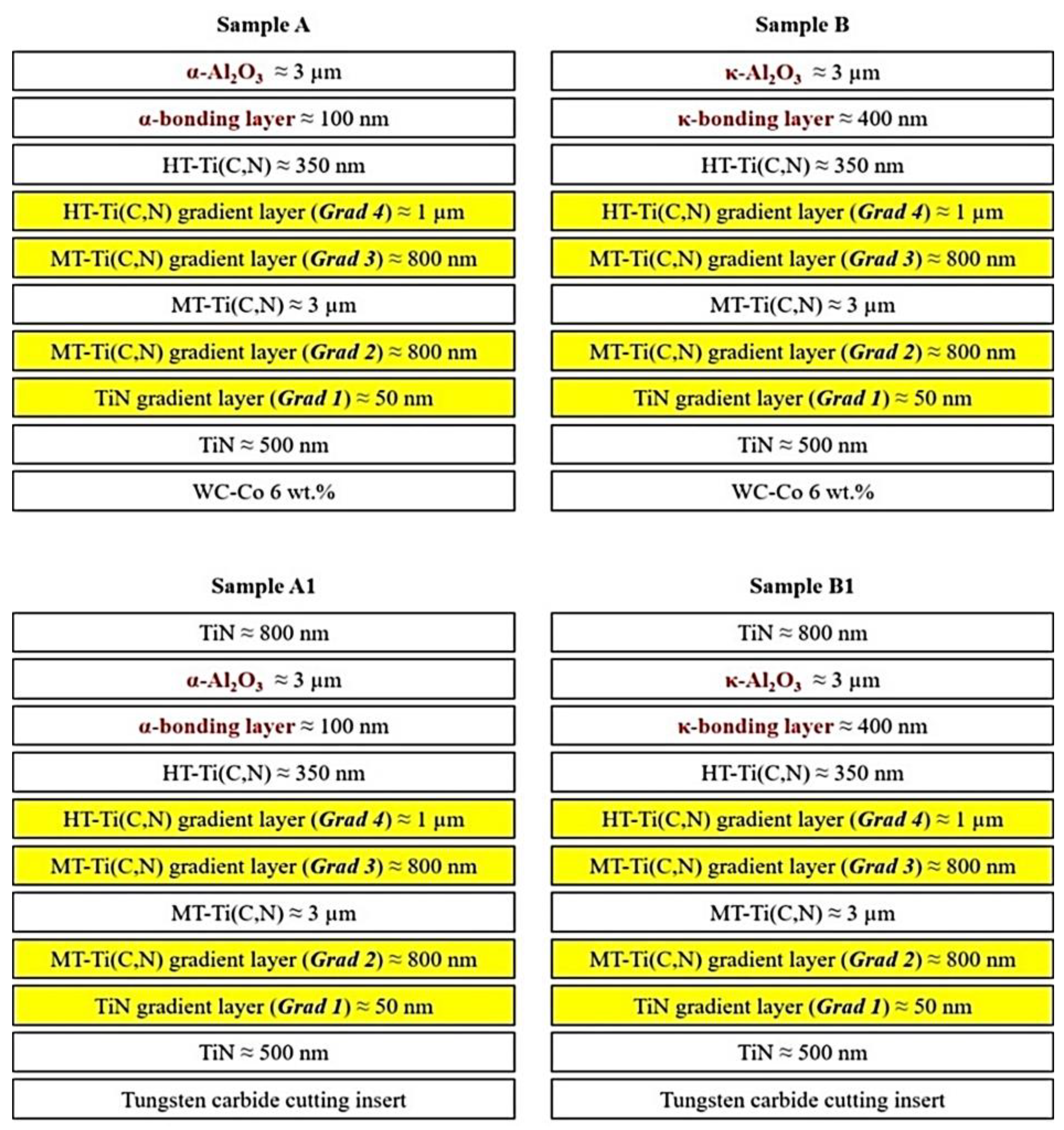
2.1. Sample Preparation

Four CVD Al2O3 multilayer coatings were deposited, corresponding to the following samples: A, B, A1 and B1. All coatings were deposited using an industrial-scale thermal CVD system (Ionbond BernexTM BPXpro 325S, IHI group, Olten, Switzerland). The process was described in a previous study, principally composed of four systems: reactor, AlCl3 generator, by-products treatment system, gaseous and liquid precursors (TiCl4 and CH3CN) supply systems [15]. As shown in Figure 1, the multilayers in samples A and B were deposited on 30 mm diameter cemented carbide substrates (WC-Co 6 wt.%) to study the mechanical and tribological properties of CVD Al2O3 coatings. All substrates were mirror-polished (1μm diamond slurry) and cleaned using ethanol.
This coating architecture is described as: TiN buffer layer/TiN gradient layer (Grad 1)/MT-Ti(C,N); gradient layer (Grad 2)/MT-Ti(C,N)/MT-Ti(C,N); gradient layer (Grad 3)/HT-Ti(C,N); gradient layer (Grad 4)/HT-Ti(C,N); and α- or κ-bonding layer/Al2O3. For clarity, the TiN buffer layer acts as a diffusion barrier of Co from the substrate, Ti(C,N) layers provide high hardness and good wear resistance; bonding layers help to control the growth of α- and κ-Al2O3 on Ti(C,N); and the Al2O3 top layer can improve the oxidation resistance of coatings. Herein, α-Al2O3 was obtained in samples A and A1, whereas κ-Al2O3 was obtained in samples B and B1. Importantly, multilayers with a 0.8 µm thick TiN top layer were deposited in samples A1 and B1 on tungsten carbide inserts for the turning of 24CrMoV5-1 steel. TiN top layers can facilitate the wear detection. TiN top layers in samples A1 and B1 were deposited at 1005 °C and 70 mbar from a TiCl4-H2-N2 gas mixture (H2: balance, N2: 39.4 vol.%, TiCl4: 1.70 vol.%, the total flow rate: 34.0 L.min−1). Due to an increasing deposition temperature in the CVD process, MT (medium-temperature) and HT (high-temperature) Ti(C,N) layers, as well as different gradient layers, were deposited in order to enhance the process continuity and the coating adhesion. The detailed deposition parameters are given in Table 1 and Table 2.

2.2. Characterization

X-ray diffraction (XRD) studies were carried out using a Bruker D8 Advance diffractometer (Bruker, Billerica, MA, USA) operating at 40 kV/40 mA with Kα radiation of Cu (λ Kα1 = 1.54059 Å and λ Kα2 = 1.54443 Å). Phase identifications were conducted in Bragg–Brentano geometry with a step size of 0.02° for a 2θ-range from 20° to 60°. Peak positions were determined by fitting the diffraction peaks with the Pseudo–Voigt function, and the software MAUD (version 2.92) was used. The instrumental contribution was determined using the standard material® 640d.
Surface morphology was observed using a Zeiss Gemini 500 scanning electron microscope (SEM, Jena, Germany), and cross-sectional fractures were prepared by a FIB/SEM FEI Helios NanoLab 600i (FEI, Hillsboro, OR, USA) equipped with platinum gas injection system. The FIB column used a gallium liquid metal ion source operating at an accelerating voltage up to 30 kV. A Pt-layer was primarily deposited to protect the coating surface from ion beam damage. However, the film thickness is more than 11 µm, which exceeds the limit of the FIB/SEM used, and only the Al2O3 and Ti(C,N)-based layer’s interface was highlighted.
The average surface roughness Ra was evaluated by an AltiSurf© 500 optical profilometer (Altimet, Thonon-Les-Bains, Switzerland) with a scanning rate of 50 μm/s, using a measurement length of 5 mm on ten different positions at the coating surface. Surface profiles were characterized after ball-on-disc tests with a scanning rate of 50 μm/s (analyzed area: 2.5 × 2.5 mm2).
The hardness and modulus of samples A and B were evaluated by a Nano-indenter HYSITRON TI980 using a Berkovitch diamond tip with a maximum load of 11 mN. Loading and unloading rates were 2 mN/s with a residence time of 2 s at the maximum load. Prior to measurements, the coating surface was mirror-polished to eliminate asperities and to obtain an average roughness Ra less than 15 nm. Twenty-five indentations were performed for each sample and an average value was considered. The Oliver and Pharr method and the Poisson’s ratio of 0.24 for both α- and κ-Al2O3 were used for calculations [16,17]. Vickers hardness HV0.05 values were measured using a Wilson® TUKONTM 1202 (Buehler, Leinfelden-Echtergingen, Germany): ten indentations were performed for each sample, and an average value was considered [18].
A CSM tribometer was used for ball-on-disc tests. Samples A and B were tested using 6 mm diameter grade 24CrMoV5-1 balls (workpiece material for cutting tests) without lubricant. A normal force of 10 N (maximum of the tribometer used) was applied; the sliding distance was 1000 m with a speed of 10 cm/s and a rotational radius of 2.5 mm. Wear tracks on coating surfaces were observed by an optical microscope KEYENCE VH-Z250R (KEYENCE, Bois-Colombes, France). Rockwell C tests were carried out for samples A and B to investigate the film adhesion and its brittleness; a conical diamond indenter with a load of 150 kg was used [19].
Furthermore, Ø 200 × 300 mm annealed bars of 24CrMoV5-1 (Dijon, France: ANFOR NFA) with a hardness of 220 HB were selected as the workpiece material; its composition (C: 0.39 wt.%, Si: 1.03 wt.%, Mn: 0.33 wt.%, Cr: 5.07 wt.%, Ni: 0.16 wt.%, Mo: 1.23 wt.%, V: 0.39 wt.%, P: 0.02 wt.% and S: <0.001 wt.%) is given in a previous study [14]. The tool holder DCLNL 3232 P16 was used with uncoated (CNMX 16 06 12 E8 CH01) and coated (CNMX 16 06 E8 CFX 1025) inserts provided by Evatec Tools. According to the ISO standard 3002:1982, the tool cutting edge angle (kr) is 95°, the tool cutting edge inclination (λs) is −6°, the orientation of the cutting face (γo) is −6° and the orientation of the flank (αo) is 6°.
A spinner TC600 CNC lathe machine was used for the cylindrical turning of 24CrMoV5-1 steel; the experimental set-up is shown in Figure 2 [14]. A water–oil mixture (8.5% S-Aero Fluch soluble oil) was used as lubricant during turning. Cutting edge temperatures were measured by an Actarus® System (CIRTES, Saint-Dié-des-Vosges, France); a temperature probe was 1 mm under the cutting edge. A triaxial piezoelectric dynamometer-Kistler 9257B and accelerometer-Kistle 8763B were placed to measure cutting forces and accelerations in feed, in tangential and radial directions with reference to tools [14,20]. Herein, cutting parameters, cutting forces, accelerations, and temperature are inputs of the ‘‘Machine Learning Model’’, which can provide an estimation of tool wear and machined surface roughness as outputs [14].
The COM (Couple Tool-Material) protocol defined on the standard NF E 66-520 was devoted to the determination of cutting parameters, for a precise association of tool, workpiece material and machining operation. This protocol provides the guidelines for choosing minimum values for cutting speed-Vc, as well as maximum and minimum values of depth of cut-ap and feed-f. The determination of these values is based on cutting parameters and other process information (cutting forces, accelerations, cutting edge temperatures, roughness of the machined surface, tool wear, chip shape, etc.).
Herein, 39 experiments were carried out following the COM protocol using commercial coated inserts from Evatec Tools to choose the optimum cutting parameters. As can be seen in Table 3, cutting speed-Vc was increased from 150 to 500 m/min in the series (A), feed-f was increased from 0.2 to 0.6 mm/rev in the series (B), and depth of cut-ap was increased from 1 to 5.5 mm in the series (C). These parameters (Vc: 150–500 m/min, f: 0.2–0.6 mm/rev and ap: 1–5.5 mm) were suggested by Evatec Tools for turning-roughing operations.
Each experiment repeated three times consists of performing a cylindrical turning operation for about 30 s with given cutting parameters, to obtain stable signals of temperature and a visible evolution of tool wear. Accelerations and cutting-edge temperatures were measured, and specific cutting force-kc (cutting force per unit area of cut) was calculated according to the standard NF ISO 3002-4. Tool flank wear-Vb was measured as the average width of the flank land by an optical microscope according to the ISO standard 3685:1993. At the end of each experiment, an average roughness Ra of the machined surface was measured by a portable roughness tester: Mitutoyo SJ 210 (Mitutoyo, Roissy, France). A new cutting edge was used for each experiment.
Based on the results obtained from 39 experiments and the “Machine Learning Model”, cutting parameters were determined: cutting speed—240 (m/min), feed—0.35 (mm/rev) and depth of cut—3.5 (mm). In these conditions, a low flank wear with a low machined surface roughness was obtained for turning of 24CrMoV5-1 steel using commercial coated cutting inserts (CNMX 16 06 E8 CFX 1025) from Evatec Tools (Evatec tools, Thionville, France). However, it was not possible to characterize this TiN/TiB2/Al2O3 commercial coating in terms of coating thickness, composition or microstructure. Afterwards, tool-life tests were carried out according to the ISO standard 3685:1993 using these determined parameters. When tool flank wear-Vb reached 300 µm or edge breakage occurred, the cutting edge was considered as reaching the end of life. The results obtained are discussed in Section 3.5.

3. Results and Discussion

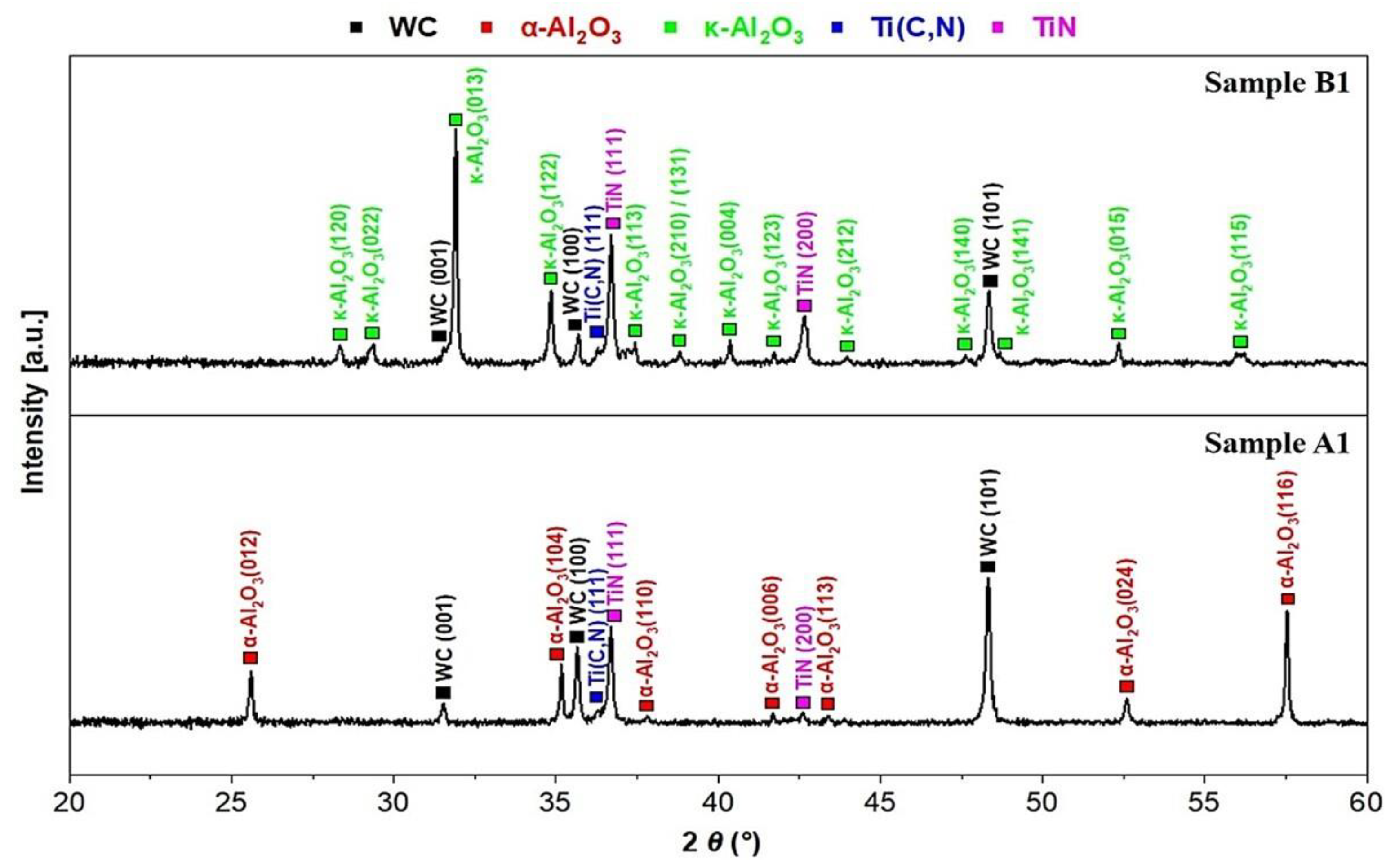
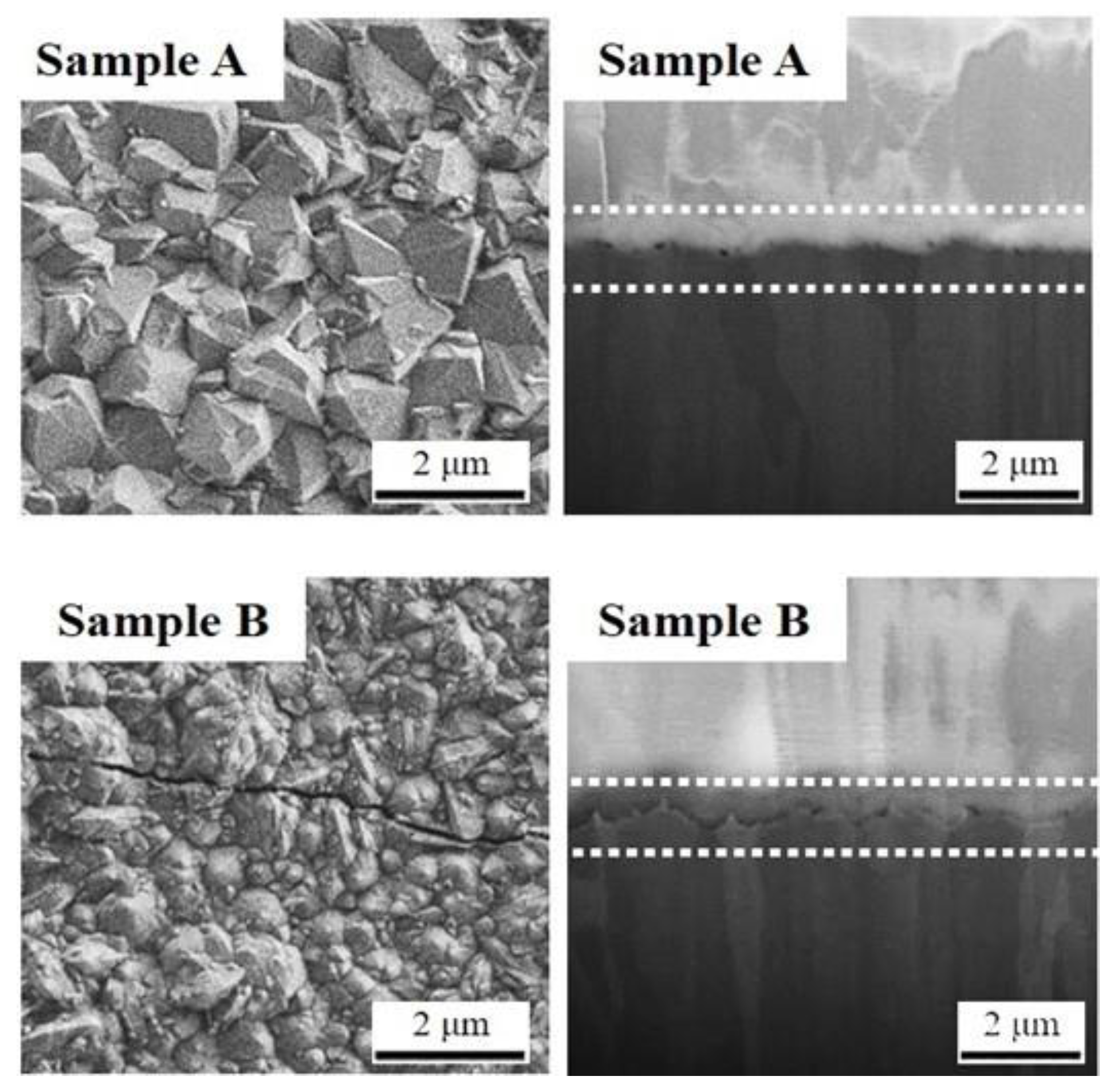
3.1. Structure, Morphology and Microstructure Analyses

The X-ray diffractograms of samples A, A1, B and B1 are presented in Figure 3 and Figure 4. It is shown that α-Al2O3 was obtained in samples A and A1, due to the deposition of the α-bonding layer that was obtained by oxidizing the uppermost part of the HT-Ti(C,N) layers. This oxidizing step resulted in the formation of rutile; the epitaxial growth of α-Al2O3 on rutile was evidenced [12]. On the contrary, κ-Al2O3 was obtained in samples B and B1, due to the deposition of κ-bonding layer composed of Ti(C,N) needle-shaped grains [12]. Compared with Figure 3, diffraction peaks belonging to TiN were pronounced in Figure 4, since 800 nm thick TiN top layers were deposited in both samples A1 and B1 to facilitate the wear detection after the manufacturing process.
Figure 5 shows surface morphologies and cross-sectional microstructures of samples A and B. Sample A consists of facetted grains, in agreement with earlier observations reported [12,21,22]. Previous studies found that κ- to α-Al2O3 phase transformation can occur during the CVD deposition process, and α-Al2O3 obtained through this phase transformation shows large equiaxed grains [21,23]. Herein, neither diffraction peaks originating from κ-Al2O3, nor large equiaxed grains was observed, and the phase transformation is ruled out. In contrast, sample B is composed of small, rounded grains, thus a similar morphology was reported [12]. Some cracks were observed due to thermal stresses generally found in CVD coatings. Cross-sectional fractures were prepared by FIB, the Al2O3 and Ti(C,N)-based layer’s interface was highlighted, and Ti(C,N) needle-shaped grains were grown to promote the nucleation of κ-Al2O3 in sample B.

3.2. Nano- and Micro-Indentation

The hardness of 28.0 ± 0.8 GPa and 25.6 ± 0.4 GPa was measured for samples A and B, in good agreement with earlier studies: polycrystalline α-Al2O3 exhibits slightly higher hardness than κ-Al2O3 [24,25,26,27]. Young’s moduli of 333 ± 6 GPa and 292 ± 6 GPa were measured for samples A and B. Accordingly, Ruppi et al. reported elastic moduli of 390 ± 44 GPa and 340 ± 15 GPa for CVD α- and κ-Al2O3 multilayer coatings [25]. However, Rebelo de Figueiredo et al. obtained lower moduli of 280 ± 8 GPa and 250 ± 6 GPa [24]. It is believed that the mechanical properties of CVD Al2O3 are strongly dependent on deposition conditions. Additionally, elastic properties of CVD Al2O3 coatings depend also on residual stress state [27,28]. High tensile residual stresses could provoke low moduli. Regarding CVD coatings, thermal stresses induced by dissimilar coefficients of thermal expansion play a crucial role, and the stress behavior of anisotropic α-Al2O3 is not independent from the in-plane orientation [27,29,30]. Such a conclusion requires further investigations.
The Vickers hardness of 27.3 ± 1.1 and 25.9 ± 1.0 GPa was measured for samples A and B, respectively. Comparable values of approx. 29.4 GPa were reported for both CVD α- and κ-Al2O3 multilayer coatings from the company Bernex. Since the applied indentation load was relatively small in both the present study and company measurement standard, no visible radial or lateral cracks were observed at the surroundings of the imprints by an optical microscope.

3.3. Ball-on-Disc Test

As shown in Figure 6, friction coefficients (µ) of 0.76 and 0.72 were determined for samples A and B, respectively. This could be attributed to relatively high surface roughness Ra, which is 125 nm and 108 nm for samples A and B. Accordingly, a slightly lower µ of sample B could be related to its smaller grain size [31,32]. As shown in Figure 7, wear tracks were observed on the surfaces of samples A and B, while larger tracks were found on 24CrMoV5-1 balls. It is speculated that the counterpart crushed coating surface asperities and abrasive wear particles were generated. Furthermore, the counterpart shows an adhesion tendency to the coating surface, leading to the stick-slip phenomenon and scattering friction forces [33]. Meanwhile, coatings exhibit much higher hardness levels than 24CrMoV5-1 steel, which could also be responsible for larger tracks on balls [34,35].

3.4. Rockwell C Test

As shown in Figure 8 and Figure 9, samples A and B were characterized by SEM after Rockwell C tests. In general, coatings under extreme stress conditions show two different aspects. On the one hand, the normal components of the stress tensor could be responsible for the brittle failures of coatings [36]. Normal stresses greater than the coating strength can provoke coherence release or chipping. In this case, the mechanical properties of coatings, such as the internal cohesion, play an important role. On the other hand, interfacial bonds between the coatings and the substrates—the so-called adhesion—are key. The release of interfacial bonds could be correlated to the shear stress components of stress tensors, which could result in micro- or macro-delamination.
As shown in Figure 8, extended delamination and radial cracks surrounding the imprint are observed. As can be seen in Figure 8a,b, film delamination with buckling at the center of the imprint is evidenced. In EDS analysis (1), an Al2O3 layer was detected. In EDS analyses (2) and (3), Ti(C,N)-based layers and a substrate were characterized. It was observed in EDS analyses (4) and (5) that Al2O3 layers pile up at the center of imprint, and Ti(C,N)-based layers were exposed. As shown in Figure 9, film delamination and cracks at the vicinity of imprint were observed, similar to sample A. On the contrary, no significant buckling at the center of the imprint could be observed in sample B, consistent with EDS analysis (4). EDS analysis (1) demonstrates that only an Al2O3 layer was detected, whereas Ti(C,N)-based layers and a cemented carbide substrate were characterized in EDS analyses (2) and (3).
In such case, it is difficult to conclude whether the fracture results from cohesive or adhesive failures, so the so-called mixed failure mode is considered. This kind of failure could be caused by a combination of normal and shear stresses. At least, the poor delamination at the center and small radial cracks at the surrounding of imprint indicate that sample B shows a better adhesion between the Al2O3 and based layers, compared with sample A. However, these results must be put into perspective with respect to the nature of the substrate. However, indentations were performed on these coatings deposited on cemented carbide substrates, whereas in conventional Rockwell C tests, a quenched and tempered high-speed steel (62 HRC) substrate is used.

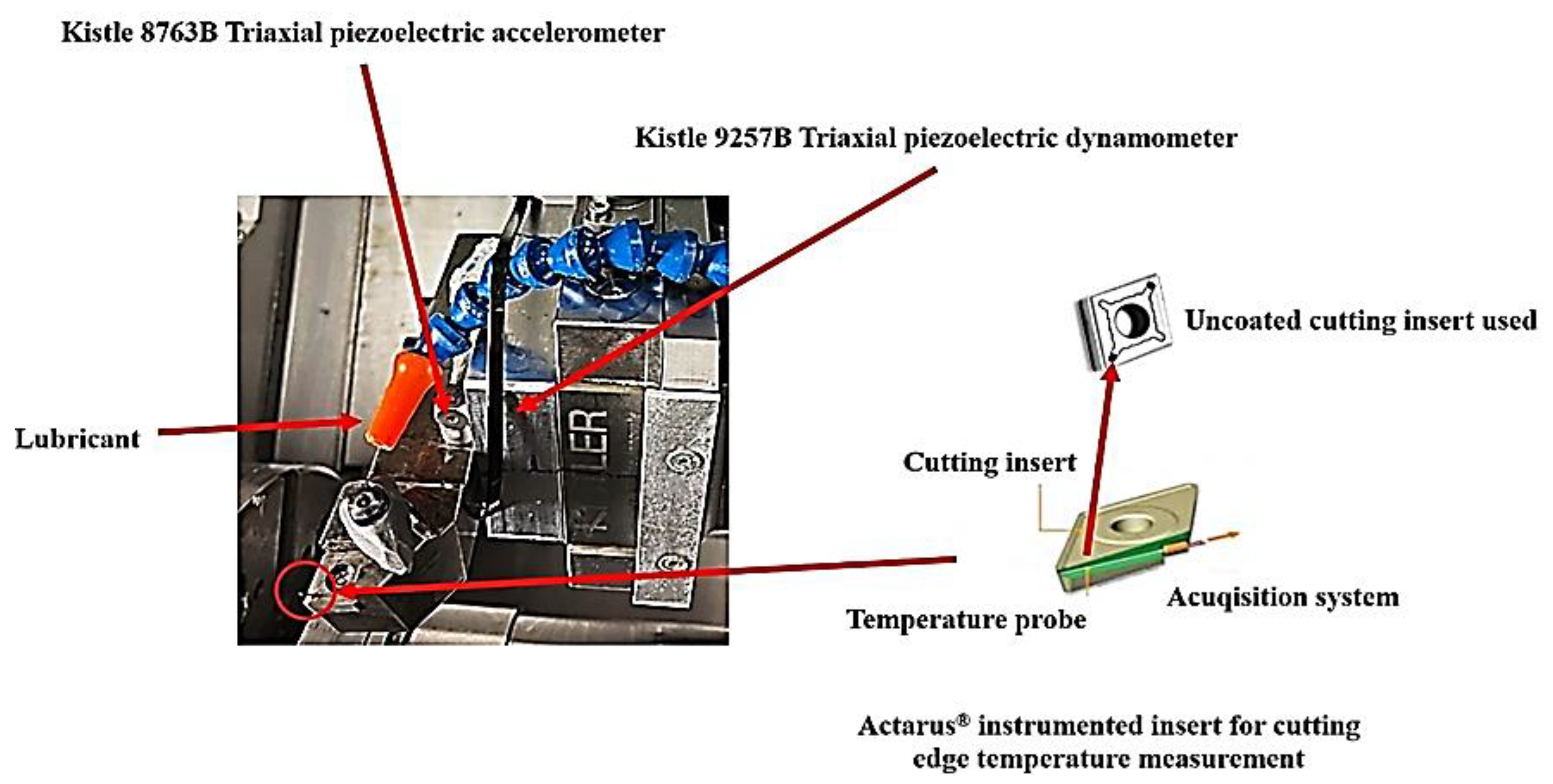
3.5. Metal Cutting Test

Tool-life tests consist of executing cutting experiments with the same cutting edge until the end of life. Using the determined cutting parameters in Section 2.2, tool-life tests of 24CrMoV5-1 steel using sample A1 and B1 coated cutting inserts, commercial uncoated and coated cutting inserts were carried out according to the ISO standard 3685:1993. It is noticeable that cutting-edge radiuses are comparable before and after the deposition of CVD Al2O3 multilayer coatings (samples A1 and B1). Regarding commercial uncoated inserts, edge breakage occurred after the very first seconds. It is shown clearly that these uncoated inserts are not adaptable to the severe cutting conditions applied.
Tool-life plots are shown in Figure 10. Flank wear, cutting edge temperature, roughness of the machined surface, accelerations and cutting forces were measured every 30 s during the cutting tests, as displayed in Figure 11. In these conditions, sample B1 (the coated tungsten carbide cutting insert) exhibits the longest tool life of approx. 650 s, double that of commercial coated inserts. In this study, tool life was evaluated by flank wear-Vb; when flank wear reaches 300 µm or edge breakage occurs, the tool reaches the end of its life.
As can be seen in Figure 11, while cumulated machining time increased, cutting temperatures did not increase until the end of life. As aforementioned, the generated heat in the shear zone could be transported away with chip flow. In this respect, CVD Al2O3 is considered a good thermal barrier for preventing the plastic deformation of substrates [1,7,8]. Compared with α-Al2O3, κ-Al2O3 shows a much smaller thermal conductivity. This could be a plausible explanation for the lower cutting-edge temperatures measured during cutting tests using sample B1 coated cutting inserts [9]. Concerning the roughness of the machined surface, comparable results of approx. 3 µm were obtained at the end of tool life in all three tests.
Cutting forces in different directions were measured. Cutting forces in all directions for tool-life tests using commercial coated cutting inserts were always higher than those using sample A1 and B1 coated inserts, particularly Ft and Ff, indicating that more important powers were required on the spindle for turning using commercial coated inserts. Accelerations in all directions were measured and root mean square values were considered. Indeed, accelerations correlated to cutting vibrations could significantly influence tool service life and tool deflection, and the vibration of tool tip could seriously deteriorate the quality of the machined surface. In this study, smaller accelerations were measured during the test using sample B1 coated cutting inserts. In contrast, it is speculated that large grain size and the higher hardness and roughness of sample A1 generated important vibrations. This could be responsible for the significant chipping reported in Figure 12a.
As shown in Figure 12 and Figure 13, sample A1 and B1 coated inserts were characterized, but we could not characterize this commercial coating due to an industrial confidential issue. Important chipping on the flank face of sample A1 can be observed, showing that wear penetrated the α-Al2O3 layer, revealing Ti(C,N)-based layers, which is not the case for sample B1 except for a small area near the cutting edge. As sample B1 exhibits a good adhesion at the Al2O3/Ti(C,N)-based layer’s interface, this could be a plausible explanation for its good performance in these cutting tests.
Figure 12b,c shows SEM images of sample A1 corresponding to the red and blue squares indicated in Figure 12a. EDS analyses were conducted. The adhesion of the workpiece material to the tool surface and visible cracks were observed. However, the diffusion of cobalt from the substrate is not evident, but it could be possible in the zone where the adhesion of the workpiece material occurs. A similar phenomenon is found in sample B1, as shown in Figure 13b,c, but the diffusion of Co from tungsten carbide substrates into coatings needs further cross-sectional EDS analyses. Accordingly, the adhesion of the workpiece material on tools could generate progressive tool wear. It was suggested that diffusion of Fe and Cr from the workpiece material through grain boundaries into coatings accelerated the degradation of coatings [37]. Furthermore, Ti and Al appear in very limited zones, similar to sample B1. It is assumed that the delamination only occurred at the Al2O3/Ti(C,N)-based layer’s interface, but Ti(C,N)-based layers are adherent to cutting inserts.
Regarding sample B1, as shown in Figure 13a,d, the Built-Up-Edge (BUE) is observed, due to the adhesion of the workpiece material. Moreover, since the cutting-edge temperature was low (approx. 300 °C), only thermal cracks were observed, but there was no evidence for secondary cracks resulting from κ- to α-Al2O3 phase transformation.

4. Conclusions

In this work, four CVD Al2O3 multilayer coatings were deposited without (samples A and B) and with thin TiN top layers (samples A1 and B1). The morphology, microstructure, and mechanical and tribological properties of samples A and B were studied, while turning operations of 24CrMoV5-1 with uncoated and coated tools (commercial coating, samples A1 and B1) were carried out. The main results can be summarized as follows:
(1)
By means of nano-indentation, hardness levels of 28.0 ± 0.8 and 25.6 ± 0.4 Gpa and Young’s moduli of 333 ± 6 and 292 ± 6 GPa were measured for CVD α- and κ-Al2O3 coatings, respectively. Due to the anisotropic properties of α-Al2O3, the influence of film texture on its mechanical properties needs further investigations. Vickers hardness levels of 27.3 ± 1.1 and 25.9 ± 1.0 GPa were measured for CVD α- and κ-Al2O3 coatings, comparable with CVD α- and κ-Al2O3 coatings from the company Bernex.
(2)
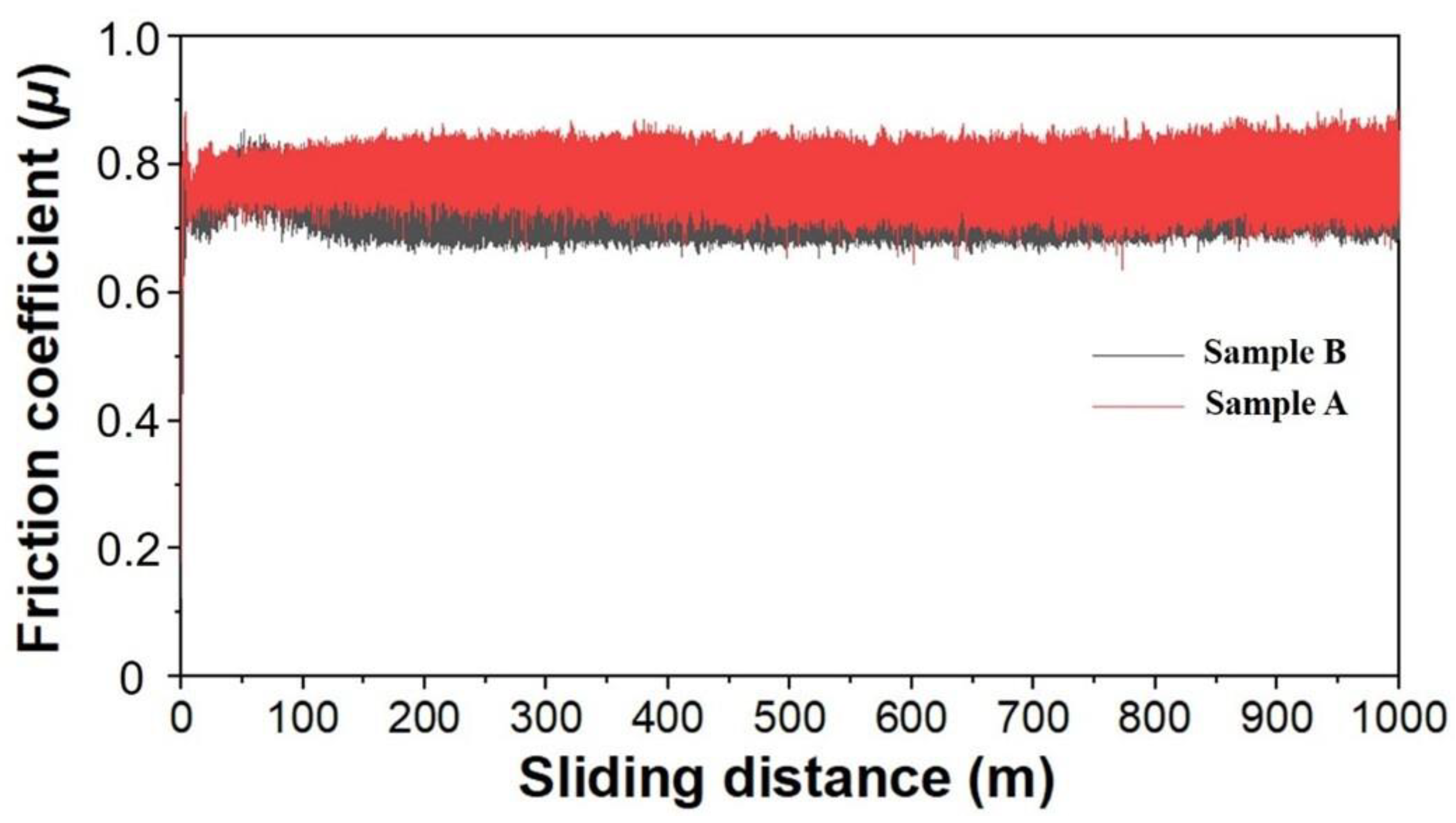
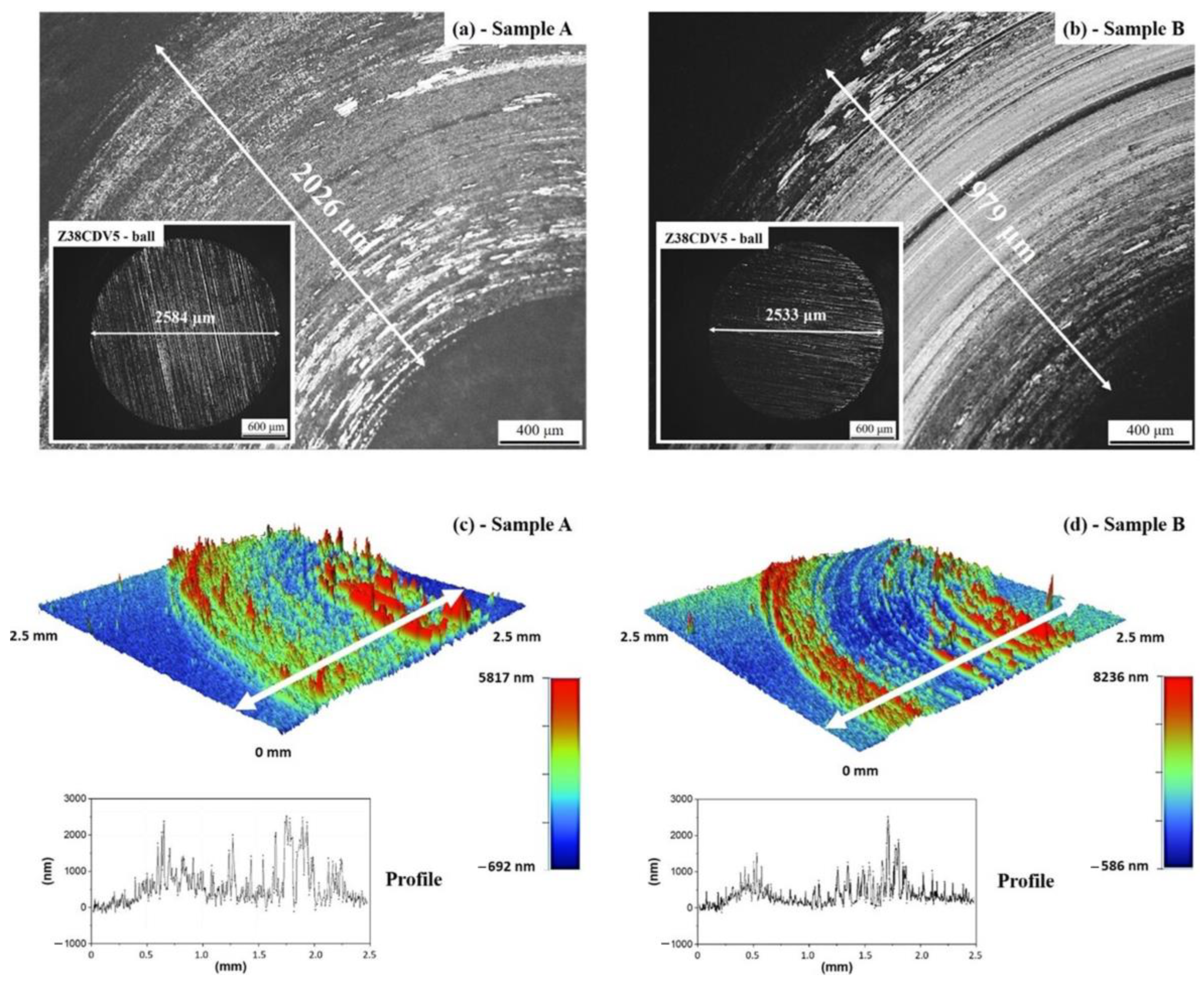
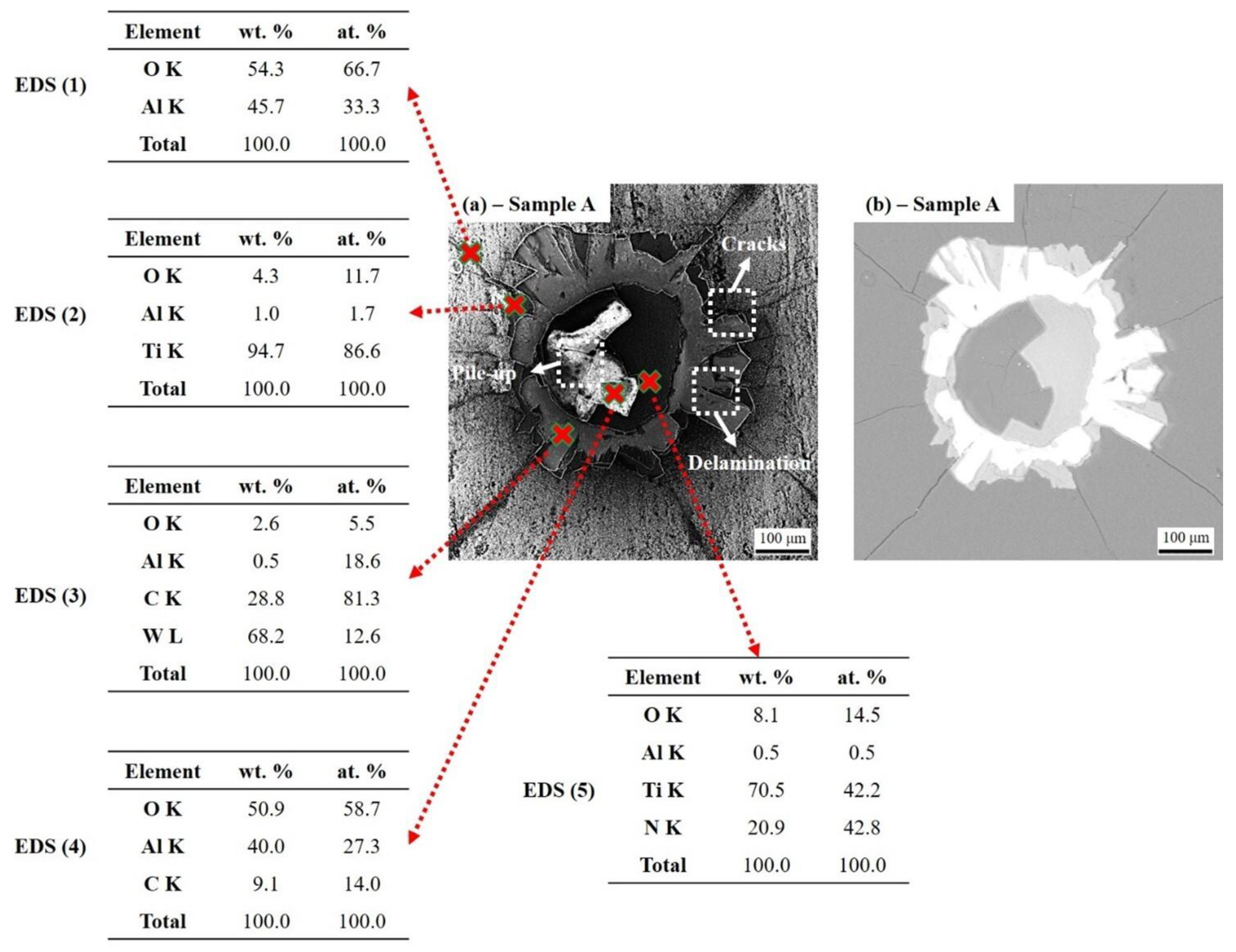
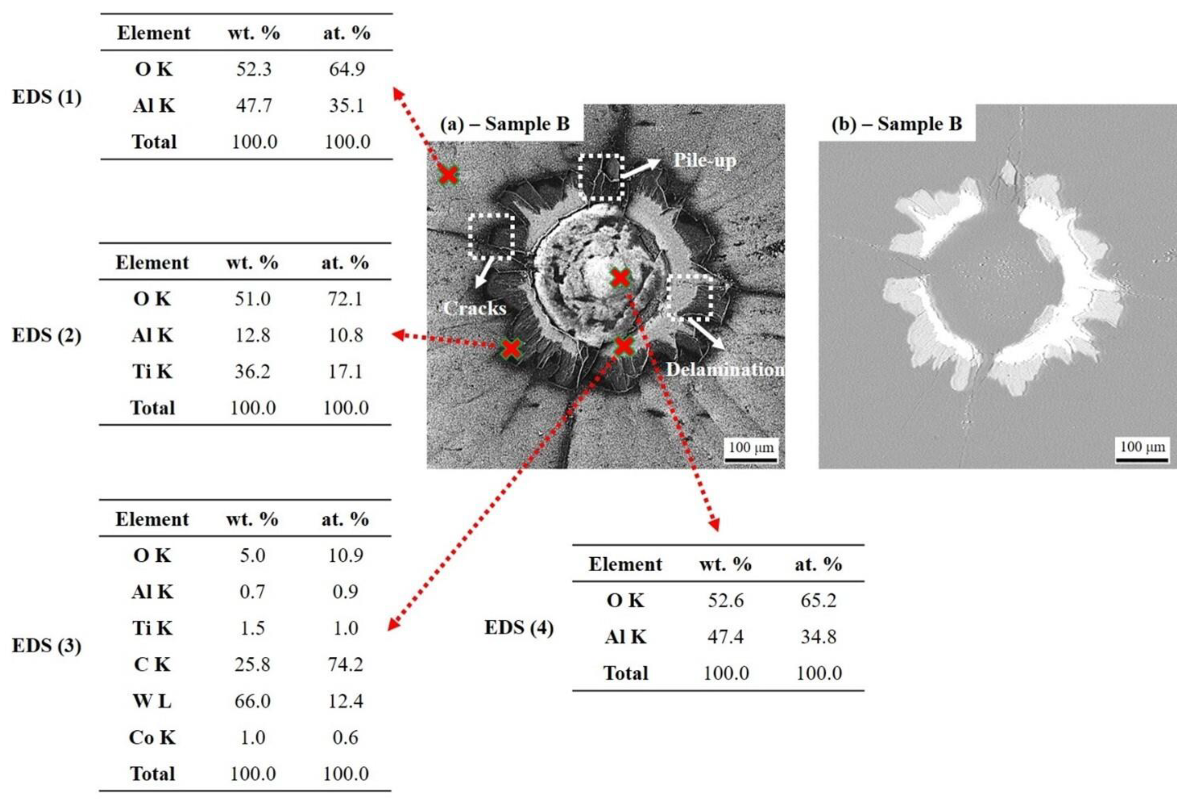
In tribotests using 24CrMoV5-1 balls, friction coefficients of approx. 0.7 were measured for samples A and B, respectively. The effects of grain size, hardness and surface roughness were discussed. In Rockwell C tests, poor delamination but no evident bulking at the center of imprint indicate that sample B could be a good adherent coating.
(3)
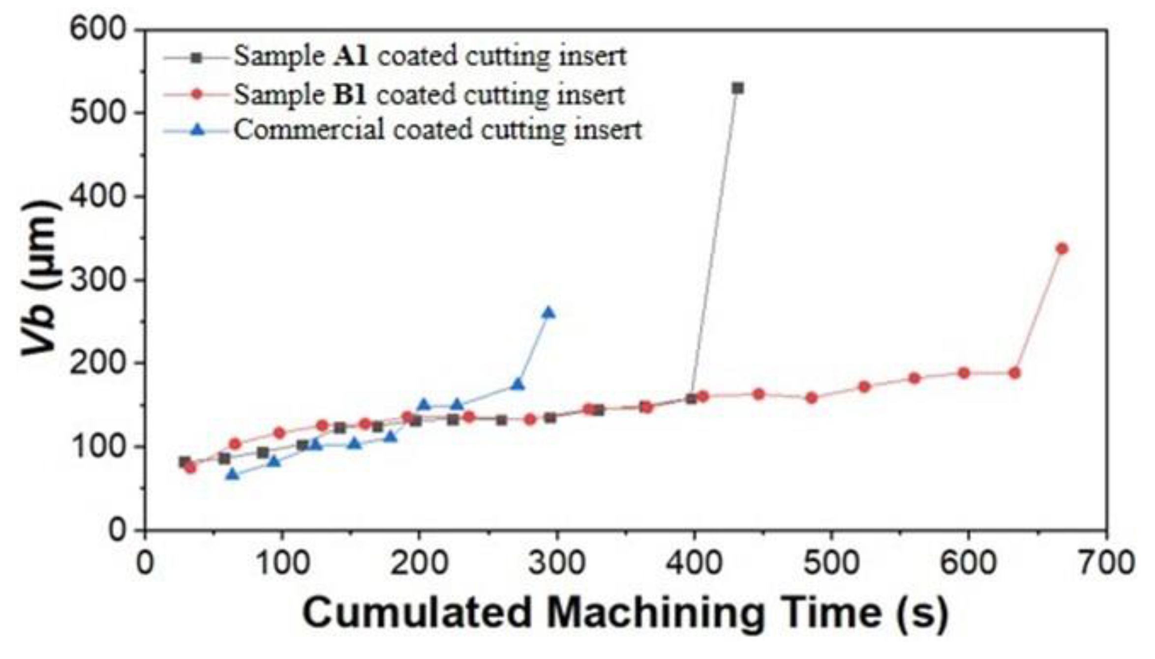
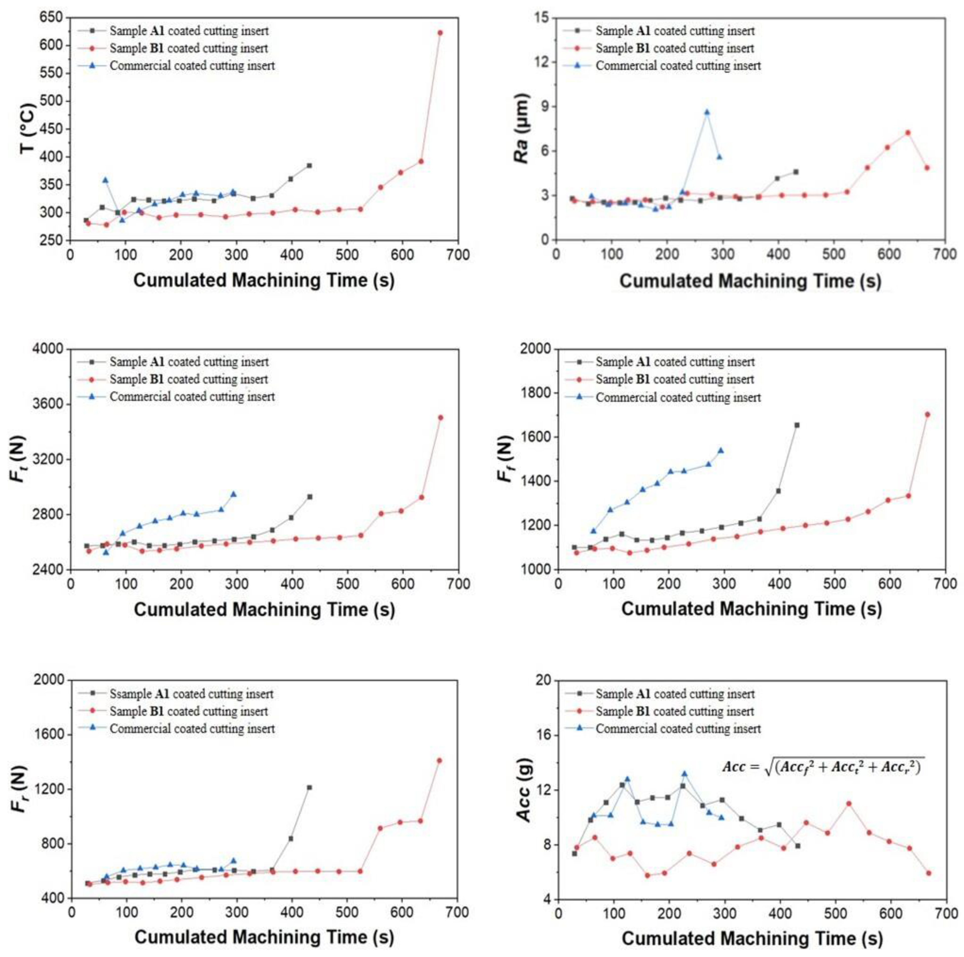
Cutting parameters for tool-life tests of 24CrMoV5-1 were determined according to the COM protocol: cutting speed—240 (m/min), feed—0.35 (mm/rev) and depth of cut—3.5 (mm). In this study, commercial uncoated inserts were not adaptable. Sample B1 coated inserts exhibited the longest tool life of approx. 11 min, double of that of commercial coated inserts from Evatec Tools. Compared to sample A1, good adhesion between κ-Al2O3 and Ti(C,N)-based layers was evidenced in sample B1. The large grain size and high hardness and surface roughness of sample A1 could be responsible for important vibrations that could seriously deteriorate the tool service life.
The results obtained can enrich the existing database for the development of prediction models of tool wear and machined surface quality. They can also help in improving the tool performance for the turning-roughing of 24CrMoV5-1 steel, as the tool life has been dramatically improved compared with the existing commercial CVD Al2O3 multilayer coating. Further works will focus on the optimization of multilayer coating architecture and film texture to improve the adhesion and mechanical properties. The crater wear on the tool rake face also needs more investigations, to study the tool-chip interface.

Author Contributions

Conceptualization, M.Z. and S.A.; methodology, M.Z., S.A., M.P.M., A.D. and A.C.G.-W.; software, M.Z., M.P.M. and C.P.; validation, J.-F.P. and F.S.; formal analysis, M.Z.; investigation, M.Z. and M.P.M.; resources, J.-F.P. and F.S.; writing—original draft preparation, M.Z.; writing—review and editing, M.Z., J.-F.P. and F.S.; supervision, J.-F.P. and F.S. All authors have read and agreed to the published version of the manuscript.

Funding

This research was funded by Groupement d’Intérêt Public Haute-Marne (GIP 52).

Institutional Review Board Statement

Not applicable.

Informed Consent Statement

Not applicable.

Data Availability Statement

No new data were created or analyzed in this study. Data sharing is not applicable to this article.

Acknowledgments

The authors would like to acknowledge the fruitful collaboration with CIRTES SA. The authors thanks Sylvie Migot for the FIB preparation. The “Centre de Compétences” 3M and X-gamma of the Institut Jean Lamour are acknowledged for the access to their equipment. Special thanks to the Groupement d’Intérêt Public Haute-Marne (GIP 52) for its financial support to this work.

Conflicts of Interest

The authors declare no conflict of interest.

References

  1. Schalk, N.; Tkadletz, M.; Mitterer, C. Hard coatings for cutting applications: Physical vs. chemical vapor deposition and future challenges for the coatings community. Surf. Coat. Technol. 2021, 429, 127949. [Google Scholar] [CrossRef]
  2. M’Saoubi, R.; Ruppi, S. Wear and thermal behaviour of CVD α-Al2O3 and MTCVD Ti(C,N) coatings during machining. CIRP Ann. 2009, 58, 57–60. [Google Scholar] [CrossRef]
  3. Nemetz, A.W.; Daves, W.; Klünsner, T.; Ecker, W.; Teppernegg, T.; Czettl, C.; Krajinović, I. FE temperature- and residual stress prediction in milling inserts and correlation with experimentally observed damage mechanisms. J. Mater. Process. Technol. 2018, 256, 98–108. [Google Scholar] [CrossRef]
  4. Nemetz, A.W.; Daves, W.; Klünsner, T.; Ecker, W.; Schäfer, J.; Czettl, C.; Antretter, T. Cyclic heat-up and damage-relevant substrate plastification of single- and bilayer coated milling inserts evaluated numerically. Surf. Coat. Technol. 2019, 360, 39–49. [Google Scholar] [CrossRef]
  5. Krajinović, I.; Daves, W.; Tkadletz, M.; Teppernegg, T.; Klünsner, T.; Schalk, N.; Mitterer, C.; Tritremmel, C.; Ecker, W.; Czettl, C. Finite element study of the influence of hard coatings on hard metal tool loading during milling. Surf. Coat. Technol. 2016, 304, 134–141. [Google Scholar] [CrossRef]
  6. Tzeng, C.J.; Lin, Y.H.; Yang, Y.K.; Jeng, M.C. Optimization of turning operations with multiple performance characteristics using the Taguchi method and Grey relational analysis. J. Mater. Process. Technol. 2009, 209, 2753–2759. [Google Scholar] [CrossRef]
  7. Nemetz, A.W.; Daves, W.; Klünsner, T.; Praetzas, C.; Liu, W.; Teppernegg, T.; Czettl, C.; Haas, F.; Bölling, C.; Schäfer, J. Experimentally validated calculation of the cutting edge temperature during dry milling of Ti6Al4V. J. Mater. Process. Technol. 2020, 278, 116544. [Google Scholar] [CrossRef]
  8. Bobzin, K. High-performance coatings for cutting tools. CIRP J. Manuf. Sci. Technol. 2017, 18, 1–9. [Google Scholar] [CrossRef]
  9. Cahill, D.G.; Lee, S.M.; Selinder, T.I. Thermal conductivity of κ-Al2O3 and α-Al2O3 wear-resistant coatings. J. Appl. Phys. 1998, 83, 5783–5786. [Google Scholar] [CrossRef]
  10. Halvarsson, M.; Vuorinen, S. The influence of the nucleation surface on the growth of CVD α-Al2O3 and κ-Al2O3. Surf. Coat. Technol. 1995, 76–77, 287–296. [Google Scholar] [CrossRef]
  11. Ruppi, S. Influence of Process Conditions on the Growth and Texture of CVD Alpha-Alumina. Coatings 2020, 10, 158. [Google Scholar] [CrossRef]
  12. Zhu, M.; Achache, S.; Emo, M.; Ramírez, A.B.; Pierson, J.F.; Sanchette, F. Influence of the nucleation surface on the growth of epitaxial Al2O3 thermal CVD films deposited on cemented carbides. Mater. Des. 2022, 216, 110601. [Google Scholar] [CrossRef]
  13. Zhu, M.; Achache, S.; Boulet, P.; Virfeu, A.; Pierson, J.F.; Sanchette, F. Effects of deposition parameters on the microstructure and mechanical properties of Ti(C,N) produced by moderate temperature chemical vapor deposition (MT-CVD) on cemented carbides. Vacuum 2022, 195, 110650. [Google Scholar] [CrossRef]
  14. Motta, M.P.; Pelaingre, C.; Delamézière, A.; Ayed, L.B.; Barlier, C. Machine learning models for surface roughness monitoring in machining operations. Procedia CIRP 2022, 108, 710–715. [Google Scholar] [CrossRef]
  15. Uny, F.; Achache, S.; Larmi, S.; Ghanbaja, J.; Fischer, E.; Pons, M.; Blanquet, E.; Schuster, F.; Sanchette, F. Deposition and characterization of (Ti, Al)N coatings deposited by thermal LPCVD in an industrial reactor. Surf. Coat. Technol. 2019, 358, 923–933. [Google Scholar] [CrossRef]
  16. Oliver, W.C.; Pharr, G.M. An improved technique for determining hardness and elastic modulus using load and displacement sensing indentation experiments. J. Mater. Res. 1992, 7, 1564–1583. [Google Scholar] [CrossRef]
  17. Konstantiniuk, F.; Tkadletz, M.; Czettl, C.; Schalk, N. Fracture Properties of α– and κ–Al2O3 Hard Coatings Deposited by Chemical Vapor Deposition. Coatings 2021, 11, 1359. [Google Scholar] [CrossRef]
  18. Qin, Y.F.; Zhu, L.Y.; He, J.N.; Yin, F.X.; Nan, Z.S.; Zhao, L.J. Microstructure and tribological properties of TiCN-Al2O3 composite coatings fabricated by reactive plasma spraying. Vacuum 2018, 147, 149–157. [Google Scholar] [CrossRef]
  19. Vidakis, N.; Antoniadis, A.; Bilalis, N. The VDI 3198 indentation test evaluation of a reliable qualitative control for layered compounds. J. Mater. Process. Technol. 2003, 143–144, 481–485. [Google Scholar] [CrossRef]
  20. Le Coz, G.; Marinescu, M.; Devillez, A.; Dudzinski, D.; Velnom, L. Measuring temperature of rotating cutting tools: Application to MQL drilling and dry milling of aerospace alloys. Appl. Therm. Eng. 2012, 36, 434–441. [Google Scholar] [CrossRef]
  21. Ruppi, S. Deposition, microstructure and properties of texture-controlled CVD α-Al2O3 coatings. Int. J. Refract. Met. Hard Mater. 2005, 23, 306–316. [Google Scholar] [CrossRef]
  22. Ruppi, S. Enhanced performance of α-Al2O3 coatings by control of crystal orientation. Surf. Coat. Technol. 2008, 202, 4257–4269. [Google Scholar] [CrossRef]
  23. Trinh, D.H.; Back, K.; Pozina, G.; Blomqvist, H.; Selinder, T.; Collin, M.; Reineck, I.; Hultman, L.; Högberg, H. Phase transformation in κ- and γ-Al2O3 coatings on cutting tool inserts. Surf. Coat. Technol. 2009, 203, 1682–1688. [Google Scholar] [CrossRef]
  24. De Figueiredo, M.R.; Abad, M.D.; Harris, A.J.; Czettl, C.; Mitterer, C.; Hosemann, P. Nanoindentation of chemical-vapor deposited Al2O3 hard coatings at elevated temperatures. Thin Solid Films 2015, 578, 20–24. [Google Scholar] [CrossRef]
  25. Ruppi, S.; Larsson, A.; Flink, A. Nanoindentation hardness, texture and microstructure of α-Al2O3 and κ-Al2O3 coatings. Thin Solid Films 2008, 516, 5959–5966. [Google Scholar] [CrossRef]
  26. Riedl, A.; Schalk, N.; Czettl, C.; Sartory, B.; Mitterer, C. Tribological properties of Al2O3 hard coatings modified by mechanical blasting and polishing post-treatment. Wear 2012, 289, 9–16. [Google Scholar] [CrossRef]
  27. Konstantiniuk, F.; Tkadletz, M.; Kainz, C.; Czettl, C.; Schalk, N. Mechanical properties of single and polycrystalline α-Al2O3 coatings grown by chemical vapor deposition. Surf. Coat. Technol. 2021, 410, 126959. [Google Scholar] [CrossRef]
  28. Graça, S.; Trabadelo, V.; Neels, A.; Kuebler, J.; Le Nader, V.; Gamez, G.; Döbeli, M.; Wasmer, K. Influence of mosaicity on the fracture behavior of sapphire. Acta Mater. 2014, 67, 67–80. [Google Scholar] [CrossRef]
  29. Norton, A.D.; Falco, S.; Young, N.; Severs, J.; Todd, R.I. Microcantilever investigation of fracture toughness and subcritical crack growth on the scale of the microstructure in Al2O3. J. Eur. Ceram. Soc. 2015, 35, 4521–4533. [Google Scholar] [CrossRef]
  30. Stylianou, R.; Velic, D.; Daves, W.; Ecker, W.; Tkadletz, M.; Schalk, N.; Czettl, C.; Mitterer, C. Thermal crack formation in TiCN/α-Al2O3 bilayer coatings grown by thermal CVD on WC-Co substrates with varied Co content. Surf. Coat. Technol. 2020, 392, 125687. [Google Scholar] [CrossRef]
  31. Davidge, R.W.; Riley, F.L. Grain-size dependence of the wear of alumina. Wear 1995, 186–187, 45–49. [Google Scholar] [CrossRef]
  32. Mukhopadhyay, A.K.; Yiu-Wing, M. Grain size effect on abrasive wear mechanisms in alumina ceramics. Wear 1993, 162–164, 258–268. [Google Scholar] [CrossRef]
  33. Holmberg, K.; Matthews, A.; Ronkainen, H. Coatings tribology-contact mechanisms and surface design. Tribol. Int. 1998, 31, 107–120. [Google Scholar] [CrossRef]
  34. Bull, S.J.; Bhat, D.G.; Staia, M.H. Properties and performance of commercial TiCN coatings. Part 2: Tribological performance. Surf. Coat. Technol. 2003, 163–164, 507–514. [Google Scholar] [CrossRef]
  35. Leyland, A.; Matthews, A. On the significance of the H/E ratio in wear control: A nanocomposite coating approach to optimised tribological behaviour. Wear 2000, 246, 1–11. [Google Scholar] [CrossRef]
  36. Ma, L.; Howard, I.; Pang, M.; Wang, Z.; Su, J. Experimental Investigation of Cutting Vibration during Micro-End-Milling of the Straight Groove. Micromachines 2020, 11, 494. [Google Scholar] [CrossRef] [PubMed]
  37. List, G.; Nouari, M.; Géhin, D.; Gomez, S.; Manaud, J.P.; Le Petitcorps, Y.; Girot, F. Wear behaviour of cemented carbide tools in dry machining of aluminium alloy. Wear 2005, 259, 1177–1189. [Google Scholar] [CrossRef]
Figure 1. Schematic representation of the coating architecture of samples A, B, A1 and B1.
Coatings 13 00883 g001
Figure 2. Cutting forces, accelerations and cutting-edge temperatures measurement systems.
Coatings 13 00883 g002
Figure 3. X-ray diffractograms of samples A and B.
Coatings 13 00883 g003
Figure 4. X-ray diffractograms of samples A1 and B1.
Coatings 13 00883 g004
Figure 5. SEM images showing surface morphologies (top view) and cross-sectional fractures of samples A and B. Note that top layers in these two samples are α- and κ-Al2O3, respectively.
Coatings 13 00883 g005
Figure 6. Friction coefficients measured using 6 mm diameter 24CrMoV5-1 balls at room temperature in air atmosphere without lubricant.
Coatings 13 00883 g006
Figure 7. (a,b) Optical microscope images of wear tracks on the surface of samples A and B. (c,d) 3D profilometer images of wear tracks.
Coatings 13 00883 g007
Figure 8. SEM images and EDS analyses of sample A after Rockwell C test. (a) Secondary electron (SE) image and (b) Backscattered electron (BSE) image.
Coatings 13 00883 g008
Figure 9. SEM images and EDS analyses of sample B after Rockwell C test. (a) Secondary electron (SE) image and (b) Backscattered electron (BSE) image.
Coatings 13 00883 g009
Figure 10. Tool-life plots for cutting tests of 24CrMoV5-1 steel.
Coatings 13 00883 g010
Figure 11. Evolution of cutting-edge temperature-T, average roughness of machined surface-Ra, cutting forces in tangential-Ft, feed-Ff and radial-Fr directions, as well as accelerations-Acc (vibrations in tangential-Acct, feed-Accf and radial-Accr directions) with increasing machining time during tool-life tests.
Coatings 13 00883 g011
Figure 12. SEM images and EDS analyses of the sample A1 (CVD α-Al2O3 coating) coated insert after cutting test of 24CrMoV5-1 steel. (a) Flank face of the cutting insert. (b,c) SEM images corresponding to the red and blue areas indicated in (a). (d) The cutting edge.
Coatings 13 00883 g012
Figure 13. SEM images and EDS analyses of the sample B1 (CVD κ-Al2O3 coating) coated insert after cutting test of 24CrMoV5-1 steel. (a) Flank face of the cutting insert. (b,c) SEM images corresponding to the red and blue areas indicated in (a). (d) The cutting edge.
Coatings 13 00883 g013
Table 1. The deposition parameters of different layers in samples A, B, A1 and B1.
ParametersTiNMT-Ti(C,N)HT-Ti(C,N)α-Bonding Layerκ-Bonding LayerAl2O3
Temperature (°C)9008801005100510051005
Pressure (mbar)707070707070
Deposition time (min)4060151515120
Total flow rate (L.min−1)33.826.132.526.032.525.0
H2 (vol.%)balance
N2 (vol.%)39.620.318.4-9.2-
TiCl4 (vol.%)1.32.41.4-1.2-
CH3CN (vol.%)-0.8----
CH4 (vol.%)--3.4-2.2-
CO2 (vol.%)---3.8-4.0
CO (vol.%)----0.9-
AlCl3 (vol.%)----0.41.6
HCl (vol.%)-----2.0
H2S (vol.%)-----0.3
Table 2. The deposition parameters of different gradient layers.
ParametersGrad 1Grad 2Grad 3Grad 4
Temperature (°C)900 → 890890 → 880880 → 890890 → 1005
Pressure (mbar)70707070
Deposition time (min)10151560
Total flow rate (L.min−1)33.926.126.126.2
H2 (vol.%)balance
N2 (vol.%)39.520.320.316.8
TiCl4 (vol.%)1.62.22.31.6
CH3CN (vol.%)-0.80.8-
CH4 (vol.%)---5.3
Table 3. Experiments carried out for the determination of cutting parameters: cutting speed-Vc (m/min), feed-f (mm/rev) and depth of cut-ap (mm).
SeriesExperience NumberVc (m/min)f (mm/rev)ap (mm)
(A)1 to 31500.32.5
4 to 62400.32.5
7 to 93400.32.5
10 to 125000.32.5
(B)13 to 152400.22.5
16 to 182400.32.5
19 to 212400.452.5
22 to 242400.62.5
(C)25 to 272400.351
28 to 302400.352.5
30 to 322400.353.5
33 to 362400.354.5
37 to 392400.355.5
Disclaimer/Publisher’s Note: The statements, opinions and data contained in all publications are solely those of the individual author(s) and contributor(s) and not of MDPI and/or the editor(s). MDPI and/or the editor(s) disclaim responsibility for any injury to people or property resulting from any ideas, methods, instructions or products referred to in the content.

