Article

Microstructure Evolution and Wear Resistance of the Eutectic High-Entropy Alloy Al0.3CoCrFeNiNb0.5 Produced by Laser Metal Deposition

1
Institute of Materials Science and Engineering, Faculty of Mechanical Engineering, Chemnitz University of Technology, 09107 Chemnitz, Germany
2
Institute of Physics, Faculty of Natural Sciences, Chemnitz University of Technology, 09126 Chemnitz, Germany
3
Center for Materials, Architectures and Integration of Nanomembranes (MAIN), Chemnitz University of Technology, 09107 Chemnitz, Germany
*
Author to whom correspondence should be addressed.
Coatings 2023, 13(3), 585; https://doi.org/10.3390/coatings13030585
Submission received: 10 February 2023 / Revised: 3 March 2023 / Accepted: 6 March 2023 / Published: 8 March 2023
(This article belongs to the Special Issue High-Entropy Alloy Coatings and Surface Functionalization)

Abstract

:
Eutectic high-entropy alloys (EHEAs) are characterized by a fine lamellar microstructure. This allows for homogeneous functional surface properties. Furthermore, the risk of coarse precipitate formation during coating processes from the liquid state is avoided. However, the influence of the size and the texture of the local microstructure domain on functional properties is still unknown. The present work is devoted to the microstructural evolution of the EHEA Al0.3CoCrFeNiNb0.5. Inert gas atomized powder was processed by laser metal deposition (LMD) and spark plasma sintering (SPS). Both specimens were heat treated near their liquidus temperatures. The different production routes have a decisive influence on the orientation of the lamellar structure. The SPS bulk material has a statistically distributed orientation of the lamellae defined by the microstructure of the powder. However, the remelting of the powder during the LMD process causes a directional vertical solidification of the lamellar structure. Based on these differences, positive effects on their functional properties were detected for directionally solidified LMD coatings. As a result of the heat treatment, the influence of the lamellar orientation on their tribological properties is reduced, whereas the influence of the lamellar size on their property profile can be derived.

1. Introduction

High-entropy alloys (HEAs) consist of at least five alloying elements with an atomic content between 5% and 35% [1]. Several studies have already demonstrated the potential of these alloys, particularly in the field of surface protection [2]. Furthermore, eutectic high-entropy alloys (EHEAs) represent a promising approach for coating technologies such as laser metal deposition (LMD) [3]. The risk of coarse segregations during liquid state coating processes is avoided by a fine lamellar microstructure. Although this allows for homogeneous surface properties, the size, shape and texture of the microscopically heterogeneous eutectic structure can influence the property profile. LMD allows for crucial cooling conditions to be controlled by processing parameters. However, predictable and consistent coating properties depend not least on the integrity of the microstructure. Therefore, the effects of thermal exposure also need to be considered. A property-determining influence from the heat treatment of EHEAs has already been confirmed in several studies [4,5,6,7,8]. From these studies, an influence from the alloy composition and the primary structure can be derived. So far, microstructure characteristics and their stability have not been investigated for EHEA coating systems.
Vacuum arc melting is a well-established production route for exploring new alloy compositions in the field of HEAs and EHEAs [4,5,6,7]. Lu et al. [8] investigated for the first time the EHEA AlCoCrFeNi2.1. This alloy system is characterized by high room temperature strength and ductility [8]. Subsequently, further EHEAs with refractory metal additives were developed and investigated in the as-cast state [9,10,11,12]. In a previous study, a fine lamellar structure was detected for the EHEA Al0.3CoCrFeNiNb0.5 in its as-cast state. Furthermore, a high hardness and wear resistance was determined [13]. Due to the variation in cooling conditions during solidification between the surface and the center of the casting, different microstructural domains are formed. Casting defects such as elemental segregations, cracks and pores as well as the suppression of equilibrium phases influence the property profile [1]. Furthermore, elongated columnar grain structures are primarily formed [14,15]. In addition to melt metallurgical production routes such as vacuum arc melting, powder metallurgical approaches are also used to produce bulk materials. In comparison with various sintering processes, the spark plasma sintering (SPS) process in particular offers an efficient and cost-effective option for producing fine crystalline bulk materials [16]. A wide variety of HEAs has been produced by SPS processes [4,17,18,19]. Large regular grains were detected in SPS AlXCoCrCuFeNi bulk material while a dendritic structure was observed in the arc-melted samples [20]. The same difference between the two processing routines was found for the HEA AlXFeNiCrCo [21]. Investigations of the SPS EHEA AlCoCrFeNi2.1 showed a dependency of the microstructure on the sintering temperature. The hardness and wear resistance were improved by a pronounced lamellar structure [22]. Compared to SPS, higher cooling rates of 103 and 104 K/s [23] for the LMD process led to a fine lamellar structure [24]. LMD is assigned to the route from the liquid state. The bond between the coating and the substrate is characterized by high adhesion [1,24]. Various HEAs have been successfully prepared by LMD [25,26]. Due to the direct change to the liquid state, EHEAs are particularly well suited for coating preparation by LMD [27]. Therefore, casting defects and segregation can be effectively reduced [28]. Huang et al. [29] detected a fine and regularly distributed lamellar structure in the LMD AlCoCrFeNi2.1. Hence, its properties were improved compared to the casting [29]. If HEAs or EHEAs are exposed to heat treatment, their microstructure domain and mechanical properties can vary [30,31,32]. Moravcik et al. [4] observed a decrease in the hardness of the sintered HEA AlCoCrFeNiTi0.5 due to a heat treatment at 1100 °C and 1250 °C for 2 h. Sriharitha et al. [20] detected no significant decrease in the hardness of the SPS HEAs Al0.45CoCrCuFeNi and AlCoCrCuFeNi after annealing at 600 °C for 10 h. John et al. [32] recorded a phase transformation of the SPS EHEA AlCoCrFeNi2.1. The B2 phase changed to a disordered BCC phase after heat treatment at 1200 °C for 1 h and 5 h.
In the present study, the powder feedstock of the EHEA Al0.3CoCrFeNiNb0.5 was used to produce the bulk materials by SPS and coatings via LMD. Based on the different process conditions during SPS and LMD and heat treatment, the size and the texture of the local microstructure domain were investigated. The influence of the microstructure’s evolution on the tribological properties was determined. Hence, an analysis of the relation between production routes, microstructure and the property profile can expand upon the understanding of EHEAs. Therefore, suitable application areas can be specified and derived.

2. Materials and Methods

In the current work, the EHEA Al0.3CoCrFeNiNb0.5 was processed through the powder metallurgical processing route of SPS. This technology was applied to produce bulk materials, whereas coatings were manufactured by the melt metallurgical LMD process. Inert gas atomized powder (Nanoval GmbH & Co. KG, Berlin, Germany) was used as feedstock. The feedstock was characterized in detail in a previous study [13]. An SPS KCE FCT-HP D 25-SI (FCT Systeme GmbH, Frankenblick, Germany) was utilized to compact the feedstock powder to bulk materials with a height of 10 mm and a diameter of 40 mm. Graphite tools consisting of two graphite punches, one graphite die and two graphite cones were needed for the SPS route. Graphite foils with a thickness of 0.3 mm were inserted between the feedstock and the punches as well as the die. Reactions with the atmosphere were prevented by flushing the recipient with argon and evacuating it twice (<2 mbar). The consolidation was carried out under a pressure of 50 MPa, at a temperature of 1050 °C and a holding time of 10 min. By a water cooling system at the punches, the cooling was carried out at a cooling rate of approx. 150 K/min down to 300 °C. The coatings were applied using an LMD consisting of a TRUMPF BEO D70 Optic with a prototype TRUMPF 7-ray nozzle and a TRUMPF TruDisk 6001 laser source. The substrate was a round blank of EN1.4301 with a thickness of 6 mm and a diameter of 100 mm. The focal point was set 1.5 mm above the substrate surface. The spot width was approx. 2 mm. A plate feeder was used to continuously feed the powder during the deposition process. The feed rate resulted from the path velocity and the trace offset. The processing was controlled by the axial rotation of a conventional industrial robot. The processing parameters are shown in Table 1.
The bulk material and the coating were heat-treated in a vacuum furnace (Torvac 12 Mark IV) at 1100 °C, close to the liquidus temperature. The liquidus temperature was determined by DSC measurements in a previous study [13]. The heat treatment was carried out at a pressure of ≤10−2 Pa for 12 h at 1100 °C. The applied heating rate was 10 K/min. Cross sections of the SPS bulk material and LMD coating were prepared for analysis using the scanning electron microscope (SEM) LEO 1455VP (Zeiss, Jena, Germany) equipped with a backscattered electron detector (BSD). The accelerating voltage was 25 kV. The integrated energy-dispersive X-ray spectroscopy (EDS) system EDS GENESIS (EDAX, Mahwah, NJ, USA) was used to determine the chemical composition. Phase investigation of the SPS bulk material and LMD coating was realized by X-ray diffraction (XRD) analysis using a Rigaku SmartLab 9 kW instrument equipped with a HyPix-3000 detector (Rigaku Corporation, Tokyo, Japan). Using Cu-Kα radiation (0.15406 nm), a diffraction angle (2Θ) range between 30° and 120° was investigated. The coating thickness was determined at 20 distributed points using the optical microscope GX51 (Olympus, Shinjuku, Japan) equipped with an SC50 camera (Olympus, Shinjuku, Japan). The porosity of the bulk material and coatings was evaluated by an image analysis method with the software ImageJ. The microhardness (Vickers hardness HV0.5) was detected by the Wilson Tukon 1102 device (Buehler, Uzwil, Switzerland) on the cross sections, using a load of 4.903 N applied for five seconds. The average value was calculated from ten individual Vickers indentations for each state. Wear tests were carried out under different tribological conditions to determine the influence of the production route and the heat treatment. The wear behavior of the bulk materials and the coatings was analyzed under sliding, oscillating and abrasive wear conditions. All measurements were carried out at room temperature. The wear test parameters are shown in Table 2. Ball-on-disk testing via the Tetra Basalt Tester (Tetra, Ilmenau, Germany) was used to determine the sliding wear behavior. The scratch test was realized by the CSM Revetest-RST instrument (CSM Instruments SA, Peseux, Switzerland). For investigating the oscillating wear behavior, the Wazau SVT 40 device (Wazau, Berlin, Germany) was utilized. ASTM G 99, ASTM G 171 and ASTM G 133 standards were used to establish the wear test parameters. Furthermore, constant load scratch tests were carried out with 50, 100, 150 and 200 N by the CSM Revetest-RST instrument. The test length was 5 mm. The wear depth and wear area after the ball-on-disk test were characterized by tactile measurements with the Hommel-Etamic T8000. The wear volume was determined using the 3D profilometer MikroCas (LMI, Teltow, Germany). Using a CSM instrument, the wear depth after the scratch tests was detected. The wear tracks after the reciprocating wear tests were evaluated by the 3D profilometer MikroCas to record the wear depth and wear volume. SEM (BSD) was utilized to evaluate the wear tracks from the ball-on-disk and reciprocating tests.

3. Results and Discussion

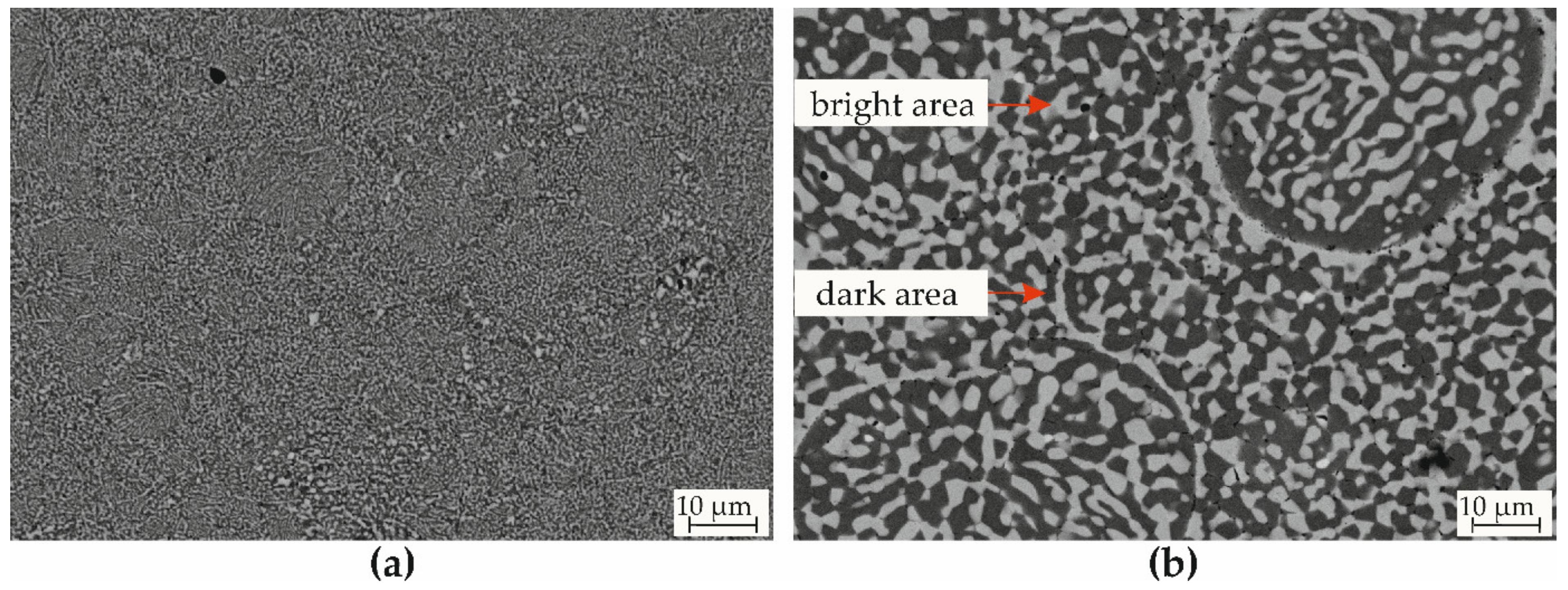
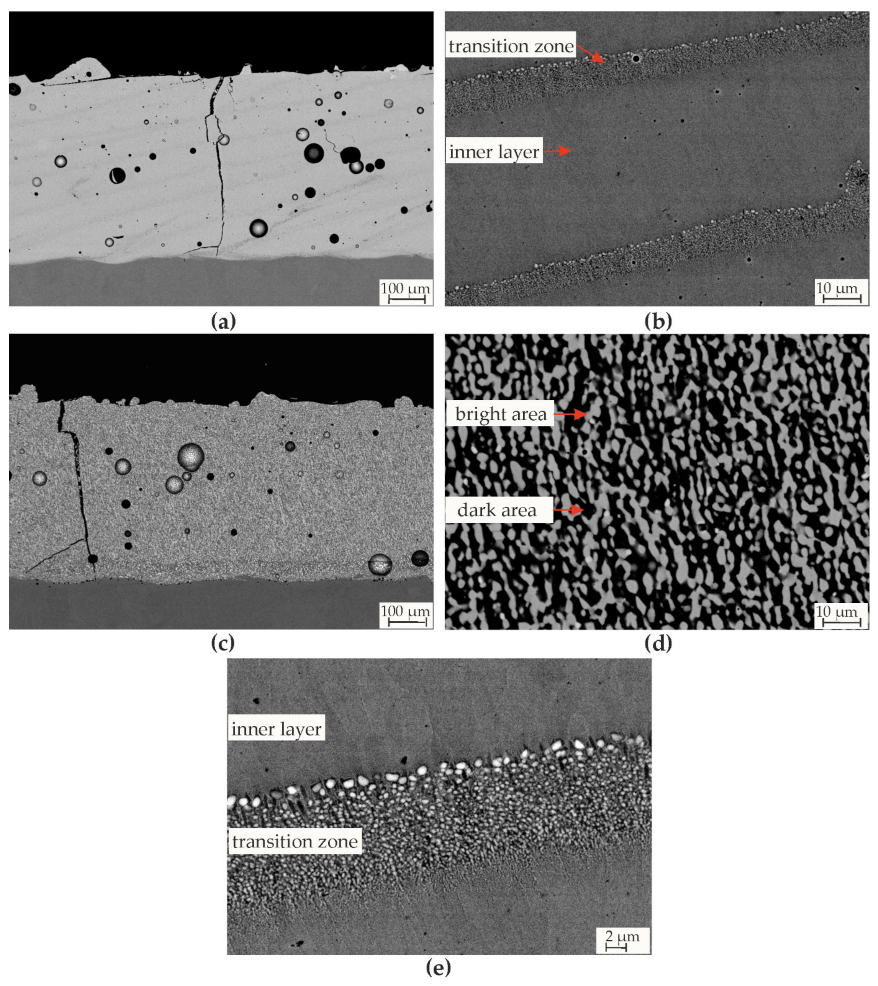
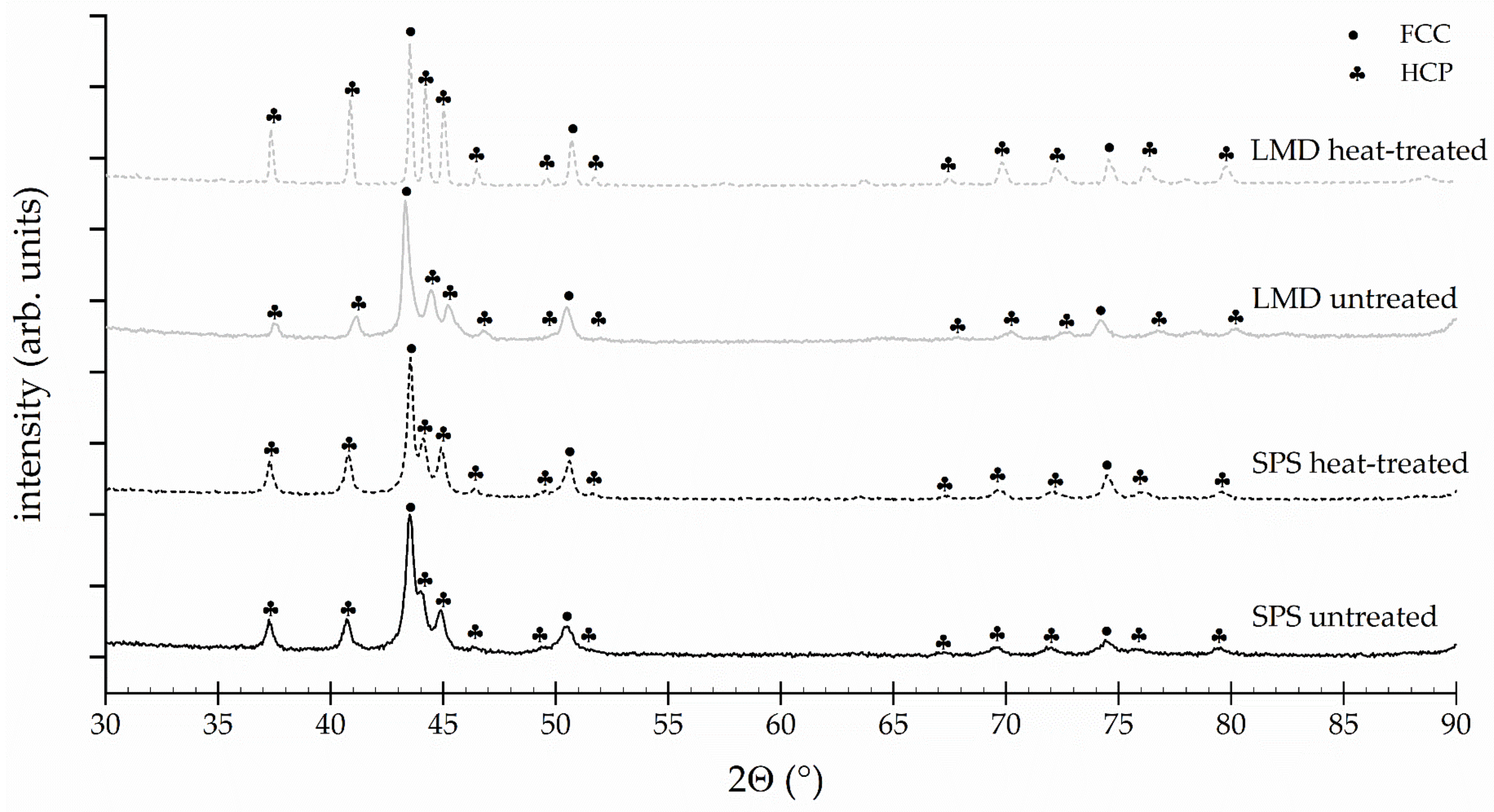
3.1. Microstructure and Phase Formation

The microstructures of the SPS and LMD EHEA Al0.3CoCrFeNiNb0.5 were characterized by SEM with a BSE detector. Images of the untreated and heat-treated SPS bulk material are shown in Figure 1.
The SPS bulk material showed a few pores. A porosity of less than 1% was detected for both states. Both the untreated and heat-treated SPS bulk material exhibited a heterogeneous microstructure. The contrast in the BSD images suggests the presence of at least two phases with different compositions (dark and bright contrast). The dependence of the gray values on the atomic number suggests that the bright-appearing phase is rich in higher atomic number elements such as Nb. The opposite applies to the dark phases. A fine lamellar structure in the untreated condition was detected (Figure 1a). Coarser structures developed between the fine lamellae, especially at the particle boundaries. Different lamellar orientations were observed for the individual particles. During SPS processing, the particles are not remelted. Instead, recrystallization processes occur under high temperatures below the melting temperature and high pressures. Therefore, the microstructure of the feedstock powder is preserved in its lamellar orientation. Consequently, a statistically oriented lamellar structure is formed in the SPS bulk material. The heat treating of the SPS bulk material for 12 h at 1100 °C led to a microstructure coarsening (Figure 1b). The particle boundaries were occasionally marked by pronounced diffusion zones. The differences in the lamellar orientation between the powder particles indicate a coarsening of the initial powder structure.
The coatings were produced by LMD. The microstructures of the coatings in their untreated and heat-treated states are demonstrated in Figure 2.
Despite the good casting properties of eutectic alloys, the LMD coating exhibited cracks and pores. The porosity for the LMD coating was approx. 5%, with a coating thickness of approx. 500 µm. A closed porosity was observed, caused by the melting metallurgical production. The cracks could form because of different thermal expansion coefficients between the substrate and coating in combination with the fast cooling rates of LMD. A previous study on the powdered feedstock material illustrated the presence of pores within the particles [13]. These could have contributed to the pores within the coating. The pores could also have been created by breaking out large unmolded particles during preparation. Strips with a pronounced material contrast were detected, oriented at an angle of approx. 45° to the substrate. These represent the interface between the individual layers (transition zone), which were applied with a small offset of 300 µm. Due to the fusion of the layer surface, light-appearing precipitates were formed in the transition zone. The interface is shown in the detailed images (Figure 2b,e). The LMD coating showed next to the transition zone, an ultrafine lamellar structure (Figure 2e), due to the high cooling rates during LMD. The detailed images (Figure 2e) show a longitudinally solidified microstructure. Directional solidification is caused by the high temperature gradient during cooling of the coating material. Similarly to the SPS bulk materials, a microstructure coarsening after heat treating was observed (Figure 2c,d). A clear material contrast can be seen in the overview image. At least two different phases were recognized.
The chemical composition of the cross sections was determined using an EDS detector. Table 3 shows the results of the EDS measurements. Due to the ultrafine lamellar structure in the untreated states, an area scan was performed instead of point measurements. The measured chemical composition was compared with the nominal composition. For the untreated SPS bulk material, no significant deviation from the nominal values was observed regarding the elements Co, Cr, Fe and Ni. Al and Nb showed larger deviations ≥0.7 at.%. For the heat-treated SPS bulk material, the chemical composition of the light and dark areas within the coarsened eutectic structure (Figure 1b) was recorded. The dark area showed a significantly lower Nb content, whereas the Ni, Fe, Cr and Al contents increased. The bright area was rich in Nb and Co and depleted in Al, Cr, Fe and Ni. Different studies on EHEAs with Nb have shown a similar result with respect to Nb- and Co-rich phases with an HCP lattice structure [30,33,34]. To clarify if different chemical compositions exist between the transition zone and the inner layer in the untreated LMD coating were analyzed, the differences between both areas compared to the nominal composition was ≤1 at.%. The bright area within the heat-treated LMD coating had a higher Nb content than those in the heat-treated SPS bulk material. As a result, the Cr, Fe, and Ni contents decreased. The chemical composition of the dark area in the heat-treated conditions was similar.
The phase formation was investigated by XRD measurements. The diffraction patterns of the untreated and heat-treated bulk material and coating are shown in Figure 3. All measurements exhibited an FCC phase and HCP phase. The highest peak intensity was detected for the FCC phase. With regard to the EDS results, the darker phase of the microstructure could represent the detected FCC structure. Therefore, an FCC solid solution consisting primarily of Al, Co, Cr, Fe and Ni, which was depleted of Nb, was formed. Based on previous studies [33,34] and the EDS measurements, an Nb- and Co-rich HCP phase formed in this alloy system. Detailed examinations of the diffractograms showed a decrease in peak width after heat treatment for both systems. The width of the individual peaks is decisively influenced by the residual stress state and the defect density (Scherrer equation [35]). Both the SPS and LMD coatings showed a reduction of the peak width in the heat-treated state. This is due to diffusion and recrystallization processes. This effect was much more pronounced within the LMD coating since the sintering process reduces the disequilibrium state. A peak shift of the FCC phase to smaller angles and of the HCP phase to higher angles was observed for the untreated LMD coating in Figure 3 compared to all other conditions. Therefore, the lattice spacing of the FCC phase increased and of the HCP phase, decreased. This shift could be attributed to the high cooling rates and consequently reduced diffusion processes during LMD. Accordingly, an FCC solid solution that was supersaturated was formed. Heat treating and sintering led to a peak shift of the FCC phase to higher angles and of the HCP phases to smaller angles. Diffusion and recrystallization could be responsible for this. A similar diffusion tendency of Nb was observed in the EHEA CoCrFeNiNbX [30].
Table 4 shows the lattice parameters derived from the XRD measurements. A slight increase in the lattice parameter of 3.61 Å was detected for the untreated LMD coating. Lattice distortion due to the incorporation of elements with a larger atomic radius such as Nb could have been responsible for this. In the HCP phase of the untreated LMD coating, a decrease in the lattice parameter was detected. This could be attributed to a decrease in the proportions of atoms with a large atomic radius such as Nb. The lattice of the HCP phase was widened and the distortion of the FCC lattice was reduced by recrystallization and diffusion processes during sintering and heat treatment.

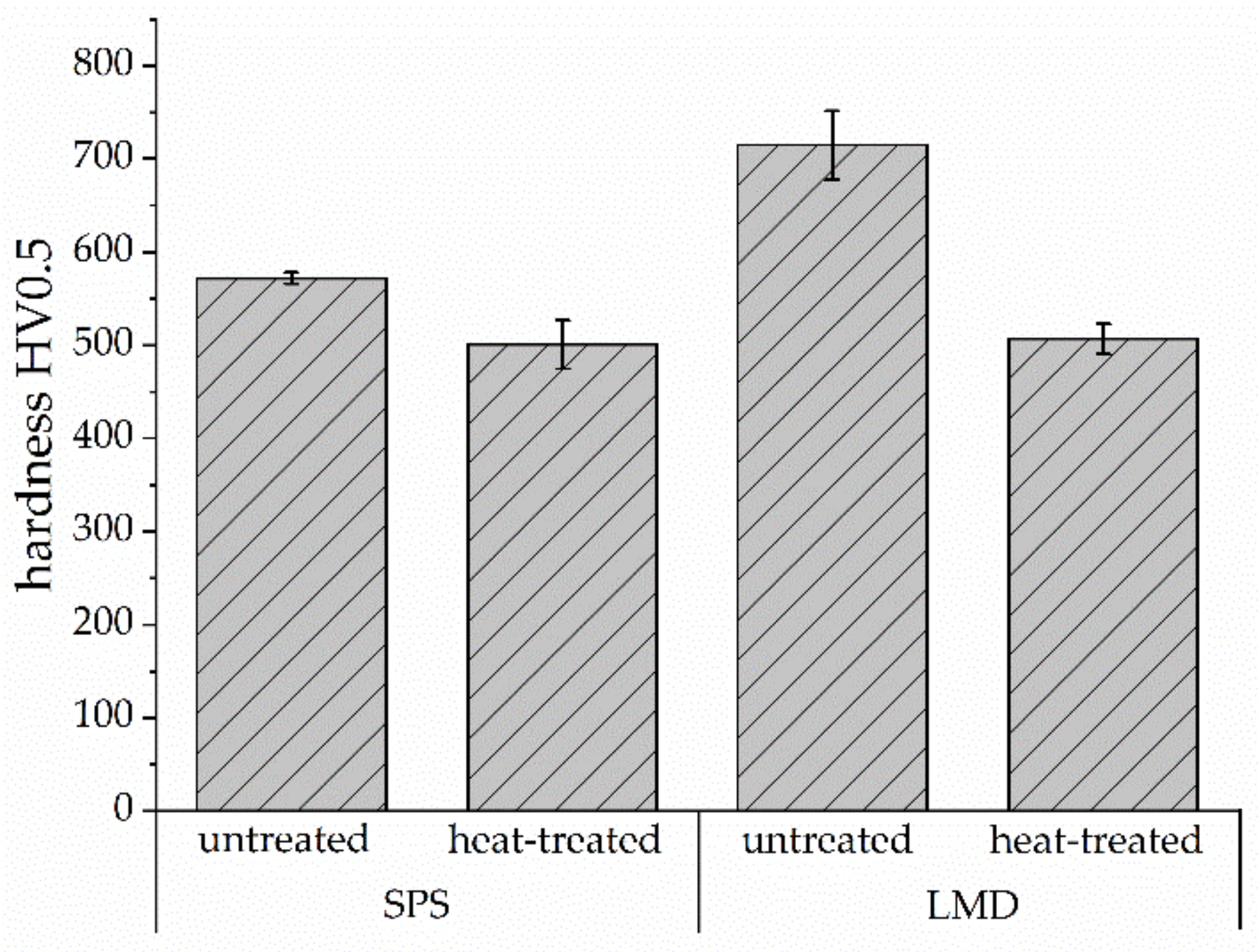
3.2. Microhardness and Wear Behavior

The influence of the production route and heat treatment on the resulting surface hardness was recorded for the EHEA Al0.3CoCrFeNiNb0.5 (Figure 4).
Both production routes showed a heat treatment-induced decrease in hardness. Microstructural coarsening could be the reason. Due to this, the number of phase boundaries decreases, and consequently, dislocation movement is less inhibited. The highest average hardness was achieved for the untreated LMD coating with 715 HV0.5. The high hardness resulted from rapid cooling from the melt. Therefore, an ultrafine lamellar structure could develop in combination with a solid solution strengthening. The untreated SPS bulk material exhibited a significantly lower hardness of 572 HV0.5. The eutectic structure was much more pronounced compared to the untreated LMD coating. This was associated with a decrease in the number of phase boundaries, and consequently, the hardness. In the heat-treated state, no significant difference between the SPS bulk material and the LMD coating in hardness can be seen. Consequently, a similar coarsened eutectic structure was produced regardless of the lamellar size before the heat treatment. The as-cast condition of the EHEA Al0.3CoCrFeNiNb0.5 had a hardness of approx. 650 HV0.5 [13]. This reduced hardness compared to the untreated LMD coating can be attributed to the larger lamellae and lamellar spacing. Löbel et al. also observed a coarsening of the microstructure and an associated decrease in hardness for the HEA AlCrFeCoNi [36].
The correlation between the local microstructure domain size and texture and the wear resistance was investigated. Ball-on-disk, reciprocating and scratch tests were conducted to determine the resistance to different wear conditions. The results of the ball-on-disk test are shown in Figure 5. The untreated LMD exhibited the highest sliding wear resistance, possibly due to the ultrafine lamellar structure and solid solution strengthening. However, the untreated SPS sample was found to have the highest wear depth and wear area compared to all other conditions. The statistical orientation of the microstructure could be the reason for the reduced wear resistance. In contrast, the LMD coating had a structure vertically oriented to the transition zone. The constant rectified phase transitions could reduce the shear of the phase fractions. Independent of the production route, the heat-treated SPS bulk material and LMD coating showed similar wear values. The heat treatment led to an improvement in wear resistance for the SPS bulk material due to homogenization of the microstructure. In particular, the periodic orientation of the microstructure compared to the untreated SPS bulk material improved the wear resistance. The microstructure coarsening led to a decrease in wear resistance compared to the untreated LMD coating. This could be due to the lower hardness and differences in lamellar orientation. Based on a previous study [13] on cast specimens of EHEA Al0.3CoCrFeNiNb0.5, a similar wear depth and volume were determined as for the untreated SPS bulk material. A similar lamellar size and phase composition could account for these.
Detailed investigations of the wear tracks after the ball-on-disk test were carried out to detect the wear mechanism. SEM images (BSD) of the worn surface are shown in Figure 6. The untreated SPS bulk material (Figure 6a) showed a strong material contrast. The darker areas indicate a higher concentration of elements with a low atomic number. EDS measurements of the darker area showed a high amount of oxygen. Hence, oxides were formed. The bright area can be attributed to the EHEA. Flakes and grooves were observed on the oxide layer surface. The two-dimensional oxides were formed by the wear impact. This caused a rapid breakout of oxides, leading to deeper wear tracks. A dislodged particle was also identifiable. The wear track of the untreated LMD coating (Figure 6c) showed primarily grooves and exposed pores. Accordingly, the dominant wear mechanism was abrasion. The heat-treated SPS bulk material (Figure 6b) and LMD coating (Figure 6d) exhibited pronounced flakes on the whole wear surface. Individual grooves and oxidation were still evident, but surface deformation and surface fatigue were dominant. Furthermore, two-dimensional oxides were integrated into the surface.
The oscillating wear resistance of the SPS bulk material and LMD coating was investigated by reciprocating wear tests. The results are shown in Figure 7. The untreated SPS bulk material exhibited the highest wear resistance.
Similar wear depths were recorded as for the Al0.3CoCrFeNiNb0.5 casting [13] investigated in a previous study. On the other hand, the wear volume of the casting was lower. Defects such as pores could be the reason. However, a change in the phase composition of the cast specimen compared to the SPS bulk material due to the melting metallurgical casting production is also possible. Compared to the untreated SPS bulk material, the wear depth and wear volume increased for the untreated LMD coating, possibly due to the brittle behavior of the LMD coating. The untreated and heat-treated LMD coatings as well as the heat-treated SPS bulk material exhibited a similar wear resistance. Hence, the preferred orientation of the phases under oscillating wear conditions had no significant influence.
Figure 8 shows the SEM images (BSD) of the worn surface after reciprocating wear tests. A clear material contrast can be seen for all conditions.
By EDS, increased oxygen content could be qualitatively detected. All conditions exhibited distinct cracks and flakes in the oxidized layer. This indicates the continuous formation and removal of oxides. Plastic deformation along the wear direction was detected for the heat-treated conditions. The SEM images show a pronounced bonding of the oxides in the matrix for the untreated SPS bulk material. It seems to be that the oxides were insufficiently bound to the surface of the untreated LMD coatings and the heat-treated states. The harder and thus more brittle microstructure of the LMD coatings could prevent firm bonding of the oxides. The coarsened microstructures after heat treatment showed significant differences in chemical composition between the phases. Therefore, the formation of stable oxides could be prevented.
Figure 9 summarizes the calculated wear rates after the ball-on-disk and reciprocating wear tests. The comparison of the different wear conditions showed a better resistance to sliding wear than to oscillating wear for the heat-treated SPS bulk material and the LMD coatings. Only the untreated SPS material showed a higher wear rate under sliding wear than under oscillating wear conditions.
Scratch tests were conducted at a progressive load between 1–200 N. The results of are shown in Figure 10. The scratch test curve characteristics allow for a statement about the surface/coating quality. For all conditions, the residual depth increased almost constantly with an increasing load. The straight line gradient of the SPS materials suggests a high surface quality. The highest wear depth for the SPS bulk materials was achieved at a maximum load. The LMD coatings exhibited distinct peaks associated with defects such as pores and cracks. These microstructural defects have already been demonstrated by the SEM images (Figure 2). Consequently, the maximum wear depth was often detected at loads lower than 200 N.
To determine the abrasive wear properties of the EHEA Al0.3CoCrFeNiNb0.5, scratch tests were carried out under the constant loads 50, 100, 150 and 200 N (Figure 11). Therefore, the influence of defects such as pores and cracks was minimized.
The average wear depth significantly increased for the heat-treated conditions at a load of 50 N. The coarsening of the microstructure in connection with the decrease in phase boundaries could be the reason. By increasing the test load to 100 N, the untreated SPS bulk material showed the highest abrasive wear resistance probably due to the low proportion of structural effects in combination with a fine lamellar structure. The untreated LMD coating exhibited the highest average wear depth at 150 N. Brittle behavior and structural defects could be the reason. At the maximum load of 200 N, the influence of heat treatment was almost undetectable for the untreated and heat-treated SPS bulk material. The heat-treated LMD coating exhibited the highest average wear depth at a maximum load. This could be due to the interaction between the coarsened microstructure and the structural defects. An influence of the lamellar orientation on wear resistance under abrasive wear was not observed.

4. Summary and Conclusions

In this study, the influence of the production conditions on the functional properties of EHEA Al0.3CoCrFeNiNb0.5 due to size and texture modifications of the local microstructural domain was investigated. Therefore, the inert gas atomized powder was further processed to bulk materials by SPS as well as to coatings by LMD. A heat treatment at 1100 °C for 12 h was performed. Microhardness measurements and different wear tests were carried out in order to determine the influence of the microstructure characteristics caused by the production route. For the EHEA Al0.3CoCrFeNiNb0.5, the following findings can be drawn:
  • Higher cooling rates in the LMD process compared to SPS led to an ultrafine eutectic structure with solid solution strengthening. Hence, the highest microhardness was detected. Furthermore, directional solidification vertical to the transition zone was determined for the LMD coating. The SPS bulk materials were shown within each particle preferential direction.
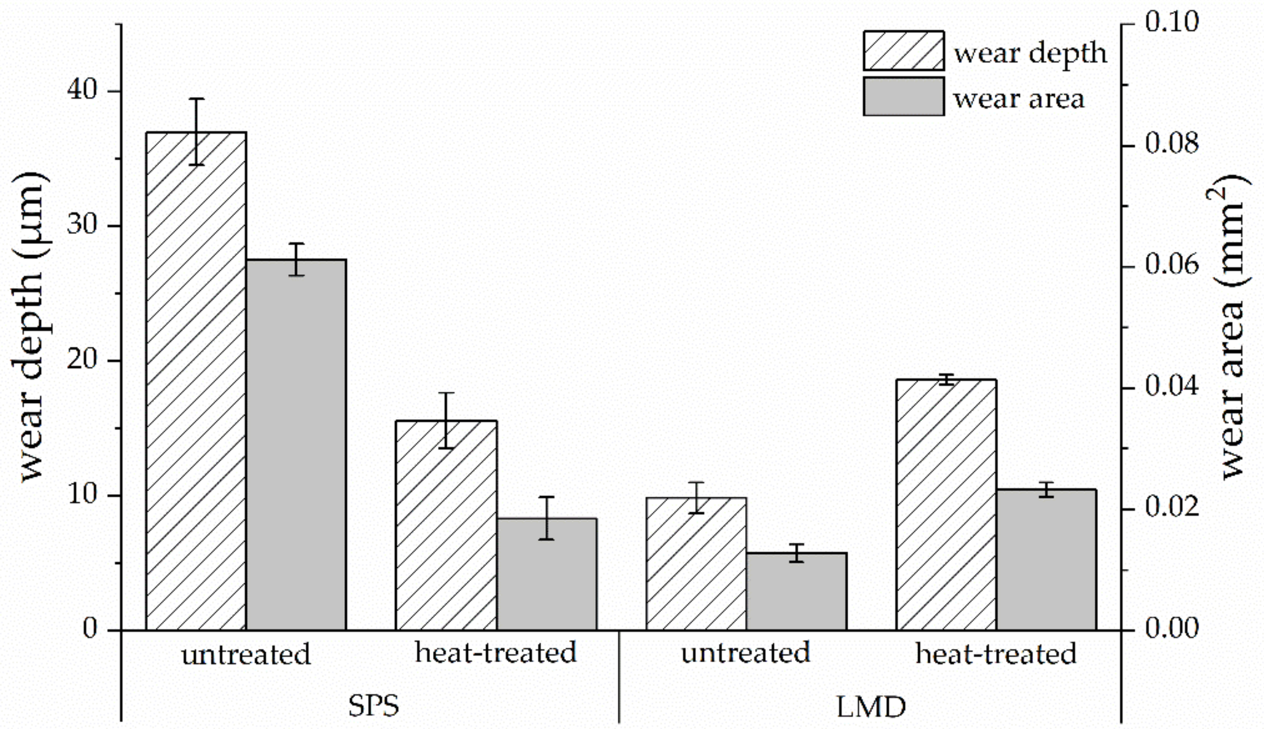
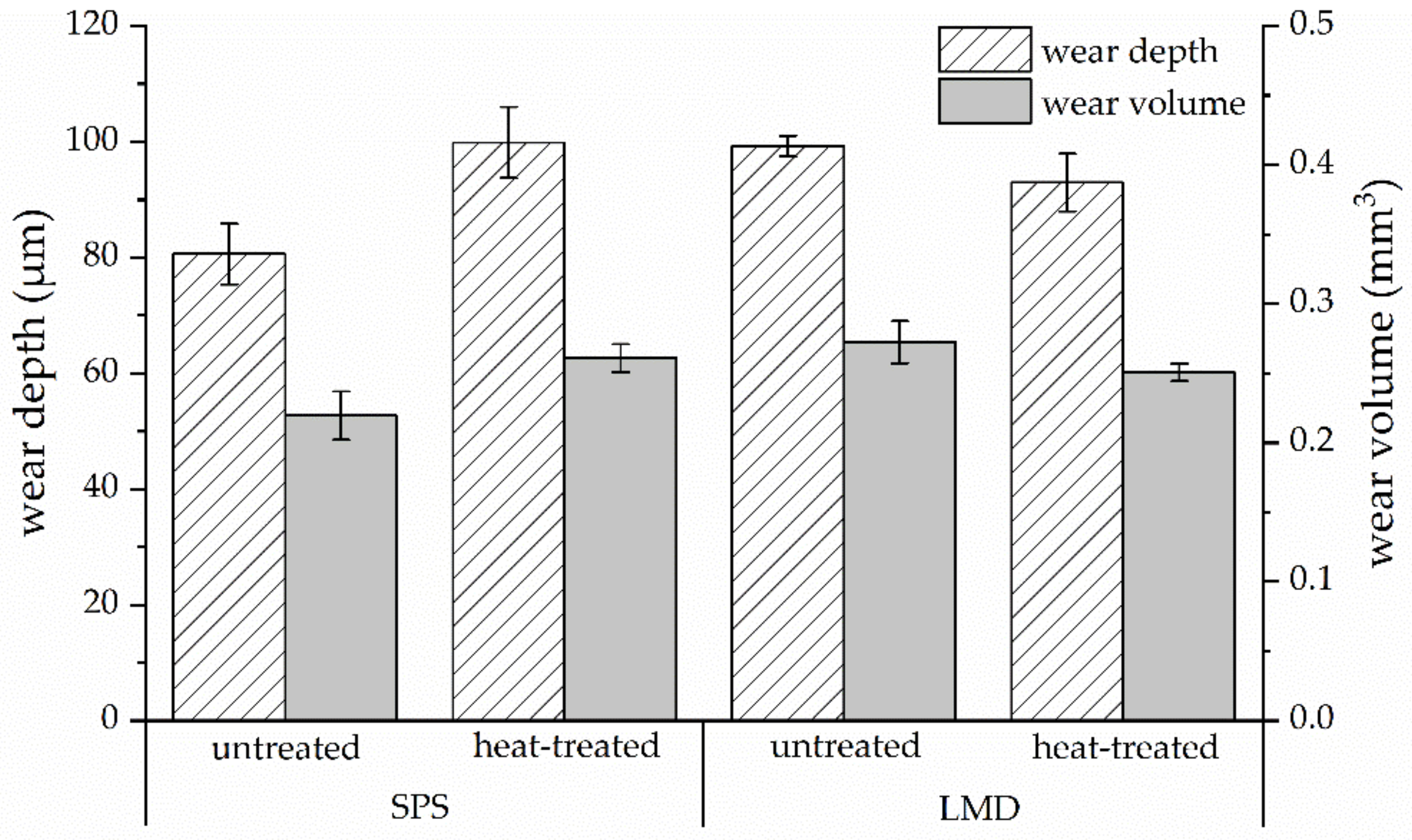
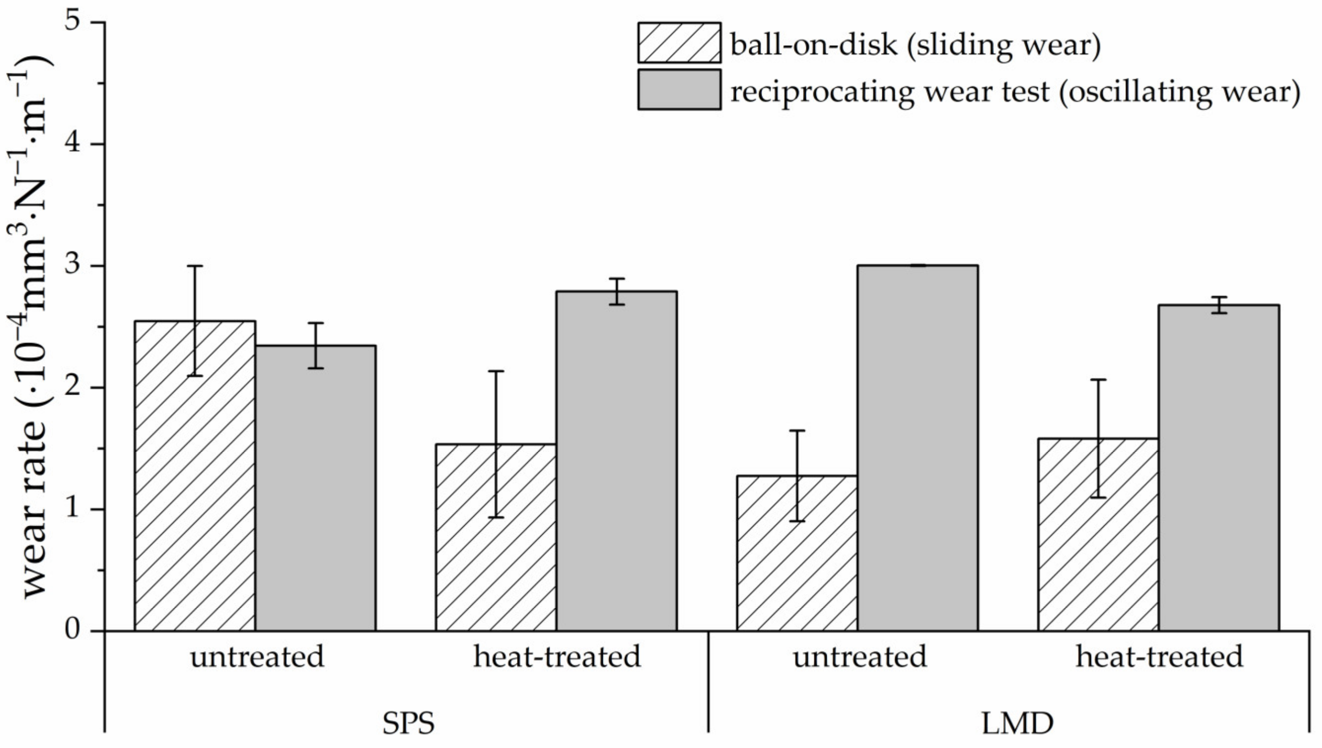
  • The directionally solidified ultrafine lamellar structure of the LMD coating improved the resistance to sliding wear. This could be due to the reduced shear of the directional phase fractions. Meanwhile, the statistically distributed orientation of the lamellar structure in the SPS bulk material caused a higher reciprocating wear resistance. Pronounced bonding of the oxides in the SPS bulk material could be the reason.
  • The lamellar size instead of the preferred orientation dominated the functional properties of the heat-treated LMD coating and SPS bulk material. Hence, the heat-treated specimens with similar lamellar characteristics exhibited a comparable property profile regardless of the production route.
  • An improvement in the sliding wear resistance was realized by heat-treating the SPS bulk material. The periodic orientation of the microstructure compared to the statistically distributed lamellae in the untreated SPS bulk material could be responsible.
The present study demonstrates a microstructural modification of the EHEA Al0.3CoCrFeNiNb0.5 depending on the production route and heat treatment. Therefore, the hardness and wear resistance were decisively influenced. Further tests with different heat treatment parameters have to be conducted to understand the microstructural stability and eutectic reaction. Furthermore, by using other production routes, the influence of the cooling rate and processing conditions on the microstructure and properties should be investigated. Based on these findings, application areas and production routes can be further refined.

Author Contributions

Conceptualization, B.P.; methodology, B.P., T.L. (Thomas Lindner) and T.U.; validation, T.L. (Thomas Lindner), T.U., J.E.T.C. and H.S.; investigation, B.P, T.U., J.E.T.C. and H.S.; writing—original draft preparation, B.P. and T.L. (Thomas Lindner); writing—review and editing, T.L. (Thomas Lindner), G.W., T.S. and T.L. (Thomas Lampke); supervision, T.L. (Thomas Lindner); project administration, T.L. (Thomas Lindner) and T.L. (Thomas Lampke); funding acquisition, T.L. (Thomas Lindner). All authors have read and agreed to the published version of the manuscript.

Funding

This study was funded via Sächsische Aufbaubank–Förderbank/SAB-100382175, by the European Social Fund (ESF) and the Free State of Saxony. The publication of this article was funded by Chemnitz University of Technology and by the Deutsche Forschungsgemeinschaft (DFG, German Research Foundation)—491193532. Coatings 13 00585 i001

Institutional Review Board Statement

Not applicable.

Informed Consent Statement

Not applicable.

Data Availability Statement

Not applicable.

Acknowledgments

The support from Steffen Clauß (Institute of Materials Science and Engineering) is gratefully acknowledged.

Conflicts of Interest

The authors declare no conflict of interest.

References

  1. Gao, M.C.; Yeh, J.-W.; Liaw, P.K.; Zhang, Y. High-Entropy Alloys: Fundamentals and Applications; Softcover Reprint of the Original 1st Edition 2016; Springer International Publishing: Cham, Switzerland, 2018; ISBN 978-3-319-80057-8. [Google Scholar]
  2. Meghwal, A.; Anupam, A.; Murty, B.S.; Berndt, C.C.; Kottada, R.S.; Ang, A.S.M. Thermal Spray High-Entropy Alloy Coatings: A Review. J. Therm. Spray Technol. 2020, 29, 857–893. [Google Scholar] [CrossRef]
  3. Lu, Y.; Dong, Y.; Jiang, H.; Wang, Z.; Cao, Z.; Guo, S.; Wang, T.; Li, T.; Liaw, P.K. Promising Properties and Future Trend of Eutectic High Entropy Alloys. Scr. Mater. 2020, 187, 202–209. [Google Scholar] [CrossRef]
  4. Moravcik, I.; Cizek, J.; Gavendova, P.; Sheikh, S.; Guo, S.; Dlouhy, I. Effect of Heat Treatment on Microstructure and Mechanical Properties of Spark Plasma Sintered AlCoCrFeNiTi0.5 High Entropy Alloy. Mater. Lett. 2016, 174, 53–56. [Google Scholar] [CrossRef]
  5. Singh, S.; Wanderka, N.; Murty, B.S.; Glatzel, U.; Banhart, J. Decomposition in Multi-Component AlCoCrCuFeNi High-Entropy Alloy. Acta Mater. 2011, 59, 182–190. [Google Scholar] [CrossRef]
  6. Yeh, J.-W.; Chen, S.-K.; Lin, S.-J.; Gan, J.-Y.; Chin, T.-S.; Shun, T.-T.; Tsau, C.-H.; Chang, S.-Y. Nanostructured High-Entropy Alloys with Multiple Principal Elements: Novel Alloy Design Concepts and Outcomes. Adv. Eng. Mater. 2004, 6, 299–303. [Google Scholar] [CrossRef]
  7. Zhang, Y.; Zuo, T.T.; Tang, Z.; Gao, M.C.; Dahmen, K.A.; Liaw, P.K.; Lu, Z.P. Microstructures and Properties of High-Entropy Alloys. Prog. Mater. Sci. 2014, 61, 1–93. [Google Scholar] [CrossRef]
  8. Lu, Y.; Dong, Y.; Guo, S.; Jiang, L.; Kang, H.; Wang, T.; Wen, B.; Wang, Z.; Jie, J.; Cao, Z.; et al. A Promising New Class of High-Temperature Alloys: Eutectic High-Entropy Alloys. Sci. Rep. 2015, 4, 6200. [Google Scholar] [CrossRef] [Green Version]
  9. Jiang, H.; Qiao, D.; Lu, Y.; Ren, Z.; Cao, Z.; Wang, T.; Li, T. Direct Solidification of Bulk Ultrafine-Microstructure Eutectic High-Entropy Alloys with Outstanding Thermal Stability. Scr. Mater. 2019, 165, 145–149. [Google Scholar] [CrossRef]
  10. Guo, Y.; Liu, L.; Zhang, Y.; Qi, J.; Wang, B.; Zhao, Z.; Shang, J.; Xiang, J. A Superfine Eutectic Microstructure and the Mechanical Properties of CoCrFeNiMox High-Entropy Alloys. J. Mater. Res. 2018, 33, 3258–3265. [Google Scholar] [CrossRef]
  11. Jiang, H.; Zhang, H.; Huang, T.; Lu, Y.; Wang, T.; Li, T. Microstructures and Mechanical Properties of Co2MoxNi2VWx Eutectic High Entropy Alloys. Mater. Des. 2016, 109, 539–546. [Google Scholar] [CrossRef]
  12. Jiao, W.; Jiang, H.; Qiao, D.; He, J.; Zhao, H.; Lu, Y.; Li, T. Effects of Mo on Microstructure and Mechanical Properties of Fe2Ni2CrMox Eutectic High Entropy Alloys. Mater. Chem. Phys. 2021, 260, 124175. [Google Scholar] [CrossRef]
  13. Preuß, B.; Lindner, T.; Uhlig, T.; Wagner, G.; Lampke, T. Niobium and Molybdenum as Alloying Constituents in Al0.3CoCrFeNi to Develop Eutectic High-Entropy Alloys for HVOF Spraying. J. Therm. Spray Technol. 2022, 1–10. [Google Scholar] [CrossRef]
  14. Wu, Z.; Bei, H.; Otto, F.; Pharr, G.M.; George, E.P. Recovery, Recrystallization, Grain Growth and Phase Stability of a Family of FCC-Structured Multi-Component Equiatomic Solid Solution Alloys. Intermetallics 2014, 46, 131–140. [Google Scholar] [CrossRef]
  15. Wang, W.-R.; Wang, W.-L.; Yeh, J.-W. Phases, Microstructure and Mechanical Properties of AlxCoCrFeNi High-Entropy Alloys at Elevated Temperatures. J. Alloys Compd. 2014, 589, 143–152. [Google Scholar] [CrossRef]
  16. Zhang, A.; Han, J.; Meng, J.; Su, B.; Li, P. Rapid Preparation of AlCoCrFeNi High Entropy Alloy by Spark Plasma Sintering from Elemental Powder Mixture. Mater. Lett. 2016, 181, 82–85. [Google Scholar] [CrossRef]
  17. Ji, W.; Wang, W.; Wang, H.; Zhang, J.; Wang, Y.; Zhang, F.; Fu, Z. Alloying Behavior and Novel Properties of CoCrFeNiMn High-Entropy Alloy Fabricated by Mechanical Alloying and Spark Plasma Sintering. Intermetallics 2015, 56, 24–27. [Google Scholar] [CrossRef]
  18. Moravcik, I.; Cizek, J.; Zapletal, J.; Kovacova, Z.; Vesely, J.; Minarik, P.; Kitzmantel, M.; Neubauer, E.; Dlouhy, I. Microstructure and Mechanical Properties of Ni1,5Co1,5CrFeTi0,5 High Entropy Alloy Fabricated by Mechanical Alloying and Spark Plasma Sintering. Mater. Des. 2017, 119, 141–150. [Google Scholar] [CrossRef]
  19. Riva, S.; Brown, S.G.R.; Lavery, N.P.; Tudball, A.; Yusenko, K.V. Spark Plasma Sintering of High Entropy Alloys. In Spark Plasma Sintering of Materials; Cavaliere, P., Ed.; Springer International Publishing: Cham, Switzerland, 2019; pp. 517–538. ISBN 978-3-030-05326-0. [Google Scholar]
  20. Sriharitha, R.; Murty, B.S.; Kottada, R.S. Alloying, Thermal Stability and Strengthening in Spark Plasma Sintered AlxCoCrCuFeNi High Entropy Alloys. J. Alloys Compd. 2014, 583, 419–426. [Google Scholar] [CrossRef]
  21. Cieslak, J.; Tobola, J.; Berent, K.; Marciszko, M. Phase Composition of AlxFeNiCrCo High Entropy Alloys Prepared by Sintering and Arc-Melting Methods. J. Alloys Compd. 2018, 740, 264–272. [Google Scholar] [CrossRef]
  22. Pan, W.; Fu, P.; Li, Z.; Chen, H.; Tang, Q.; Dai, P.; Liu, C.; Lin, L. Microstructure and Mechanical Properties of AlCoCrFeNi2.1 Eutectic High-Entropy Alloy Synthesized by Spark Plasma Sintering of Gas-Atomized Powder. Intermetallics 2022, 144, 107523. [Google Scholar] [CrossRef]
  23. Shamsaei, N.; Yadollahi, A.; Bian, L.; Thompson, S.M. An Overview of Direct Laser Deposition for Additive Manufacturing; Part II: Mechanical Behavior, Process Parameter Optimization and Control. Addit. Manuf. 2015, 8, 12–35. [Google Scholar] [CrossRef]
  24. Zhang, Y.; Koch, C.C.; Ma, S.G.; Zhang, H.; Pan, Y. Fabrication Routes. In High-Entropy Alloys; Gao, M.C., Yeh, J.-W., Liaw, P.K., Zhang, Y., Eds.; Springer International Publishing: Cham, Switzerland, 2016; pp. 151–179. ISBN 978-3-319-27011-1. [Google Scholar]
  25. Lindner, T.; Liborius, H.; Töberling, G.; Vogt, S.; Preuß, B.; Rymer, L.-M.; Schubert, A.; Lampke, T. High-Speed Laser Metal Deposition of CrFeCoNi and AlCrFeCoNi HEA Coatings with Narrow Intermixing Zone and Their Machining by Turning and Diamond Smoothing. Coatings 2022, 12, 879. [Google Scholar] [CrossRef]
  26. Qiu, X.-W.; Liu, C.-G. Microstructure and Properties of Al2CrFeCoCuTiNi High-Entropy Alloys Prepared by Laser Cladding. J. Alloys Compd. 2013, 553, 216–220. [Google Scholar] [CrossRef]
  27. Wen, X.; Cui, X.; Jin, G.; Liu, Y.; Zhang, Y.; Fang, Y. In-Situ Synthesis of Nano-Lamellar Ni1.5CrCoFe0.5Mo0.1Nbx Eutectic High-Entropy Alloy Coatings by Laser Cladding: Alloy Design and Microstructure Evolution. Surf. Coat. Technol. 2021, 405, 126728. [Google Scholar] [CrossRef]
  28. Baker, I.; Wu, M.; Wang, Z. Eutectic/Eutectoid Multi-Principle Component Alloys: A Review. Mater. Charact. 2019, 147, 545–557. [Google Scholar] [CrossRef]
  29. Huang, L.; Sun, Y.; Chen, N.; Luan, H.; Le, G.; Liu, X.; Ji, Y.; Lu, Y.; Liaw, P.K.; Yang, X.; et al. Simultaneously Enhanced Strength-Ductility of AlCoCrFeNi2.1 Eutectic High-Entropy Alloy via Additive Manufacturing. Mater. Sci. Eng. A 2022, 830, 142327. [Google Scholar] [CrossRef]
  30. Cao, X.; Wu, C.; Liu, Y.; Peng, H.; Su, X. Eutectic Reaction and Microstructure Stability in CoCrFeNiNbx High-Entropy Alloys. Metals 2022, 12, 756. [Google Scholar] [CrossRef]
  31. Jiang, L.; Lu, Y.; Wu, W.; Cao, Z.; Li, T. Microstructure and Mechanical Properties of a CoFeNi2V0.5Nb0.75 Eutectic High Entropy Alloy in As-Cast and Heat-Treated Conditions. J. Mater. Sci. Technol. 2016, 32, 245–250. [Google Scholar] [CrossRef]
  32. John, R.; Karati, A.; Joseph, J.; Fabijanic, D.; Murty, B.S. Microstructure and Mechanical Properties of a High Entropy Alloy with a Eutectic Composition (AlCoCrFeNi2.1) Synthesized by Mechanical Alloying and Spark Plasma Sintering. J. Alloys Compd. 2020, 835, 155424. [Google Scholar] [CrossRef]
  33. Jiang, H.; Jiang, L.; Qiao, D.; Lu, Y.; Wang, T.; Cao, Z.; Li, T. Effect of Niobium on Microstructure and Properties of the CoCrFeNb x Ni High Entropy Alloys. J. Mater. Sci. Technol. 2017, 33, 712–717. [Google Scholar] [CrossRef]
  34. Liu, W.H.; He, J.Y.; Huang, H.L.; Wang, H.; Lu, Z.P.; Liu, C.T. Effects of Nb Additions on the Microstructure and Mechanical Property of CoCrFeNi High-Entropy Alloys. Intermetallics 2015, 60, 1–8. [Google Scholar] [CrossRef]
  35. Scherrer, P. Bestimmung der inneren Struktur und der Größe von Kolloidteilchen mittels Röntgenstrahlen. In Kolloidchemie Ein Lehrbuch; Springer: Berlin/Heidelberg, Germany, 1912; pp. 387–409. ISBN 978-3-662-33517-8. [Google Scholar]
  36. Löbel, M.; Lindner, T.; Clauß, S.; Pippig, R.; Dietrich, D.; Lampke, T. Microstructure and Wear Behavior of the High-Velocity-Oxygen-Fuel Sprayed and Spark Plasma Sintered High-Entropy Alloy AlCrFeCoNi. Adv. Eng. Mater. 2021, 23, 2001253. [Google Scholar] [CrossRef]
Figure 1. Microstructures (SEM, BSD) of the Al0.3CoCrFeNiNb0.5 SPS bulk material: (a) untreated and (b) heat-treated. The contrast in the BSD images suggests the presence of at least two different phases. The untreated SPS bulk material exhibits a fine lamellar structure. Due to the heat treatment, the microstructure coarsened.
Coatings 13 00585 g001
Figure 2. Microstructures (SEM, BSD) of the Al0.3CoCrFeNiNb0.5 LMD coating: untreated (a) overview and (b), (e) detail; and heat-treated (c) overview and (d) detail. A directional solidification was observed in the untreated LMD coating. Due to the heat treatment, the microstructure coarsened and the distortion orientation of the lamellae was less pronounced.
Coatings 13 00585 g002
Figure 3. Diffractograms of Al0.3CoCrFeNiNb0.5 untreated and heat-treated SPS bulk material and LMD coating. An FCC phase and HCP phase were detected for all conditions. A peak shift was observed for the untreated LMD coating. The high cooling rates during LMD could have caused the formation of an FCC supersaturated solid solution.
Coatings 13 00585 g003
Figure 4. Microhardness of the untreated and heat-treated SPS bulk material and laser metal deposited (LMD) sample Al0.3CoCrFeNiNb0.5. The highest hardness was detected for the untreated LMD coating. By heat-treating, a hardness decrease was detected.
Coatings 13 00585 g004
Figure 5. Ball-on-disk test of the untreated and heat-treated SPS bulk material and LMD coating of Al0.3CoCrFeNiNb0.5. The untreated LMD coating showed the highest sliding wear resistance. By heat treating the SPS bulk material, improvement in wear resistance was realized.
Coatings 13 00585 g005
Figure 6. Surfaces (SEM, BSD) of the EHEA Al0.3CoCrFeNiNb0.5 after ball-on-disk testing of (a) untreated and (b) heat-treated SPS bulk material as well as (c) untreated and (d) heat-treated LMD coating. Plastic deformation can be observed for all conditions.
Coatings 13 00585 g006
Figure 7. Reciprocating wear test of the untreated and heat-treated SPS bulk material and LMD coating of Al0.3CoCrFeNiNb0.5. The untreated SPS bulk material exhibited the highest wear resistance. By heat treatment, the wear resistance increased for the LMD coating and decreased for the SPS bulk material.
Coatings 13 00585 g007
Figure 8. Surfaces (SEM, BSD) of the EHEA Al0.3CoCrFeNiNb0.5 after ball-on-disk testing of (a) untreated and (b) heat-treated SPS bulk material as well as (c) untreated and (d) heat-treated LMD coating. Oxidational wear was identified for all conditions. Grooves were detected in the untreated conditions. Due to heat treatment, the wear tracks showed plastic deformation.
Coatings 13 00585 g008
Figure 9. Ball-on-disk (sliding wear conditions) and reciprocating (oscillating wear conditions) wear rates K for the untreated and heat-treated SPS bulk material as well as LMD coating. The untreated SPS bulk material showed a higher resistance to sliding wear. All other conditions showed the contrary.
Coatings 13 00585 g009
Figure 10. Progressive load scratch testing of (a) untreated and (c) heat-treated SPS bulk material as well as (b) untreated and (d) heat-treated LMD coating. The straight line gradient of the SPS bulk materials suggests a high surface quality with a low number of pores and cracks.
Coatings 13 00585 g010
Figure 11. Constant load scratch testing of the untreated and heat-treated SPS bulk material and LMD coating of Al0.3CoCrFeNiNb0.5. Under various constant loads, the untreated SPS bulk material exhibited high abrasive wear resistance.
Coatings 13 00585 g011
Table 1. Laser metal deposition process parameters for Al0.3CoCrFeNiNb0.5.
Power
(W)
Path Velocity
(m∙s−1)
Trace Offset
(mm)
Feeding Rate
(g∙min−1)
Ar Gas Flow Rate
(L∙min−1)
Layer Thickness
(mm)
40000.50.331.012.0approx. 0.5
Table 2. Wear test parameters.
Ball-On-Disk TestReciprocating Wear TestScratch Test
Force20 NForce26 NForceProgressive 1–200 N
Radius5 mmFrequency40 HzSpeed2.5 mm/min
Speed96 RPMTime900 sLength5 mm
Cycles15,916Amplitude0.5 mmTipTruncated diamond cone
Counter bodyAl2O3 (ø 6 mm)Counter bodyAl2O3 (ø 10 mm)Radius200 µm
Table 3. The chemical composition of the untreated and heat-treated EHEA Al0.3CoCrFeNiNb0.5 in at.% detected by EDS.
Production RouteStateAreaAlCoCrFeNiNb
Nominal--6.320.820.820.820.810.5
SPSuntreated-5.620.720.820.920.511.5
heat-treateddark area7.220.222.922.723.83.2
bright area3.520.619.219.117.020.6
LMDuntreatedtransition zone5.820.420.721.020.711.4
inner layer6.420.420.820.520.711.2
heat-treateddark area7.420.322.822.424.13.0
bright area3.420.418.118.616.023.5
Table 4. Lattice parameters of the FCC and HCP phases determined by XRD for the bulk material and LMD coating of the EHEA Al0.3CoCrFeNiNb0.5.
StateLattice Parameter
FCCHCP
SPS untreateda = 3.60 Åa = 4.83 Å   c = 7.85 Å
SPS heat-treateda = 3.60 Åa = 4.82 Å   c = 7.83 Å
LMD untreateda = 3.61 Åa = 4.79 Å   c = 7.77 Å
LMD heat-treateda = 3.60 Åa = 4.85 Å   c = 7.80 Å
Disclaimer/Publisher’s Note: The statements, opinions and data contained in all publications are solely those of the individual author(s) and contributor(s) and not of MDPI and/or the editor(s). MDPI and/or the editor(s) disclaim responsibility for any injury to people or property resulting from any ideas, methods, instructions or products referred to in the content.

