1. Introduction
High-entropy alloys (HEAs) have been the focus of various research approaches for improving surface functionality for a while. Advantages compared to established solutions are expected in terms of high-temperature resistance. The high oxidation resistance of some HEAs makes them interesting as alternative adhesion promoters in thermal barrier coatings [
1,
2]. Furthermore, promising results have already been demonstrated by the wear resistance of different coating systems under elevated operating conditions [
3,
4,
5]. In addition to a promising range of properties, the aspects of sustainability and cost efficiency are other reasons for the increasing interest in complex alloys for surface-protection applications. With regard to the specific coating process, different constitution requirements apply for the feedstock materials of HEAs [
6]. For magnetron sputtering, Schwarz et al. demonstrated good agreement of the coating characteristics for sputtering targets made of a homogeneous alloy and single elements [
7]. In contrast, thermal spraying showed a clear influence on the degree of homogeneity of the element distribution for powder feedstock in the coating properties. Löbel et al. found significant advantages for atomized powders to achieve homogeneous coating properties compared to mechanically alloyed powders or powder blends when processed by atmospheric plasma spraying (APS) [
6,
8]. Comparative studies of different thermal spray processes showed that high-velocity oxy-fuel (HVOF) spraying achieved significantly better conformity to the property profile of casted HEAs compared to the APS process [
6,
9]. In addition, there are increasing efforts to establish laser cladding as an alternative coating approach [
10,
11]. The melting of the substrate surface zone inevitably leads to intermixing with the powder feedstock and to a change in the chemical composition [
12]. By increasing the relative surface speed in high-speed laser metal deposition (HS-LMD) and setting the laser focus point above the substrate surface, the energy input can be effectively limited, and mixing between the substrate and coating material can almost be prevented [
13]. Depending on the intended application, a wide range of processing technologies for HEAs can be used [
14].
Since the alloy systems used in surface technology are largely based on developments in solid materials, the primary objective in coating production is to achieve good transferability of the material properties. In contrast to developments in solid components, which are often focused on mechanical properties, good corrosion and wear protection are of primary importance in the area of surface technology. For this reason, developments in the field of solid materials are limited by suitability for surface-protection applications. Multiphase HEAs are usually used for potential wear-protection applications. However, there are significant differences between the microstructures of castings and those of powder-metallurgically produced coatings, which have a direct effect on the property profile [
15]. Intermetallic brittle phases pose a further problem, favoring crack formation because of thermal stresses during the coating process. Eutectic high-entropy alloys (EHEAs) and the limited formation of intermediate phases by non-metallic alloying constituents represent two promising development approaches for future surface protection materials in complex alloys [
16,
17,
18]. The second approach represents a departure from the usual development approach focused on solid materials. The primary development parameter is often the resistance against wear. In this context, the focus is on established coating materials. For example, the alloying additions of silicon (Si), boron (B), and carbon (C) are typical components of self-fluxing alloys with high wear resistance. As an alloying component in HEAs, these elements have also been used to improve the mechanical properties of various base systems [
19,
20].
Kumar et al. observed improvements in hardness and wear resistance by adding silicon to the CoCrCuFeNi system. Furthermore, a dependence between process route and phase formation was detected. The spark-plasma-sintered samples exhibited an FCC structure and a σ-phase. Accordingly, favoring the formation of σ-phases by the addition of Si was observed. In contrast, the alloys produced by arc melting showed a Ni
3Si phase, only with a higher level of Si content (X = 0.9) [
20]. Regarding hardness, Lizarraga et al. determined the same result in the system CoCrFeNiSi
X [
21].
Previous investigations showed increases in hardness and wear resistance by adding boron [
11,
17]. In the alloy CuCoNiCrAl
0.5FeB
X produced by induction melting, precipitation of borides from Cr and Fe was observed by Hsu et al., whose volume fraction increased by raising the boron content. These factors resulted in hardening of the alloy and good wear resistance [
11,
17].
In addition to the previously mentioned alloying elements, carbon has been shown to contribute to hardness enhancement [
19,
22,
23]. In addition to an FCC phase, M
7C
3 carbides are precipitated, which occupy more volume as the C content increases. These precipitations lead to much hardening of the alloy [
22,
23]. Xiao et al. confirmed a correlation between hardness and scratch resistance [
23]. The effects of SiC on the microstructure and hardness of CoCrFeNi prepared by powder-plasma-arc additive manufacturing showed the formation of Cr
7C
3 phases and an increase in hardness by the addition of SiC [
24]. Khallaf et al. and Kumar et al. confirmed the beneficial effect of finely dispersed precipitates on wear resistance of HEAs [
25,
26].
Various works confirmed the fundamental suitability of these constituents in the context of alloy development in HEAs. Shu et al. used a similar composition of CoCrBFeNiSi for laser cladding. The result was high hardness and wear resistance due to the amorphous phases [
27].
In the present work, wear-resistant HVOF and HS-LMD coatings were developed using HEAs with non-metallic alloying constituents. For this purpose, small amounts of BSiC were added to the equimolar CrFeNi system. The reference was the brazing alloy Ni-600, which is also used as a self-fluxing system in thermal spraying. The maximum operating temperature of such alloys is around 620 °C [
28]. Due to the good high-temperature properties, further improvements are possible through the use of HEAs. Nevertheless, wear resistance at room temperature is a prerequisite. Therefore, the focus of the present study is on the potential wear conditions at room temperature. While the matrix elements of CrFeNi are equimolarly distributed, boron was added to 3.3 wt%, Si to 4.5 wt% and carbon to 0.75 wt% according to the mass-based stoichiometry of Ni-600. This study provides a contribution to an application-oriented development strategy for HEAs in surface technology.
2. Materials and Methods
High-purity materials were mixed in the intended molar ratio according to
Table 1 in order to produce four different alloys. With the exception of boron, which was used as a pre-alloy with nickel, elemental granules, wires or rods with ≥99.9% purity were used as raw materials. First, Fe-Ni was produced in an initial alloying step. Subsequently, silicon was added as granules. Carbon was alloyed from a rod in the next step. Finally, boron was then alloyed over the pre-alloyed NiB system, followed by chromium. Arc melting of the samples was conducted in a water-cooled copper crucible. After evacuating and reaching a pressure of 2 × 10
−4 mbar, the furnace chamber was filled with argon to a pressure of 1.1 bar. A tungsten electrode was used to ignite an arc. All samples were remolded three times and turned after each step to achieve chemical homogeneity. The resulting samples had a diameter of approximately 20 mm and a weight of 10 g. For the arc furnace, a low cooling rate of <50 K/s was determined in preliminary studies [
29,
30].
The solidification behavior was investigated by differential scanning calorimetry (DSC) with a STA 409 C device (Netzsch, Selb, Germany) under argon atmosphere in the temperature range from 1750 K to room temperature with a cooling rate of 20 K/min. Metallographic cross-sections were prepared according to standard metallographic procedures. For the metallographic investigations, an optical microscope GX51 equipped with a SC50 camera (Olympus, Shinjuku, Japan) was used. Hardness measurements (Vickers hardness HV0.5) were conducted with a Wilson Tukon 1102 device (Buehler, Uzwil, Switzerland) in metallographic cross-sections. The average hardness and standard deviation were calculated from ten single indents.
The CrFeNi-BSiC feedstock powder was produced by the company NANOVAL GmbH & Co. KG (Berlin, Germany) using an inert gas atomization process. The feedstock material was investigated by scanning electron microscopy (SEM) using a Zeiss LEO 1455VP (Zeiss, Oberkochen, Germany) microscope. The particle size distribution was examined by laser diffraction analysis in a Cilas 930 device (Cilas, Orléans, France).
Coating deposition was conducted with the liquid fueled HVOF thermal spray system K2 (GTV Verschleißschutz GmbH, Luckenbach, Germany) using the powder feeding system PFW 4/3 S (GTV Verschleißschutz GmbH, Luckenbach, Germany). Prior to the HVOF coating process, the stainless-steel substrates (EN 1.4404) with a diameter of 40 mm and a thickness of 6 mm were prepared by corundum blasting. A pressure of 2.5 bar and the blasting medium Alodur EK F 24 were used. The HVOF coating parameters are summarized in
Table 2. HS-LMD was performed using a TRUMPF BEO D70 Optic (TRUMPF, Ditzingen, Germany) equipped with the prototype of a TRUMPF 7-ray nozzle and a TRUMPF TruDisk 6001 laser source. With a spot width of 2 mm, the focal point was 1.5 mm above the substrate surface. A line offset of 300 µm and a traverse speed of 30 m/min were used. AISI304 grade steel discs with a diameter of 100 mm and a thickness of 6 mm were used as substrate material. The HS-LMD coating parameters for one pass are summarized in
Table 3. The coatings were investigated using an optical microscope GX51 equipped with an SC50 camera. Beraha II etchant was used to contrast the substrate and coating material in cross-sectional view.
For the CrFeNi-BSiC system, the vanishing of elements during coating deposition was recorded. Since energy dispersive X-ray spectroscopy (EDS) is not suitable for the determination of boron and high uncertainties for carbon, the qualitative measurements were performed by glow discharge spectroscopy (GDOES) with a GDA 750 (Spectruma Analytik GmbH, Hof, Germany). A 2.5 mm anode operated at 800 V and 25 mA under 3 hPa Ar pressure was used for the measurements. Measurements were performed for 100 s, and the last 50 s were used for the calculation. The spark plasma sintered state was used as the reference condition. Therefore, both element degradation and contamination can be excluded. A SPS KCE FCT-HP D 25-SI (FCT Systeme GmbH; Frankenblick, Germany) was used to compact the CrFeNi-BSiC starting material with a height of 10 mm and a diameter of 40 mm. Graphite dies were used for the punch and die, and the cones. Graphite foils with a thickness of 0.3 mm provided non-stick properties. Reactions with the atmosphere were prevented by purging the recipient with argon and evacuating it twice (<2 mbar). Solidification was carried out under a pressure of 50 MPa, at a temperature of 1050 °C and a holding time of 10 min. Water cooling at the stamps was used to cool the product down to 300 °C at a cooling rate of approx. 150 K/min.
Phase analyses were conducted by X-ray diffraction (XRD) with a Rigaku SmartLab 9 kW diffractometer with HyPix-3000 detector (Rigaku Corporation, Tokyo, Japan). The XRD experiments were carried out in air using parallel beam geometry with Cu Kα radiation. Assignments of detected signals were performed with the help of the Crystallographic Open Database (COD) plug-in in the Rigaku SmartLab Studio II V 4.1.0.182 software.
To investigate the tribological behavior under sliding, oscillating and scratch wear conditions, ball-on-disk, oscillating wear and scratch tests have been carried out. For the ball-on-disk tests, a Tetra Basalt Tester (Tetra, Ilmenau, Germany) was used. The oscillating wear tests were carried out with a Wazau SVT 40 device (Wazau, Berlin, Germany), and a CSM Revetest-RST device (CSM Instruments SA, Peseux, Switzerland) was used for the scratch tests. The applied parameters are summarized in
Table 4.
The wear depths after the ball-on-disk test were determined using the contact stylus instrument Hommel Etamic T8000 device (Jenoptik, Villingen-Schwenningen, Germany). Resulting wear marks of the oscillating wear and scratch tests were analyzed by laser scanning microscopy (LSM) with a Keyence VK-X200 device (Keyence, Osaka, Japan) to determine the resulting wear depth. The reference material bearing steel EN 1.3505 (100Cr6) was investigated under identical conditions.
3. Results
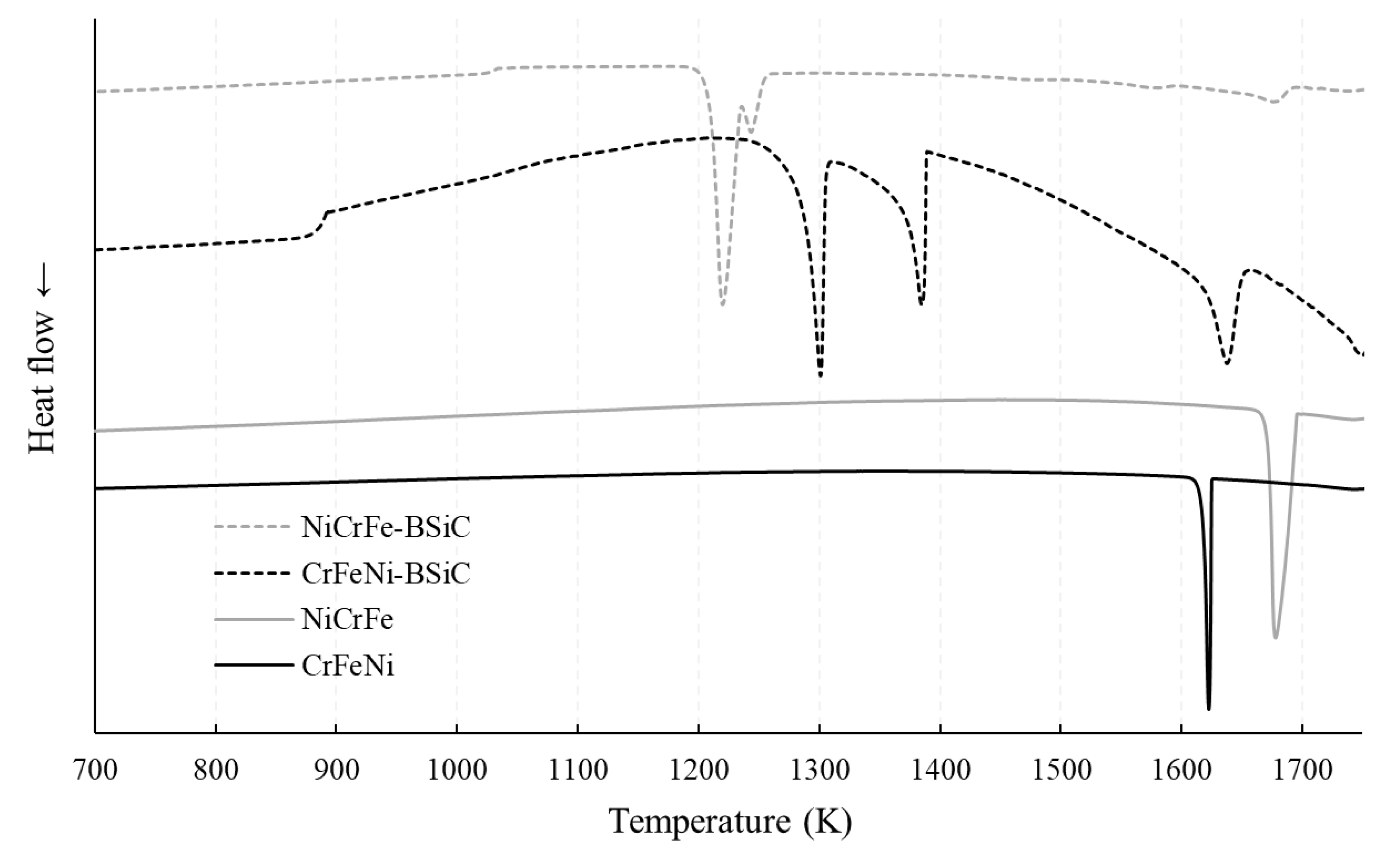
To determine the solidification behavior of the casting, measurements with differential scanning calorimetry (DSC) were carried out. The results are shown in
Figure 1. The liquidus temperatures of the alloys were in the range of 1600 to 1700 K. One exothermic peak was detected in the alloys without BSiC. This indicates that only one phase was formed. The differences between the two alloys were evident in terms of their liquidus and solidus temperature. The alloy NiCrFe with a higher Ni content than CrFeNi liquefied near the melting temperature of pure Ni. In contrast, the liquidus temperature of the solid solution of CrFeNi was lower. In addition, the solidification range in the NiCrFe alloy was wider than that of the CrFeNi alloy. These peaks at higher temperatures also occurred for the alloys containing BSiC with the same amounts of Ni, Cr and Fe.
The peak at approx. 1680 K is only slightly developed in the case of NiCrFe-BSiC. The volume fraction of the FCC phase, which was precipitated, is lower than that of the NiCrFe alloy, so no clear peak was formed during solidification. In contrast, the peak at approx. 1650 K is clearly visible for CrFeNi-BSiC. In addition to the peak at higher temperatures, three other peaks can be seen in the alloys with BSiC. At approximately 900 K for CrFeNi-BSiC and 1020 K for NiCrFe-BSiC, a slight peak was detected. The alloy NiCrFe-BSiC showed two other peaks between 1250 and 1210 K. Similarly, two more peaks were detected between 1300 and 1400 K for the CrFeNi-BSiC alloy, but the distance between the peaks is large (approx. 100 K). Finally, the solidification range of NiCrFe-BSiC from approx. 1020 to 1680 K was less than that of CrFeNi-BSiC, being approx. 900 to 1650 K.
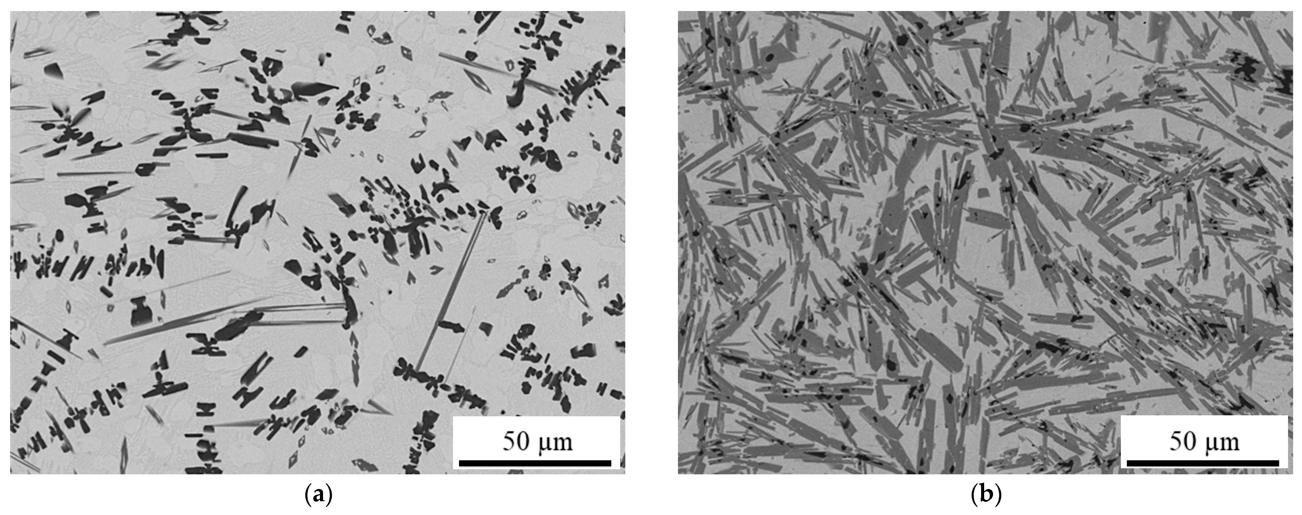
The different melting behavior can also be confirmed by microstructural analysis. For the HEA, a higher proportion of precipitates could be detected in the cross-section than for the nickel-base alloy; see
Figure 2. In addition, based on the cooling curves, it can be assumed that several phases precipitate in the HEA. While the precipitates in the Ni base alloy show a similar contrast, two gray levels are clearly distinguishable in the HEA. The microstructural differences were also accompanied by differences in hardness. For the single-phase starting alloys, average hardness values of 143 ± 9 HV0.5 (NiCrFe) and 157 ± 9 HV0.5 (CrFeNi) were determined. The addition of BSiC significantly increased the average hardness to 927 ± 28 HV0.5 (NiCrFe-BSiC) or 802 ± 57 HV0.5 (CrFeNi-BSiC).
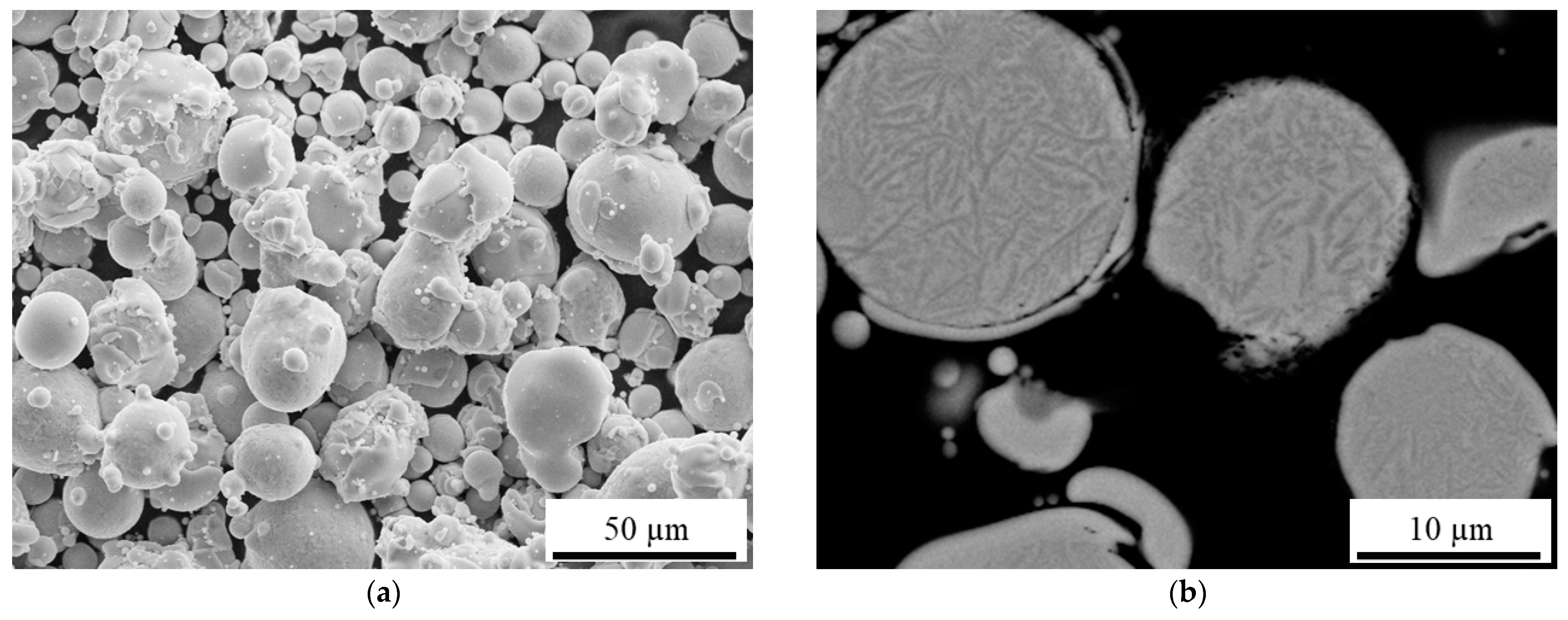
Powder of the alloy CrFeNi-BSiC was successfully produced by inert gas atomization.
Figure 3 shows a largely spherical morphology of the powders. By means of laser diffraction, a fraction width of –65 +14 µm could be determined. A certain number of smaller particles were connected as satellites with larger particles. In the cross-section, precipitates were detected within the particles by using a BSD detector. The morphology of these precipitates was similar to that of the arc-melted samples.
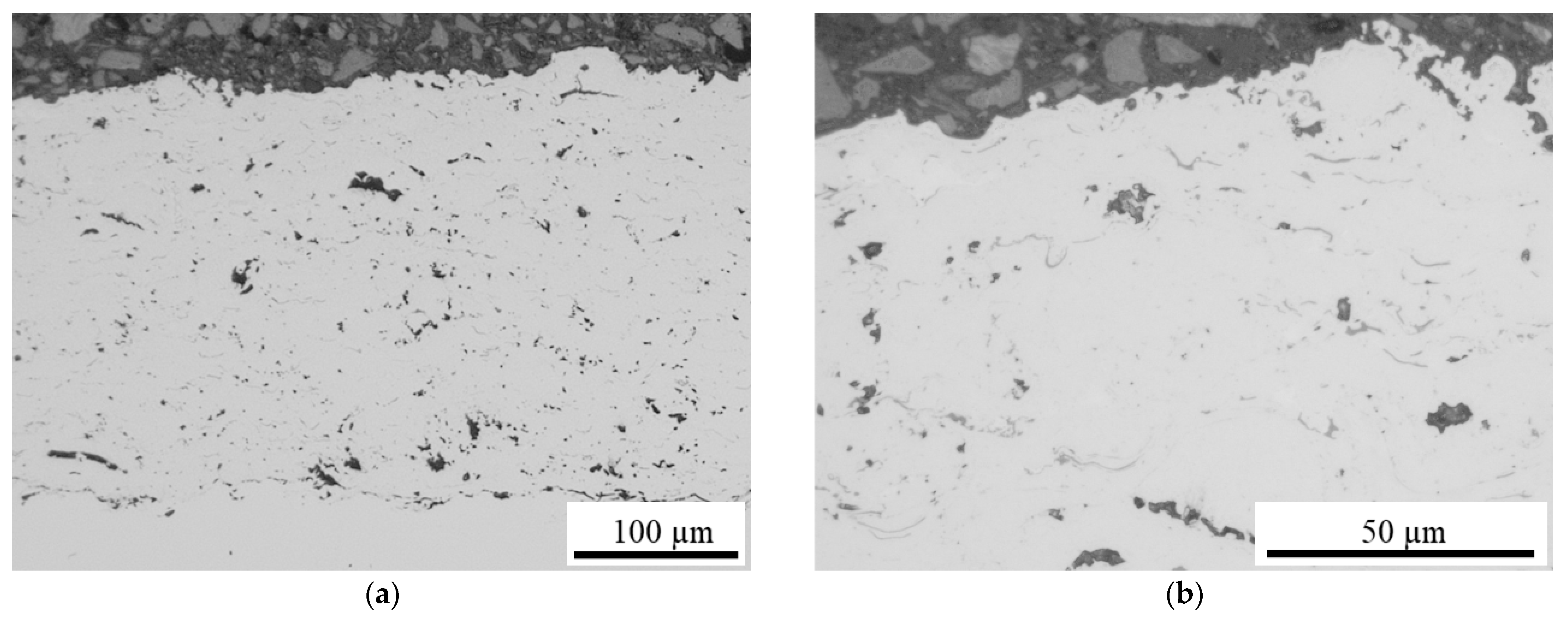
During processing by HVOF and HS-LMD, the powder showed good flow properties. The total coating thickness of about 340 µm was achieved by HVOF spaying. After mechanical surface treatment, the remaining coating thickness was about 280 µm. The transverse micrographs in
Figure 4 confirm good substrate adhesion of the coating system. The HVOF coating showed a porosity of 1.9%, which was homogeneously distributed; pores were present due to the usage of gas-atomized powder [
31]. No contrast due to oxide lamellae or phase segregations could be detected. With HS-LMD, a coating thickness of 750 µm on average could be achieved in one pass.
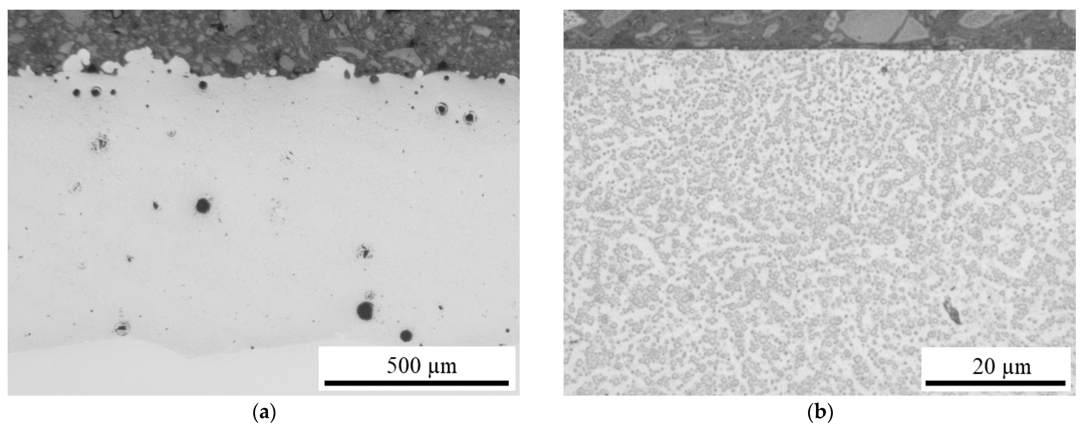
The cross-section images in
Figure 5 show a defect-free bond with the substrate material. Some isolated pores are present in the microstructure, and cracks can be excluded. The detailed image shows finely distributed spherical precipitates, which are clearly different from those of the arc-melted samples. Compared to the arc melted sample, both coatings of the CrFeNi-BSiC alloy showed lower hardness values. However, the hardness value of 730 ± 49 HV0.5 for the HS-LMD coating is slightly higher than that of the HVOF coating (678 ± 59 HV0.5).
The intensity profiles of the SPS, LMD and HVOF specimens were recorded for 100 s using GDOES. In order to exclude surface influences, the 50 s formed the basis for the calculations. First, the background noise was subtracted from the intensities. Then, the determined intensities of the SPS sample were normalized to the nominal values of the feedstock powder material. From this, the determined intensities of the LMD and HVOF coatings were correlated via linear regression. For the LMD coating system, a very good correlation among the individual values was found; see
Table 5. For the intermediate metals and for B, Si and C, high agreement with the nominal values was found. This allows the conclusion that no element burn-off occurred during LMD processing. The intensity of the individual elements was about 95% in relation to the intensities of the SPS sample. The good agreement of the determined ratios despite reduced individual intensities confirms not only the quality of the LMD process but also the characterization approach for evaluating the vanishing of element during processing. For the HVOF coating system, a significant change could be detected, especially for the light elements. The highest percentage change was detectable for carbon with a reduction of about 40%. Boron and silicon showed relative losses of about 20%. In intermediate metals, there was a shift in favor of iron. Chromium, which has high affinity for oxygen, was present in the coating system in lower amounts. It can be said that the atmospheric processing conditions in HVOF have a direct effect on the chemical composition. Elements with oxygen affinity are particularly affected.
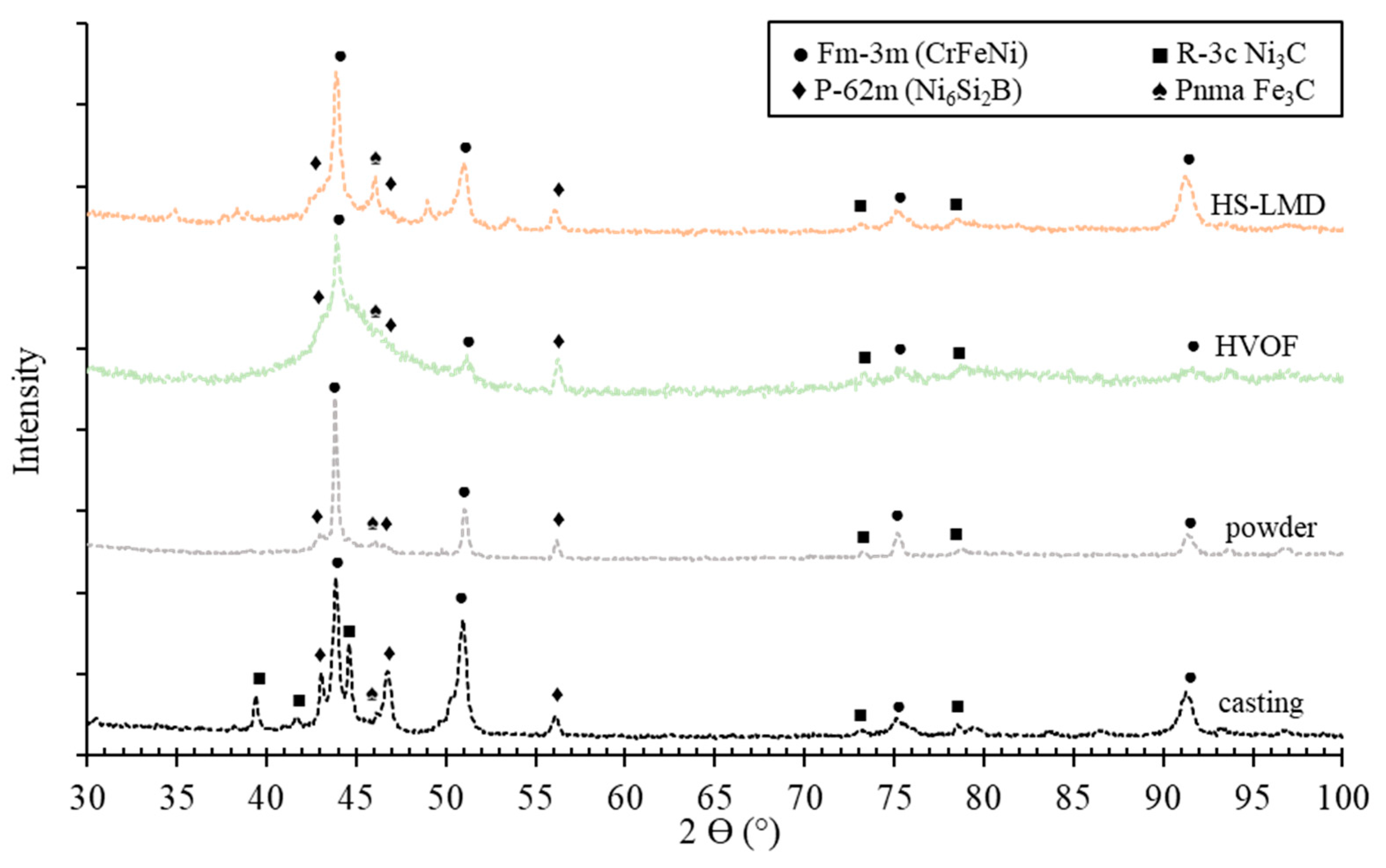
Phase analysis by XRD was performed for the different CrFeNi-BSiC manufacturing states.
Figure 6 shows the resulting diffractograms. The largest diffraction peaks can be assigned to the FCC phase CrFeNi (a = 3.571 Å) of the matrix. In addition, a number of precipitates could be detected, which were most distinct in the casting. This is related to the slow solidification conditions. Only in the casted state could the trigonal Ni
3C phase (a = b = 4.553 Å and c = 12.920 Å) be detected. In contrast, the rapid solidification during powder atomization suppresses segregations to a certain extent. All specimens had the hexagonal Ni
6Si
2B phase with a = b = 6.105 Å and c = 2.895 Å; and the orthorombic Fe
3C phase with a = 5.084 Å, b = 6.738 Å and c = 4.514 Å. In the case of the HVOF coating, there was significant broadening of the main peaks of the FCC phase towards larger angles, partially overlapping other peaks. This may have been due to segregation initiation that was not fully completed by the short thermal cycling. In the case of the HS-LMD coating, there is good agreement with the casting. The powders were completely remelted during processing. Especially for the HS-LMD coating, it is not possible to assign all peaks clearly.
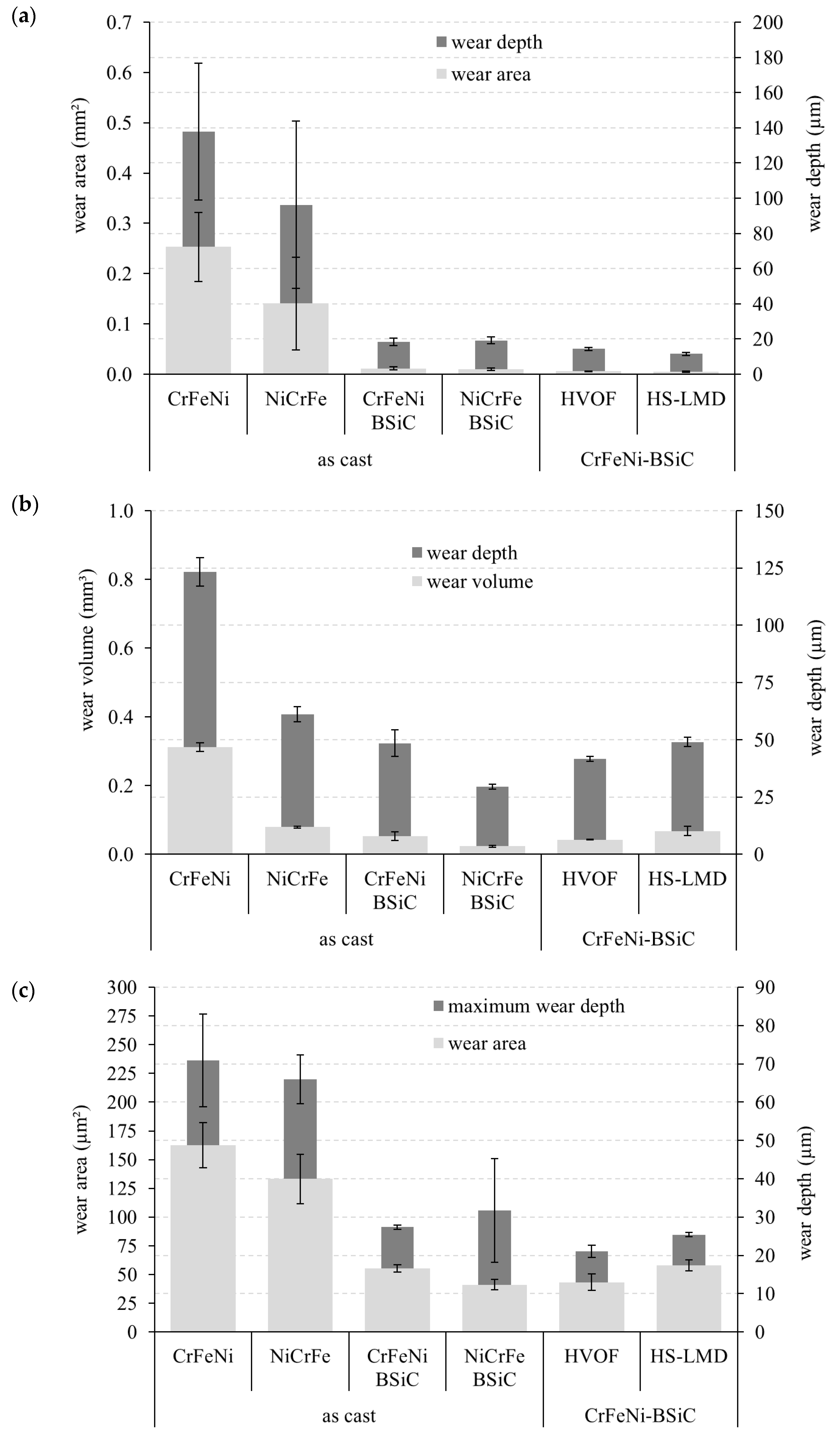
The wear behavior was investigated under sliding, oscillating and scratch conditions. The wear was determined in terms of the maximum wear depth and cross-sectional area of wear for ball-on-disk tracks and along the wear track in the case of the scratch test. The wear volume was determined for the oscillating wear calottes; see
Figure 7. In a comparison of the two three-component systems, a higher resistance of the Ni-based variant can be demonstrated for all wear conditions. This was particularly pronounced under oscillating stress. The addition of BSiC caused a significant increase in wear resistance for both alloys. While almost no difference was observed under sliding stress, certain advantages of NiCrFe-BSiC were detectable under oscillating conditions. In the scratch test, the high standard deviation of the maximum wear depth of the standard variant was noticeable. In comparison to the as-cast and HVOF coating systems for CrFeNi-BSiC, higher resistance of the coating system was demonstrated for all wear conditions. The HS-LMD coating provided the best sliding-wear protection among the systems considered. However, it should be noted that under the constant test conditions, the BSiC-modified systems showed only very low wear-degradation. Under cyclic and scratch loads, the CrFeNi-BSiC alloy showed similar behavior in the as-cast and HS-LMD conditions. It can therefore be assumed that the spherical precipitation form has a positive effect, especially under unidirectional sliding loads. Overall, the results confirm on the one hand the good coating quality, and on the other hand, the fundamental suitability of the development approach for potential protective coating systems.


 ,
, 


