Article

Influence of Milling Conditions on AlxCoCrFeNiMoy Multi-Principal-Element Alloys

1
Department of Component Safety, Bundesanstalt für Materialforschung und -prüfung (BAM), 12205 Berlin, Germany
2
Institute for Materials Science and Joining Technology, Otto-von Guericke Universität Magdeburg, 39105 Magdeburg, Germany
3
Institute of Materials Science and Engineering, Chemnitz University of Technology, 09107 Chemnitz, Germany
*
Author to whom correspondence should be addressed.
Coatings 2023, 13(3), 662; https://doi.org/10.3390/coatings13030662
Submission received: 6 January 2023 / Revised: 15 March 2023 / Accepted: 20 March 2023 / Published: 22 March 2023
(This article belongs to the Special Issue High-Entropy Alloy Coatings and Surface Functionalization)

Abstract

:
Multi-Principal-Element or High-Entropy Alloys (MPEAs/HEAs) have gained increasing interest in the past two decades largely due to their outstanding properties such as superior mechanical strength and corrosion resistance. However, research studies on their processability are still scarce. This work assesses the effect of different machining conditions on the machinability of these novel alloys, with the objective of advancing the introduction of MPEA systems into industrial applications. The present study focuses on the experimental analysis of finish-milling conditions and their effects on the milling process and resulting surface finish of CoCrFeNi, Al0.3CoCrFeNi and Al0.3CoCrFeNiMo0.2 alloys fabricated via Spark Plasma Sintering. Ball-nose-end milling experiments have been carried out various milling parameters such as cutting speed, feed per cutting edge, and ultrasonic assistance. In situ measurements of cutting forces and temperature on the tool edge were performed during the experiments, and surface finish and tool wear were analyzed afterwards. The results exhibited decreasing cutting forces by means of low feed per cutting edge and reduced process temperatures at low cutting speed, with the use of ultrasonic-assisted milling. It was shown that the machinability of these modern alloys through conventional, as well as modern machining methods such as ultrasonic-assisted milling, is viable, and common theories in machining can be transferred to these novel MPEAs.

1. Introduction

Conventional alloys, such as Fe-based steels, are based on one principal element to which other minor elements are added in different proportions. A series of publications between 2003 and 2004 [1,2,3] began a new research field with Multi-Principal-Element Alloys (MPEAs). These refer to alloys based on two or more principal elements, among which High-Entropy Alloys (HEAs) have gained importance, typically defined as alloys with five or more elements in near-equiatomic proportions [4]. Such MPEAs are promising for a wide range of applications due to their outstanding mechanical properties (e.g., high ductility and strength) combined with functional properties such as corrosion resistance and special electrical or magnetic properties [4,5].
The four-element system CoCrFeNi resulted from eliminating Mn from the well-researched CoCrFeMnNi-HEA (or “Cantor” alloy) [2] in the search for improved properties, such as pitting-corrosion resistance [6]. The CoCrFeNi system has, like the Cantor alloy, a single-phase FCC columnar-grain microstructure [7] and shows excellent mechanical properties at cryogenic temperatures [8,9], which may enable its use in components such as liquid gas storage tanks and piping. The AlxCoCrFeNi system can incorporate small proportions of Al without phase transformation (typically x ≤ 0.3) [10], accompanied by a slight decrease in hardness [11], as well as thermal and electrical conductivity [12]. This system also reports a good combination of ductility and strength [13]. A higher Al content leads to the segregation of harder BCC phases in a multiphase microstructure [11,14], which lowers the ductility of these alloys. The addition of refractory elements such as Mo to MPEAs aims to improve their fatigue, creep, and wear resistance at high temperatures. Rymer et al. [15] performed mechanical and microstructural characterizations on spark plasma sintering (SPS)-fabricated Al0.3CoCrFeNiMo0.2, finding ultrafine Mo- and Cr-rich σ phase precipitates, preferentially located at triple junctions and grain boundaries. Several synthetization routes have been implemented successfully in the fabrication of novel MPEA, such as casting [14], sintering [16], and thermal spraying [17]. However, for potential applications, it is still necessary to bridge the gap regarding processability, since publications in this matter are scarce, hence the importance of researching, for example, machining processes on these novel alloys.
So far, research on the machinability of HEA systems is limited [18,19,20,21,22,23], with the majority focusing on the Cantor alloy. Gou et al. [18] conducted a study on different machining processes on the Cantor alloy, including milling, grinding, mechanical polishing, electrodischarge machining, and electropolishing. They reported a high affection of the subsurface in terms of high microhardness and compressive residual stresses for the milling process. Liborius et al. [21] investigated the influence of the tool material (CBN, PCD, CVD diamond, and solid cemented carbide) and cutting speed (100–400 m/min) in the face turning of SPS-fabricated CoCrFeNi, reporting the lowest roughness values and tool wear for CBN 90 tips. Litwa et al. [22] investigated the effect of depth of cut, feed per cutting edge, and cutting speed on the Cantor alloy, observing reduced cutting forces at a low depth of cut and feed rate and at high cutting speeds. These results are in accordance with those reported by Richter et al. in [20,23], who investigated ball-nose-end milling with ultrasonic assistance on the Cantor alloy by systematically varying feed per cutting edge and cutting speed, and combining them with the use of ultrasonic assistance. The use of ultrasonic-assisted milling (USAM) reported improved machinability in terms of cutting forces and surface integrity, reducing residual stresses on the surface and subsurface.
Several publications to date report significant positive effects from USAM, such as reduced tool wear, lower cutting forces, and lower frequency of surface defects. The majority of these publications focus on hard-to-machine NiCr-based alloys, such as IN718. Fang et al. [24] observed reduced surface-defect formation for IN718 under low feed per cutting edge using USAM. A reduction in cutting forces by 12%–25% was obtained by Nath et al. [25] with USAM, as well as reduced tool wear. Ahmed et al. [26] reported a reduction in the subsurface-induced hardness under ultrasonic-assisted turning. The work by Schroepfer et al. on IN725 [27] also reported a reduction in cutting forces and residual stresses, with an earlier introduction of compressive residual stresses under USAM enhancing the resistance to crack initiation and propagation in the surface. More recently, the benefits of USAM on different materials were demonstrated, such as eliminating fiber pull-out on carbon-reinforced polymer composites or generating a microtexture on titanium alloys [28,29] Finally, the benefits of USAM on HEAs were demonstrated by Richter et al. for the CoCrFeMnNi alloy [20,23] and the CoCrFeNi alloy [30].
Research on the machinability of MPEAs so far is limited, with the majority focusing on the Cantor alloy, and most of the research focusing on conventional machining methods. The present study focuses on ball-nose-end milling, including the use of ultrasonic assistance, of SPS-fabricated MPEAs of the AlxCoCrFeNiMoy family. The introduction of ultrasonic assistance into the cutting process is expected to show beneficial effects in terms of cutting forces, as has been reported in the previous research. The objective is to correlate the influence of process parameters in ball-nose-end milling (feed per cutting edge, cutting speed, and ultrasonic assistance) with process conditions and resulting surface integrity. Thus, this work expands the research on the machinability of novel MPEAs, essential for their application into real components.

2. Materials and Methods

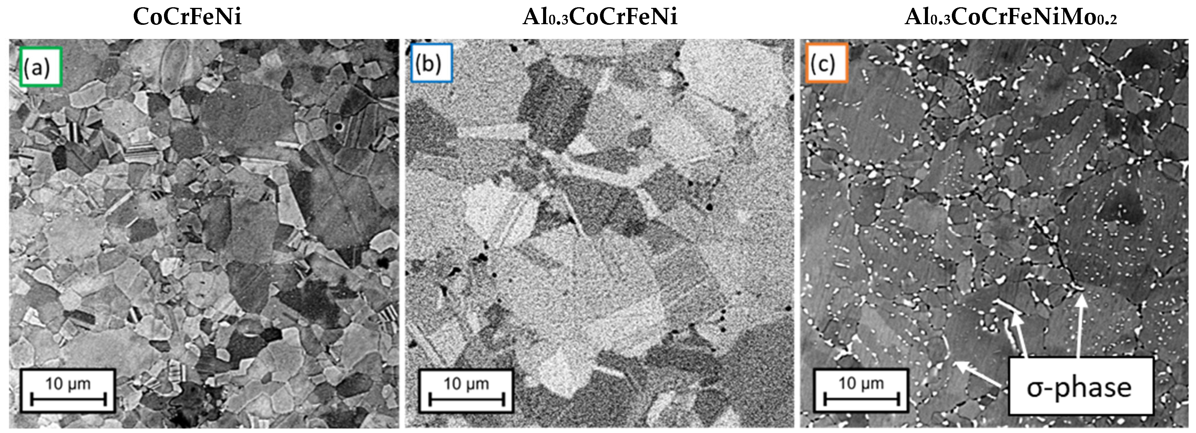
2.1. Material Preparation

Bulk materials of the MPEAs CoCrFeNi, Al0.3CoCrFeNi, and Al0.3CoCrFeNiMo0.2 were produced from metallurgical powder via spark plasma sintering (SPS). As feedstock, inert gas-atomized powder (Nanoval GmbH & Co. KG, Berlin, Germany) was used. With an SPS KCE FCT-HP D 25-SI (FCT Systeme GmbH; Frankenblick, Germany), the feedstock powder was compacted into bulk alloys with a diameter of 40 mm and a height of 6 mm. For the production of the bulk alloys, graphite tools consisting of two graphite punches, one graphite die, and two graphite cones were used. Graphite foils with a thickness of 0.3 mm were inserted between the feedstock and the punches as well as the die. Reactions with the atmosphere were prevented by flushing the recipient with argon and evacuating it twice (<1 mbar). The consolidation was carried out under a pressure of 50 MPa, at a temperature of 1050 °C and a holding time of 10 min. The cooling was carried out at a cooling rate of approx. 150 K/min up to 573.15 K via water cooling system at the stamps.
The sintered pieces had a disc-like shape and were cut via electric discharge machining (EDM) to produce specimens for further machining by milling with the dimensions 14 × 14 mm2 and thickness 2 mm. One specimen from each alloy was prepared for metallographic analysis, and the microstructures are shown in Figure 1. At this magnification, the CoCrFeNi and Al0.3CoCrFeNi alloys show a single-phase columnar grain microstructure, while the Al0.3CoCrFeNiMo0.2 alloy shows the segregation of a bright intergranular Mo–Cr rich σ-phase, as reported in [15].
The chemical composition for these alloys was measured in representative areas via EDX. Although this does not provide accurate quantitative data of composition, the atomic percentage (at.%) results are shown as an approximation in Table 1. The composition of the CoCrFeNi alloy shows unexpected Al content.

2.2. Milling Experiments

The milling experiments were carried out under dry conditions using a five-axis machining center (“DMG MORI” DMU65) modified for the ultrasonic-assisted milling (USAM) process. An unused right-hand ball-nose-end milling tool with four cutting edges according to DIN 6527 [31] was used for the full design of experiments on each alloy. The tools provided by WOLF Werkzeugtechnologie GmbH were made of cemented carbide (tungsten carbide in cobalt matrix) coated by physical vapor deposition (PVD) with an AlTiCrN layer (2–3 µm). The diameter was 6 mm, with a relief angle of 15°, helix angle of 30°, and rake angle of 4°. The tool geometry and coating were designed for the finish milling of hard-to-machine Ni-based alloys such as IN718, and therefore was expected to perform well for these alloys, with similarities in chemistry but lower hardness values. Figure 2a shows the experimental setup for the milling experiments with the equipment for the in-situ measurements of cutting forces and temperatures on the tool edge. Figure 2b shows a close-up of the tool–workpiece orientation with a description of the tool kinetics and definition of the axes of experimental setup.

2.3. Design of Experiment (DoE)

The experiments carried out aimed to isolate the influence of different parameters of the milling experiment on the finished surface. The parameters assessed are the cutting speed (vc), the feed per cutting edge (fz), and the use of ultrasonic (US) assistance. The use of vc and fz to define the machining conditions (instead of tool rotation or feed velocity) allow us to reproduce the experiments with different tool geometries and maintain comparability.
In Table 2, the full design of the experiment carried out on each alloy is shown. The experiment consists of milling 12 specimens of 14 × 14 mm2 with a cut depth of 0.3 mm for a material-removal volume per specimen of ≈60 mm3 and a full DoE milling ≈ 720 mm3 with the same cutting tool. For Ni-based alloys, the dry-cutting conditions recommended by the tool manufacturer were set as control experiments (marked with *). They were chosen to maintain the tool orientation, down-milling mode, cutting depth ap, and stepover ae constant, with the recommended parameters from the tool manufacturer set for the reduction in the scope of the experiment. The tool inclination in the x- (feed angle λ) and y- (tilt angle τ) directions were fixed at 45°, with a resulting angle β over the sample surface of 54.7°, calculated according to [32]. This prevents cutting with the tip of the nose, therefore avoiding the lowest cutting-speed points of the tool edge. The cutting speed vc and feed per cutting edge fz were varied systematically during the experiment, combining low and high vc (30–110 m/min) with low and high fz (0.04–0.07 mm), and all milling conditions were examined, both in conventional milling (0% USAM) and ultrasonic-assisted milling (100% USAM). Due to the ball-shaped tool, the cutting speed was not constant along the cutting edges, and vc refers to the maximum relative speed between the tool and workpiece. The design of the experiments used was already described in [20,23]. To avoid systematic errors, e.g., by heat generation, the central-point tests were performed twice to examine the reproducibility, with those under conventional milling placed as first and last in the experiment to assess the effect of tool wear. In between the two points, the test order was established randomly.
The ultrasonic oscillation was approximately 3 µm, selected as a maximum value with a given ultrasonic actor, at resonance frequency, which depends on the tool weight and cutting conditions. The value of this frequency measured was fUS ~40 kHz during the experiments on CoCrFeNi, Al0.3CoCrFeNi, and Al0.3CoCrFeNiMo0.2 alloys, respectively.
In situ measurements of cutting forces and temperatures were carried out for each sample during milling at two different positions. A Kistler dynamometer type 9139AA was used to measure cutting forces (Ff, feed force; FfN, normal feed force; and Fp, passive force). A high-speed pyrometer KLEIBER 740, with a sample interval around 6 µs and an emissivity of 0.1, was used to measure the temperatures on the tool’s cutting edge upon exit from the workpiece. After due calibration, the pyrometer detected infrared radiation from temperatures above 127 °C; therefore, only temperatures over this value were measured. The pyrometer was calibrated on the tool surface/coating by heating the tool by induction and counter measuring the temperature with a type K thermocouple. The maximum local temperatures reached in the flank face during each cutting motion can be higher than the measurements obtained, given the positioning of the pyrometer at the tool edge upon exit from the workpiece, but are still a good approximation to the maximum temperatures on the tool and allow for comparability between milling conditions.

2.4. Analysis

The data acquired (raw data shown in Figure 3) were smoothed to reduce noise in the measurement, necessary for the postprocessing of the data to perform correct peak identification. In addition, any possible offset in the measurements was subtracted. The dynamometer signal is composed of force measured in three perpendicular directions: the feed force Ff, the normal feed force FfN, and the passive force Fp (see [27]). The total force Ft is calculated according to Equation (1):
F t = F f 2 + F f N 2 + F p 2  
and a peak identification for the local maxima is run to find the maximum total force in each cutting motion of the tool. Later, a statistical analysis is carried out over all peaks to find the resulting cutting force Fres, as the average of maximums of all peaks.
The data acquired with the pyrometer were treated similarly, obtaining a resulting temperature Tr that was used for the analysis of results. For each alloy, the milled samples were topographically analyzed by means of scanning-electron microscope (SEM, Phenom XL, Thermo Fisher Scientific, Berlin, Germany) and light-optical microscopy (LOM, Keyence VHX-7000, Neu-Isenburg, Germany). Tactile roughness measurements were carried out in x- and y-directions with a contact profilometer (Hommel-Etamic T1000, Jenoptik, Jena, Germany) according to DIN EN ISO 4287 [33].

3. Results

3.1. Milling Process

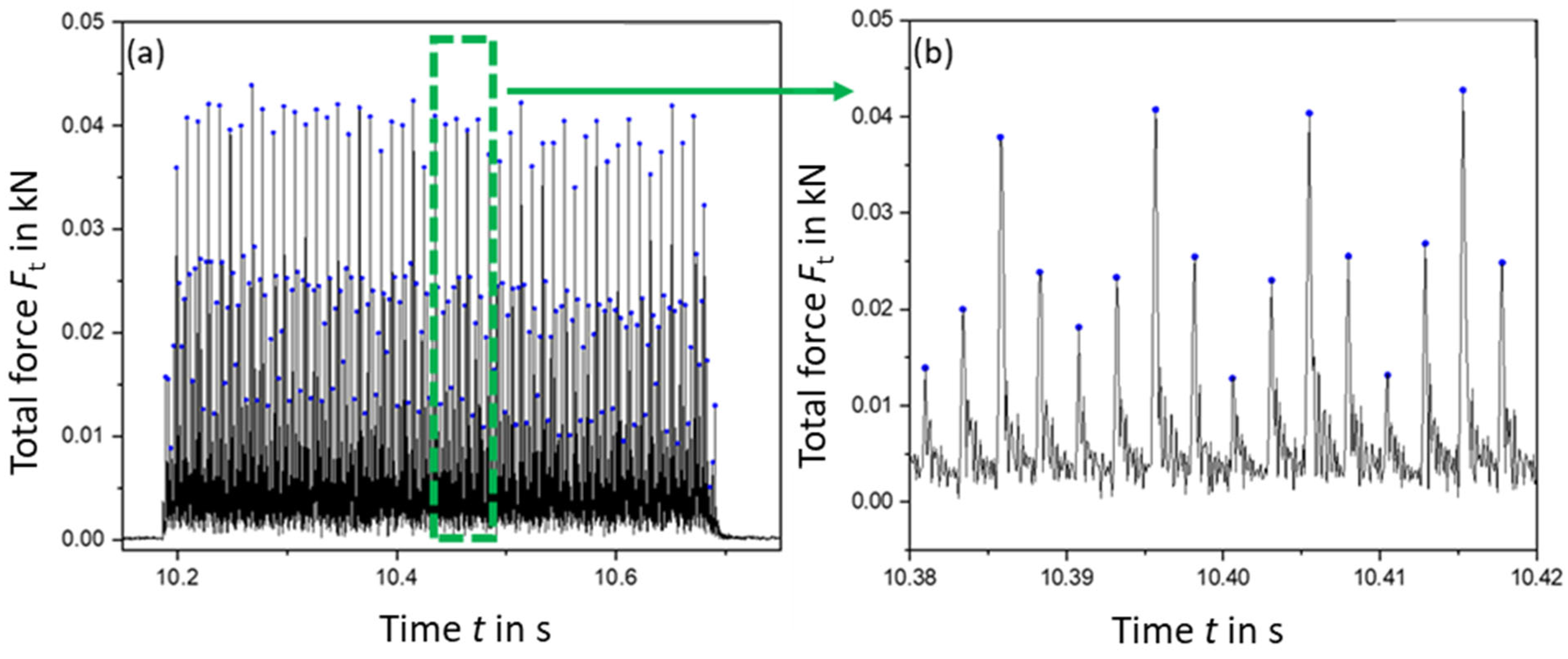
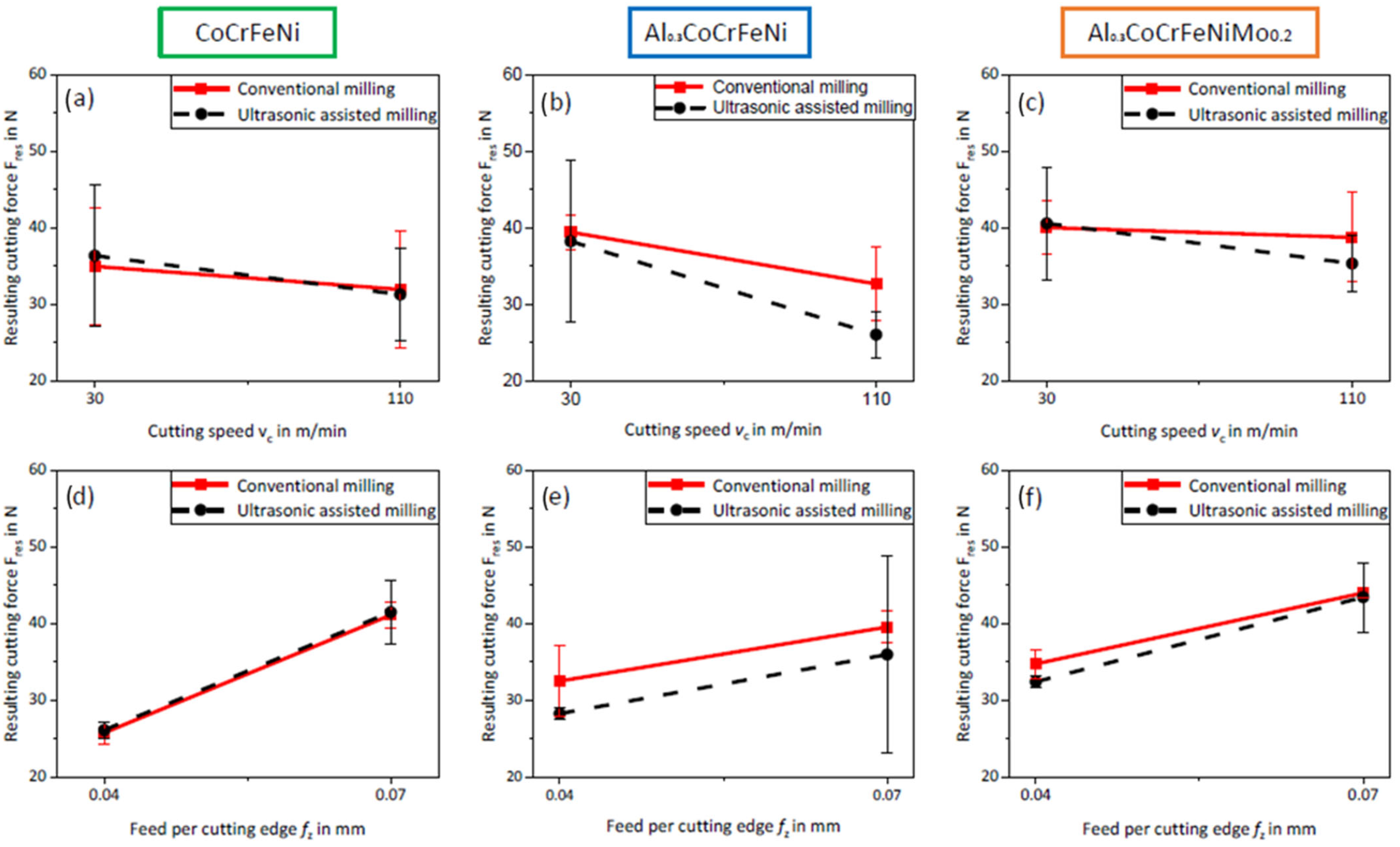
3.1.1. Cutting Force

To assess the influences of cutting speed, feed per cutting edge, and the use of ultrasonic assistance separately, specific effect diagrams are shown in Figure 4 for each alloy. Here, the connection of the described points should support the effect representation and not represent a linear connection. Figure 4a–c show the influence of cutting speed on the resulting force for CoCrFeNi, Al0.3CoCrFeNi, and Al0.3CoCrFeNiMo0.2, respectively. In these diagrams, all experiments performed at low vc (30 m/min) have been averaged and compared to those performed at high vc (110 m/min). A tendency to reduce cutting forces with increasing cutting speed is shown in all three diagrams and is especially significant (effect greater than the standard deviations) for the Al0.3CoCrFeNi alloy under conventional milling. Milling at high speed generally leads to higher temperatures, and a localized increase in temperature can promote thermal softening, causing ductility to increase and allow for greater shear deformation under lower cutting force [34]. A similar influence of cutting speed was reported in [23] for the Cantor alloy in the range of cutting speeds investigated.
The influence of feed per cutting edge on the resulting force is shown in Figure 4d–f. In these diagrams; all experiments performed at low fz (0.04 mm) have been averaged and compared to those performed at high fz (0.07 mm). Feed per cutting edge shows significant effect in all cases, except for the Al0.3CoCrFeNi under USAM. This is due to the low value of forces reported in experiment no. 2 for this alloy. Increasing fz between 0.04 and 0.07 mm led to an average increase in Fres by approximately 30% for the Al0.3CoCrFeNi and Al0.3CoCrFeNiMo0.2 alloys and by 60% for the CoCrFeNi alloy.
This influence of feed per cutting edge is consistent with the current theory of cross-section of undeformed chip by Kundrák et al. [35], which states that the forces necessary to cut off a chip from the workpiece increase for a larger section of cut. However, for the Al0.3CoCrFeNi, a minimum in force was found at high cutting speed and high feed per cutting edge under USAM. The low value reported is the reason for the larger error observed at high feed per cutting edge under USAM for this alloy. This is due to a high rate of work hardening in this alloy, which is reported in [36]. At low feed per cutting edge, the tool may be cutting over a strain-hardened subsurface, which is avoided at higher feed. However, this has not been proven, and the effect is only observed at high cutting speed under USAM for this alloy.
Regarding the deviation bars shown in the effect diagrams below, it is observed that these tend to be larger for the cutting speed comparison in Figure 4a–c than the feed per cutting edge comparison in Figure 4d–f. The effect is shown for each cutting velocity value investigated, by averaging two experiments with low and high feed per cutting edge. Since feed per cutting edge is the most influential parameter on cutting forces, the scatter is higher than in the feed per cutting edge comparison, except in Figure 5e, due to the low force value reported for Al0.3CoCrFeNi under USAM at high feed per cutting edge and high cutting speed.
The most significant influence of ultrasonic assistance was found in the Al0.3CoCrFeNi alloy, with ultrasonic assistance reducing cutting forces at low and intermediate feed per cutting edge and intermediate and high cutting speed. US assistance showed little or no significant influence on Fres for the CoCrFeNi alloy, shown in Figure 5a,c. This could be due to the inhomogeneity of its microstructure because of the hard Al-Ni-rich inclusions. On the Al0.3CoCrFeNiMo0.2 alloy, it showed a tendency to reduce cutting forces using USAM at high cutting speed.
Reductions in cutting forces have been reported on USAM of Inconel alloys [24,25,27] and the Cantor alloy [23], and attributed to reduced contact time and, therefore, less friction in the cutting process [37], as well as the effect of acoustic softening [38,39]. Selecting the machining conditions with the lowest cutting forces (typically fz = 0.04 mm and vc = 110 m/min under USAM) may benefit the reduction in power usage as well as reduce load on the tool and possibly extend tool life. However, this latter conclusion requires further analysis by means of tool-life testing, which is outside of the scope of this work.

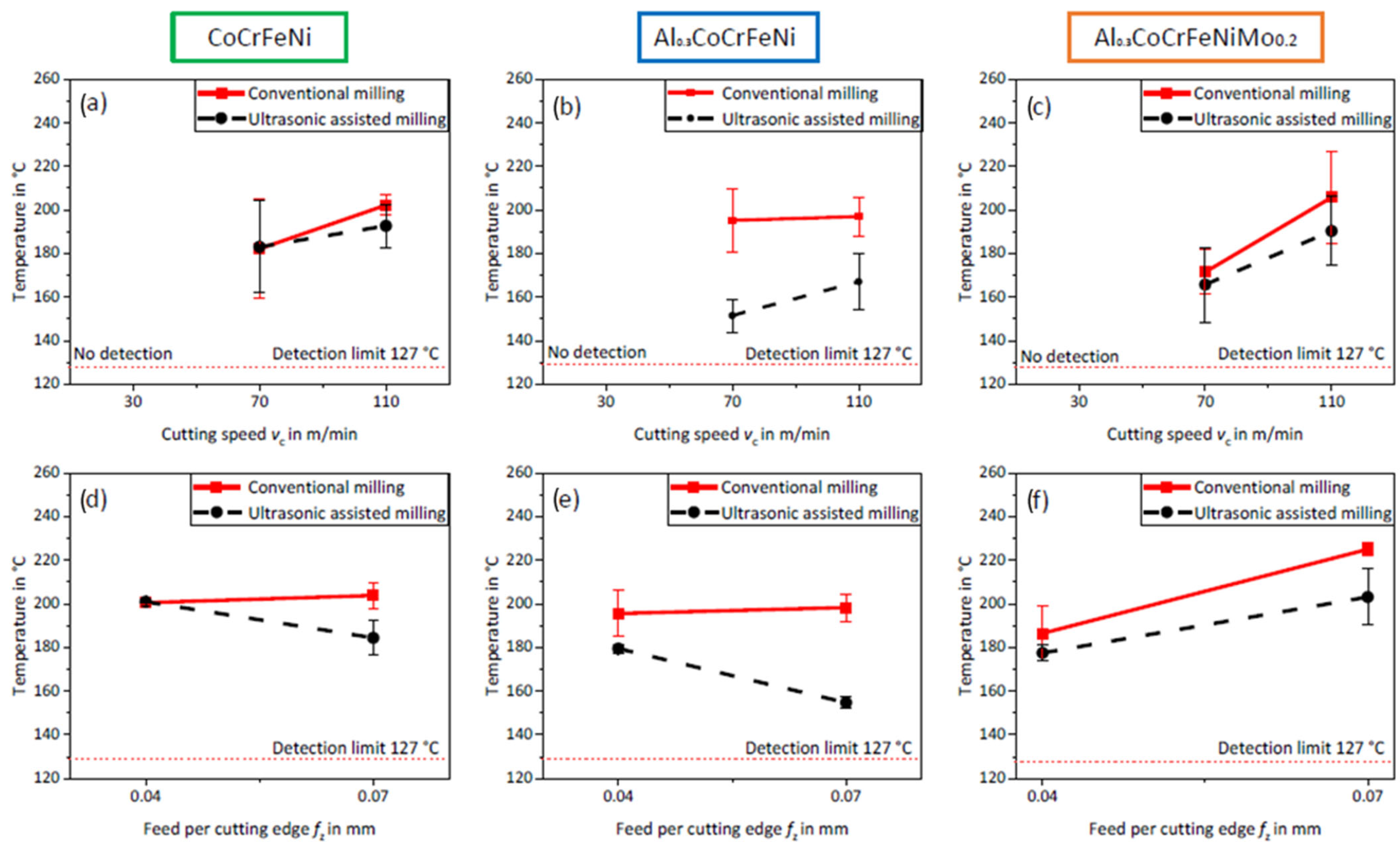
3.1.2. Process Temperatures

Figure 5a–c show the influence of cutting speed by averaging all experiments performed at the same vc. Since the experiments at the lowest cutting speed of 30 m/min did not reach the detection limit of the used high-speed pyrometer at 127 °C, the results from the control point at vc = 70 m/min are shown. However, the feed per cutting edge at vc = 70 m/min is 0.055 mm, and at vc = 110 m/min, the results for fz = 0.04 and 0.07 mm are averaged. Therefore, the comparability between the intermediate and high cutting speeds is limited.
Increasing cutting speed leads to increasing temperature, starting below 127 °C at 30 m/min and reaching maximums over 200 °C at 110 m/min under conventional milling for all three alloys. During the cutting process, kinetic energy from the tool motion is consumed by elastic deformation, plastic deformation at the shear plane, and friction, and is converted into heat [40]. A higher cutting speed means a higher shear deformation rate and, therefore, a greater heat power generated due to shear plane deformation. Due to the low thermal conductivity of these alloys [12], heat dissipation is slow, and the temperature rises locally. As a result, the process temperature increases with increasing cutting speed, as reported for several Ni-base materials [41,42], with a similar thermal conductivity [12] to the three alloys in the present study.
Figure 5d–f show the influence of feed per cutting edge only on the experiments carried out at high cutting speed (vc = 110 m/min), since no data were available at vc = 30 m/min. At high cutting speed, the CoCrFeNi and Al0.3CoCrFeNi alloys showed no significant influence of fz under conventional milling, reporting values from 200 to 205 °C. Under USAM conditions, increasing feed per cutting edge from 0.04 to 0.07 mm showed a reduction in temperature by 15 to 20 °C in these alloys. In Al0.3CoCrFeNiMo0.2, increasing fz led to an increase in temperatures from 180 °C to 210 °C.
According to the theoretical model proposed by Verma et al. [38], increasing fz leads to higher process temperatures. This is due to an increased area of the shear plane and a longer milled length by each cut of the tool edge on the workpiece, both effects causing higher heat generation and temperature rise. The results from the Al0.3CoCrFeNiMo0.2 alloy are in accordance with this model, with higher feed per cutting edge leading to higher temperatures. However, in the CoCrFeNi and Al0.3CoCrFeNi alloys, no influence under conventional milling was observed, and a reduction in temperatures at increasing fz was reported under USAM. A reasonable explanation is that there is an increased heat transfer into the chip at high feed rate (larger chip size), and, therefore, the value of the temperature measured at the cutting edge of the tool is lower. The use of USAM tends to cause a reduction in temperature in comparison to conventional milling, which is especially significant at high speed and feed per cutting edge in all three alloys, going from 205 °C to 185 °C in the CoCrFeNi; from 200 °C to 155 °C in the Al0.3CoCrFeNi; and from 230 °C to 205 °C in the Al0.3CoCrFeNiMo0.2. The Al0.3CoCrFeNi alloy showed the highest reductions in temperatures due to US assistance.
The reductions in temperatures observed are in accordance with the theoretical model proposed by Verma et al. [43], in which the intermittent cutting process induced by ultrasonic vibration on the tool leads to a decreased contact ratio and decrease in total generated heat. The introduction of acoustic softening by the ultrasonic vibration contributes additionally to lower process temperatures.
High temperatures during the milling process are to be avoided for several reasons. First, higher temperatures induce a higher depth of the plastically deformed layer in the first few micrometers of the workpiece, known as white layer. This region is typically affected by increased hardness and could (as a result) embrittle the workpiece [44], while also inducing higher wear out on the tool. In addition, the appearance of tensile residual stresses on the surface of the workpiece is largely due to local temperature gradient during machining [45], and the presence of higher tensile residual stresses on the surface is typically detrimental for manufactured components since it may enhance crack initiation and propagation [46].
Regarding the effects on the tool, high process temperatures accelerate diverse tool-wear mechanisms, such as abrasion, diffusion, and oxidation [47]. Furthermore, buildup edge (BUE) on the cutting tool forms preferentially under low cutting velocities, but thermal softening of the workpiece and adhesion mechanisms are enhanced at higher temperatures caused by high speeds [48]. BUE on the tool is undesired since it modifies the geometry of the edge, leading to poorer surface integrity.
The PVD AlTiCrN coating has high hardness and oxidation resistance and is designed to minimize the adhesion tendency. It has a maximum recommended process temperature of 800 °C. The highest resulting temperatures measured under the experimented conditions were around 230 °C. However, these are not necessarily the highest temperatures in the process, as the temperature is measured on the cutting edge upon its exit from the workpiece, and the highest temperatures are most likely found on the contact point between the rake face of the tool edge and the specimen [42]. Since these temperatures are not directly measured, it is not possible to confirm the maximum temperature to which the tool coating is exposed. However, Le Coz et al. [42] found maximum temperatures below the limit of the coating used for much higher cutting speeds in IN718. Therefore, regarding process temperatures on the tool, it is reasonable to declare the milling conditions that encompass high cutting speed as suitable, which, in turn, reduce forces and load on the tool.
Finally, the introduction of coolants or lubrication in the milling process would most likely help lower temperatures as well as cutting forces, as it has been reported for ball-nose-end milling of Inconel alloys [27]. Therefore, despite the environmental drawback from their use due to polluting elements and lubricant residue in manufactured components and evacuated chips [49], it would be of interest to investigate their effect on these novel alloys.

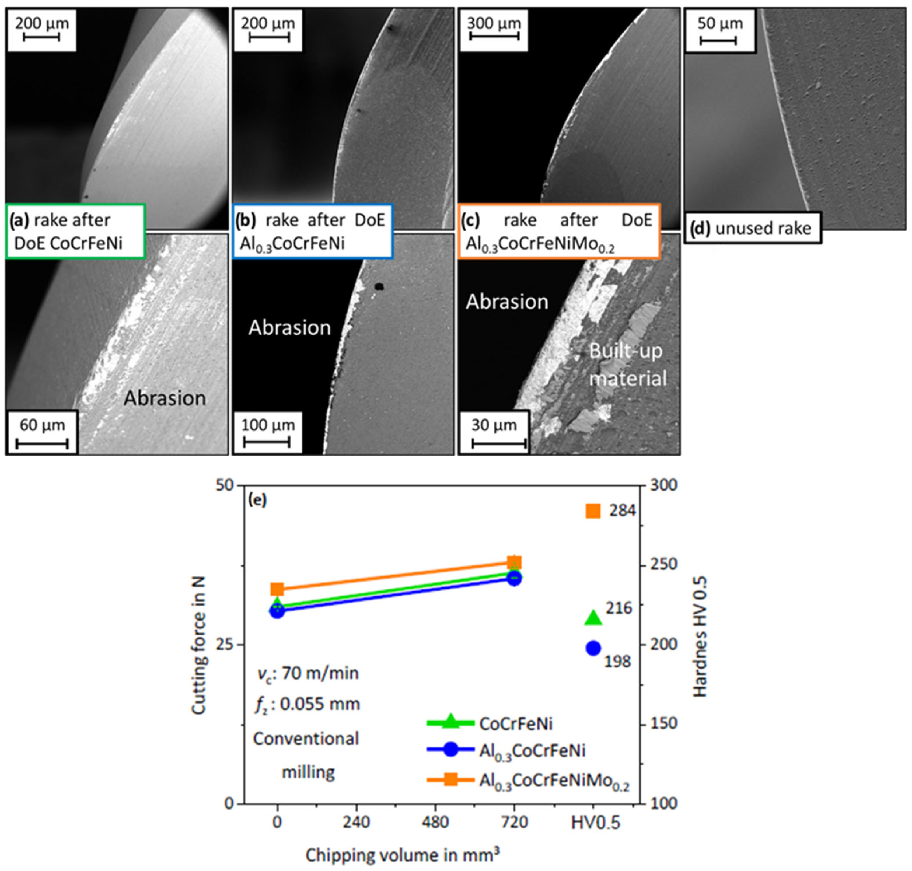
3.2. Effect on Tool Wear Out

Figure 6a–c show the state of the tool-edge rake face after the full round of experiments on each alloy, compared with an unused tool (Figure 6d), and the effect of variation in tool condition on cutting forces between the first and last experiments (Figure 6e). This shows a correlating relationship between the material hardness and the cutting forces, as the forces also increased with increasing hardness. For all three alloys, an abrasion-wear mechanism was observed, which took the PVD AlTiCrN coating off in the most affected region of the edge, revealing the tungsten carbide cobalt (WC-Co) substrate underneath, which appears bright under EBS imaging. For the Al0.3CoCrFeNiMo0.2, the adhesion of some material from the specimens to the rake face of the cutting edge was reported. The finding of a small build-up on the edge on the cutting tool is in accordance with the highest temperatures reported for this alloy, conditions which enhance the thermal softening of the workpiece and adhesion mechanisms to the tool edge [50].
Compared to a superalloy Inconel 718 where the average chip volume until wear is about 3200 mm3 [51], a full DoE accounts for approximately 700 mm3 of milled material. The tool wear observed accounts for moderate increases in cutting forces (≈15%–20%) and, therefore, it is considered that for the machining conditions experimented, the tool and coating material selected are acceptable. However, there is still great potential for improvement in tool adaptation and development for each individual alloy. For a more detailed analysis of tool performance, specific tool-life-testing experiments are necessary, which are outside of the scope of this work.

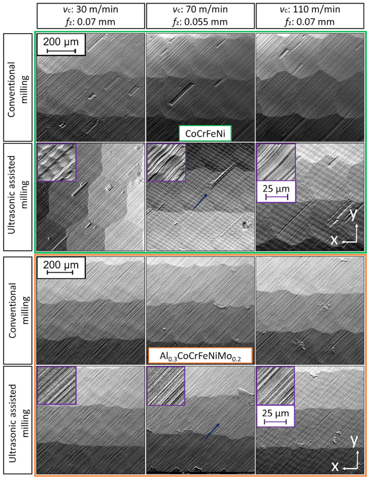
3.3. Surface Integrity

Figure 7 shows the light-optical-microscopy images under coaxial illumination of 1 × 1 mm2 surface areas of the milled alloys under low (30 m/min) and high (110 m/min) cutting speeds, as well as low (0.04 mm) and high (0.07 mm) feed per cutting edge. The typical surface topography generated by ball-nose-end milling was observed, with peaks and valleys resulting from each pass of a cutting edge over the workpiece, in accordance with [48]. The distance between milling lines in the stepover (y) direction was the same under all conditions and equal to the stepover value ap of 0.3 mm, which was kept constant during the experiment. The influence of increasing fz was seen on the topography as a larger width of valleys in the feed direction (x). The use of ultrasonic assistance was seen to leave a particular wavy pattern known as ultrasonic pattern, which has been previously reported [23,27].
The CoCrFeNi and Al0.3CoCrFeNiMo0.2 alloys showed a high amount of surface defects. Figure 8 shows EBS topography images for the CoCrFeNi and Al0.3CoCrFeNiMo0.2 alloys, comparing the combined influence of cutting speed and ultrasonic assistance on the milled surfaces, and showing the combined effect of these parameters on the resulting surface. This pattern is easily recognizable at high cutting speeds, due to the high frequency of US assistance at approx. 40 kHz, which (at low cutting speed) results in a very fine pattern not distinguishable at low magnification.
For the CoCrFeNi alloy, grooves and tear defects were identified in all cutting conditions, marked in red (Figure 7). A significant variation in their presence depending on milling conditions was not observed. These surface defects are attributed to the milling tool passing over a hard Al-Ni-rich particle like the ones shown in Richter et al. [30] for the same CoCrFeNi alloy samples. Similar tear and groove defects were found in ball-nose-end milling experiments on CoCrFeMnNi [23] due to the presence of hard oxide particles. The appearance of such surface defects has also been reported due to carbide particles in Inconel alloys [48,52].
We confirmed the observed tears and grooves in the same samples by Richter et al. [30]. The samples showed the presence of an Al-Ni-rich particle on the surface, which was cut by the tool edge and carried in the direction of the tool rotation, leaving a groove defect with particle debris. The presence of these defects is highly detrimental to the surface integrity of the material since they are preferential sites for crack initiation or pitting corrosion [53]. In addition, the interaction between the hard particles and tool edge leads to higher stresses in the workpiece material around the particle. This can lead to higher residual stresses in the workpiece material and can induce higher abrasion on the tool coating and accelerate tool wear.
For the Al0.3CoCrFeNiMo0.2 alloy, a large number of defects consisting of built-up material deposited on the surface were observed. These surface defects, known as BUE defects, have their origin in the workpiece material adhering to the tool edge and forming a built-up edge on the tool. Later, due to friction between the tool edge and workpiece, this material can be detached from the edge and deposited on the machined surface [50]. The appearance of BUE defects on the surface of the Al0.3CoCrFeNiMo0.2 alloy is in accordance with the finding of workpiece material deposited on the tool edge of the ball-nose-end milling cutter used for this alloy, as seen in Figure 6. No influence of feed per cutting edge or the use of ultrasonic assistance was observed on the frequency of BUE surface defects. However, increasing cutting speed showed a higher frequency of these defects. At the lowest vc of 30 m/min, no such defects were observed, at intermediate vc of 70 m/min, some of these defects appeared, and at the highest cutting speed of 110 m/min, they were found with the highest frequency.
The underlying mechanism is caused by the increased heat generation at increased cutting speed, as an important thermal softening of the workpiece appears and adhesion mechanisms to the tool edge are also enhanced, favoring the formation of BUE on the tool. At the same time, high temperatures favor the material adhered to the cutting edge to stick to the machined surface and form the BUE surface defect. Regarding the effect of feed per cutting edge, increasing fz potentially leads to higher temperatures which promote plastic deformation; however, at the same time, it decreases the ploughing area, which in turn lowers the possibility of a built-up edge [50]. Under the competing effect of these two factors, no significant influence of fz was observed. The influence of cutting speed and feed per cutting edge on the frequency of BUE defects observed is in accordance with the results in [48] on surface defects on IN718. The appearance of BUE defects was, in that study, directly related to temperature, and therefore most significant at high cutting speeds. No concrete statement on the US influence on the formation or number of surface defects can be derived from the results presented.
A quantitative analysis of the surface finish was carried out by means of the mean roughness depth parameter Rz obtained from the surface profiles measured in the feed and stepover directions. Figure 9 shows effect diagrams of the influence of cutting speed and feed per cutting edge on Rz in both feed and stepover directions. Rz shows a range of average values between 2.2 and 4.2 µm in the feed direction and between 4 and 5 µm in the stepover direction. For the discussion of these results, Rz was compared with a theoretical prediction Rzth [54] calculated using geometrical considerations of the process, such as tool geometry and orientation, feed per cutting edge, and depth of cut, and the comparison is shown in Table 3. The first observation is that experimental values are consistently higher than theoretical predictions due to deviations from ideality in the process, such as tool deflection and vibrations, according to Nespor et al. [54].
The theoretical roughness Rzth in the stepover direction was higher than in the feed direction, due to an ap = 0.3 mm and fz between 0.04 and 0.07 mm, which is in accordance with consistently higher values reported in the stepover direction than in the feed direction. However, the differences predicted by Table 3 between feed and stepover directions are by several orders of magnitude higher. This is because of the experimental values for Rz in the feed direction (ranging from 2.5 to 4 µm), which have higher deviations with corresponding Rzth (0.07 to 0.20 µm) at low feed per cutting edge, magnify the deviations from ideality in the geometry of the tool edge.
Regarding the influence of cutting speed, increasing vc from 30 to 110 m/min showed a tendency to increase roughness, which is most significant in the stepover direction. The influence is most remarkable for the CoCrFeNi alloy, with increased from 4 to 5 µm in Rz under USAM. The increases in roughness in the stepover direction with increasing cutting speed are attributed to deviations from the ideal cutting process, in the form of larger vibrations and tool deflection introduced by higher cutting speeds [54].
Increasing Rz in the feed direction at increasing fz is in accordance with geometrical considerations of the generated surface, predicted in Table 3. No significant increase appearing for Al0.3CoCrFeNiMo0.2 is attributed to a slight decreased depth of cut, in agreeance with its lower roughness values in comparison with the other two alloys. The reason for this is a significant tool deflection due to the higher hardness of the alloy. In the stepover direction, feed per cutting edge was shown to have no significant influence on the roughness parameters, with a constant average Rz around 4.5 µm. This is in accordance with geometrical considerations of the generated surface, which, in addition to tool diameter and orientation, depends only on the stepover ap.
The use of ultrasonic assistance also shows a tendency to increase the value of roughness parameters; however, in most cases, the difference between conventional milling and ultrasonic-assisted milling is below the standard deviation. A tendency towards increased roughness under USAM is justified in the wavy ultrasonic pattern from the high-frequency axial vibration of the tool. Suárez et al. reported such increased roughness values by means of US assistance in comparison to conventional milling in the face turning of IN718 [55]. However, the effect observed from these results is low, similar to that reported in [23] on ball-nose-end milling of the CoCrFeMnNi alloy, with no considerable influence of ultrasonic assistance on the final roughness.

4. Conclusions

The AlTiCrN PVT-coated ball-nose-end milling tool had a good performance on the CoCrFeNi, Al0.3CoCrFeNi, and Al0.3CoCrFeNiMo0.2 alloys in the range of cutting parameters recommended by the tool manufacturer under dry conditions. Tool wear after milling 720 mm3 under varying conditions was moderate, leading to increases in cutting forces by 15% to 20%.
  • Cutting forces were minimized by using high cutting speed (110 m/min) and low feed per cutting edge (0.04 mm). The use of ultrasonic assistance showed a positive influence in reducing cutting forces.
  • Increasing cutting speed led to increasing temperature on the tool edge. In comparison with conventional milling, the use of ultrasonic assistance led to a reduction in temperatures, especially significant at the conditions with the highest temperatures.
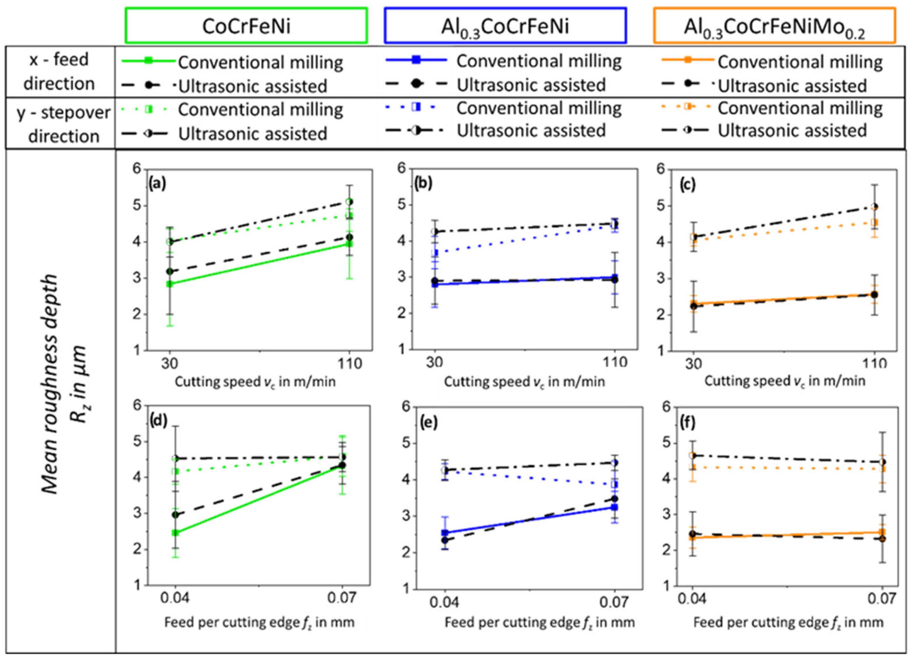
  • Roughness parameters in the feed direction increased with increasing feed per cutting edge, according to expected geometry of the finished surface.
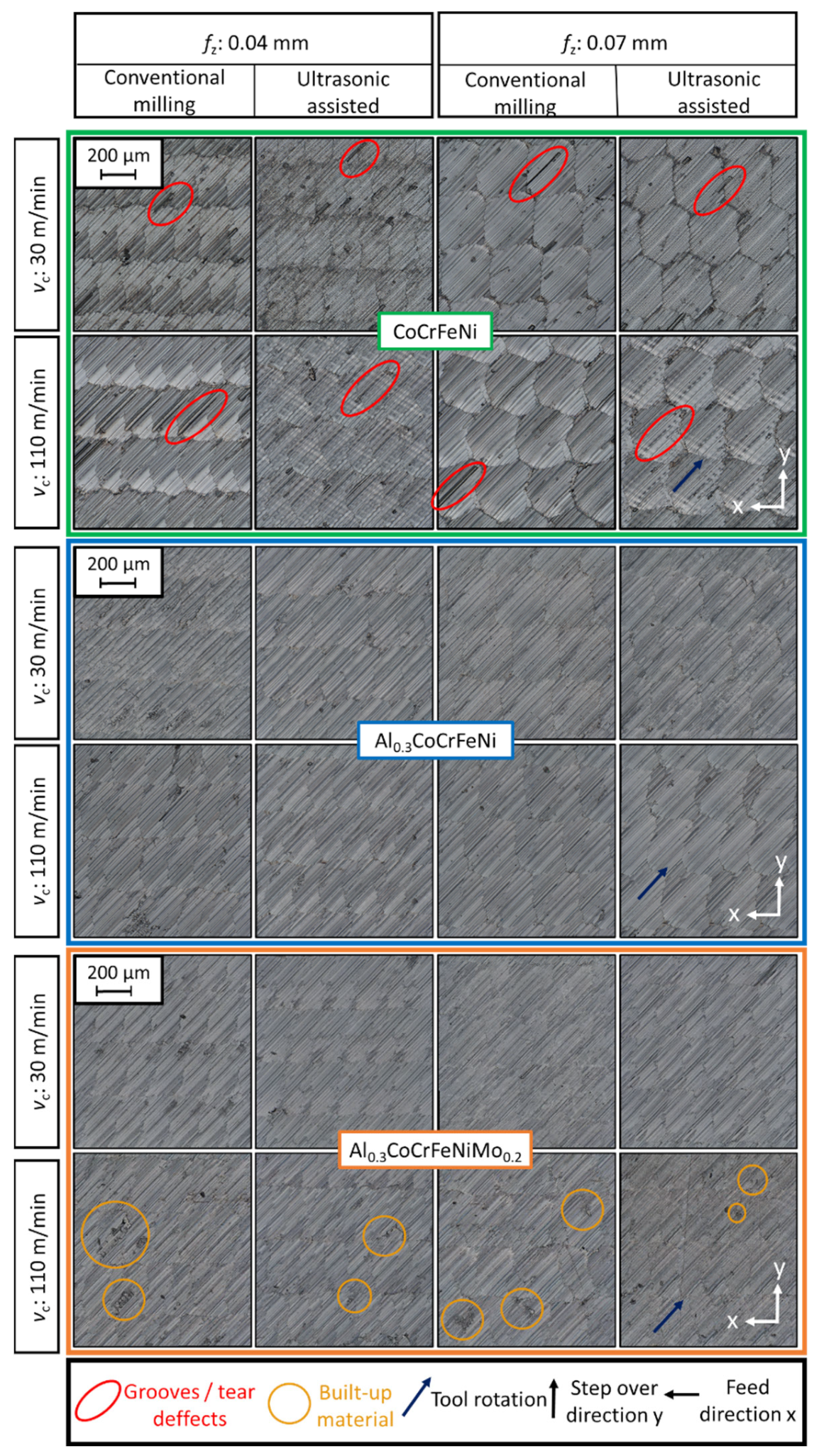
  • The presence of hard particles in CoCrFeNi enhanced tool deflection and vibrations, leading to significantly higher roughness at higher cutting speed, and resulted in a high population of grooves and tear defects on the machined surface, which can be detrimental to the surface integrity.
  • The Al0.3CoCrFeNiMo0.2 showed redeposited material on the milled surface as built-up edge defects at increased cutting speed, in accordance with the built-up edge observed on the tool edge, and the highest temperatures were reported for this alloy.
  • The Al0.3CoCrFeNi alloy reported the highest quality of surface finish in terms of frequency of surface defects, correlating with the lowest hardness and cutting forces, as well as a microstructure free of hard inclusions or precipitates.
This work shows that common theories in machining can be transferred to these novel MPEAs. The milling conditions of low cutting speed (30 m/min) and low feed per cutting edge (0.04 mm) under ultrasonic assistance report moderate cutting forces and low temperatures. These conditions are optimal for the extension of tool life and improved surface integrity by reducing roughness parameters, surface defects, and thermal affection of the workpiece.
The conclusions drawn from this work allow us to characterize the influence of different machining parameters on different surfaces. However, for future research, it would be interesting to conduct subsurface analysis to determine the effect of machining parameters on subsurface deformation and, potentially, the early introduction of compressive residual stresses into the workpiece by means of ultrasonic assistance.

Author Contributions

Conceptualization: D.D.A. and T.R.; investigation: D.D.A., A.B. and T.R.; data curation: D.D.A.; writing—original draft preparation: D.D.A.; writing—review and editing: T.R., D.S., M.R., B.P. and T.L. (Thomas Lindner); supervision: D.S., M.R. and T.L. (Thomas Lampke); funding acquisition: M.R., D.S. and T.L. (Thomas Lindner). All authors have read and agreed to the published version of the manuscript.

Funding

The authors gratefully acknowledge the financial support by the Sächsische Aufbaubank-Förderbank/SAB-100382175 by the European Social Fund ESF and the Free State of Saxony. Coatings 13 00662 i001

Institutional Review Board Statement

Not applicable.

Informed Consent Statement

Not applicable.

Data Availability Statement

Not applicable.

Acknowledgments

The authors want to thank Daniel Stock of the BAM Department 9.2 for the support in the experimental work of the machining tests.

Conflicts of Interest

The authors declare no conflict of interest.

References

  1. Yeh, W.; Chen, S.K.; Lin, S.J.; Gan, J.Y.; Chin, T.S.; Shun, T.T.; Tsau, C.H.; Chang, S.Y. Nanostructured high-entropy alloys with multiple principal elements: Novel alloy design concepts and outcomes. Adv. Eng. Mater. 2004, 6, 299–303. [Google Scholar] [CrossRef]
  2. Cantor, B.; Chang, I.T.H.; Knight, P.; Vincent, A.J.B. Microstructural development in equiatomic multicomponent alloys. Mater. Sci. Eng. A 2004, 375–377, 213–218. [Google Scholar] [CrossRef]
  3. Ranganathan, S. Alloyed pleasures: Multimetallic cocktails. Curr. Sci. 2003, 85, 1404–1406. [Google Scholar]
  4. Gao, M.C.; Yeh, J.-W.; Liaw, P.K.; Zhang, Y. High-Entropy Alloys Fundamentals and Applications; Springer International: Basel, Switzerland, 2016. [Google Scholar] [CrossRef]
  5. Manzoni, A.M.; Glatzel, U. High-Entropy Alloys: Balancing Strength and Ductility at Room Temperature. In Reference Module in Materials Science and Materials Engineering; Elsevier Inc.: Amsterdam, The Netherlands, 2020. [Google Scholar] [CrossRef]
  6. Torbati-Sarraf, H.; Shabani, M.; Jablonski, P.D.; Pataky, G.J.; Poursaee, A. The influence of incorporation of Mn on the pitting corrosion performance of CrFeCoNi High Entropy Alloy at different temperatures. Mater. Des. 2019, 184, 108170. [Google Scholar] [CrossRef]
  7. Wang, W.-R.; Wang, W.-L.; Yeh, J.-W. Phases, microstructure and mechanical properties of AlxCoCrFeNi high-entropy alloys at elevated temperatures. J. Alloys Compd. 2014, 589, 143–152. [Google Scholar] [CrossRef]
  8. Wu, Z.; Bei, H.; Pharr, G.M.; George, E.P. Temperature dependence of the mechanical properties of equiatomic solid solution alloys with face-centered cubic crystal structures. Acta Mater. 2014, 81, 428–441. [Google Scholar] [CrossRef]
  9. Liu, J.; Guo, X.; Lin, Q.; He, Z.; An, X.; Li, L.; Liaw, P.K.; Liao, X.; Yu, L.; Lin, J.; et al. Excellent ductility and serration feature of metastable CoCrFeNi high-entropy alloy at extremely low temperatures. Sci. China Mater. 2018, 62, 853–863. [Google Scholar] [CrossRef] [Green Version]
  10. Wang, W.-R.; Wang, W.-L.; Wang, S.-C.; Tsai, Y.-C.; Lai, C.-H.; Yeh, J.-W. Effects of Al addition on the microstructure and mechanical property of AlxCoCrFeNi high-entropy alloys. Intermetallics 2012, 26, 44–51. [Google Scholar] [CrossRef]
  11. Kao, Y.-F.; Chen, T.-J.; Chen, S.-K.; Yeh, J.-W. Microstructure and mechanical property of as-cast, -homogenized, and -deformed AlxCoCrFeNi (0 ≤ x ≤ 2) high-entropy alloys. J. Alloys Compd. 2009, 488, 57–64. [Google Scholar] [CrossRef]
  12. Chou, H.-P.; Chang, Y.-S.; Chen, S.-K.; Yeh, J.-W. Microstructure, thermophysical and electrical properties in AlxCoCrFeNi (0 ≤ x ≤ 2) high-entropy alloys. Mater. Sci. Eng. B 2009, 163, 184–189. [Google Scholar] [CrossRef]
  13. Shun, T.-T.; Du, Y.-C. Microstructure and tensile behaviors of FCC Al0.3CoCrFeNi high entropy alloy. J. Alloys Compd. 2009, 479, 157–160. [Google Scholar] [CrossRef]
  14. Li, C.; Li, J.C.; Zhao, M.; Jiang, Q. Effect of aluminum contents on microstructure and properties of AlxCoCrFeNi alloys. J. Alloys Compd. 2010, 504, S515–S518. [Google Scholar] [CrossRef]
  15. Rymer, L.M.; Frint, P.; Lindner, T.; Gebel, G.; Lobel, M.; Lampke, T. Strain-Rate Sensitive Deformation Behavior under Tension and Compression of Al0.3CrFeCoNiMo0.2. Adv. Eng. Mater. 2022, 24, 2100921. [Google Scholar] [CrossRef]
  16. Mane, R.B.; Panigrahi, B.B. Sintering mechanisms of mechanically alloyed CoCrFeNi high-entropy alloy powders. J. Mater. Res. 2018, 33, 3321–3329. [Google Scholar] [CrossRef]
  17. Löbel, M.; Lindner, T.; Hunger, R.; Berger, R.; Lampke, T. Precipitation Hardening of the HVOF Sprayed Single-Phase High-Entropy Alloy CrFeCoNi. Coatings 2020, 10, 701. [Google Scholar] [CrossRef]
  18. Guo, J.; Goh, M.; Zhu, Z.; Lee, X.; Nai, M.L.S.; Wei, J. On the machining of selective laser melting CoCrFeMnNi high-entropy alloy. Mater. Des. 2018, 153, 211–220. [Google Scholar] [CrossRef]
  19. Clauß, B.; Liborius, H.; Lindner, T.; Löbel, M.; Schnubert, A.; Lampke, T. Influence of the cutting parameters on the surface properties in turning of a thermally sprayed AlCoCrFeNiTi coating. Procedia CIRP 2020, 87, 19–24. [Google Scholar] [CrossRef]
  20. Richter, T.; Schröpfer, D.; Rhode, M.; Börner, A. Influence of modern machining processes on the surface integrity of high-entropy alloys. Symp. Mater. Join. Technol. 2020, 882, 012016. [Google Scholar] [CrossRef]
  21. Liborius, H.; Uhlig, T.; Clauß, B.; Nestler, A.; Lindner, T.; Schubert, A.; Wagner, G.; Lampke, T. Influence of the cutting material on tool wear, surface roughness, and force components for different cutting speeds in face turning of CoCrFeNi high-entropy alloys. IOP Conf. Ser. Mater. Sci. Eng. 2021, 1147, 012008. [Google Scholar] [CrossRef]
  22. Litwa, P.; Hernandez-Nava, E.; Guan, D.; Goodall, R.; Wika, K.K. The additive manufacture processing and machinability of CrMnFeCoNi high entropy alloy. Mater. Des. 2021, 198, 109380. [Google Scholar] [CrossRef]
  23. Richter, T.; Schroepfer, D.; Rhode, M.; Boerner, A.; Neumann, R.S.; Schneider, M.; Laplanche, G. Influence of machining on the surface integrity of high- and medium-entropy alloys. Mater. Chem. Phys. 2022, 275, 125271. [Google Scholar] [CrossRef]
  24. Fang, B.; Yuan, Z.; Li, D.; Gao, L. Effect of ultrasonic vibration on finished quality in ultrasonic vibration assisted micromilling of Inconel718. Chin. J. Aeronaut. 2021, 34, 209–219. [Google Scholar] [CrossRef]
  25. Nath, C.; Rahman, M. Evaluation of ultrasonic vibration cutting while machining Inconel 718. Int. J. Precis. Eng. Manuf. 2008, 9, 63–68. [Google Scholar]
  26. Ahmed, N.; Mitrofanov, A.V.; Babitsky, V.I.; Silberschmidt, V.V. Analysis of material response to ultrasonic vibration loading in turning Inconel 718. Mater. Sci. Eng. A 2006, 424, 318–325. [Google Scholar] [CrossRef]
  27. Schroepfer, D.; Treutler, K.; Boerner, A.; Gustus, R.; Kannengiesser, T.; Wesling, V.; Maus-Friedrichs, W. Surface finishing of hard-to-machine cladding alloys for highly stressed components. Int. J. Adv. Manuf. Technol. 2021, 114, 1427–1442. [Google Scholar] [CrossRef]
  28. Lotfi, M.; Charkhian, A.; Akbari, J. Surface analysis in rotary ultrasonic-assisted milling of CFRP and titanium. J. Manuf. Process. 2022, 84, 174–182. [Google Scholar] [CrossRef]
  29. Quin, S.; Zhu, L.; Wiercigroch, M.; Ren, T.; Hao, Y.; Ning, J.; Zhao, J. Material removal and surface generation in longitudinal-torsional ultrasonic assisted milling. Int. J. Mech. Sci. 2022, 227, 107375. [Google Scholar] [CrossRef]
  30. Richter, T.; Delgado Arroyo, D.; Boerner, A.; Schroepfer, D.; Rhode, M.; Lindner, T.; Loebel, M.; Preuß, B.; Lampke, T. Ultrasonic assisted milling of a CoCrFeNi medium entropy alloy. Procedia CIRP 2022, 108, 879–884. [Google Scholar] [CrossRef]
  31. DIN-6527; Vollhartmetall-Schaftfräser Mit Abgesetztem Zylinderschaft-Maße. Beuth Verlag GmbH DIN: Berlin, Germany, 2002.
  32. Denkena, B.; Nespor, D.; Böß, V.; Köhler, J. Residual stresses formation after re-contouring of welded Ti-6Al-4V parts by means of 5-axis ball nose end milling. CIRP J. Manuf. Sci. Technol. 2014, 7, 347–360. [Google Scholar] [CrossRef]
  33. DIN EN ISO 4287; Geometrische Produktspezifikation (GPS)—Oberflächenbeschaffenheit: Tastschnittverfahren—Benennungen, Definitionen und Kenngrößen der Oberflächenbeschaffenheit. Beuth Verlag GmbH DIN: Berlin, Germany, 2010.
  34. Gaikhe, V.; Sahu, J.; Pawade, R. Optimization of Cutting Parameters for Cutting Force Minimization in Helical Ball End Milling of Inconel 718 by Using Genetic Algorithm. Procedia CIRP 2018, 77, 477–480. [Google Scholar] [CrossRef]
  35. Kundrák, J.; Karpuschewski, B.; Pálmai, Z.; Felhő, C.; Makkai, T.; Borysenko, D. The energetic characteristics of milling with changing cross-section in the definition of specific cutting force by FEM method. CIRP J. Manuf. Sci. Technol. 2021, 32, 61–69. [Google Scholar] [CrossRef]
  36. Li, Z.; Zhao, S.; Diao, H.; Liaw, P.K.; Meyers, M.A. High-velocity deformation of Al0.3CoCrFeNi high-entropy alloy: Remarkable resistance to shear failure. Sci. Rep. 2017, 7, 42742. [Google Scholar] [CrossRef] [PubMed]
  37. Rinck, P.M.; Gueray, A.; Kleinwort, R.; Zaeh, M.F. Experimental investigations on longitudinal-torsional vibration-assisted milling of Ti-6Al-4V. Int. J. Adv. Manuf. Technol. 2020, 108, 3607–3618. [Google Scholar] [CrossRef]
  38. Verma, G.C.; Pandey, P.M.; Dixit, U.S. Modeling of static machining force in axial ultrasonic-vibration assisted milling considering acoustic softening. Int. J. Mech. Sci. 2018, 136, 1–16. [Google Scholar] [CrossRef]
  39. Verma, G.C.; Pandey, P.M. Machining forces in ultrasonic-vibration assisted end milling. Ultrasonics 2019, 94, 350–363. [Google Scholar] [CrossRef]
  40. Yan, S.; Zhu, D.; Zhuang, K.; Zhang, X.; Ding, H. Modeling and analysis of coated tool temperature variation in dry milling of Inconel 718 turbine blade considering flank wear effect. J. Mater. Process. Technol. 2014, 214, 2985–3001. [Google Scholar] [CrossRef]
  41. Ng, E.G.; Lee, D.W.; Sharman, A.R.C.; Dewes, R.C.; Aspinwall, D.K.; Vigneau, J. High Speed Ball Nose End Milling of Inconel 718. CIRP Ann. 2000, 49, 41–46. [Google Scholar] [CrossRef]
  42. Le Coz, G.; Dudzinski, D. Temperature variation in the workpiece and in the cutting tool when dry milling Inconel 718. Int. J. Adv. Manuf. Technol. 2014, 74, 1133–1139. [Google Scholar] [CrossRef]
  43. Verma, G.C.; Pandey, P.M.; Dixit, U.S. Estimation of workpiece-temperature during ultrasonic-vibration assisted milling considering acoustic softening. Int. J. Mech. Sci. 2018, 140, 547–556. [Google Scholar] [CrossRef]
  44. Ulutan, D.; Ozel, T. Machining induced surface integrity in titanium and nickel alloys: A review. Int. J. Mach. Tools Manuf. 2011, 51, 250–280. [Google Scholar] [CrossRef]
  45. Sharma, V.; Pandey, P.M. Optimization of machining and vibration parameters for residual stresses minimization in ultrasonic assisted turning of 4340 hardened steel. Ultrasonics 2016, 70, 172–182. [Google Scholar] [CrossRef] [PubMed]
  46. Withers, P.J. Residual stress and its role in failure. Rep. Prog. Phys. 2007, 70, 2211–2264. [Google Scholar] [CrossRef] [Green Version]
  47. Akhtar, W.; Sun, J.; Sun, P.; Chen, W.; Saleem, Z. Tool wear mechanisms in the machining of Nickel based super-alloys: A review. Front. Mech. Eng. 2014, 9, 106–119. [Google Scholar] [CrossRef]
  48. Liu, C.; Ren, C.; Wang, G.; Yang, Y.; Zhang, L. Study on surface defects in milling Inconel 718 super alloy. J. Mech. Sci. Technol. 2015, 29, 1723–1730. [Google Scholar] [CrossRef]
  49. Dudzinski, D.; Devillez, A.; Moufki, A.; Larrouquère, D.; Zerrouki, V.; Vigneau, J. A review of developments towards dry and high speed machining of Inconel 718 alloy. Int. J. Mach. Tools Manuf. 2004, 44, 439–456. [Google Scholar] [CrossRef]
  50. Zhou, J.M.; Bushlya, V.; Stahl, J.E. An investigation of surface damage in the high speed turning of Inconel 718 with use of whisker reinforced ceramic tools. J. Mater. Process. Technol. 2012, 212, 372–384. [Google Scholar] [CrossRef]
  51. Sharman, A.; Dewes, R.C.; Aspinwall, D.K. Tool life when high speed ball nose end milling Inconel 718™. J. Mater. Process. Technol. 2001, 118, 29–35. [Google Scholar] [CrossRef]
  52. Ranganath, S.; Guo, C.; Holt, S. Experimental Investigations Into the Carbide Cracking Phenomenon on Inconel 718 Superalloy Material. In Proceedings of the ASME 2009 International Manufacturing Science and Engineering Conference, West Lafayette, IN, USA, 4–7 October 2009; pp. 33–39. [Google Scholar] [CrossRef]
  53. Turnbull, A.; Mingard, K.; Lord, J.D.; Roebuck, B.; Tice, D.R.; Mottershead, K.J.; Fairweather, N.D.; Bradbury, A.K. Sensitivity of stress corrosion cracking of stainless steel to surface machining and grinding procedure. Corros. Sci. 2011, 53, 3398–3415. [Google Scholar] [CrossRef]
  54. Nespor, D.; Denkena, B.; Grove, T.; Pape, O. Surface topography after re-contouring of welded Ti-6Al-4V parts by means of 5-axis ball nose end milling. Int. J. Adv. Manuf. Technol. 2015, 85, 1585–1602. [Google Scholar] [CrossRef]
  55. Suárez, A.; Veiga, F.; de Lacalle, L.N.L.; Polvorosa, R.; Lutze, S.; Wretland, A. Effects of Ultrasonics-Assisted Face Milling on Surface Integrity and Fatigue Life of Ni-Alloy 718. J. Mater. Eng. Perform. 2016, 25, 5076–5086. [Google Scholar] [CrossRef]
Figure 1. EBS images of the microstructure of (a) CoCrFeNi, (b) Al0.3CoCrFeNi, and (c) Al0.3CoCrFeNiMo0.2 SPS-fabricated MPEA.
Coatings 13 00662 g001
Figure 2. (a) Experimental setup for milling experiments with in situ measurement of cutting forces and temperature on cutting edge. (b) Close-up of tool–workpiece orientation with axes of experimental setup and tool kinetics.
Coatings 13 00662 g002
Figure 3. Peak identification in calculated total force, after smoothing and offset correction in one milling line (a) and close-up showing four tool rotations (b).
Coatings 13 00662 g003
Figure 4. For CoCrFeNi, Al0.3CoCrFeNi, and Al0.3CoCrFeNiMo0.2, influence of cutting speed (ac) and feed per cutting edge (df) on resulting cutting force.
Coatings 13 00662 g004
Figure 5. For CoCrFeNi, Al0.3CoCrFeNi, and Al0.3CoCrFeNiMo0.2, influence of cutting speed vc (ac) and feed per cutting edge fz (df) on resulting temperature Tres.
Coatings 13 00662 g005
Figure 6. State of cutting tools after milling 700 mm3 under varying conditions on the three alloys investigated (ac), in comparison with unused tool (d) and influence of tool condition on cutting forces under the tool-manufacturer-recommended conditions (e).
Coatings 13 00662 g006
Figure 7. Light-optical-microscopy images of the milled surfaces of the CoCrFeNi (green box), Al0.3CoCrFeNi (blue box), and Al0.3CoCrFeNiMo0.2 (orange box), with surface defects marked. Comparison between low (30 m/min) and high (110 m/min) cutting speed and low (0.04 mm) and high (0.07 m/min) feed per cutting edge, with and without ultrasonic assistance.
Coatings 13 00662 g007
Figure 8. Topography EBS images of the milled surfaces for CoCrFeNi (upper green box) and Al0.3CoCrFeNiMo0.2 (lower orange box) alloys for the different investigated milling conditions.
Coatings 13 00662 g008
Figure 9. Results of mean roughness depth Rz from tactile roughness measurement on feed and stepover directions. Effect diagrams showing the influence of cutting speed (ac) and feed per cutting edge (df) under conventional milling and USAM.
Coatings 13 00662 g009
Table 1. Comparison between attempted and EDX-measured compositions in atomic percentage (region of 100 × 100 µm2) of the three MPEAs investigated. EDX compositions are to be used as an approximation.
HardnessComposition at.%FeCoCrNiAlMo
CoCrFeNi216 ± 4 HV0.5Attempted25.025.025.025.000
EDX24.825.425.123.31.40
Al0.3CoCrFeNi193 ± 3 HV0.5Attempted23.323.323.323.37.00
EDX23.023.323.321.68.80
Al0.3CoCrFeNiMo0.2284 ± 7 HV0.5Attempted22.222.222.222.26.74.4
EDX21.822.022.320.17.65.4
Table 2. Design of experiment with fixed parameters shown on top and parameters varying along the experiment below.
Feed Angle λ = 45°Resulting Angle β = 54.7°Depth of Cut ap = 0.3 mm
Tilt Angle τ = 45°Down Milling ModeStepover ae = 0.3 mm
Test no. (*central point tests)1 *23456 *7 *89101112 *
Cutting speed vc in m/min7011011030307070301101103070
Feed per cutting edge fz in mm0.0050.070.040.040.070.0550.0550.040.070.040.070.055
Ultrasonic assistance USAM in %010001000100100001001000
Table 3. Influence of feed per cutting edge on theoretical roughness Rzth in feed and stepover directions.
Feed per Cutting Edge fzRzth in Feed DirectionRzth in Stepover Direction
0.04 mm0.07 µm3.75 µm
0.07 mm0.20 µm3.75 µm
Disclaimer/Publisher’s Note: The statements, opinions and data contained in all publications are solely those of the individual author(s) and contributor(s) and not of MDPI and/or the editor(s). MDPI and/or the editor(s) disclaim responsibility for any injury to people or property resulting from any ideas, methods, instructions or products referred to in the content.

