1. Introduction
High manganese steel has widely been used owing to its good wear resistance. High manganese steel with an austenitic phase has first been reported in 1882, and Hadfield filed a patent in 1883 [
1,
2]. The good work hardening characteristics and high wear resistance of high manganese steel made it useful in excavator’s teeth, jaw crusher fork plates, ball mill liners, and railway frog [
3,
4,
5]. However, its low hardening sensitivity under low-impact load renders its hardening difficult. The high manganese steel cannot give full play to its wear-resistant characteristics and fails due to its large plastic deformation [
6]. That is to say, high manganese steel requires a good combination of strength, hardness, impact resistance, and wear resistance. So far, various studies have been carried out to improve the mechanical properties and service performance of high manganese steel, through re-alloying and pre-hardening treatment [
7,
8,
9,
10,
11,
12,
13,
14].
Pre-hardening treatment can mainly be applied by shot peening [
15,
16], laser shock peening [
17], explosion hardening [
18,
19], and mechanical impact [
20] to modify the microstructure and improve the hardness of the top surface and subsurface, resulting in enhanced initial wear and deformation resistance for extended service life. Beheshti et al. [
15] investigated the influence of austenitizing temperature, time, and shot peening on grain size and microstructure of Hadfield steel. As austenitizing temperature and time rose, carbides resolved in the austenite phase and austenite grain size became larger. Under shot peening, no martensitic transformation occurred and its matrix was hardened by twinning. However, shot peening with a shallow hardening layer and environmental pollution may surge. Meng et al. [
17] investigated the hardness and tensile properties of high manganese steel before and after laser shock peening, which dramatically increased the surface hardness and improved the tensile strength. The enhancement in the number of impacts led to a gradually changed tensile fracture mode from bulky intergranular fracture to plane dimple accumulation fracture. But laser shock peening technology has not widely been used because of high-cost equipment. Hu et al. [
18] studied the effect of two kinds of explosives with the same composition and different densities on the mechanical properties of high manganese steel. They found that stronger single impulse acting on the sample resulted in increased surface hardness and decreased impact toughness. At the same hardening depth, features such as the hardness, elongation, and impact toughness of the samples were greater for three explosions with a density of 1.38 g/cm
3 when compared to two explosions with a density of 1.48 g/cm
3. In addition, the tensile strength was higher at 15 mm below the surface. Currently, the explosion hardening technology is widely used in railways, mines, and other fields. However, obvious shortcomings still exist. For instance, the explosion impact strength is not easy to control, causing the frog to break. Such technology does not allow slag inclusions and pores due to easily produced cracks and collapse after treatment. Moreover, the safety and cost are problematic.
The pre-hardening treatment of high manganese steel by the mechanical impact is a simple technology with low cost, good safety, and reliability, thereby attracting increasing interest. For example, Feng et al. [
20] studied the surface structure and wear behavior of high manganese steel after high-speed pounding. They noticed the generation of a thick nanocrystalline surface layer with a gradient nanostructure. The friction coefficient and wear weight loss of nanocrystalline samples were lower than those of deformed samples and untreated samples, showing significantly improved wear resistance. Petrov et al. [
21] studied austenitic Hadfield steel under impact loading to yield a fully amorphous surface layer and partly nanocrystalline below the layer. Gong et al. [
22] studied the work hardening ability of high manganese steel frogs under mechanical impact pre-hardening treatment by simulating the actual working conditions and building finite element simulation. They noticed that the work hardening of the surface could only be achieved above the critical impact energy.
In this paper, the surface impact hardening treatments of high manganese steel was investigated, which is important to optimize the surface hardening treatment. The effects of surface impact parameters on the microstructures, hardening characteristics, and wear resistances of high manganese steel are systematically studied. The results obtained could provide a theoretical basis for practical engineering applications of surface impact hardening treatments.
2. Materials and Methods
The cast high manganese steel 120Mn13 with the specific chemical composition shown in
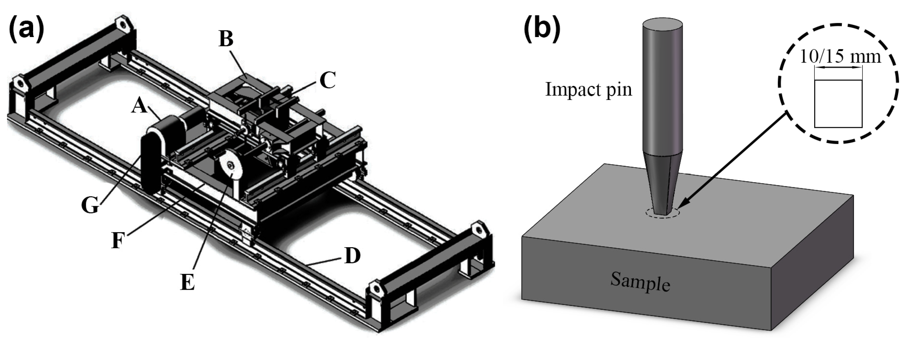
Table 1 was used as the test steel. Its chemical composition was determined by an optical emission spectrometer. The test steel was first subjected to solution treatment to obtain single-phase austenite followed by heating to 1050 °C, holding for 1 h, and then water-cooling. A surface impact hardening equipment was employed to pre-harden the test steel under different parameters, including sample temperature, impact pin size, and impact times on a single point. The impact pines were made of GCr15 with the chemical compositions (wt. %) of 0.99C, 0.22Si, 0.37Mn, 1.50Cr, 0.01P, and 0.01S. The heat treatment was based on quenching followed by low-temperature tempering. During the impact hardening process, the impact pin moved at a steady rate with the sample. The impact energy was set to 50 J, and the sample was cooled in air after impact hardening. A schematic diagram of surface impact hardening equipment is provided in
Figure 1, with the impact pin shape and size shown in the upper right corner of the
Figure 1b. The sample number after surface impact hardening was recorded as sample temperature (°C)—impact pin size (mm)—impact times on a single point. The numbers were estimated to be 100-10-6, 200-10-6, 200-15-6, 300-10-3, 300-10-9, and 300-15-6, respectively.
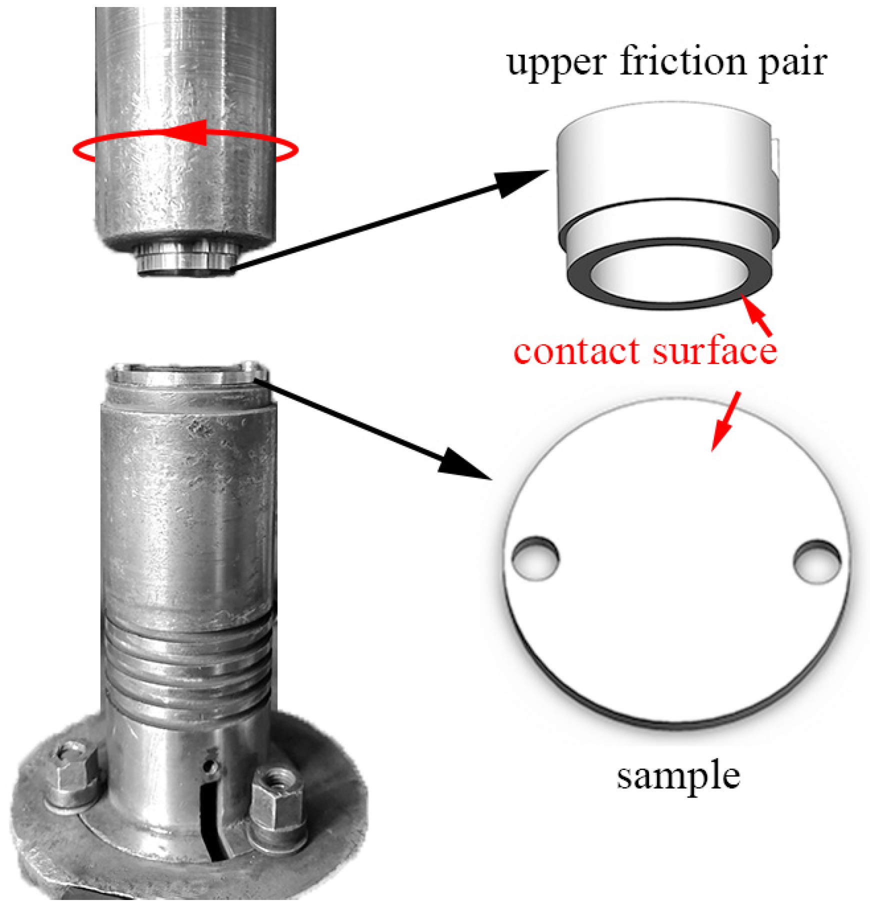
The wear resistance under dry sliding friction conditions of high manganese steel was tested on an MMU-5G (Yihua, Jinan, China) wear testing machine. GCr15 steel was selected as the upper friction pair, with a hardness value of about 780 HV after quenching followed by low-temperature tempering. The upper and lower friction pairs are shown in
Figure 2. The working surface of the upper friction pair is a ring with an inner diameter of 20 mm and an outer diameter of 26 mm. The lower friction pair (test sample) is circular with specifications of ϕ43 mm × 3 mm. The wear test load was 1000 N, and the upper friction pair speed was 200 r/min. Each sample was subjected to pre-wear for 5 min before wear testing to yield a better contact effect and reduce the influence of the sample surface condition on the test results. Afterward, the accumulated weight loss was recorded every 30 min, and the maximum wear time was 120 min. The test process was based on circulating air for cooling. Three samples were involved for each test condition. HVS1000A-XYT (Huayin, Yantai, China) micro-Vickers hardness tester was used to determine the surface and cross-sectional hardness after hardening and wear tests, and test parameters were based on the load of 200 gf and retention time of 10 s. The top-surface hardness of the sample is tested at 9 points, and the cross-section hardness is tested at 5 positions at the same depth. The average hardness value with standard deviation was calculated. The cross-section hardness before and after wear test was measured at the distances of 0.15, 0.30, 0.45, and 0.60 mm from the worn surface, and the following points had intervals of 3 mm.
An Axiover 200MAT (Göttingen, Germany) optical microscope was utilized for surface and cross-sectional microstructure observations of the samples after hardening and wear testing. A SmartLab 9kW (Tokyo, Japan) X-ray diffractometer was employed to evaluate the dislocation densities of the hardened sample surfaces under the continuous scanning method. The testing range was set from 40° to 130° with a step size of 0.01° and a scanning speed of 1°/min. The X-ray diffraction with Kα radiation from a Co target and characteristic wavelength λ of 1.7890 Å was used for crystal structure under an operating voltage of 40 kV and current of 135 mA. A JEM-2010 (JEOL, Tokyo, Japan) transmission electron microscope (TEM) was used for microstructural observations of the hardened sample surfaces under an electron acceleration voltage of 200 kV. The samples were prepared by cutting a 300 μm thick sheet with a wire-cut electrical discharge machine (WEDM, HF320Z, Huafang, Hangzhou, China) followed by grinding the sheet to a thickness of 30 μm on both sides according to an abrasive paper roughness from coarse to fine before using a TenuPol-5 (Struers, Copenhagen, Denmark) twin-jet polisher to prepare a thin area. The electrolyte consisted of 10% by volume perchloric acid and 90% alcohol (C2H5OH). The surface microstructures of the hardened samples were characterized by electron backscattered diffraction (EBSD) technique under an EDAX (Hitachi, Tokyo, Japan) high-resolution probe equipped with a SU-5000 (Hitachi, Tokyo, Japan) field emission scanning electron microscope (FESEM) at the operating voltage of 30 kV. The samples were prepared by cutting out square samples with thicknesses less than 5 mm by WEDM followed by grinding off the surface layer of oxide according to an abrasive paper roughness from coarse to fine before polishing and subjection of IM4000 (Hitachi, Tokyo, Japan) ion milling system (IMS) for 15 min with an angle of 75°. The micro morphologies of the worn surfaces were viewed by a SU-5000 FESEM. A Contour GT (Bruker, Billerica, MA, USA) optical interferometer is used to test the worn volume of samples after wear test.
3. Results
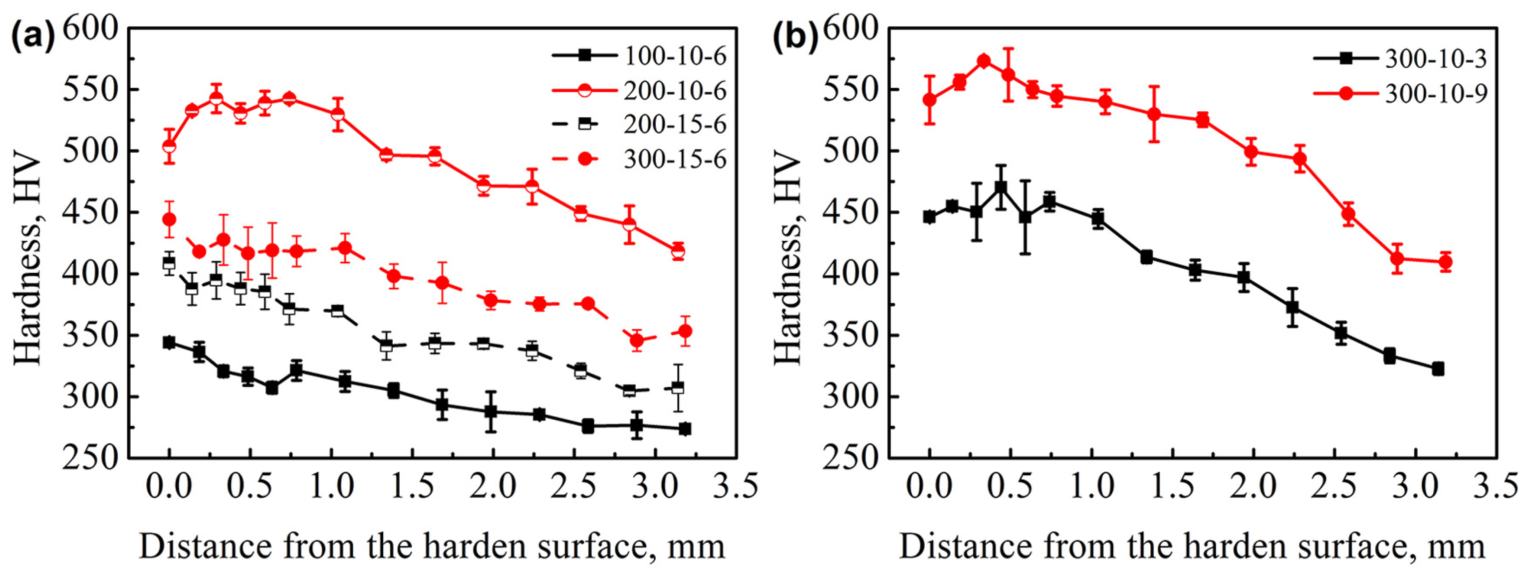
The cross-sectional hardness distribution of 120Mn13 steel after surface impact hardening is illustrated in
Figure 3. The cross-sectional hardness presented a hardness gradient, where hardness varied with the distance from the top surface. The hardness values of 100-10-6, 200-15-6, and 300-15-6 samples decreased continuously as a function of distance from the top surface. By comparison, the other samples obtained higher overall hardness values, but with surface hardness lower than that of the subsurface. Additionally, the cross-section hardness values of the samples at the same depth from the top surface increased with increasing the sample temperature and the impact times on a single-point, and decreasing the impact pin size.
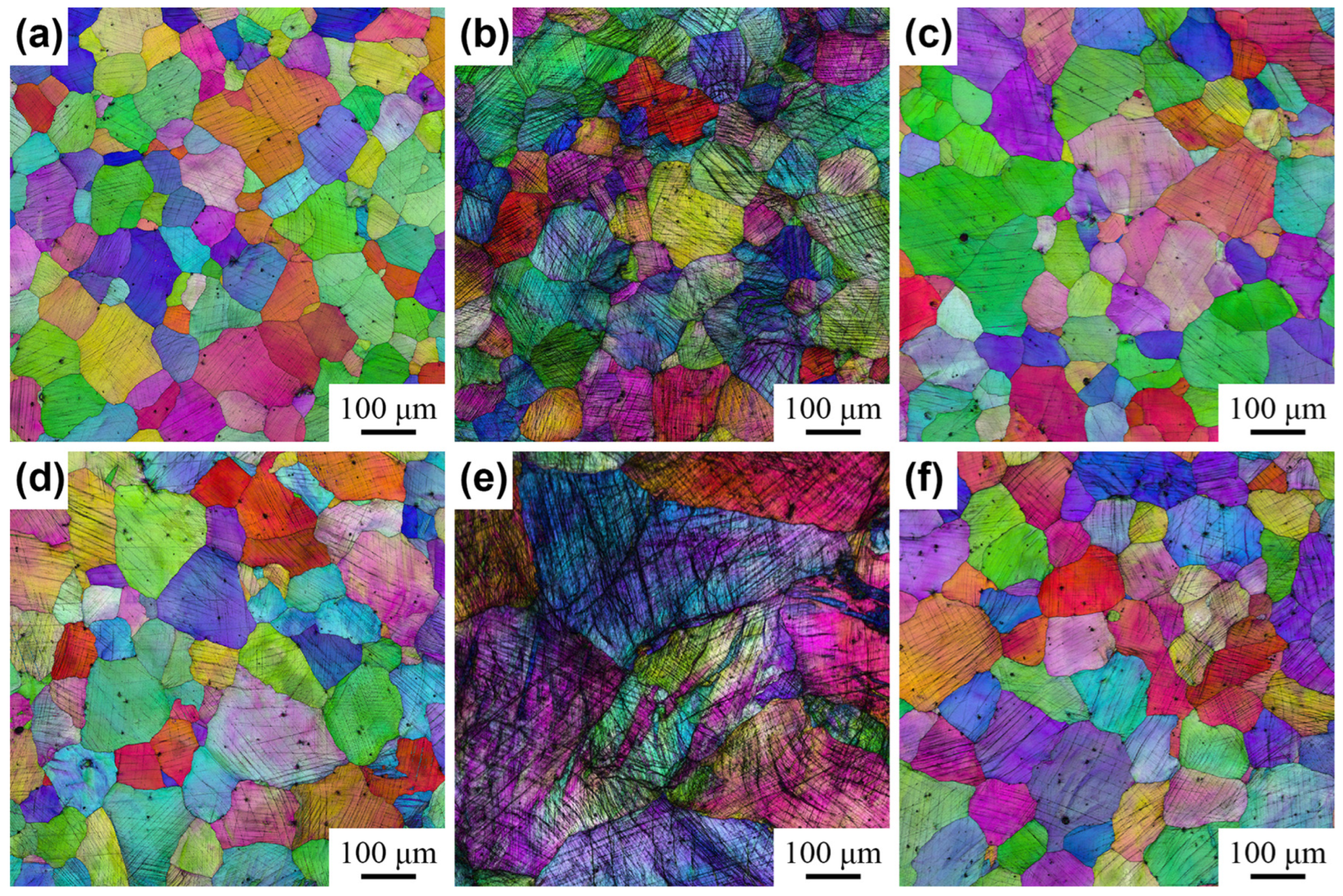
The EBSD images of 120Mn13 steel surface after impact hardening are presented in
Figure 4. When the test steel was impacted, numerous deformation bands were generated on the surface due to plastic deformation. Overall, the 200-10-6 and 300-10-9 samples displayed more obvious deformation bands. The average quantified spacings of the deformation bands are listed in
Table 2. By contrast, the average spacings of the deformation bands decreased as the sample temperature (
Figure 4a–c,f) and the impact times on a single-point (
Figure 4d,e) increased, and the impact pin size (
Figure 4b,c) decreased. In addition, since the sample of the test steel was randomly selected location and cast, varying grain sizes existed in
Figure 4e.
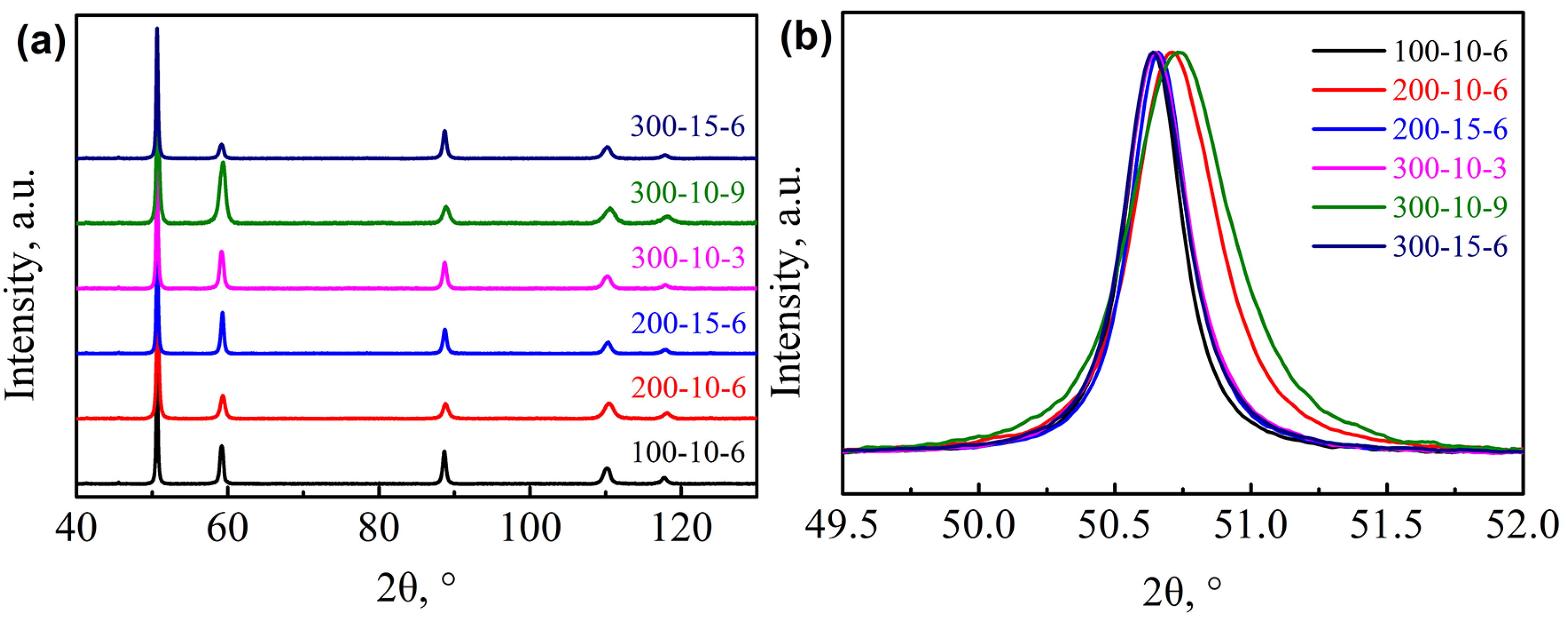
The X-ray diffraction (XRD) patterns of 120Mn13 steel surfaces after surface impact hardening are provided in
Figure 5. All test steels showed single-phase austenitic. The lowest phase content that can be detected by XRD was generally around 5%, indicating no martensitic phase transformation and carbide generation. In addition, the peak positions of 200-10-6 and 300-10-9 samples significantly shifted toward higher 2θ angles, while peak widths became wider than those of other samples (
Figure 5b). Thus, both samples underwent severe plastic deformation at the surface to introduce residual stresses [
17]. The relationship between the crystal plane spacing, diffraction angle, and X-ray wavelength can be expressed by the Bragg equation.
where
d represents the crystal plane spacing,
θ is the diffraction angle between the incident X-rays and the corresponding crystal plane,
λ refers to the wavelength of the incident X-rays, and
n is the number of diffraction levels. Under constant wavelength of incident X-rays, an increase in the diffraction angle would imply a decrease in the crystal plane spacing, meaning enhanced residual compressive stress to induce crystal shrinkage [
24].
Meanwhile, the XRD data suggested dislocation density in the microstructures of different impact parameters, thereby being analyzed semi-quantitatively. According to the dislocation density model [
25], the dislocation density can be expressed in terms of microscopic strain.
where
ρ is the dislocation density,
K represents a constant taken as
K = 12
A (
A = π/2).
ε refers to the microscopic strain,
F is a constant taken as
F = 1, and
b is the Burgers vector of Fe. The calculated dislocation densities on test steel surfaces after hardening are summarized in
Table 3. The dislocation densities of different impact samples increased with increasing the sample temperature and the impact times on a single-point, and decreasing the impact pin size. In addition, the dislocation density variation was consistent with the number of deformation bands in the microstructure. Among samples, the dislocation density of 300-10-9 sample reached as high as 7.04 × 10
15 m
−2. Moreover, the dislocation density of test steel did not yet reach saturation under the used impact hardening treatment.
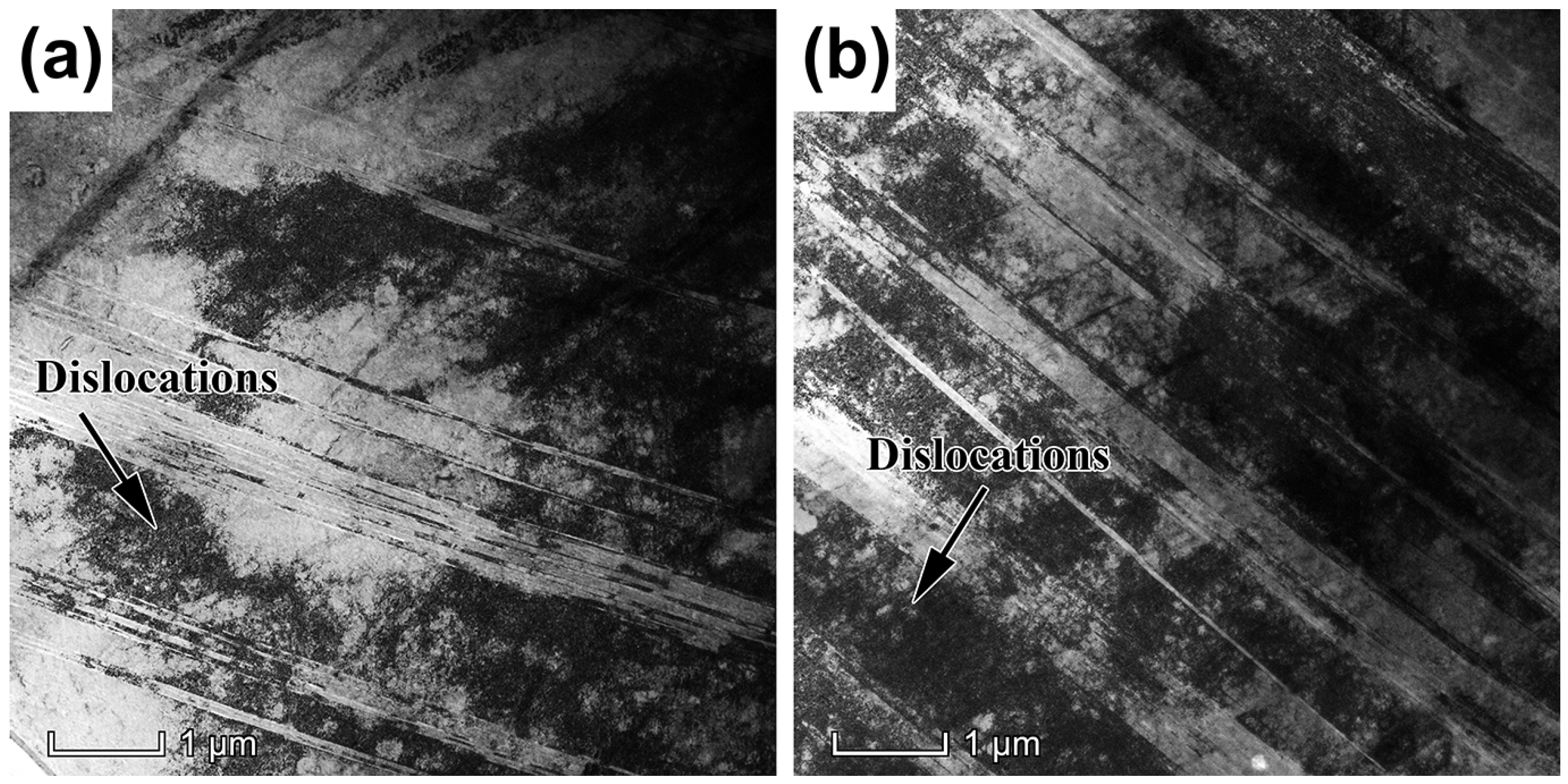
The TEM images of two impact samples 300-10-3 and 300-10-9 are given in
Figure 6. After the impact hardening treatment, large numbers of dislocations and twins formed on the top surface, while twins of the test steel were crossed. The 300-10-3 sample showed a large twin spacing and low twin density, while 300-10-9 sample displayed a small twin spacing and high twin density. The change in the twin density of the test steel microstructure after impact hardening treatment was consistent with the number of deformation bands and dislocation density. Note that the deformation bands in
Figure 4 should be twins.
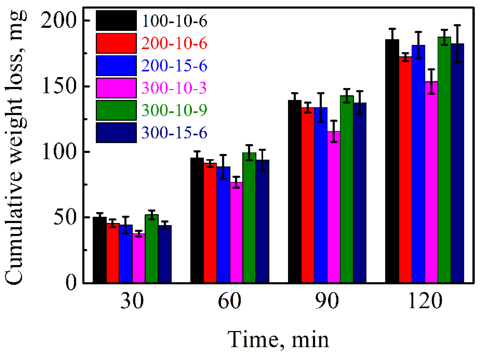
The trend of cumulative weight loss with wear time for 120Mn13 steel under wear load is presented in
Figure 7. The cumulative weight loss of test steel under different impact parameters increased with wear time in an almost linear trend. As the sample temperature increased from 100 °C to 200 °C, the cumulative weight loss showed a certain degree of reduction in 100-10-6 and 200-10-6. As sample temperature incremented from 200 °C to 300 °C, no significant change was noticed in 200-15-6 and 300-15-6. As impact pin size rose from 10 × 10 mm
2 to 15 × 15 mm
2, some enhancement was noticed in 200-10-6 and 200-15-6. As impact times on a single point increased from 3 to 9, a considerable raise was noticed in 300-10-3 and 300-10-9. Overall, the 300-10-3 sample exhibited the best wear resistance.
Table 4 shows the worn volume and the wear factor. Among them, the relationship between the worn volume and the wear factor can be expressed by the following equation [
26].
where
K is the wear factor,
V is the worn volume,
L is the normal applied load, and
S is the sliding distance. The results show that the wear factor is as low as 1.05 × 10
−14 m
2·N
−1 for the sample 300-10-3, which is much lower than that of laser surface melted samples of DIN X42Cr13 reported by Colaço et al. [
26].
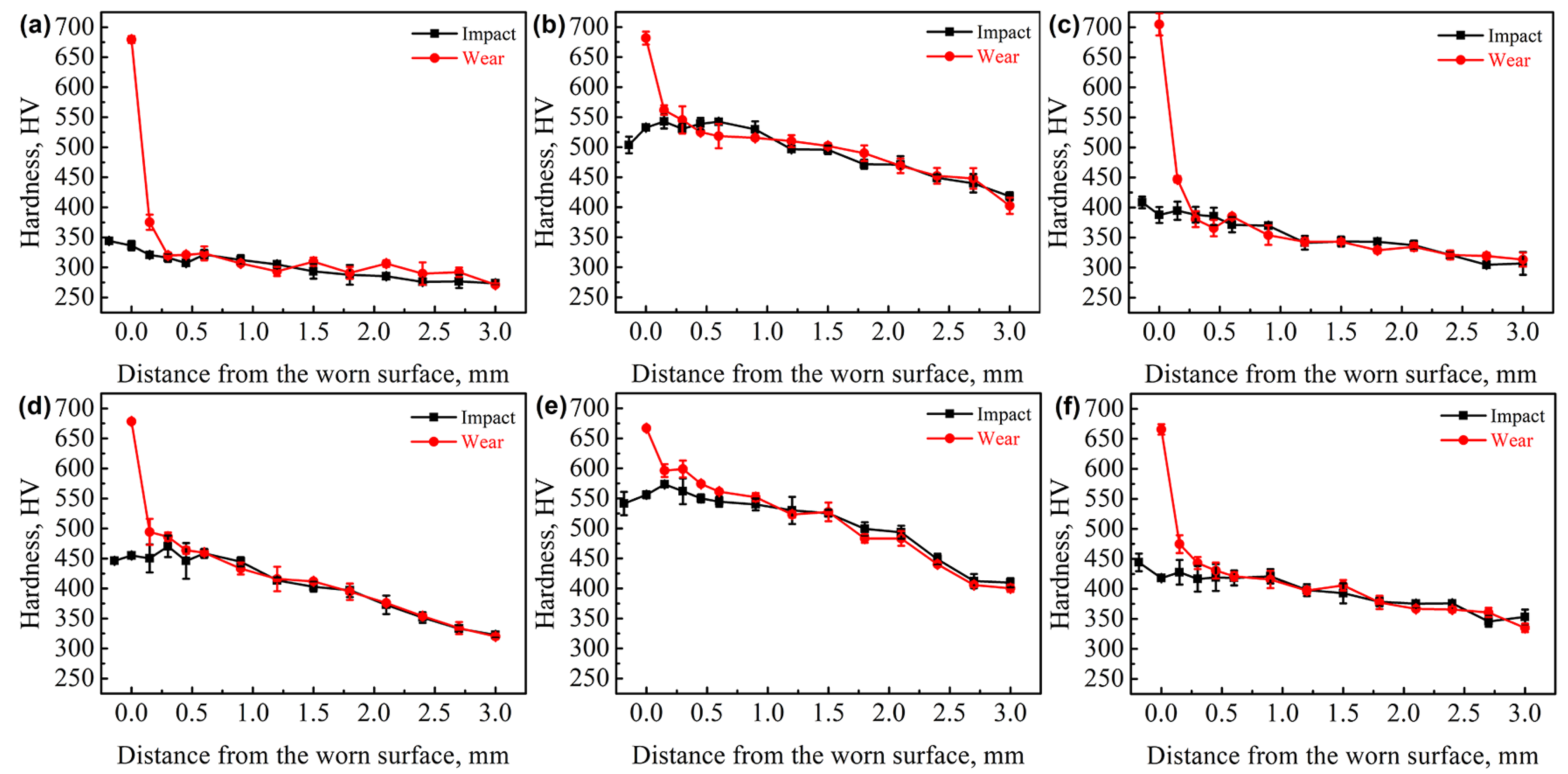
The relationship between hardness of the sample cross-section and distance from the worn surface of 120Mn13 steel after hardening and wear testing of 1000 N for 120 min is depicted in
Figure 8. The hardness decreased with distance from the worn surface. By comparison with the distribution of hardness after impact, the samples produced different degrees of hardened layers under wear testing, with depths estimated to about 0.3–0.45 mm, and surface hardness values of different samples reached about 680 HV. In addition, the lower subsurface hardness of the sample after impact resulted in a more pronounced hardness gradient cross-section after wear testing.
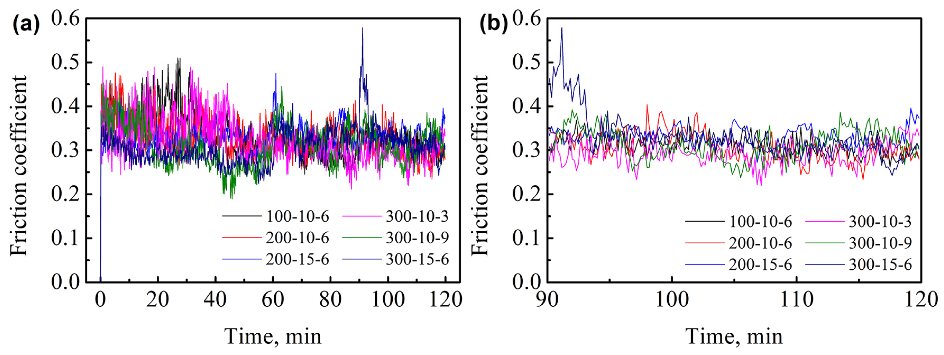
The variations in the coefficient of friction of different samples during the wear test are displayed in
Figure 9. The friction coefficient distributions at the beginning of wear for different samples ranged within 0.25–0.5. After some time, a stable trend was noticed at about 0.3. At the late stage of the wear testing under different impact parameters, the friction coefficients tended to stabilize to the same level.
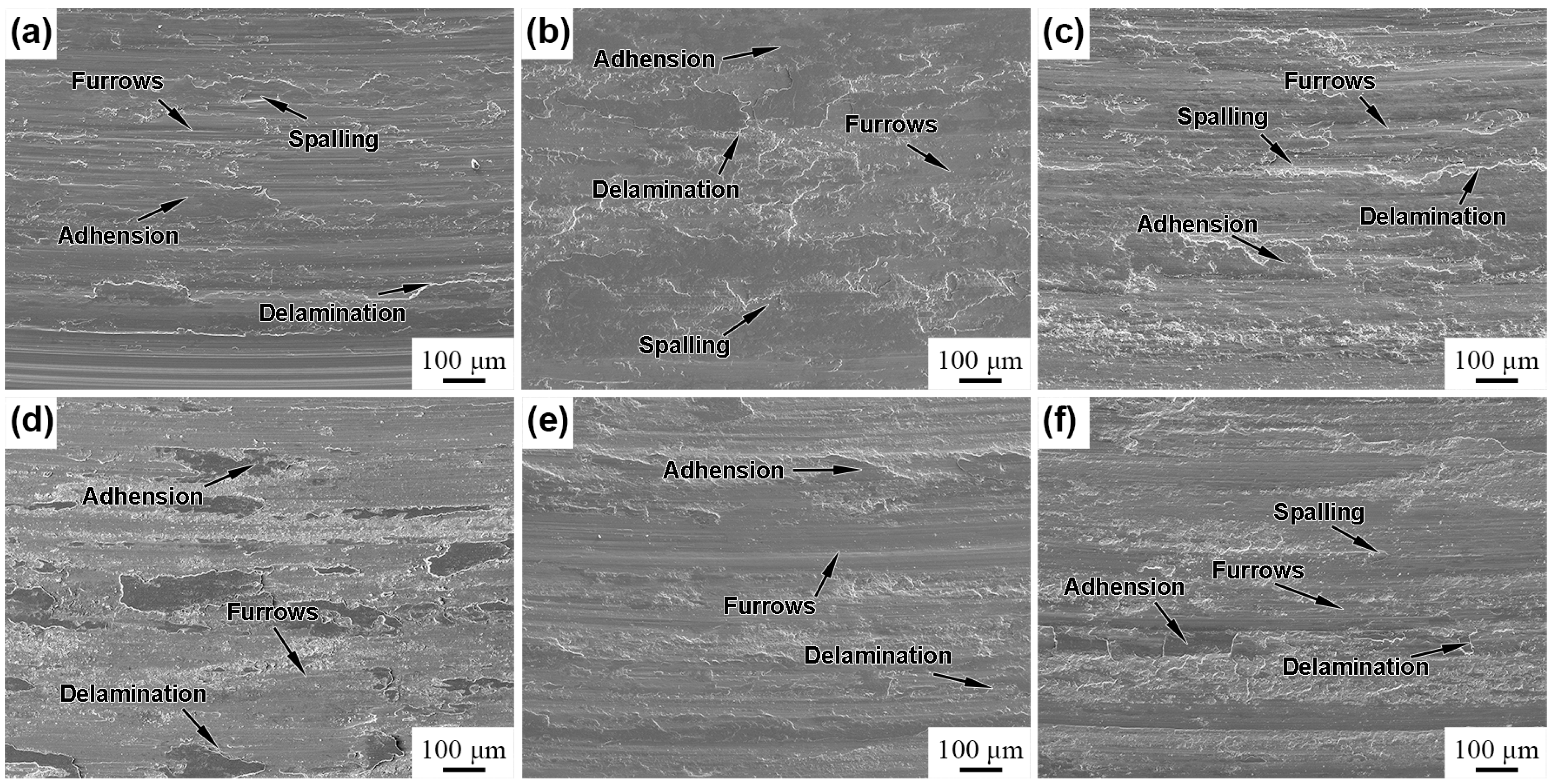
The SEM images of 120Mn13 steel at the same locations after wear testing are presented in
Figure 10. The sample worn surface produced large numbers of furrows, abrasive chips, adhesion, spalling, and delamination, indicating adhesive wear and abrasive wear mechanism. As the sample temperature changed from 100 °C to 200 °C, the hardness of test steel increased, the furrows in worn surface morphologies became inconspicuous, and the wear mechanism changed from abrasive wear to adhesive wear (
Figure 10a,b). As the sample temperature changed from 200 °C to 300 °C, the hardness increased slightly, variance in worn surface morphologies was not obvious, and wear mechanisms were all based on adhesive wear (
Figure 10c,f). As impact pin size rose and impact pin size changed from 10 × 10 mm
2 to 15 × 15 mm
2, the hardness declined, furrows of the worn surface morphologies became obvious, and the wear mechanism changed from mainly adhesive wear to mainly abrasive wear (
Figure 10b,c). The rise in the number of single-point impacts during the impact hardening process at impact times on a single-point from 3 to 9 resulted in declined hardness of the sample, formation of large numbers of furrows on the worn surface, and variation in wear mechanism from adhesive wear to abrasive wear (
Figure 10d,e). The weight loss of the test steel was mainly attributed to the furrow resulting in furrowing, as well as the shedding of abrasive chips. The worn surface morphologies of the test steel were observed, consistent with the cumulative weight loss variation.
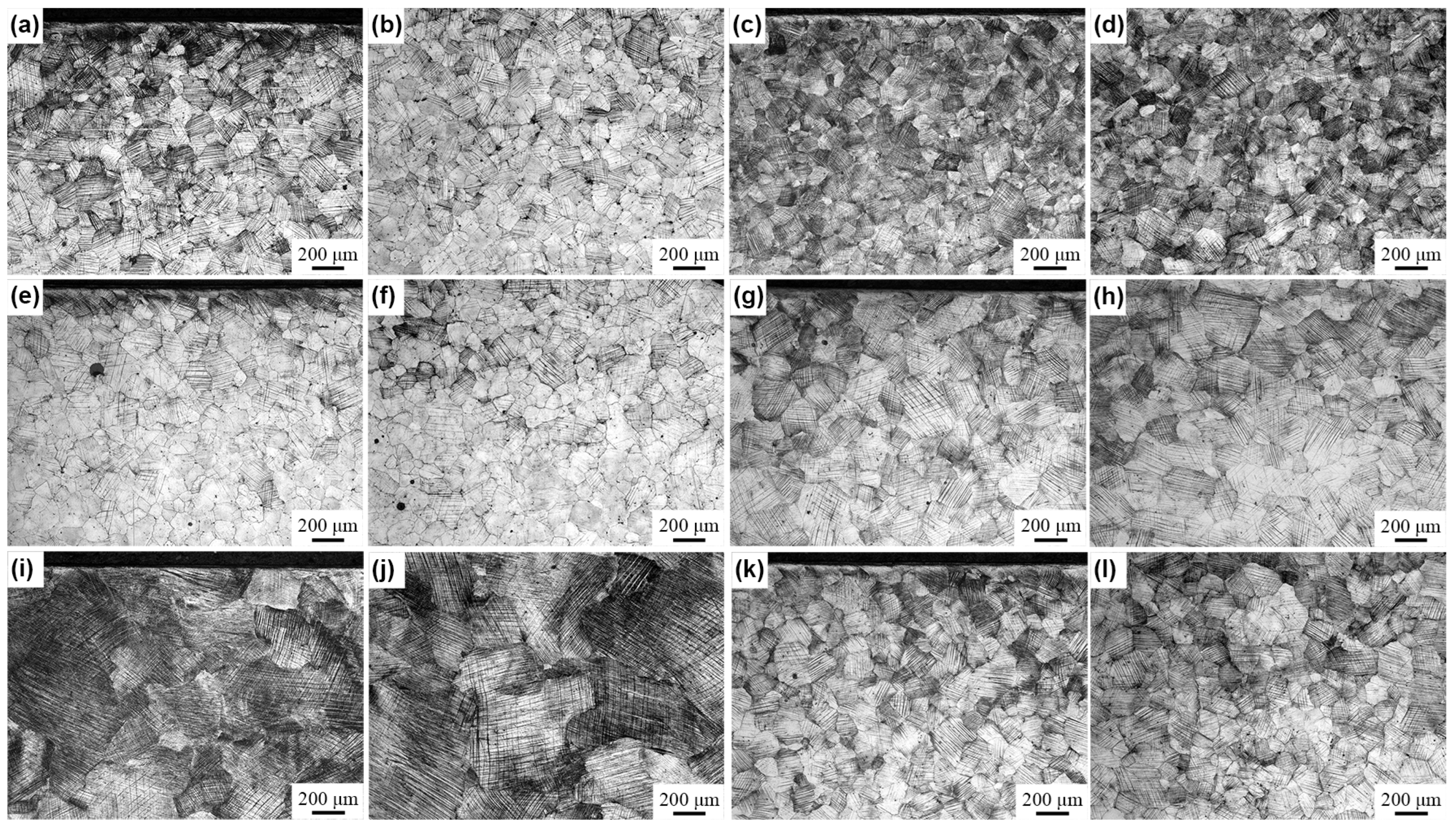
The optical micrographs of the cross-section of 120Mn13 steel after hardening and wear testing at 1000 N for 120 min are provided in
Figure 11. The test steel produced large numbers of deformation bands in the cross-sectional microstructure after the impact hardening treatment. The average spacing of the deformation bands decreased with the increase of the sample temperature and the impact times on a single-point, and the decrease of the impact pin size. The test steel sample subsurface after wear testing showed a more obvious deformation band and deformation microstructure. The deformation band average spacing statistics are summarized in
Table 5. As can be seen, the values of deformation band average spacing on the sample subsurface after wear testing were all around 1 μm, consistent with the hardness results of the sample surface after wear testing.
4. Discussion
The test steel was severely plastically deformed by impact, leading to the formation of large numbers of deformation bands on the top surface and within a certain depth (
Figure 4 and
Figure 11). The variation in impact parameters led to an increased deformation band density, dislocation density, and twin density within the microstructure as a function of the raise in sample temperature and impact times on a single point, as well as a decrease in impact pin size. Hence, the relationship among the hardening effects of different surface impact parameters would be related to the densities of microstructures within the different samples, as well as the hardening effect from weak to strong (100-10-6, 200-15-6, 300-15-6, 300-10-3, 200-10-6, and 300-10-9).
For metallic materials with relatively low stacking fault energy, deformation twins play a key role in the plastic deformation process [
27]. The XRD data revealed that impact hardening did not cause the transformation of austenite to martensite in the test steel. A large number of dislocations and twins were produced on the top surface and within a certain depth, leading to the formation of fine microstructure.
The mechanical responses of materials under dynamic loads, such as explosions and impacts would often be significantly different than under static loads. Under dynamic loading, the mechanical properties of materials may be related to strain rate [
28]. Li et al. [
29] used a split Hopkinson pressure bar for dynamic compression tests and noticed a response time during dynamic deformation, which became shorter as the strain rate increased. They also found that strain and stress increased with the strain rate. Xiong et al. [
30] investigated the dynamic tensile properties of TWIP steels with various compositions at different strain rates. Their data revealed a rise in material tensile strength as a function of strain rate. Zhu et al. [
31] proposed two types of twinning mechanisms called “the self-partial-multiplication twinning mechanism” and “the rebound mechanism”. The nucleation mechanism of deformed twins in test steels under impact loading was the second one due to the instantaneous and huge impact, where high strain rates would promote the twinning mechanism. As the strain rate increased, the twin nucleation rate rose and deformation twins become denser. Shterner et al. [
32] investigated the tensile deformation behavior of a high Mn TWIP steel at different deformation temperatures. They noticed a decrease in the yield strength of the material as deformation temperature, leading to enhanced plastic deformation capacity. For test steel made of surface impact hardening, the raise in sample temperature significantly declined the tensile strength and density of dislocation and twin, while enhancing strain rate and strain under the same impact energy. The competition mechanism may lead to dislocations and denser twins within the test steel. In addition, the reduction in impact pin size and increase in impact times on a single point further incremented the deformation of the material. Thus, the density of the dislocations and twins within the test steel increased continuously with increasing the sample temperature and the impact times on a single-point, and decreasing the impact pin size. In addition, the raise in depth from the impact top surface led to diminished twin density. The much lower plastic strain and strain rate were not conducive to the formation of deformation twins.
Microstructures, such as dislocations and twins formed during plastic deformation of the test steel would influence the hardness [
24]. High-density dislocations could prevent the active slip system and dislocation motion during plastic deformation, leading to the work hardening of the material [
33]. The influence of deformation twin formation in plastic deformation on the work hardening of high manganese steel can be divided into two main aspects. On the one hand, the formation of deformation twins rendered an obstacle to dislocation movement, reducing the mean free path of dislocation movement and significantly increasing the hardness of the sample [
34]. On the other hand, the twins continuously divided the austenite grains, resulting in a dynamic Hall-Page effect, while refinement of the surface grains increased the strength of the material [
35]. The synergistic effect of such microstructures encouraged the high manganese steel to produce impact hardening, thereby increasing hardness. The hardness of the test steel after hardening continuously rose with increasing the sample temperature and the impact times on a single-point, and decreasing the impact pin size (
Figure 3), attributed to the density of dislocations and twins produced after hardening.
As shown in
Figure 3, the top surface hardness of part of the samples was slightly lower than that of the subsurface after surface impact hardening. This can be attributed to the strong impact hardening effect, in which part of the strain energy was converted into heat, leading to temperature rise. Hence, deformed high manganese steel rose recovery under strain-induced conditions, causing the diffusion of atoms at short distances to reduce the density of dislocations and degree of lattice distortion, finally leading to the reduced hardness of the sample’s top surface [
36].
The hardness of the material was influenced by the degree of plastic deformation. In wear testing, the hardness values of the top surface all reached the same level (
Figure 8). Chen et al. [
37] treated samples with the same pounding load and noticed a gradual increase in surface hardness with pounding times, resulting in almost the same value after more than 4 × 10
4 impact times, indicating saturation of work hardening. Moreover, a higher pounding load led to elevated saturation of surface hardness. The deformation degree as a cumulative process made the plastic deformation difficult to rise in the late stage of deformation under a fixed load, while the change in hardness tended to level off. Ye et al. [
38] studied materials treated by ultrasonic striking and recorded no further increase in microhardness in the striking beyond 72,000 times/mm
2 under the same conditions. The significant hardening of the surface greatly hindered further plastic deformation and strengthening, and the internal factor leading to such limited work hardening and hardening depth was related to the accumulation of sessile dislocation [
39]. Therefore, under fixed wear load and after critical time, the plastic deformation degree no longer changed when the test steel reached maximum hardness.
In wear testing, the wear resistance of the material would be closely related to the surface hardness and depth of the hardened layer, and high strength and hardness would often bring better wear resistance [
40]. High manganese steels possess elevated work-hardening capacity and impact toughness, and the special material properties determine the wear behavior that would distinguish them from other wear-resistant materials [
41,
42]. A weak impact hardening effect would induce low surface hardness of test steel, as well as weak resistance to deformation. Here, the sample was greatly deformed under wear load conditions, and the main micro morphologies of the worn surface were characterized by furrows, spalling, and delamination. The weight loss of the sample was induced by the furrow resulting in the furrowing and shedding of abrasive chips (
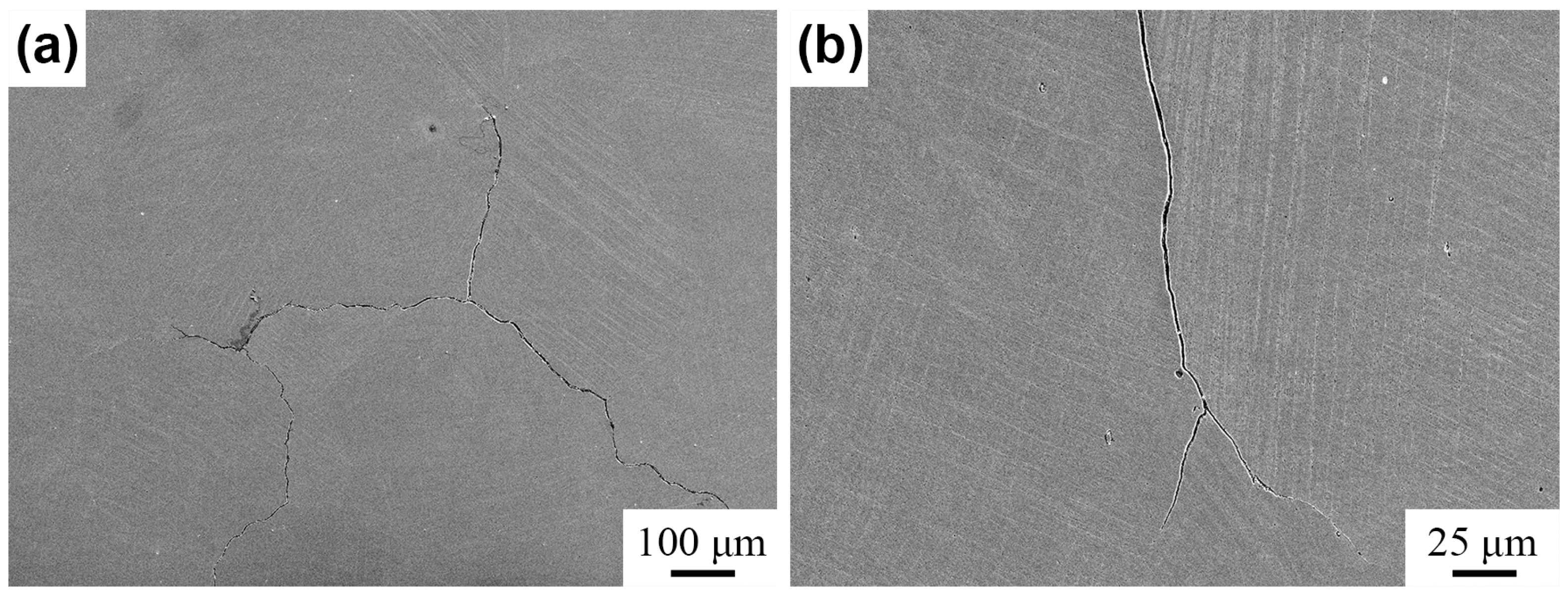
Figure 10). An improvement in impact hardening effect resulted in an increase in the surface hardness. Under the same wear load conditions, the surface of sample can reach saturation hardness in a shorter time. The resistance to deformation was greater, and the furrow of the worn surface became less obvious. The weight loss of the sample was less, and wear resistance improved. However, as the impact hardening effect continued to increase, weight loss rose, wear resistance declined, and worn surface morphologies deteriorated due to two main reasons. On the one hand, the 300-10-9 sample with a larger grain size may bring poorer wear resistance [
43]. On the other hand, the stronger impact hardening effect enhanced the hardness of the sample while inducing surface microcracking along the crystal, resulting in no further increase in wear resistance or even worse (
Figure 12) [
10]. In other words, the impact hardening effect rose again, and the surface hardness of test steel increased but much higher hardness did not result in better wear resistance. Thus, the impact hardening effect should not be too strong. The proper impact can save time and energy, while too much impact would induce a strong impact-hardening effect, leading to large numbers of surface cracks. This produced a large loss of material during the wear process, adversely affecting the wear resistance of high manganese steel.


