1. Introduction
Drop casting is a well-known and widely applied technique for surface modification which can be used for various types of substrates and applied inks. This technique is applicable not only for homogenous solutions but also for colloid systems that can be drop cast for the nanostructuring of surfaces. In this regard, major attention is paid to the processes associated with a so-called coffee-ring effect that results in non-uniform deposition patterns of colloidal particles from droplets upon drying and the practical application of this effect [
1,
2,
3,
4,
5,
6,
7]. It was demonstrated and discussed that both morphology and properties of the formed structures are determined by several parameters such as kinetic factors, substrate properties, and drops composition including properties of the liquid media as well as colloidal particle parameters and their interactions. All of these factors can have significant effects on the architecture of the formed deposits and can be used to manipulate or program them in a certain way for the creation of functional coatings and structures for various applications ranging from optics to biosensorics [
8,
9,
10,
11]. Moreover, a decent contribution to the formed structures can also be made by external stimuli, controlling environmental conditions, application of electromagnetic fields, or acoustic waves. Such active control over the deposit structure allows to create even more sophisticated layers and functional assemblies for smart sensors or functional devices [
12,
13,
14,
15]. In this regard, magnetic colloids are taking a special place as an object of study due to their sensitivity to an external magnetic field [
16,
17,
18,
19]. It was demonstrated for such systems, that the coffee-ring effect can be magnetically manipulated or completely suppressed under appropriate conditions, allowing control of the microstructure of the dried drops.
Despite the fact that this conception is quite obvious and can be practically implemented, it is very complex from the physical point of view of physics. While the process of droplet drying is complex in itself, ferrohydrodynamics and energy transfer processes within magnetic hydrosols under the influence of an external field add a number of additional factors that complicate the description of the whole process [
20,
21,
22]. Moreover, the main attention in magnetic fluids and deposit manipulation is paid to the application of a magnetic field, while the electrophoretic behavior of the droplets is less known. There are several articles devoted to the electric manipulation of magnetic droplets on a surface or in capillaries [
23,
24,
25] but, to the best of our knowledge, the data about combined magneto- and electrophoretic deposit formation is absent.
In the present work, we study the influence of magnetic and electric fields or their combinations on the deposits formed from magnetic fluids based on water or kerosene. In contrast to organic magnetic fluid, which was stabilized by steric repulsion, single-domain particles in water-based magnetic fluid bared an electric charge on their surface and their stabilization was maintained by double electric layers. Here, we show the difference in the behavior of organic- and water-based magnetic fluid droplets on the solid surface during drying in presence of magnetic and electric fields as well as their combination. For the first time, we demonstrate the influence of combined electrophoresis and magnetophoresis on the morphology of formed deposits. The observed results and the corresponding theoretical basis are discussed.
2. Materials and Methods
Water-based magnetic fluid (Sample No.1): The material was synthesized by the modified co-precipitation protocol described earlier [
26]. Briefly, 2.5 g of iron chloride (II) tetrahydrate (Sigma Aldrich, St. Louis, MO, USA) and 5 g of iron chloride (III) hexahydrate (Sigma Aldrich, St. Louis, MO, USA) were dissolved in deionized water and 11 mL of ammonia (Sigma Aldrich, St. Louis, MO, USA) was added under constant stirring. The formed iron oxide was magnetically separated, washed until neutral pH with deionized water, and ultrasonically dispersed in 100 mL of deionized water for two hours. The resulting stable hydrosol consisted of 10 ± 3 nm magnetite nanoparticles with 0.5% wt. of the solid fraction.
Kerosene-based magnetic fluid (Sample No.2): The material was synthesized as follows: 4.32 g of iron chloride (III) hexahydrate, 1.6 g of iron chloride (II) tetrahydrate and 19 g of oleic acid were soluted in 160 mL of ethanol/water/toluene (Sigma Aldrich, St. Louis, MO, USA) mixture with a fraction 1:1:2 under reflux. A total of 2.4 g of sodium hydroxide (Sigma Aldrich, St. Louis, MO, USA) dissolved in 5 mL of ethanol/water/toluene mixture was added quickly. Reflux was continued for a further 2 h. Once cooled, an excess of ethanol was added and the precipitate was collected by centrifugation at 4000× g. The precipitate was washed 4 times with ethanol and dispersed in 100 mL of kerosene (Arikon, Moscow, Russia) with 0.1 mL of oleic acid (Sigma Aldrich, St. Louis, MO, USA). The sol consisted of 11 ± 3 nm magnetite nanoparticles and 0.5% wt. of the solid fraction.
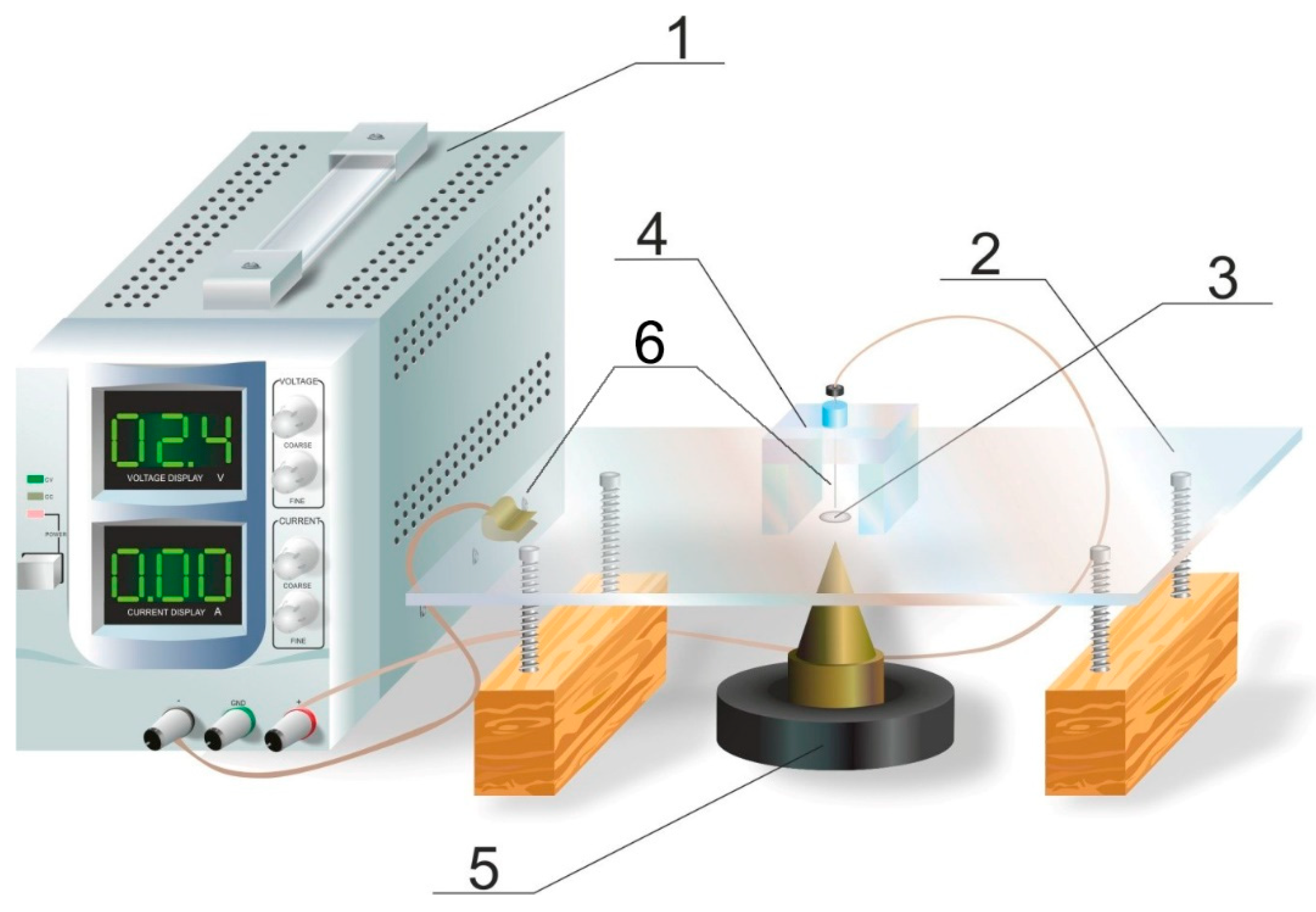
Droplets preparation and drying: The schematic representation of the experimental setup is represented in
Figure 1. A total of 100 μL of the sample were applied on the horizontally placed glass plates preliminarily treated with a 1:1 mixture of acetone and ethyl alcohol to form a drop with a diameter of 8 mm. Droplets were dried in a closed space to prevent air flow at room temperature. To study the processes of rings formation in the presence of magnetic fields, the glass with a drop was placed over a conical ferromagnetic core and the fields were created by an annular permanent magnet or with a magnetizing coil, the tip of the core was directly under the glass substrate opposite the center of the flat drop (
Figure 1). The used magnetizing system created an inhomogeneous magnetic field symmetrical to the center of the drop. The maximum achievable value of its intensity in the geometric center of the drop base was 9883 A/m, and the value of its average change per unit length
equaled 4.5 × 10
6 A/m
2. It should be that in strong magnetic fields, deformation of the free surface of the magnetic fluid can occur; however, under the conditions of the experiments presented here, this was not visually observed.
To study the influence of an electric field on the structure of the formed deposits, ITO glass plates (Research and Training Center of Photovoltaics and Nanotechnology, Stavropol, Russia) with a transparent conductive coating were used (
Figure 1). The homemade brass needle electrode (6) was lowered into the drop (3) located on the conductive substrate (2), the voltage between which and the conductive substrate was created with a stabilized direct current source MATRIX MPS–3003L-1 type (Martix Technology Inc., Shenzhen, China) (1). The distance between the electrode and the evaporating drop was regulated using a micrometric feed. In the case of studying the formation of a deposit under the simultaneous action of electric and magnetic fields, the installation was supplemented with a magnetizing system (5).
Sediments analysis: Sediment formation was observed both visually and using an optical microscope (BIOLAM LOMO, Saint-Petersburg, Russia) equipped with a video camera (Samsung, Seoul, Republic of Korea). The analysis of the architecture of the formed sediments was carried out based on the obtained images. Profiles and relative thicknesses of the sediments of dried drops were studied in a manner described earlier by analyzing digital images of the sediments [
27].
3. Results
To investigate the process of deposits formation from kerosene- or water-based magnetic fluids, these were applied on glass substrates and dried in an isolated environment. When the drops of both samples were dried on a solid substrate, ring structures were formed on the perimeter of the drops (
Figure 2a,b) similar to those studied earlier [
28,
29,
30,
31,
32,
33]. Profile and relative thicknesses of the drops were investigated by photometry and are presented in
Figure 2c,d. The profile of the drops had some degree of variation due to differences in their chemical composition; at the same time, the mass fraction of solids in both liquids was the same valued at 0.5% wt.
The application of an external magnetic field during the process of drying significantly altered the profiles of formed deposits in a similar way, as was reported earlier [
27]. Under the influence of a nonhomogeneous magnetic field with a cone inductor, the drops of both water- and kerosene-based fluids formed a round spot in the center while the formation of a ring on the perimeter of the drop was not observed (
Figure 3a,b).
Profiles of the drops are shown in
Figure 3a,b. Despite the outward similarity in the shape of the sediments of both samples, their structure differed noticeably. The observed effect can be attributed to the peculiarities of the mechanisms in sediments formation during drops evaporation for used fluids. The origins of these peculiarities should be in the physical properties of these liquids as both of them contained similar magnetic components.
The regulation of sedimentation was also possible using an electric field. To do this, drops were placed on an ITO glass and a needle electrode was placed in the center of the drop, and drops were dried under the influence of a constant electric potential. Experiments showed that the structures of the formed deposits were dependent on the polarity of the electrodes, as can be seen in
Figure 4a. However, such an effect was observed only for sample No. 1, while sample No. 2 did not respond in the range of the applied electric potentials.
As can be seen, the polarity of the substrate and the needle electrode had a significant influence on the appearance of the dried drop. When a positive potential was applied to the substrate, the thickness of the central part of the deposit decreased compared to the deposit formed without field, while a thin ring remained around the droplet perimeter (
Figure 4a upper line). In this case, a dense volumetric deposit was formed directly on the needle electrode. When the polarity of the electrodes was changed the observed effect was contrary and the deposit was evenly distributed over the area of the dried drop. In the latter case, the overall thickness was also much greater (
Figure 4a bottom line). This observation was also proved with photometry profiles shown in
Figure 4b,c, which were measured for samples at a potential difference between the electrodes U = 5 V. It can be seen that the relative density of the formed deposit was almost linearly dependent on the applied potential of the needle electrode (
Figure 4d).
As the next step, the process of the formation of a deposit in sample No. 1 under the simultaneous action of magnetic and electric fields was investigated. It turned out that application of an electric field on an evaporating droplet in a non-uniform magnetic field led to a change in the architecture of the formed precipitate (
Figure 5). When a negative potential was applied to the substrate and a non-uniform magnetic field was applied under the center of a drop, the appearance of the dried drop was dependent on the strength of the applied potential (
Figure 5a). As it was observed, electric potential had a non-linear influence on the appearance of the formed residue. In the presence of the electric field of 1 V, the diameter of the central spot became almost twice larger and expanded from 3 to 6 mm, while with the further elevation of the potential, other changes occur in the architecture of the deposit (
Figure 5b). So, when the voltage on the electrodes exceeded a value of about 3 V, the outer edge of the central spot brightened, and a thin rim appeared around the perimeter of the entire drop, the width of which increased with a further increase in voltage.
Figure 5c shows the dependence of the width of this annular deposit on the voltage at the electrodes.
4. Discussion
Features of flow formation in a drying drop and the processes of particles deposition during the drying of flat colloid droplets located on solid substrates were previously described in several works [
2,
28,
34,
35,
36,
37]. They indicate the importance of the behavior of a contact line, which is a three-phase boundary solution/substrate/air, for describing the hydrodynamics of processes inside a drop. Two main scenarios for the contact line movement line can be realized depending on the wettability of the substrate and the size of the drop. In the first one, the contact line can stand still or move very slowly during the drying of the drop, while the contact angle between the solution and the substrate decreases. In the second scenario, the contact angle does not change, while the contact line moves. The first scenario is realized in the case of good wettability of the substrate by the solution when capillary forces are relatively weak. In this case, the slow movement is facilitated by the rapidity of evaporation. The second scenario takes place when the substrate is weakly wetted by the solution in the case of relatively high capillary forces, as a result of which the substrate does not hold the contact line. According to Ref. [
28], when the contact line is held by the substrate (pinning), radial flows of a compensatory nature arise in the drop.
A theoretical consideration of the diffusion evaporation of a drop was carried out in papers by Hu et al. [
34,
35]. According to their results, the approximation expression for the evaporation flux density has the form:
where
r,
θ and
R, are the radial coordinate, contact angle, and wetted radius, respectively. The expressions of
J0() and
λ() are given as follows [
34]:
where
ns is the concentration of solvent on the surface of the drop. The performed calculations showed that the evaporation flux density increases with the approach from the drop dome to the contact line in the case of a contact angle smaller than the right angle. In the case of pinning of the contact line by the substrate, maintaining the constancy of the contact area during the removal of liquid due to evaporation is carried out by the supply of the solution to the periphery, i.e., the occurrence of radial compensation flows.
Computer simulation of compensatory hydrodynamic flows in a drop was carried out in Ref. [
37]. It was shown that in the case of pinning, the flows are indeed directed from the top to the peripheral regions. The process of sediment formation during the drying of flat drops is directly related to the arising flows, which move the particles dissolved in the drop from the center to the periphery, forming a characteristic annular thickening [
32,
38]. This was clearly seen for the drops of magnetic colloids based on water and kerosene used in this work due to their good wettability of glass, as is seen in
Figure 2.
In Ref. [
39], the formation of the architecture of a deposit is considered as a process of self-assembly of particles from a disordered state to an ordered one. This process occurs due to the evaporation of the dispersion medium and a decrease in the volume of the drop. As a result, the boundaries of the droplet, on which capillary forces act, are displaced and set the medium in motion in the volume of the droplet. Thus, one of the determining factors in the development of this process is the ratio of capillary and volume forces acting on the drop. An important role is also played by the forces of interparticle interaction as well as the adsorption of particles and the solution as a whole to the substrate. An additional influence on the process of self-assembly of colloidal particles can be exerted by external fields, the effect of which makes it possible to control the process of self-assembly.
The processes of particle self-assembly in an evaporating drop can be described using the methods of dissipative dynamics [
37,
39]. The motion of a colloidal particle is described by Equation (3):
where
—the sum of conservative forces acting on the particle,
—is the dissipative force that describes the interaction of particles with a dispersion medium—viscous friction and entrainment of a particle by a liquid phase flow,
—is the random Brownian force due to thermal motion.
As mentioned above, an important role in the process of self-assembly of colloidal particles is played by the forces of their interaction. According to DLFO theory, the total energy of interaction of two colloidal particles consists of the energy of attraction and repulsion and can be represented in the case of electrostatic stabilization of the colloid as described by Equation (4):
where,
B—is a factor that depends on the values of the electric potentials of the DEL, the properties of the medium and temperature,
χ—is the thickness of the diffusion layer,
r—is the distance between the particles,
A—is the constant of molecular forces of attraction. The first term in this expression characterizes the repulsion energy of particles, the second corresponds to the energy of their attraction.
According to Equation (4), at a certain distance between the particles, there is a repulsion maximum; in addition, at smaller distances, the repulsive energy decreases and turns into attractive energy, which causes sticking of those particles that have overcome the repulsion barrier. It should be noted that for the magnetic colloids studied in this work, the magnetic dipole interaction of particles also plays a significant role, to take into account which, in Expression (4), it is necessary to add a term characterizing it. It is defined by Equation (5):
where
α1 and
α2—are the angles between the directions of the magnetic moments of the particles
m1 and
m2 and
r is the vector connecting them.
At the same time, a significant difference between the studied samples is the method of their stabilization. Thus, in contrast to the electrostatically stabilized sample No. 1, the stability of sample No. 2 is maintained by the repulsive action of solvate shells formed on the surface of colloidal particles by long-chain surfactant molecules. The particle repulsion energy upon such stabilization can be written by Equation (6):
where
ξ—is the surface concentration of oleic acid molecules adsorbed on the particle surface,
l—is the length of the oleic acid molecule [
40].
In the case of external fields, the resulting additional forces must be taken into account. Thus, for the magnetic colloids studied in this work, the self-assembly processes can be significantly affected by the action of magnetic fields. Indeed, the action of a magnetic field leads to a change in the direction of colloidal particles’ moments and a change in their magnetic dipole interaction energy according to Equation (5). Moreover, in inhomogeneous magnetic fields, magnetic colloidal particles are affected by the force that can be described by Equation (7):
where
pm—is the magnetic moment of the particle, and
B—is the magnetic field induction. This force leads to the displacement of single-domain colloidal particles into the region of a stronger field and concentrates them near the magnet pole piece.
The effect of an electric field is also leading to the appearance of effecting forces that should be taken into consideration. They can be caused both by the presence of a charge on the surface of colloidal particles for water-based system No. 1 and by the electric moment induced by the field in the particle. The corresponding electric forces can be written by Equation (8):
where
q—is the particle charge,
pe—its dipole moment, and
E—electric field strength. In addition, the appearance of an electric field may induce electric moments in colloidal particles and increase the degree of their interaction, which should also be reflected in Equation (4).
As can be seen, the process of precipitate formation during the evaporation of the studied colloids is rather complicated due to the influence of the multiple factors mentioned above. At the same time, the application of electromagnetic fields leads to additional problems and makes the creation of a calculative theoretical model an extremely difficult task. This problem will be addressed in our upcoming works.
Considering the number of forces that affects the nanoparticles in the solution, the process of precipitate formation from evaporating droplets can be rather complicated. When it comes to the behavior of sediments of dried drops of both samples in a non-uniform magnetic field (
Figure 3) it is obvious that the main driving force of this process is the additional effect of magnetic force (Equation (7)) which initiates the occurrence of magnetophoresis. This process occurs in magnetic colloids in nonuniform magnetic fields and has been intensively studied in many works [
41,
42,
43]. According to the configuration of the applied magnetic field created with the help of the conical pole of the magnet, the magnetic colloidal particles tend to move to the area of the stronger field, i.e., to the center of the drop. Experimental results clearly showed the disappearance of the annular deposit along with the drop perimeter, which was observed in the absence of a field, and the formation of a dark disk in the center of the drop. In this case, the magnetic forces prevailed over other forces involved in the formation of the sediment. Since both magnetic fluids contained single-domain superparamagnetic nanoparticles, they showed a similar tendency for deposit formation in a non-uniform magnetic field. Some differences in the visual appearance of these deposits observed in
Figure 3a,b and characterized by the thickness change in
Figure 3c,d is due to the difference in the properties of the carrier fluid. Indeed, water has large values of surface tension and volatility and lower wettability of glass compared to kerosene. These factors influenced the profile of deposit formation as it was described by Equation (1).
When an electric field was applied to an evaporating drop of Sample No. 1, the Coulomb force
had a significant effect on the movement of colloidal particles. This is evidenced by the changes in the architecture of the formed deposits when the polarity of the electrodes was changed (
Figure 4a). The decrease of the deposit thickness and accumulation of the magnetite dispersion near negatively charged needle electrode can be associated with the positive charge of the particles, which was proved by DLS measurements which gave the zeta potential value of +32 mV. Indeed, in this case, the positively charged particles are repelled from the positive substrate and move toward the needle electrode, which has a negative potential. Preservation of the rim along the edges of the dried drop can be explained by the field inhomogeneity inside the drop. The action of electric forces is weaker near the edges of the drop, while closer to the center of the spot it prevails over the dissipative forces. In addition, since the field strength lines near the drop surface are directed along the normal, and the layer thickness is small, the field turns out to be perpendicular to the layer. In this case, the particles are retained near the boundary line due to the radially directed dissipative forces. This explains the preservation of the rim along the edges of the drop when it dries in a field of this configuration (
Figure 4a upper line). This fact also led to equalization of the thickness of the deposit over the area of drops when the negative potential was applied on the substrate due to Coulomb forces promoting electrostatic adsorption of positively charged particles on a substrate (
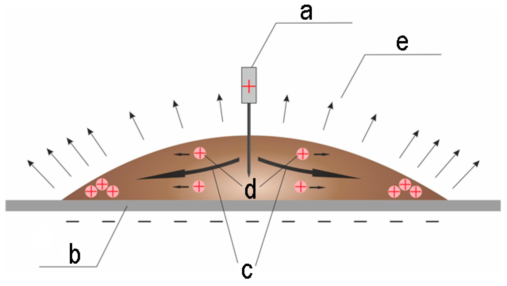
Figure 4a bottom line). As can be seen, the diameter of the forming spot of the deposit increases with increasing potential difference. The explanation behind this feature can be associated with the competition between dissipative and electrical forces which is schematically presented in
Figure 6.
Coulomb forces acting on colloidal particles moving in the compensation flow tend to take them out of the flows with subsequent deposition on a negative substrate. At the same time, their action is more effective in the center of the drop, where the intensity of the electric field is maximum. Closer to the edges of the drop, the field strength decreases, so the role of dissipative forces increases. This is probably the reason for the retention of the ring deposit at low voltages between the electrodes. As the potential difference increases, the field strength increases in the entire space occupied by the drop, as a result of which the central spot increases, and the width of the annular deposit decreases until it disappears.
As already mentioned above, no similar effect of the electric field on the formation of a deposit of a droplet of sample No. 2 was found. This may be due to the lack of charge in the colloidal particles of this colloid. Indeed, this sample is stabilized by shells of oleic acid molecules adsorbed on the surface of uncharged magnetite particles.
When magnetic and electric fields are applied simultaneously on an evaporating drop, their influence can either be increased or partially compensated by each other. The latter was demonstrated by the structures formed in the process of sample No. 1 drops evaporation when the non-homogeneous magnetic field was applied alongside negative potential applied to the substrate (
Figure 5a–c). Indeed, the action of an inhomogeneous magnetic field led to the formation of a deposit in the form of a round spot (disk) located in the center of the drop. In its turn, the action of the electric field contributes to the deposition of particles over the entire area of the drop due to the action of Coulomb forces, which concentrate NPs in the central area of the spot. Thus, in such a situation, there is some competition between magnetic and electrical forces. At a certain distance from the center of the drop, the magnetic and electric forces are compensating each other, resulting in an increased role of dissipative forces, which contribute to a decrease in the deposit area and the formation of an annular deposit along the droplet perimeter. As the result, the formed morphology of the formed deposits shows complex non-linear voltage between the electrodes as is seen in
Figure 5a–c. It can be assumed that the process of rim formation corresponded to a certain ratio of the components of the magnetic
and electric forces
, which, however, is rather difficult to establish for a given configuration of the electric and magnetic fields. Obviously, the problem of compensation for the effects of magnetic and electric fields requires further development.


