


High Temperature Oxidation of Enamel Coated Low-Alloyed Steel 16Mo3 in Water Vapor

Abstract
:1. Introduction
2. Experimental Method
2.1. Materials and Coatings
2.2. Oxidation in Water Vapor
2.3. Characterization
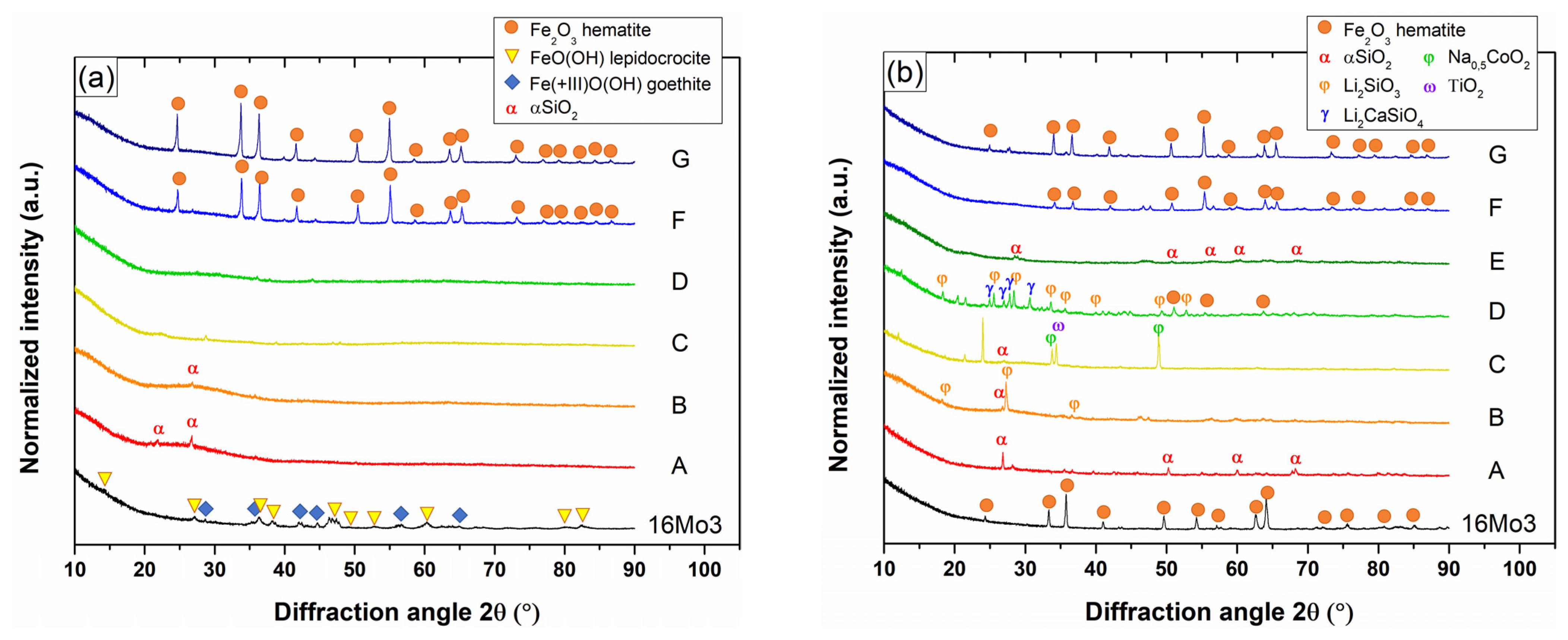
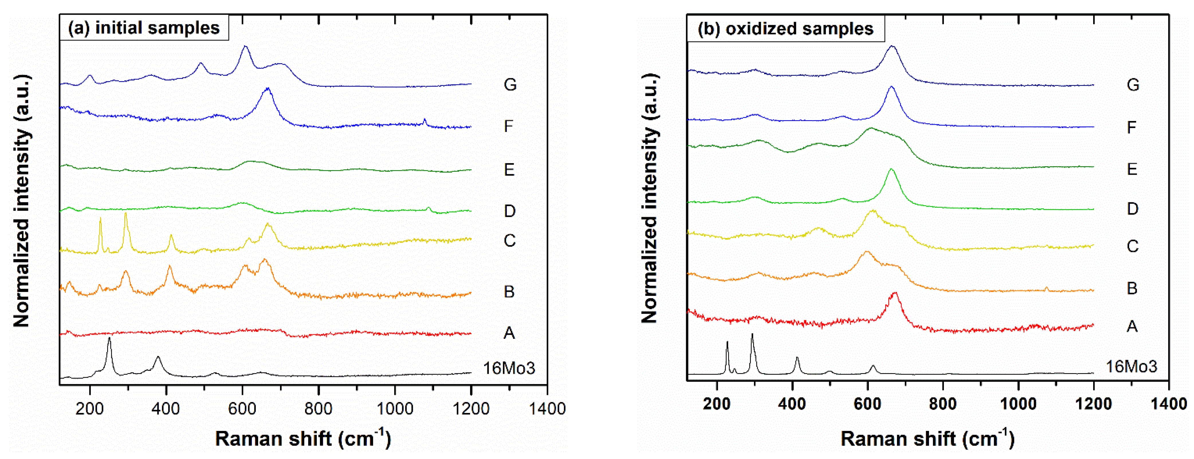
3. Results
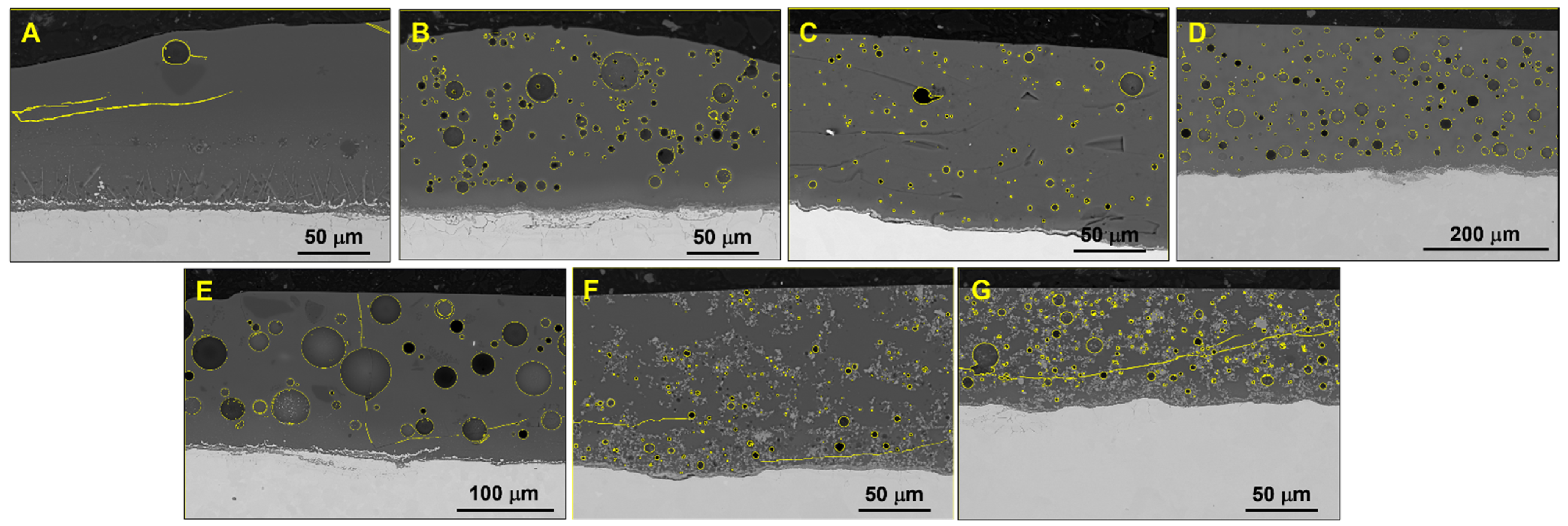
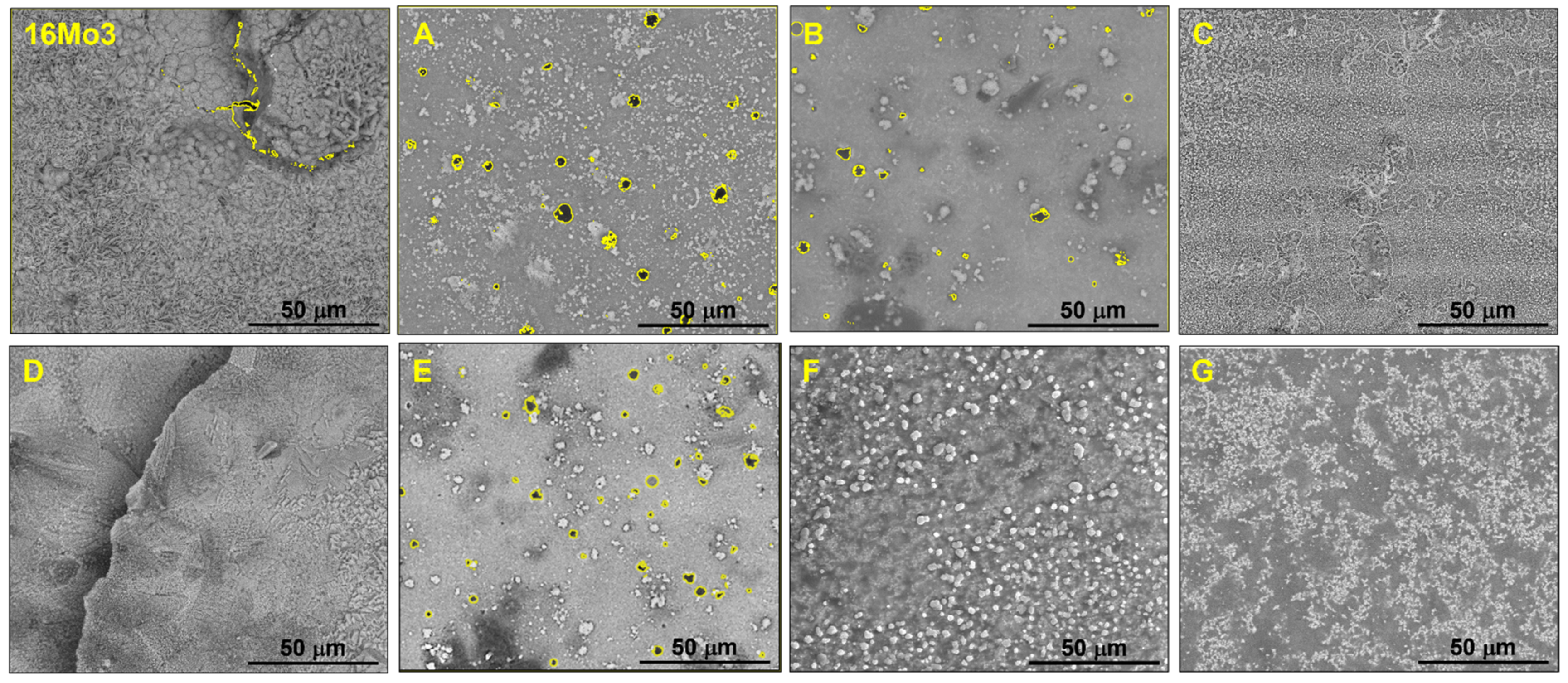
3.1. Coatings
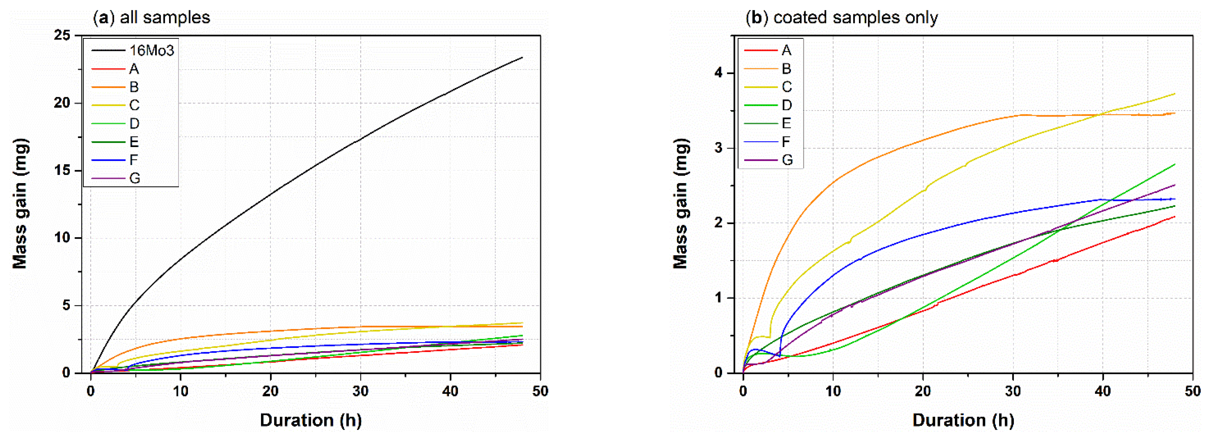
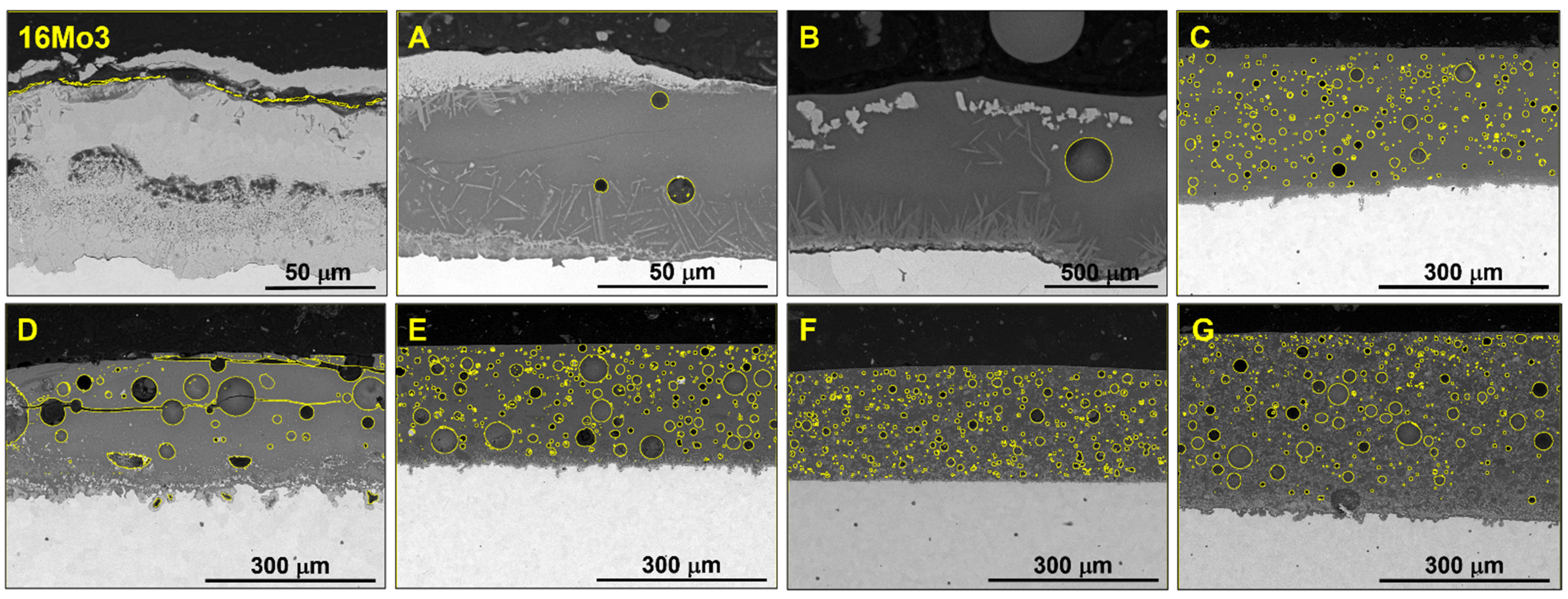
3.2. Oxidation in Wet Air
4. Discussion
4.1. Coatings
4.2. Oxidation
5. Conclusions
Author Contributions
Funding
Institutional Review Board Statement
Informed Consent Statement
Data Availability Statement
Acknowledgments
Conflicts of Interest
References
- Abu-Warda, N.; López, A.J.; Pedraza, F.; Utrilla, M.V. Corrosion Behavior of T24, T92, VM12, and AISI 304 Steels Exposed to KCl–NaCl–K2SO4–Na2SO4 Salt Mixtures. Mater. Corros. 2021, 72, 936–950. [Google Scholar] [CrossRef]
- Rząd, E.; Dudziak, T.; Polczyk, T.; Boroń, Ł.; Figiel, P.; Oziębło, A.; Chmielewska, D.; Synowiec, B.; Pichniarczyk, P. Sulfidation of Ceramic-Based Coatings Deposited on Low-Alloyed Steel 16Mo3 Exposed at High Temperature. J. Mater. Eng. Perform. 2021, 30, 8538–8550. [Google Scholar] [CrossRef]
- Boulesteix, C.; Pedraza, F.; Proy, M.; Lasanta, I.; de Miguel, T.; Illana, A.; Pérez, F.J. Steam Oxidation Resistance of Slurry Aluminum and Aluminum/Silicon Coatings on Steel for Ultrasupercritical Steam Turbines. Oxid. Met. 2017, 87, 469–479. [Google Scholar] [CrossRef]
- Boulesteix, C.; Kolarik, V.; Pedraza, F. Steam Oxidation of Aluminide Coatings under High Pressure and for Long Exposures. Corros. Sci. 2018, 144, 328–338. [Google Scholar] [CrossRef]
- Dhand, D.; Kumar, P.; Grewal, J.S. A Review of Thermal Spray Coatings for Protection of Steels from Degradation in Coal Fired Power Plants. Corros. Rev. 2021, 39, 243–268. [Google Scholar] [CrossRef]
- Kumar, S.; Kumar, M.; Handa, A. Combating Hot Corrosion of Boiler Tubes—A Study. Eng. Fail. Anal. 2018, 94, 379–395. [Google Scholar] [CrossRef]
- Galetz, M.C.; Bauer, J.T.; Schütze, M.; Noguchi, M.; Cho, H. Resistance of Coatings for Boiler Components of Waste-to-Energy Plants to Salt Melts Containing Copper Compounds. J. Therm. Spray Technol. 2013, 22, 828–837. [Google Scholar] [CrossRef]
- Jafari, R.; Sadeghimeresht, E.; Farahani, T.S.; Huhtakangas, M.; Markocsan, N.; Joshi, S. KCl-Induced High-Temperature Corrosion Behavior of HVAF-Sprayed Ni-Based Coatings in Ambient Air. J. Therm. Spray Technol. 2018, 27, 500–511. [Google Scholar] [CrossRef]
- Dudziak, T.; Hussain, T.; Simms, N.J.; Syed, A.U.; Oakey, J.E. Fireside Corrosion Degradation of Ferritic Alloys at 600 °C in Oxy-Fired Conditions. Corros. Sci. 2014, 79, 184–191. [Google Scholar] [CrossRef]
- Tejero-Martin, D.; Rezvani Rad, M.; McDonald, A.; Hussain, T. Beyond Traditional Coatings: A Review on Thermal-Sprayed Functional and Smart Coatings. J. Therm. Spray Technol. 2019, 28, 598–644. [Google Scholar] [CrossRef] [Green Version]
- Harrison, W.N.; Moore, D.G.; Richmond, J.C. Ceramic Coatings for High-Temperature Protection of Steel. J. Res. Natl. Bur. Stand. 1947, 38, 293. [Google Scholar] [CrossRef]
- Pavan, C.M.; Narendra, B.B.R. Review of Ceramic Coating on Mild Steel Methods, Applications and Opportunities. Int. J. Adv. Sci. Res. Eng. 2018, 4, 44–49. [Google Scholar] [CrossRef]
- Kasala, S.; Vidyavathy, M. Advanced Ceramic Coatings on Stainless Steel: A Review of Research, Methods, Materials, Applications and Opportunities. Int. J. Adv. Eng. Technol. 2016, 7, 126–141. [Google Scholar]
- Adraider, Y.; Pang, Y.X.; Nabhani, F.; Hodgson, S.N.; Sharp, M.C.; Al-Waidh, A. Laser-Induced Deposition of Alumina Ceramic Coating on Stainless Steel from Dry Thin Films for Surface Modification. Ceram. Int. 2014, 40, 6151–6156. [Google Scholar] [CrossRef]
- Vural, M.; Zeytin, S.; Ucisik, A.H. Plasma-Sprayed Oxide Ceramics on Steel Substrates. Surf. Coat. Technol. 1997, 97, 347–354. [Google Scholar] [CrossRef]
- Seraffon, M.; Simms, N.J.; Nicholls, J.R.; Sumner, J.; Nunn, J. Performance of Thermal Barrier Coatings in Industrial Gas Turbine Conditions. Mater. High Temp. 2011, 28, 309–314. [Google Scholar] [CrossRef]
- Sumner, J.; Encinas-Oropesa, A.; Simms, N.J.; Oakey, J.E. High Temperature Oxidation and Corrosion of Gas Turbine Component Materials in Burner Rig Exposures. Mater. High Temp. 2011, 28, 369–376. [Google Scholar] [CrossRef]
- Peters, M.; Leyens, C.; Schulz, U.; Kaysser, W.A. EB-PVD Thermal Barrier Coatings for Aeroengines and Gas Turbines. Adv. Eng. Mater. 2001, 3, 193–204. [Google Scholar] [CrossRef]
- Wells, J.; Chapman, N.; Sumner, J.; Walker, P. The Use of APS Thermal Barrier Coatings in Corrosive Environments. Oxid. Met. 2017, 88, 97–108. [Google Scholar] [CrossRef]
- Ramaswamy, P.; Seetharamu, S.; Rao, K.J.; Varma, K.B.R. Thermal Shock Characteristics of Plasma Sprayed Mullite Coatings. J. Spray Technol. 1998, 7, 497–504. [Google Scholar] [CrossRef]
- Shen, D.; Li, M.; Gu, W.; Wang, Y.; Xing, G.; Yu, B.; Cao, G.; Nash, P. A Novel Method of Preparation of Metal Ceramic Coatings. J. Mater. Process. Technol. 2009, 209, 2676–2680. [Google Scholar] [CrossRef]
- Pieraggi, B. Calculations of Parabolic Reaction Rate Constants. Oxid. Met. 1987, 27, 177–185. [Google Scholar] [CrossRef]
- Schäfer, G. Degradation of Glass Linings and Coatings. In Shreir’s Corrosion; Elsevier: Amsterdam, The Netherlands, 2010; Volume 3, pp. 2319–2329. ISBN 978-0-444-52787-5. [Google Scholar]
- Berdzenishvili, I.G. Functional Corrosion-Resistant Enamel Coatings and Their Adherence Strength. Acta Phys. Pol. A 2012, 121, 178–180. [Google Scholar] [CrossRef]
- Chen, M.; Li, W.; Shen, M.; Zhu, S.; Wang, F. Glass Coatings on Stainless Steels for High-Temperature Oxidation Protection: Mechanisms. Corros. Sci. 2014, 82, 316–327. [Google Scholar] [CrossRef]
- Rossi, S.; Russo, F.; Calovi, M. Durability of Vitreous Enamel Coatings and Their Resistance to Abrasion, Chemicals, and Corrosion: A Review. J. Coat. Technol. Res. 2021, 18, 39–52. [Google Scholar] [CrossRef]
- Son, Y.-K.; Lee, K.H.; Yang, K.-S.; Ko, D.-C.; Kim, B.-M. Prediction of Residual Stress and Deformation of Enameled Steel. Int. J. Precis. Eng. Manuf. 2015, 16, 1647–1653. [Google Scholar] [CrossRef]
- Dudziak, T.; Jura, K. High Temperature Corrosion of Low Alloyed Steel in Air and Salt Mist Atmospheres. Trans. Foundry Res. Inst. 2016, 56, 77–85. [Google Scholar] [CrossRef]
- Xiao, K.; Dong, C.; Li, X.; Wang, F. Corrosion Products and Formation Mechanism during Initial Stage of Atmospheric Corrosion of Carbon Steel. J. Iron Steel Resist. Int. 2008, 15, 42–48. [Google Scholar] [CrossRef]
- Majzlan, J.; Grevel, K.-D.; Navrotsky, A. Thermodynamics of Fe Oxides: Part II. Enthalpies of Formation and Relative Stability of Goethite (α-FeOOH), Lepidocrocite (γ-FeOOH), and Maghemite (γ-Fe2O3). Am. Mineral. 2003, 88, 855–859. [Google Scholar] [CrossRef]
- Kinebuchi, I.; Kyono, A. Study on Magnetite Oxidation Using Synchrotron X–Ray Diffraction and X–Ray Absorption Spectroscopy: Vacancy Ordering Transition in Maghemite (γ–Fe2O3). J. Mineral. Petrol. Sci. 2021, 116, 211–219. [Google Scholar] [CrossRef]
- Pérez, F.J.; Otero, E.; Hierro, M.P.; Gómez, C.; Pedraza, F.; de Segovia, J.L.; Román, E. Corrosion Protection of 13CrMo 44 Heat-Resistant Ferritic Steel by Silicon and Cerium Ion Implantation for High-Temperature Applications. Surf. Coat. Technol. 1998, 108–109, 121–126. [Google Scholar] [CrossRef]
- Dudziak, T. Steam Oxidation of Fe-Based Materials High Temperature Corrosion; Ahmad, Z., Ed.; IntechOpen: London, UK, 2016; pp. 1–25. ISBN 978-953-51-4727-5. [Google Scholar]
- Mysen, B.O.; Richet, P. Silicate Glasses and Melts: Properties and Structure; Elsevier: Paris, France, 2005; Volume 10. [Google Scholar]
- Saunders, S.R.J.; Monteiro, M.; Rizzo, F. The Oxidation Behaviour of Metals and Alloys at High Temperatures in Atmospheres Containing Water Vapour: A Review. Prog. Mater. Sci. 2008, 53, 775–837. [Google Scholar] [CrossRef]


| Coating Symbol | |||||||
|---|---|---|---|---|---|---|---|
| Oxide | A | B | C | D | E | F | G |
| SiO2 | 54.13 | 51.72 | 56.80 | 55.76 | 63.17 | 45.11 | 39.79 |
| Al2O3 | - | - | 2.89 | - | 2.22 | - | - |
| B2O3 | 18.10 | 15.79 | 7.22 | 2.02 | 8.32 | 15.08 | 12.14 |
| CaO | - | - | 4.34 | 3.01 | 2.00 | - | - |
| Na2O | 13.30 | 13.80 | 11.46 | 10.02 | 12.33 | 11.08 | 10.62 |
| K2O | - | 1.50 | 9.18 | 3.25 | 1.91 | - | 1.16 |
| ZnO | - | - | - | - | 3.05 | - | - |
| Li2O | 0.62 | 1.74 | - | 5.04 | 0.52 | 1.34 | |
| TiO2 | 6.14 | 7.53 | 5.69 | 1.99 | 3.05 | 5.11 | 5.79 |
| BaO | 1.99 | 2.51 | - | - | - | 1.66 | 1.93 |
| ZrO2 | - | - | - | 14.94 | - | - | - |
| F | 3.68 | 2.18 | - | 1.99 | 1.85 | 3.07 | 1.67 |
| CoO | 0.41 | 0.54 | 1.21 | 0.99 | 1.05 | 0.34 | 0.41 |
| MnO | 1.02 | 1.61 | 0.52 | 0.43 | 0.45 | 0.85 | 1.24 |
| NiO | 0.61 | 1.08 | 0.69 | 0.57 | 0.60 | 0.51 | 0.83 |
| Cr2O3 | - | - | - | - | - | 16.67 | 23.08 |
| Thickness (µm) | Porosity (vol.%) | Cracks (Orientation) | Coating-Substrate Interface | |
|---|---|---|---|---|
| A | 100 ± 25 | 1% | Parallel | Oxide and corrosion layer |
| B | 80 ± 15 | 3% | None | Thin oxide and corrosion layer |
| C | 110 ± 25 | 14% | None | Continuous thin oxide layer |
| D | 230 ± 15 | 25% | None | Thin oxide and corrosion layer |
| E | 170 ± 20 | 34% | Normal and parallel | Thin oxide and corrosion layer |
| F | 150 ± 10 | 15% | Parallel | Continuous thin oxide layer |
| G | 90 ± 5 | 18% | Parallel | Continuous thin oxide layer |
| Material | Time Interval; Oxidation Parameters “n” and “k” *,** | |||
|---|---|---|---|---|
| 16Mo3 | 0–1 h | 1–4 h | 4–48 h | – |
| transition | n = 1: linear * kl = 8.12∙10−8 | n = 0.65: parabolic ** kp = 3.17∙10−10 | ||
| A | 0–1 h | 1–7 h | 7–48 h | – |
| n = 0.49: parabolic ** kp = 1.20∙10−13 | transition | n = 1.05: linear * kl = 2.51∙10−9 | ||
| B | 0–20 min | 20–30 min | 30 min–7 h | 7–48 h |
| n = 0.51: parabolic ** kp = 1.20∙10−13 | transition | n = 0.75: sub-linear * kl = 2.32∙10−8 | n = 0.3: ~parabolic ** kp = 1.64∙10−12 | |
| C | 0–1 h | 1–4 h | 4–48 h | – |
| n = 0.45: parabolic ** kp = 2.28∙10−12 | breakaway without spallation | n = 0.55: parabolic ** kp = 4.80∙10−12 | ||
| D | 0–10 h | 10–48 h | – | – |
| transition | n = 1.4: super-linear * kl = 4.31∙10−9 | |||
| E | 0–30 min | 30 min–11 h | 11–48 h | – |
| transition | n = 0.55: parabolic ** kp = 1.39∙10−12 | n = 0.65: parabolic ** kp = 2.66∙10−12 | ||
| F | 0–30 min | 30 min–4 h | 4–40 h | 40–48 h |
| n = 0.56: parabolic ** kp = 1.69∙10−12 | breakaway without spallation | n = 0.53: parabolic ** kp = 1.66∙10−12 | evaporation | |
| G | 0–3 h | 3–13 h | 13–48 h | – |
| transition | n = 1.2: super-linear * kl = 4.37∙10−9 | n = 0.74: linear * kl = 2.49∙10−9 | ||
| Peaks Position (cm−1) | ||||||||
|---|---|---|---|---|---|---|---|---|
| Initial Samples: | 16Mo3 | A | B | C | D | E | F | G |
| ∼220 1 ∼250 1 ∼307 1 ∼347 1 ∼379 1 ∼529 1 ∼644 1 | - | ∼142 3 ∼223 2 ∼243 2 ∼295 2 ∼411 2 ∼500 2 ∼535 3 ∼605 2 ∼660 3 | ∼228 2 ∼245 2 ∼292 2 ∼412 2 ∼496 2 ∼616 2 ∼667 3 | - | - | ∼301 3 ∼533 3 ∼662 3 | ∼198 2 ∼264 2 ∼359 2 ∼431 2 ∼536 3 ∼607 2 ∼695 3 | |
| Oxidized samples: | 16Mo3 | A | B | C | D | E | F | G |
| ∼227 2 ∼248 2 ∼295 2 ∼413 2 ∼500 2 ∼615 2 ∼658 2 | ∼308 3 ∼538 3 ∼667 3 | ∼311 3 ∼460 3 ∼600 2 ∼674 3 | ∼465 3 ∼612 3 ∼682 3 | ∼304 3 ∼533 3 ∼662 3 | ∼312 3 ∼467 3 ∼610 2 ∼675 3 | ∼304 3 ∼535 3 ∼664 3 | ∼304 3 ∼534 3 ∼664 3 | |
| Thickness (µm) | Porosity (vol.%) | Cracks (Orientation) | Coating-Substrate Interface | |
|---|---|---|---|---|
| A | 50–60 | 2% | Parallel | Thick oxide and corrosion layer |
| B | 30–40 | 3% | None | Thick oxide and corrosion layer |
| C | 280 | 14% | None | Thick oxide and corrosion layer |
| D | 110–120 | 25% | Parallel | Thin oxide and corrosion layer |
| E | 225 | 34% | None | Thin oxide and corrosion layer |
| F | 200 | 15% | None | Continuous thin oxide layer |
| G | 300 | 18% | None | Continuous thin oxide layer |
Disclaimer/Publisher’s Note: The statements, opinions and data contained in all publications are solely those of the individual author(s) and contributor(s) and not of MDPI and/or the editor(s). MDPI and/or the editor(s) disclaim responsibility for any injury to people or property resulting from any ideas, methods, instructions or products referred to in the content. |
© 2023 by the authors. Licensee MDPI, Basel, Switzerland. This article is an open access article distributed under the terms and conditions of the Creative Commons Attribution (CC BY) license (https://creativecommons.org/licenses/by/4.0/).
Share and Cite
Boissonnet, G.; Rzad, E.; Troncy, R.; Dudziak, T.; Pedraza, F. High Temperature Oxidation of Enamel Coated Low-Alloyed Steel 16Mo3 in Water Vapor. Coatings 2023, 13, 342. https://doi.org/10.3390/coatings13020342
Boissonnet G, Rzad E, Troncy R, Dudziak T, Pedraza F. High Temperature Oxidation of Enamel Coated Low-Alloyed Steel 16Mo3 in Water Vapor. Coatings. 2023; 13(2):342. https://doi.org/10.3390/coatings13020342
Chicago/Turabian StyleBoissonnet, Germain, Ewa Rzad, Romain Troncy, Tomasz Dudziak, and Fernando Pedraza. 2023. "High Temperature Oxidation of Enamel Coated Low-Alloyed Steel 16Mo3 in Water Vapor" Coatings 13, no. 2: 342. https://doi.org/10.3390/coatings13020342