Review

Electrochemical Synthesis of Functional Coatings and Nanomaterials in Molten Salts and Their Application

Tananaev Institute of Chemistry of the Federal Research Centre “Kola Science Centre of the Russian Academy of Sciences”, 184209 Apatity, Russia
*
Author to whom correspondence should be addressed.
Coatings 2023, 13(2), 352; https://doi.org/10.3390/coatings13020352
Submission received: 2 December 2022 / Revised: 27 January 2023 / Accepted: 30 January 2023 / Published: 3 February 2023

Abstract

:
Nanomaterials are widely used in modern technologies due to their unique properties. Developing methods for their production is one of the most important scientific problems. In this review, the advantages of electrochemical methods for synthesis in molten salts of nanostructured coatings and nanomaterials for different applications were discussed. It was determined that the nanostructured Mo2C coatings on a molybdenum substrate obtained by galvanostatic electrolysis have a superior catalytic activity for the water-gas shift reaction. The corrosion-resistant and wear-resistant coatings of refractory metal carbides on steels were synthesized by the method of currentless transfer. This method also was used for the production of composite carbon fiber/refractory metal carbide materials, which are efficient electrocatalysts for the decomposition of hydrogen peroxide. The possibility to synthesize GdB6 nanorods and Si and TaO nanoneedles by potentiostatic electrolysis was shown.

1. Introduction

In recent years, nanostructured and nanoscale materials have been of great interest because of the unique mechanical, electrical, optical, and chemical properties possessed by such materials due to the small size of their components (e.g., grains, phase inclusions, layers, pores, etc.). The possibility of obtaining nanomaterials with a given structure provides a wide range of opportunities for the creation of new functional materials with unique sets of characteristics [1]. Nanomaterials are of great applied importance for solving problems of energy storage and conversion energy [2,3,4]; they are also used as catalysts [5,6,7,8], electrocatalysts [9], protective coatings and structural materials [10,11].
To the present day, a great number of different methods and approaches have been developed for the synthesis of nanomaterials [12,13,14,15]. According to [15] they can be divided into three groups: biological, physical, and chemical. In the current study, we will not describe all methods of nanomaterials synthesis in detail, but we will focus on some of the most common ones, including sol-gel [16,17,18,19,20], micellar [21,22,23], hydrothermal [24,25,26,27], vapor deposition [28,29,30,31,32], ultrasonic [33,34,35,36,37], microwave [38,39,40,41], and electrochemical [42,43,44,45,46,47,48,49,50].
Electrochemical methods of synthesizing nanomaterials and functional materials have a number of advantages over other methods [51]. For example:
  • electrolysis of melts using pulsed and reversible currents provides the ability to easily adjust the structure, thickness, porosity, roughness, grain size and texture of electroplated coatings and materials;
  • a large number of environments for synthesis (both aqueous and non-aqueous) used for various purposes;
  • electrodeposition parameters determined at a laboratory scale can be transferred to the industrial scale;
  • high purity of the obtained coatings and materials even if low-quality initial reagents are used, since metals are refined in the process of electrolysis;
  • low operating costs and low costs of electrochemical equipment.
On the other hand, the use of molten salts such as chlorides and fluorides of alkali metals as a medium in the electrochemical synthesis of nanomaterials makes it possible to increase the current density due to a high electric conductivity and thereby to intensify the synthesis processes. Electrochemical synthesis in molten salts leads to the appearance of strong electric and magnetic fields in the near-electrode layer (the electric field strength near the cathode is 109–1010 V m−1 [52]). Therefore, the synthesis can proceed under conditions far from the thermodynamical equilibrium, which significantly expands the number of obtained compounds and their phase modifications as compared to other methods of nanomaterial production.
A large number of studies are devoted to obtaining silicon-based nanomaterials in various molten salts using electrochemical methods [53,54,55,56,57,58,59,60,61]. For example, methods of producing silicon-based nanomaterials for utilization in advanced power engineering are reviewed in [55,57,59,60,61]. By varying the electrolyte composition, electrolysis parameters and process temperature, it becomes possible to synthesize nanowires and nanotubes.
The synthesis of carbon-based nanomaterials in molten salts has been the subject of many reviews and articles. In review [62], the methods and mechanisms of synthesis of nanomaterials based on graphene and its oxide in various melts are discussed in detail. Reducing the amount of carbon dioxide emissions in the atmosphere has become an urgent problem, and the electroreduction of CO2 in molten salts can contribute to solving this challenge. In works [63,64,65,66,67,68,69,70,71,72,73], the processes and mechanisms of electroreduction of carbon dioxide in various melts leading to the production of various carbon nanoparticles have been investigated. One study [64] reveals the effect of the electrolysis temperature in molten Li-Na-K carbonates on the shape of carbon nanomaterials. At a process temperature below 850 K, carbon nanosheets are formed on the cathode, and nanotubes are formed at a higher temperature. In the paper [65], the principle possibility of carbon nanotube generation by the electrolysis of molten salts saturated by carbon dioxide was shown. Kushkov et al. [68] found that, depending on the experimental conditions, the electrolysis of molten alkali metal carbonates led to the synthesis of carbon nanotubes or fullerenes C60 or C70. Electrochemical methods to synthesize carbon nanotubes and various carbon nanostructures from CO2 in molten CaCl2-NaCl-CaO were discussed in [72].
For the nanotechnology of carbon materials, it is of great interest to produce nanodiamonds in molten salts. It was shown in [74] that single Li2CO3 nanocrystals (<30 nm) can be synthesized by the injection of moist CO2 into molten LiCl containing Li2O. The subsequent cathodic polarization of a graphite rod immersed in the molten salt led to the formation of carbon-encapsulated lithium carbonate nanoparticles. Upon heating in ambient-pressure air, these nanostructures acted as high-pressure nanocrucibles, creating diamond crystallites within lithium carbonate.
The electrochemical methods allow to synthesize carbides of different metals, which can be used for surface protection against oxidation or corrosion and as catalysts or electrocatalysts. In studies [75,76] voltammetric investigations of tungsten and carbon-containing melts were carried out to find the conditions for a high-temperature electrochemical synthesis of nanostructured tungsten carbide coatings and nanopowders. Binary tungsten-molybdenum carbide nanopowders were fabricated by high-temperature electrochemical synthesis from tungstate–molybdate–carbonate melts [77].
Analysis of available literature data shows that electrochemical synthesis in molten salts is a promising method for obtaining coatings and nanomaterials.
Of course, this article is not a complete review of all the data available in the literature on the production of coatings and nanomaterials in molten salts. The aim of the present work was to introduce our results on electrochemical synthesis in molten salts of nanostructured coatings and nanomaterials used for different applications.

2. Materials and Methods

In this work, we used chloride-fluoride electrolytes for the synthesis of nanostructured coatings and nanomaterials.
Sodium and potassium chlorides (Prolabo 99.5% min) were recrystallized in distilled water to remove various insoluble impurities. Afterwards they were calcined in a muffle furnace at 773 K. Then, NaCl and KCl were mixed (with a molar ratio of 1:1) and evacuated to a residual pressure of 0.6 Pa at 298, 473, 673, and 823 K; following that, the NaCl and KCl mixture was melted in a purified and dried argon atmosphere.
Sodium fluoride (Prolabo 99.5% min) was refined from impurities using the method of directional crystallization, which is described elsewhere [78].
Li2CO3 (Sigma-Aldrich, St. Louis, MI, USA, 99% min) and Na2MoO4·H2O (Sigma-Aldrich, 99.5% min) were dehydrated for 24 h at 473 K. Chromium trichloride (Sigma-Aldrich, anhydrous, 99.99% min) was used without additional treatment.
Potassium heptafluoroniobate, heptafluorotantalate, and hexafluorosilicate were synthesized at the experimental facility of the Tananaev Institute of Chemistry-Subdivision of the Federal Research Centre, at the Kola Science Centre of the Russian Academy of Sciences. The content of metallic impurities in the synthesized salts did not exceed 10−3 wt.% according to mass spectroscopy data. The purification methods of K2NbF7, K2TaF7, and K2SiF6 are described in literature [79,80,81].
Potassium tetrafluoroborate (Sigma-Aldrich, 99.99% min) was used without additional treatment. GdF3 was synthesized by heating a mixture of Gd2O3 and [NH4][HF2] in an argon atmosphere [78]. The procedures for obtaining K3TaOF6 and CsCl were described in details elsewhere [82].
A detailed description of the experimental setup, instruments and materials used for synthesis, identification and investigation of the morphology, and properties of the synthesized coatings and nanomaterials are given in [83,84,85].
Other specific techniques are described in the sections below.

3. Results and Discussions

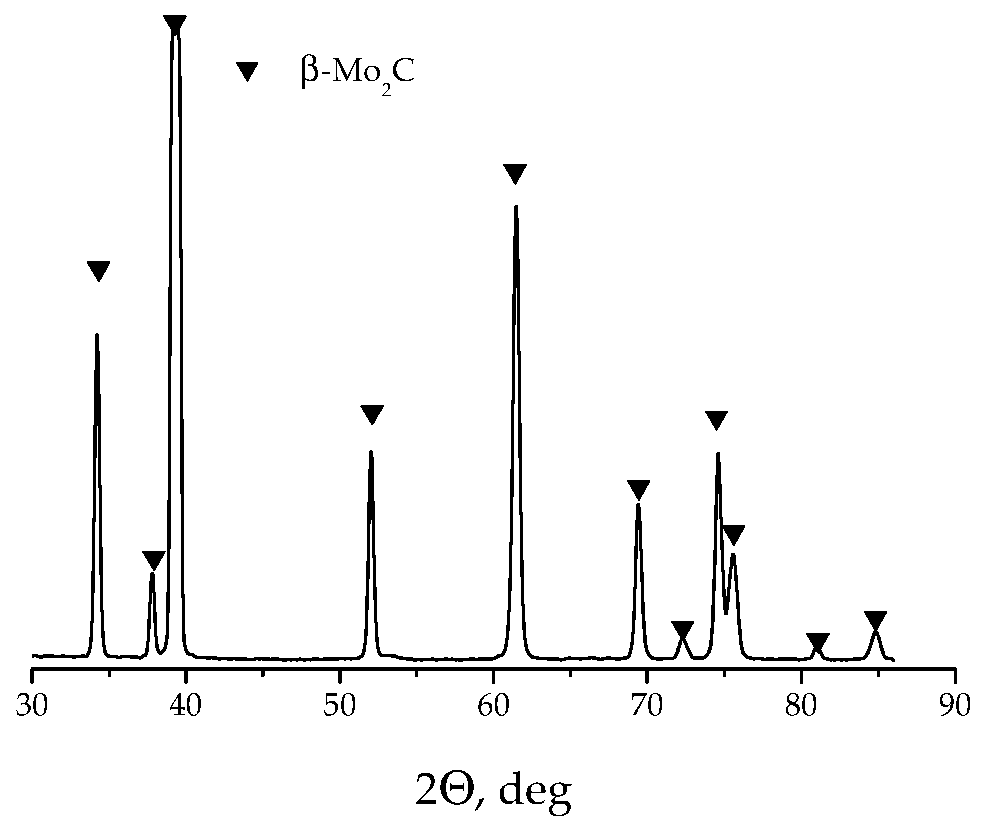
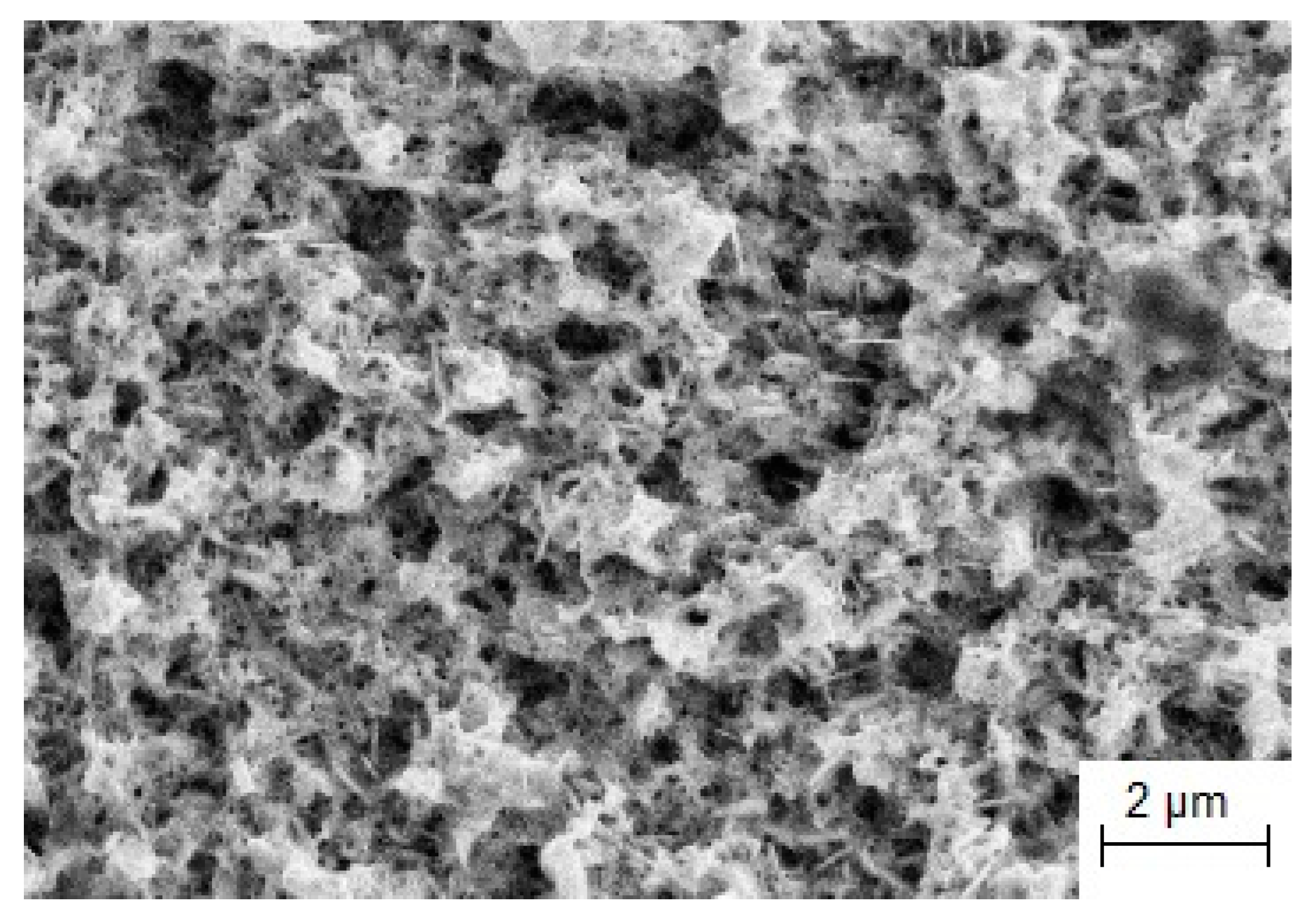
3.1. Nanostructured Catalytic Coatings Mo2C

One of the promising areas of hydrogen energy is the direct placement of an integrated device on board a vehicle, which includes a fuel processor in combination with a fuel cell. As a result of the transformation of gasoline or natural gas, hydrogen is obtained, which contains about 12 vol % CO. The carbon monoxide steam reforming reaction (SRR) is used to remove carbon monoxide from the hydrogen-rich gas, since CO is a catalytic poison to the proton exchange membrane of the fuel cell. The high-temperature steam reforming reaction is usually carried out on ferrochrome (Fe3O4/Cr2O3) as a catalyst at temperatures of 573–723 K, which makes it possible to reduce the CO content to 2 vol % and obtain an additional amount of hydrogen. This product is then subjected to a low-temperature steam reforming reaction using a Cu/ZnO/Al2O3 catalyst at a temperature range of 433–523 K, which reduces the CO concentration to 0.1% by volume. However, the low-temperature catalyst occupies approximately 70% of the volume of the entire fuel processor catalytic system and is also pyrophoric due to the oxidation of Cu to Cu2O or CuO, making it potentially hazardous. Strict temperature control is necessary to carry out a low-temperature SRR, which makes the Cu/ZnO/Al2O3 catalyst impractical.
Thus, the search for a catalyst with high activity at 473–523 K, capable of reducing the CO concentration to 0.1 vol % for use in automobiles and other vehicles, remains relevant. A new class of catalytic systems based on refractory metal carbides can be used for the carbon monoxide steam reforming reaction.

3.1.1. Electrochemical Synthesis

Based on the analysis of the peculiarities of molybdenum and carbon electrodeposition, an NaCl-KCl-Li2CO3-Na2MoO4 chloride-carbonate-molybdate melt was chosen for electrochemical synthesis. As the substrate, molybdenum plates (99.99 wt.% Mo), 40 mm long, 10 mm wide, and 0.1 mm thick were used. Electrochemical synthesis of Mo2C coatings was carried out at the following conditions: temperature 1123 K, cathodic current density 5 mA cm−2, time of electrolysis 7 h, and the glassy carbon (SU-2000) ampoule was used as the anode. X-ray phase and microstructural analyses, scanning electron microscopy, and the BET method were used to characterize the obtained coatings.
It is important that the obtained coatings are β-Mo2C monophase semi-carbide with a hexagonal crystalline lattice (Figure 1). At the same time, bulk Mo2C contains at least several weight percent of cubic molybdenum carbide, which significantly reduces its catalytic activity and stability in the carbon monoxide steam reforming reaction. The formation of hexagonal Mo2C during electrochemical synthesis is the result of specific electrocrystallization conditions (electric field, double layer, and high temperature) [52].
Joint electroreduction of MoO42− and CO32− ions resulted in the formation of 50 μm thick Mo2C coatings and can be in general described by the reaction:
2MoO42− + CO32− + 16e → Mo2C + 11O2−.
The morphology of the Mo2C coating is presented in Figure 2. The figure shows that the obtained coating is nanostructured, and consists of a large number of pores with sizes ranging from 300 nm to 3 μm and Mo2C nanoneedles.

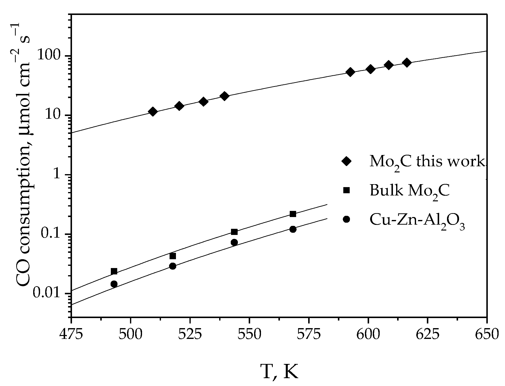
3.1.2. Catalytic Activity

The steady-state steam reforming reaction rate for the Mo2C/Mo composition was three orders of magnitude higher than for the Mo2C bulk phase and the commercial Cu/ZnO/Al2O3 catalyst (Figure 3).
The specific surface area (BET surface) of the Mo2C coating was 38 m2 g−1. The BET surface of bulk Mo2C was much higher (61 m2 g−1) [86]. Despite this, the catalytic activity of the bulk Mo2C was much lower than that of the catalysts obtained by electrolysis. This can be explained by the presence of cubic modification in the bulk Mo2C composition, which significantly reduces the SRR rate.
Methane formation was not observed throughout the entire temperature range in which the Mo2C/Mo coatings were tested. The catalytic activity remained constant over 5000 h of testing. The coatings also remained stable during cyclic temperature tests, while the activity of industrial catalysts decreased.
Thus, by electrochemical synthesis in molten salts, we obtained a new Mo2C/Mo-based catalytic system for a low-temperature steam reforming reaction. The catalytic activity of the composition, obtained by simultaneous reduction of electroactive MoO42− and CO32− particles, was three orders of magnitude higher than that of the bulk Mo2C and commercially available Cu-ZnO-Al2O3 catalyst.

3.2. Wear and Corrosion Resistence Coatings on Steels

The main requirements for hard alloys as cutting, milling, and drilling tools are wear resistance, chemical stability at high temperatures, and superior mechanical properties. Current research shows that the local temperature on the surface of these tools increases greatly during tool usage, resulting in oxidation, changes in composition, and surface degradation over time. In addition, these materials sometimes operate in aggressive environments. The corrosion rate of materials is significantly affected by the pH of the environment. Materials based on the refractory metal carbides show a good resistance in acidic electrolytes [87].
The modification of a tool’s surface with films and coatings of different compositions can be carried out by many methods. These coatings determine the surface properties [88,89]. Currently NbC and TaC, with the addition of WC, are effectively used as cutting tools [90]. Tantalum carbide is used in the engine and aerospace industries due to its resistance to high-temperature oxidation [91].
Various techniques of obtaining chromium carbide coatings, such as chemical vapor deposition [92], metallothermic reduction of Cr2O3/C mixtures [93], and magnetron sputtering [94] were reviewed in [92,93,94,95,96]. It is shown that the deposition of Cr2C3 as a coating on steel leads to an increase in the hardness and wear resistance and reduces the friction coefficient [93,94].
In [97], different methods of synthesis of protecting coatings are discussed. It was concluded [97] that coating deposition by molten salt electrolysis is a prospective way for obtaining smooth and uniform coatings on complex-shape samples.
Previously, we have thoroughly studied [98] the processes of alloy formation during electrodeposition of chromium on the surface of steels with the formation of chromium carbide coatings of different compositions.

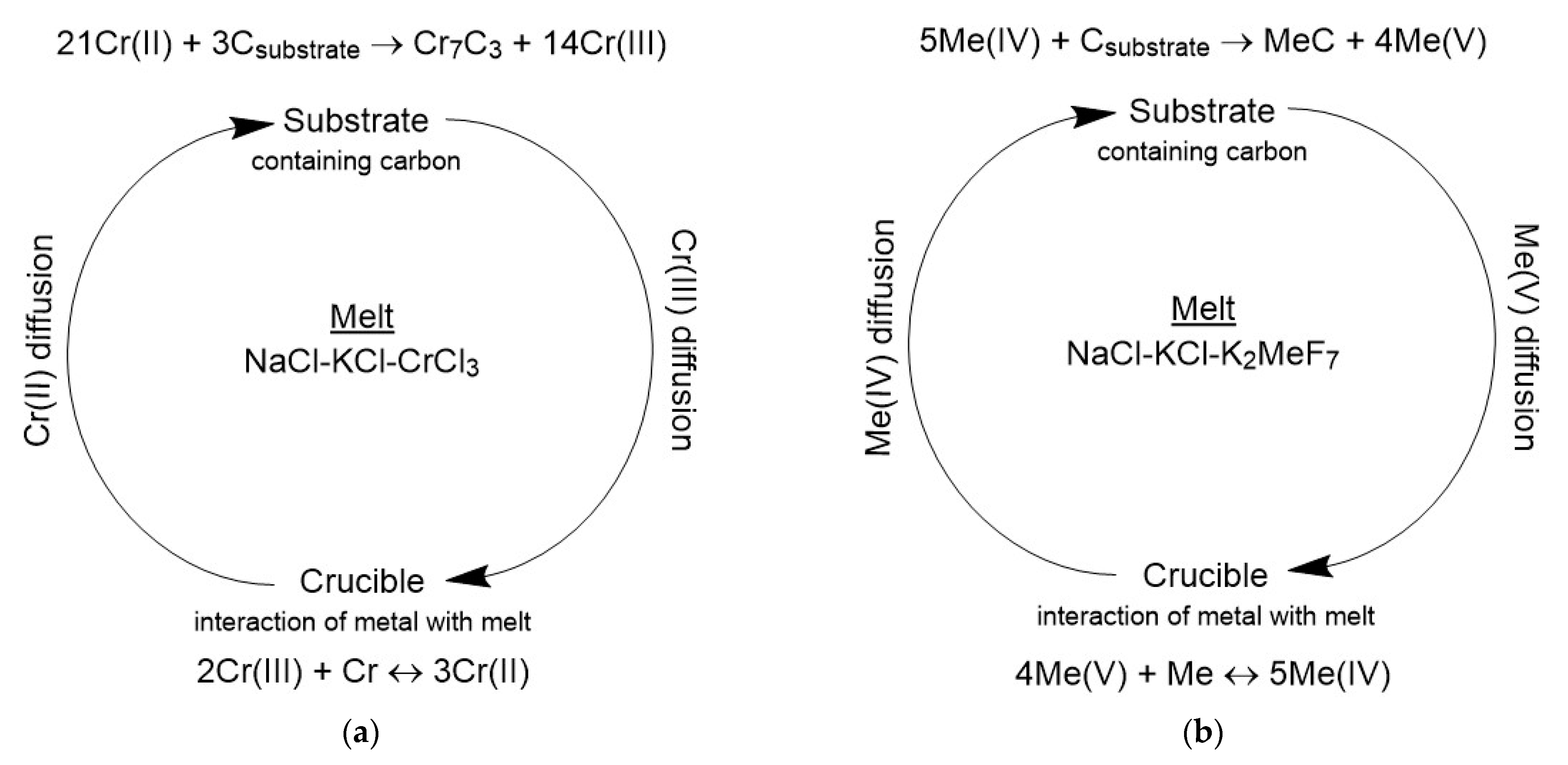
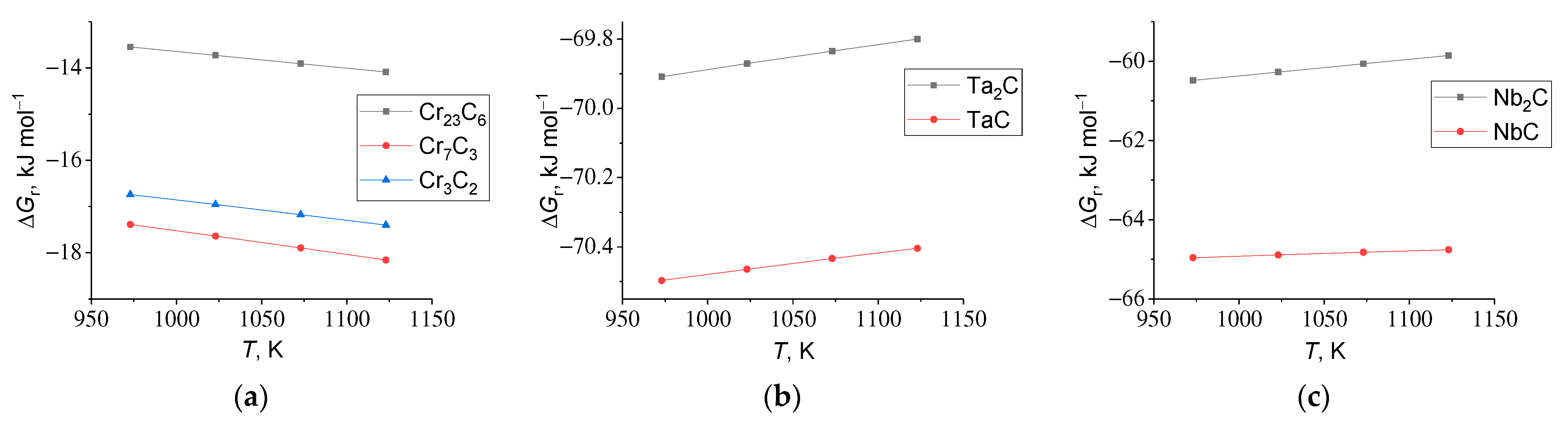
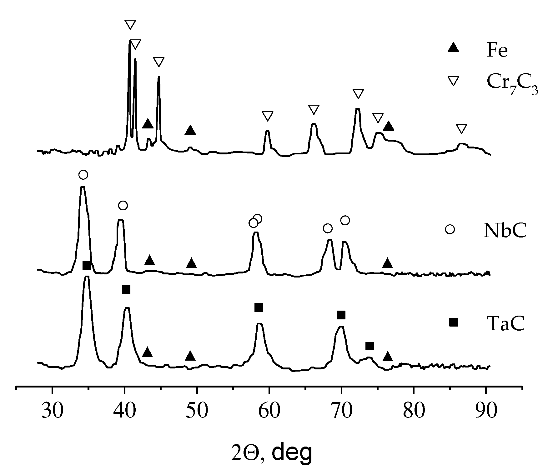
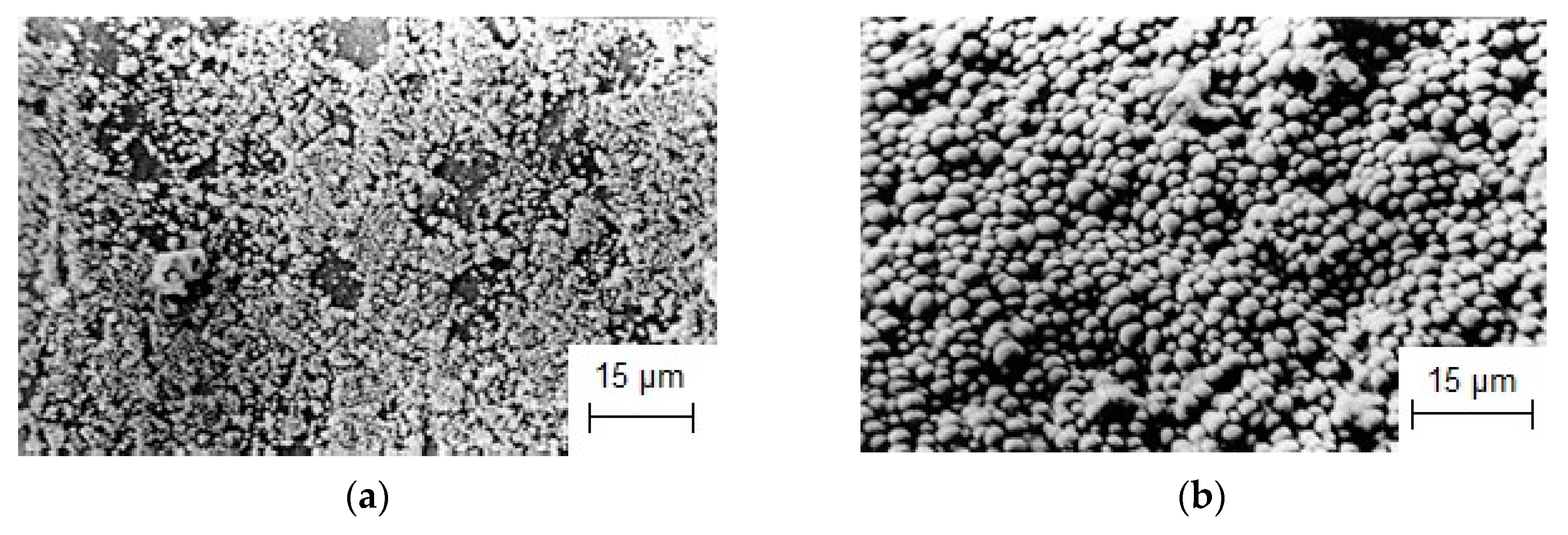
3.2.1. Currentless Transfer: A Simple Way to Obtain Refractory Carbide Coatings

An alternative method for synthesizing coatings of refractory metal carbides on steels is currentless transfer (CT) [99]. It is important to note that CT is an electrochemical method, and synthesis by CT is subject to the laws of electrochemical thermodynamics, kinetics, and reaction diffusion in solids [98,100,101,102].
A schematic diagram of CT in molten salts is shown in Figure 4. During the process, metal-salt reactions occur and metal cations with an intermediate oxidation state are formed disproportionately on the surface of steel (or another carbon-containing material) to form a refractory metal carbide and a cation in a higher oxidation state. The driving force of the CT is the Gibbs (ΔGr) energy of the carbide-forming reaction. The carbide with the smallest (more negative) value of ΔGr will be formed [99].
Figure 5 shows the temperature dependencies of the Gibbs energy per 1 mole of the product for the formation of chromium, tantalum, and niobium carbides from the elements. It was shown that the formation of Cr7C3, TaC, and NbC carbides is the most preferable. It also follows from the thermodynamic data that the synthesis of chromium carbides on steels is preferable at higher temperatures, as evidenced by the decrease in ΔGr with increasing temperature. For niobium and tantalum carbides the temperature dependence of ΔGr is different, and ΔGr increases (becomes less negative) with increasing temperature. However, with increasing temperature the melt viscosity decreases, and diffusion fluxes of metal complexes in various degrees of oxidation through the electrolyte increase. This leads to the intensification of NbC and TaC formation on steels with increasing temperature despite being less thermodynamically favorable.
Based on these considerations, the optimal conditions for the synthesis of carbide coatings by the CT method were selected. An equimolar NaCl-KCl mixture was used as an electrolyte, the process temperature was 1173 K, the concentrations of refractory metal salts (CrCl3, K2TaF7 and K2NbF7) were 30 wt.%, and the synthesis time varied from 3 up to 24 h [103].
The obtained coatings were analyzed by XRD, which showed the formation of Cr7C3 TaC and NbC coatings (Figure 6), in perfect agreement with the thermodynamic data. The peaks of diffraction patterns corresponding to the substrate are caused by the insignificant thickness of the synthesized coatings.

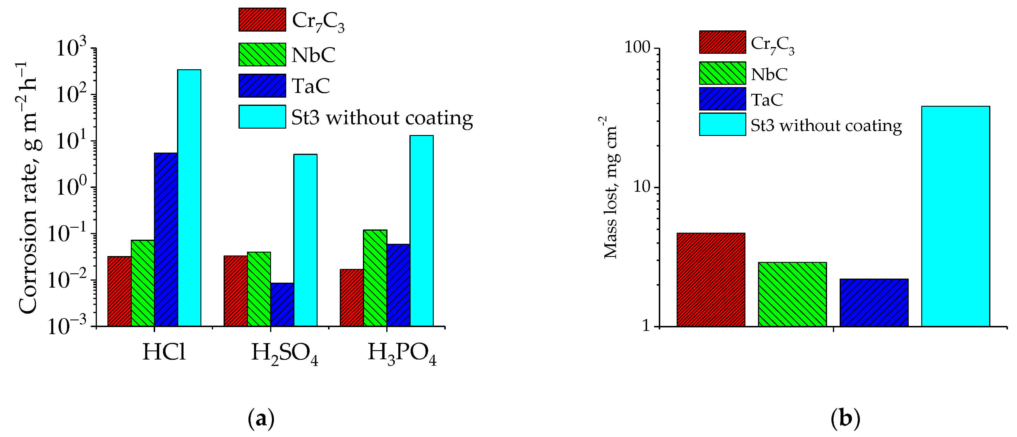
3.2.2. Protective Properties of Refractory Carbide Coatings

Cross-section was used to determine the thickness of synthesized refractory metal carbide coatings. In general, the thickness of the coatings obtained by the CT method depends on the duration of the process, the diffusion rate, and the carbon content in the substrate. In our case, the coating thicknesses were 1–2 microns. The morphologies of niobium carbide coatings formed at various synthesis durations on St.3 steel are presented in Figure 7. The coatings were composed of densely packed spherical particles with a diameter of 1–2 µm. If the synthesis time was 3 h (Figure 7a), the coating was not continuous. To obtain continuous coatings, the synthesis time was increased to 8 h (Figure 7b).
Samples coated with Cr7C3, NbC and TaC were tested for corrosion resistance in concentrated mineral acids and for wear resistance by the following methods. The corrosion rate was determined by a gravimetric method using cylindrical samples with a length of 30 mm and a diameter of 7 mm. After deposition of the coatings and electrolyte removal, the samples were degreased with refined ethyl alcohol. The corrosion rate was determined at 298 K for 48 h as a mass loss of the sample through a surface area unit per unit of time. At the end of the sample exposure in concentrated mineral acids, corrosion products were removed mechanically, the samples were degreased again, and were weighed on analytical scales with an accuracy of up to 1 × 10⁻⁵ g.
The wear rate was measured as the weight loss of the coated sample relative to the original sample, on the SMTs-2 friction machine (LLC “Precision Instruments”, Ivanovo, Russia) at a specific load of 5 mPa, in transformer oil, at a slip velocity of 1.2 m s−1, and on a path segment of 2000 m.
The results of the corrosion and wear resistance tests are shown in Figure 8. Refractory metal carbide coatings substantially reduced the corrosion rate of steel samples in concentrated acids, especially for H2SO4 and HCl (Figure 8a). Of course, the quality of obtained coatings (porosity) affects the results to a certain degree. Due to high hardness values of refractory metal carbides and their good adhesion with the substrate, the loss of mass as a result of mechanical wear is reduced by 3–5 times compared with the reference sample (Figure 8b).
Our studies showed that to achieve a good corrosion resistance of samples with Cr7C3, NbC and TaC coatings, the required thickness of protective coatings should be 1–3 µm. At the same time, thin films with a thickness of 100–700 nm obtained at a shorter duration of synthesis are sufficient only to impart resistance to mechanical wear.
The combination of high corrosion and wear resistance makes the investigated coatings a promising material for aggressive media with abrasive wear. These coatings have been tested in industrial facilities. Deposition of niobium carbide coatings on parts of crude oil pumps improved their lifetime by 3–4 times (tested by LLC “New technology”, Russia, Nefteyugansk). Tests carried out by LLC “Ecotech” (Russia, Apatity) showed that the coatings of Cr7C3 or TaC on the rubber-cutting knifes made of St3 can increase their wear resistance and increase a tool service life by a factor of 2.0 (Cr7C3) and 2.5 (TaC).

3.3. Electrocatalytic Compositions Carbon Fiber/Refractory Metal Carbide

The application of cheap refractory metal carbides as catalysts and electrocatalysts instead of expensive noble metals is preferable for some oxidation or reduction processes [104]. Carbon fibers can serve as a substrate for the electrochemical deposition of coatings and crystals of refractory metal carbides from molten salt media. Obtaining refractory metal carbide-carbon fiber composites using such processes is operationally quite simple and not energy consuming.
Conducting electrocatalytic reactions instead of traditionally catalytic ones has a number of advantages. For example, it is possible to control the reaction kinetics by adjusting the potential, which directly affects the activation energy of the conducted process [105], as well as the environmental friendliness of electrocatalysis since an electron is involved in the reaction as an oxidizing or reducing agent, and there are no hazardous reaction by-products [105,106].

3.3.1. Synthesis of Refractory Metal Carbide Coatings on Carbon Fibers

The synthesis of transition metal carbide/carbon fiber composites was carried out by the CT method described above (Section 3.2.1). X-ray diffraction patterns of all synthesized composites are presented in Figure 9. According to XRD analysis, tantalum carbide had a cubic structure with a border-centered crystal lattice, niobium carbide had a cubic crystal lattice, and crystals of the Mo2C phase had a hexagonal structure.
Figure 10 shows micrographs of carbon fibers coated with tantalum carbide (a) and a cross-section of a single fiber (b). The micrographs show that the fibers were not spliced together, and the coatings were uniform both in the cross-section and along the fiber.
Carbon fibers with niobium carbide coatings are shown in Figure 11. The diameter of the carbon fibers was approximately 7 ± 1 μm. The thickness of the tantalum and niobium carbide coatings on the carbon fiber was from a few tens of nanometers to a couple hundred nanometers. No other compound phases were detected between the carbon fiber and the coating.
The Mo2C phase was also obtained on carbon fibers by CT in molten salts. The melt in this case contained sodium molybdate, Na2MoO4. It was found that increasing the exposure time of the carbon fiber in the melt leads to an increase in the amount of Mo2C crystals. The Mo2C crystals had a well-defined structure with a crystal size of ~7–21 μm (Figure 12).

3.3.2. Investigation of the Electrocatalytic Activity of Composites Based on Refractory Metal Carbide on Carbon Fiber

The kinetics of electrocatalytic decomposition of hydrogen peroxide on the surface of refractory metal carbides (TaC, NbC, Mo2C) can be investigated by measuring the volume of evolved gases per unit of time. Decomposition of hydrogen peroxide proceeds with the emission of gaseous products: oxygen is emitted at the anode, which was the studied composite material, and hydrogen is emitted at the cathode, which was an uncoated carbon fiber.
To compare the results of studying the kinetics of the hydrogen peroxide decomposition reaction on refractory metal carbide-carbon fiber composites with the kinetics of the same reaction using traditional catalysts as copper and platinum, we used 5 mm2 metal electrodes. However, it is difficult to estimate the surface area of electrodes made of composites of refractory metal carbides. Their specific surface area is 5–15 m2 g−1. In all our experiments, the same linear dimensions of the composite electrodes were used, and the same immersion depth in hydrogen peroxide solution was maintained.
The graphical analysis of the kinetic dependences (Figure 13) established the zero order of the electrocatalytic reaction of hydrogen peroxide decomposition [107]. It can be described by the kinetic equation of the form υ = k, where υ is the reaction rate, and k is the reaction rate constant.
The activation energies of the studied H2O2 decomposition were calculated from experimental data obtained at different temperatures in steps of 10 K. Figure 13 shows the kinetic data at 303 K for all studied composites. Similar dependencies were also observed at higher temperatures, so only one example is presented in this article. It can be seen that the rate of electrocatalytic reaction of hydrogen peroxide decomposition increases in the following series: Mo2C/C < TaC/C < Pt < Cu < NbC/C.
The obtained values of the rate constants for the hydrogen peroxide decomposition at different temperatures were used to calculate activation energies. It was found that the activation energy values for the Mo2C/C, TaC/C, Pt, Cu and NbC/C electrodes are equal to 107.2, 82.2, 74.8, 48.2, and 37.1 kJ mol−1, respectively.
It should be noted that the activation energy of the hydrogen peroxide decomposition process is given here from the general chemical point of view. Since it is impossible to reliably determine the value of the potential difference between the electrode surface and any point in the solution, we do not have a reliable method for the experimental determination of the activation energy for the specific electrode process. Therefore, the calculated activation energies are given for a formal decomposition process taking place on the anode.
It has been established that the reaction rate does not change over time, in accordance with the zero-order kinetic equation, which has no dependence on the concentration of reacting substances, and the diffusion rate to the surface of electrode is smaller than the rate of chemical transformation.

3.4. Electrochemical Synthesis of Gadolinium Borides Nanorods in Molten Salts

Highly pure rare earth metals and their refractory compounds with oxygen, carbon, nitrogen, and boron are widely used in special alloys in metallurgy, semiconductor electronics and laser techniques; they are used for production of permanent magnets, new types of catalysts, optical glasses, and hydrogen accumulators. Gadolinium boride is especially prospective in nuclear engineering for neutron adsorption. Nanomaterials based on gadolinium hexaboride are promising materials for modern technology due to their unique electric, magnetic, and optical properties. For example, GdB6 nanorods are characterized by a very low electron work function (∼1.5 eV), which makes this nanomaterial very interesting for the fabrication of point electron emitters. GdB6 nanorods are strong light absorbers in the near infrared region, and they are transparent to visible light.
The traditional manufacturing of rare-earth borides is based on the direct reaction of pure initial components at high temperatures (up to 2700 K), which negatively affects the microstructure of the product. Electrochemical synthesis at moderate temperatures (973–1023 K) is a cost-effective alternative to direct reaction techniques and it has been successfully applied to the production of high-quality refractory borides. Electrochemical techniques provide not only the required stoichiometry and narrow size distribution of the product, but also the designated morphology. Prior to our studies, there was no information on the preparation of GdB6 nanorods and nanowires in the literature.
For the electrochemical synthesis of GdB6 it is necessary to know the electrochemical behavior of boron and gadolinium in their joint presence in the melt. Waves on the voltammogram in the NaCl-KCl-NaF-GdF3-KBF4 melt (Figure 14) reflected the boron reduction from BF4- complexes (RB, the least negative wave at about −0.8–−1.0 V) and gadolinium discharge on a boron deposit (RGd-B, at potentials −1.5 V and −1.8 V). The ascending section on the voltammogram corresponds to the discharge of gadolinium and alkali metal cations. Significant differences in the electroreduction potentials of boron and gadolinium allows us to make a reasonable assumption about the so-called “kinetic regime” [52] of their compound synthesis in the melt. Thus, the hexaboride can be synthesized only at current densities higher than the limiting current density for a more positive constituent (boron) discharge process. During co-deposition with boron, gadolinium reduced not on a silver surface, but on the layer of already deposited boron. The high depolarization value of this process leads to the formation of boron-gadolinium compound at potentials near −1.5 V and −1.8 V.
Potentiostatic electrolysis (7 h duration) was carried out, at potentials −1.5 V and −1.8 V. The deposits were scraped off and any electrolyte adhering to the deposits were leached with a warm dilute HCl, then 2% NaOH, and finally washed with distilled water and ethanol. XRD analysis identified the products of electrolysis as gadolinium hexaboride [78]. At the potential of –1.5 V the gadolinium hexaboride was synthesized in the form of coral-like dendrites. Micro- and nanorods were obtained at the potential of −1.8 V (Figure 15). Along with nanorods, a GdB6 nanowire was also formed on the cathode; the length of the nanostructure significantly exceeded its diameter, and, in some cases, the nanowire was bent. The intercalation mechanism was suggested for the formation of nanorods and nanowire [78].

3.5. Synthesis of One-Dimensional Nanostructures: Si and TaO Nanoneedles

One-dimensional nanomaterials, such as nanorods, nanotubes, nanowires, and nanofibers, are promising for catalysis and electrocatalysis [108]. Firstly, this is due to their large surface area with a high concentration of active centers [109]. Secondly, such nanostructures have a unique channel structure, which can be used as a fast pathway for the transfer of electric charges [110,111]. Finally, many adjacent one-dimensional nanostructures create a large number of pores and channels for the supply of reagents and escape of reaction products. Another important advantage of such structures is the possibility of obtaining them directly on the desired substrate without the use of additional binding agents [111].

3.5.1. Electrochemical Synthesis of Si-Nanoneedles in Molten Salts

Silicon technology has created computers, cell phones, and other electronic devices [59,112]. The use of silicon nanoneedles for medical purposes is known [113,114], for example, to grow new blood vessels. Such nanoscale needles are involved in the delivery of genetic material to stimulate blood vessel growth and can deliver drugs directly to living cells.
Electrochemical methods of synthesis make it possible to produce nanoscale silicon, regulating its growth and the size of the final product [56].
A chloride-fluoride melt, NaCl-KCl-NaF (10 wt.%)-K2SiF6, was used for the production of silicon [115]. The cyclic voltammogram of this melt is presented in Figure 16 and in the cathodic semi-cycle, two electroreduction peaks R1 and R2 corresponding to Si(IV) were registered.
Potentiostatic electrolysis at the first wave did not led to the formation of solid product at the cathode, but after washing off the electrolyte remaining on the electrode, needle- and flake-form crystals were observed (Figure 17). The XRD analysis showed that the crystals correspond to elementary silicon [115].
Thus, the recharge process of Si(IV) to Si(II):
Si(IV) + 2e → Si(II),
is accompanied by the disproportionation reaction [116]:
2Si(II) ⇄ Si(IV) + Si.
According to the XRD data, electrolysis at the potentials of the second wave led to the formation of large silicon crystals (Figure 18) during the electroreduction of Si(II) to Si, and fine needle crystals were also observed due the disproportionation reaction (3).

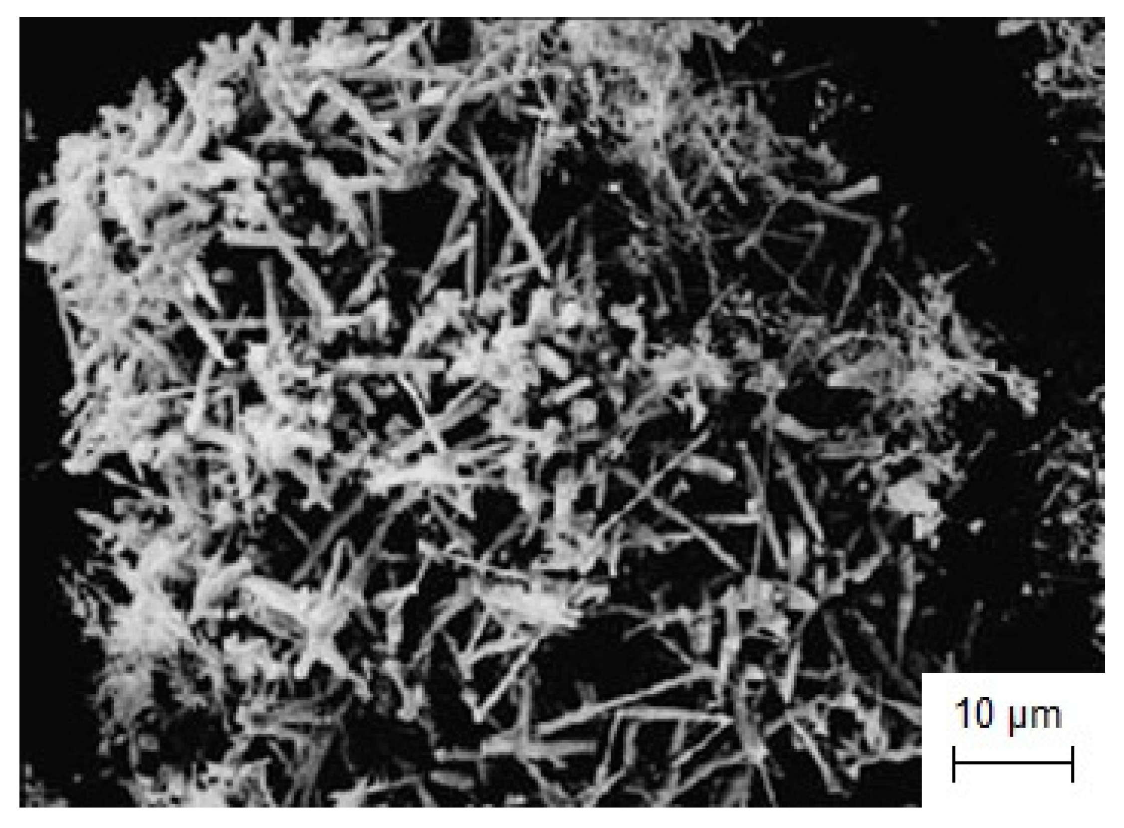
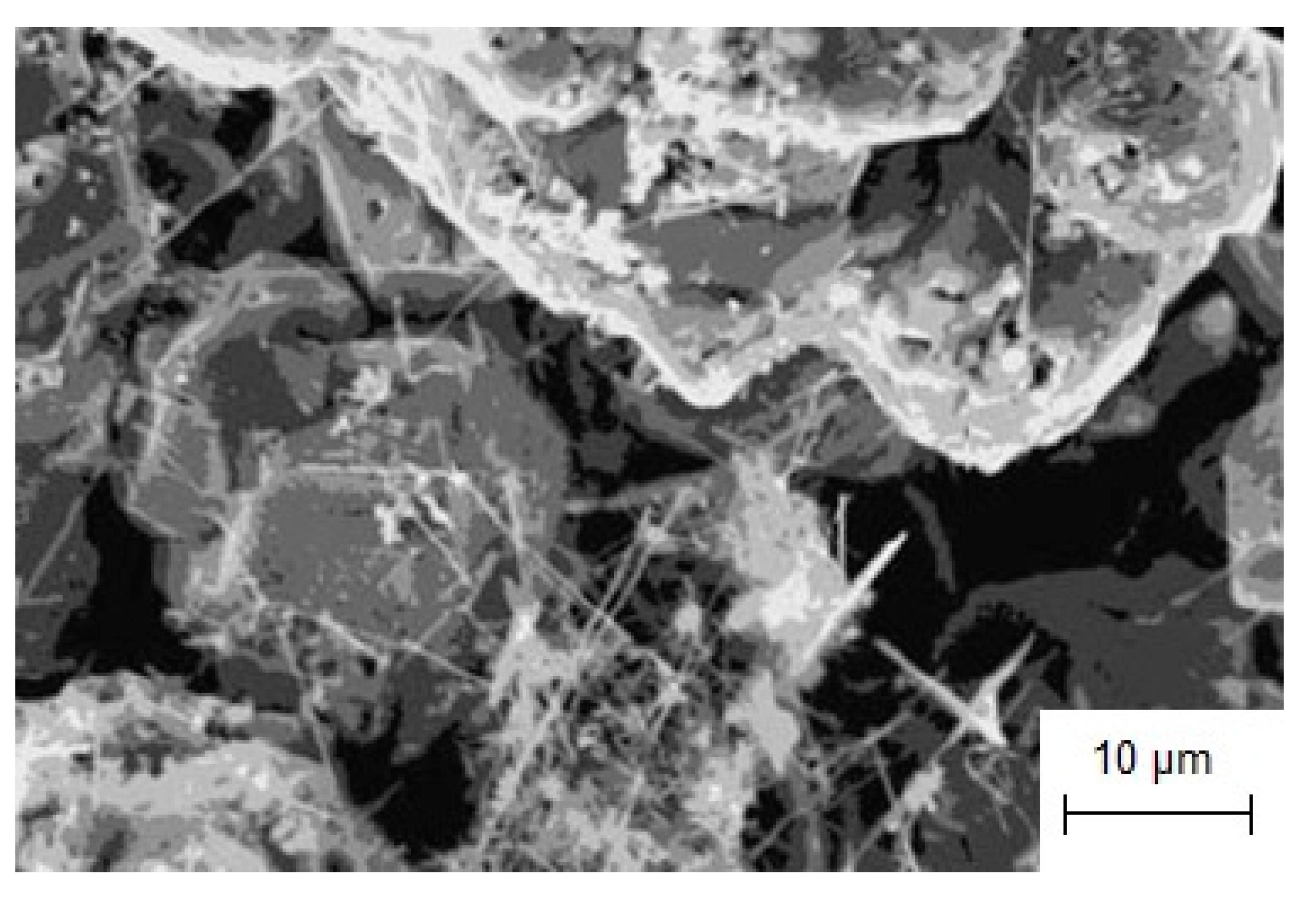
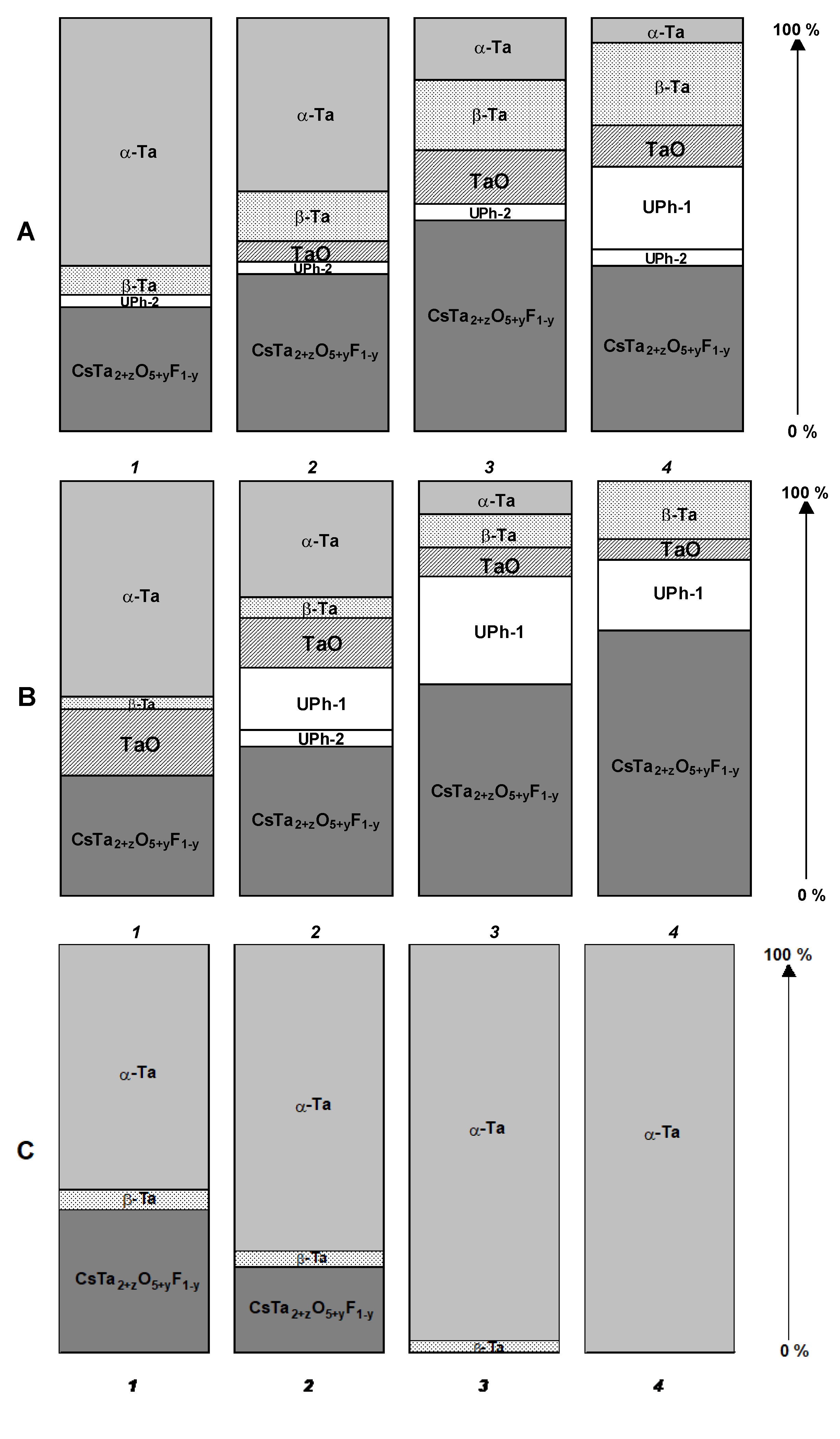
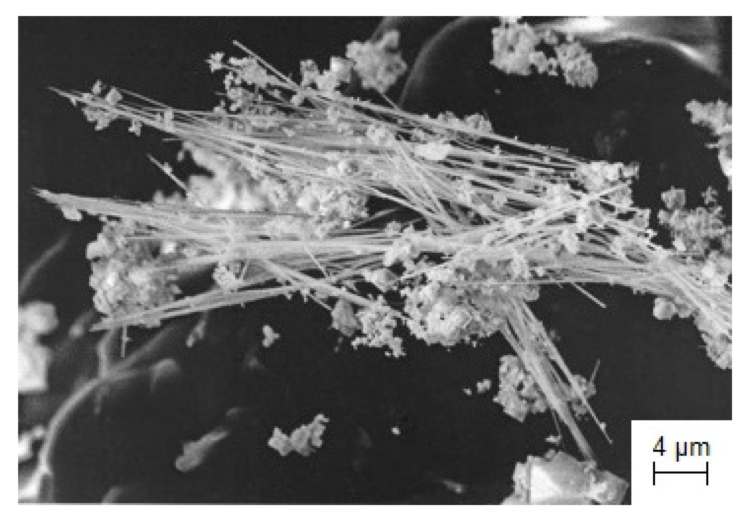
3.5.2. Obtaining of TaO Nanoneedles by Electroreduction of K3TaOF6 in Molten Salts

Tantalum monoxide can replace the tantalum pentoxide in high-density electric capacitors because of its high dielectric constant and low leakage current [117]. This material has been commercially integrated in capacitors which are used in computer dynamic random-access memory [118].
The formation of TaO was mentioned in several papers [119,120,121,122,123], but in [122,123] the electrocrystallization of tantalum monoxide was not confirmed by XRD analysis.
It was determined that during electroreduction of tantalum monoxofluoride complexes in the CsCl-K3TaOF6 melt, several phases containing tantalum are formed. The variation of cathodic products obtained at different parameters of electrolysis are presented in Figure 19. As can be seen from the diagrams in Figure 19, tantalum monoxide crystallized at the cathode with other tantalum compounds and did not form at a temperature of 1173 K. The micrograph of tantalum monoxide formed during electrolysis of the CsCl-K3TaOF6 melt is shown in Figure 20. It demonstrates that tantalum monoxide crystallizes at the cathode as nanoneedles up to 12,000 nm in length with a cross-section of ~100 nm.
Table 1 presents a brief summary of all functional coatings and nanomaterials considered in the present paper, the corresponding synthesis conditions in molten salts, and possible applications.

4. Conclusions

The advantages of high-temperature electrochemical synthesis of nanostructured coatings and various nanomaterials in molten salts were demonstrated:
  • By electrochemical synthesis in molten salts, a new Mo2C/Mo-based catalytic system for a low-temperature steam reforming reaction was obtained. The catalytic activity of this composition, produced by the simultaneous reduction of electroactive MoO42− and CO32− species, was three orders of magnitude higher than that of the bulk Mo2C phase and commercial Cu-ZnO-Al2O3 catalyst.
  • The currentless transfer for the synthesis of nanoscale coatings of carbide refractory metals on substrates containing carbon was studied. It was shown that these coatings on steels increase corrosion resistance by several orders of magnitude and increase wear resistance by 3–5 times. Tests carried out by industrial facilities showed that the coatings of Cr7C3 or TaC on rubber-cutting knifes made of St3 can improve their wear resistance and increase a tool lifetime by 2.0 (for Cr7C3) and 2.5 (for TaC) times.
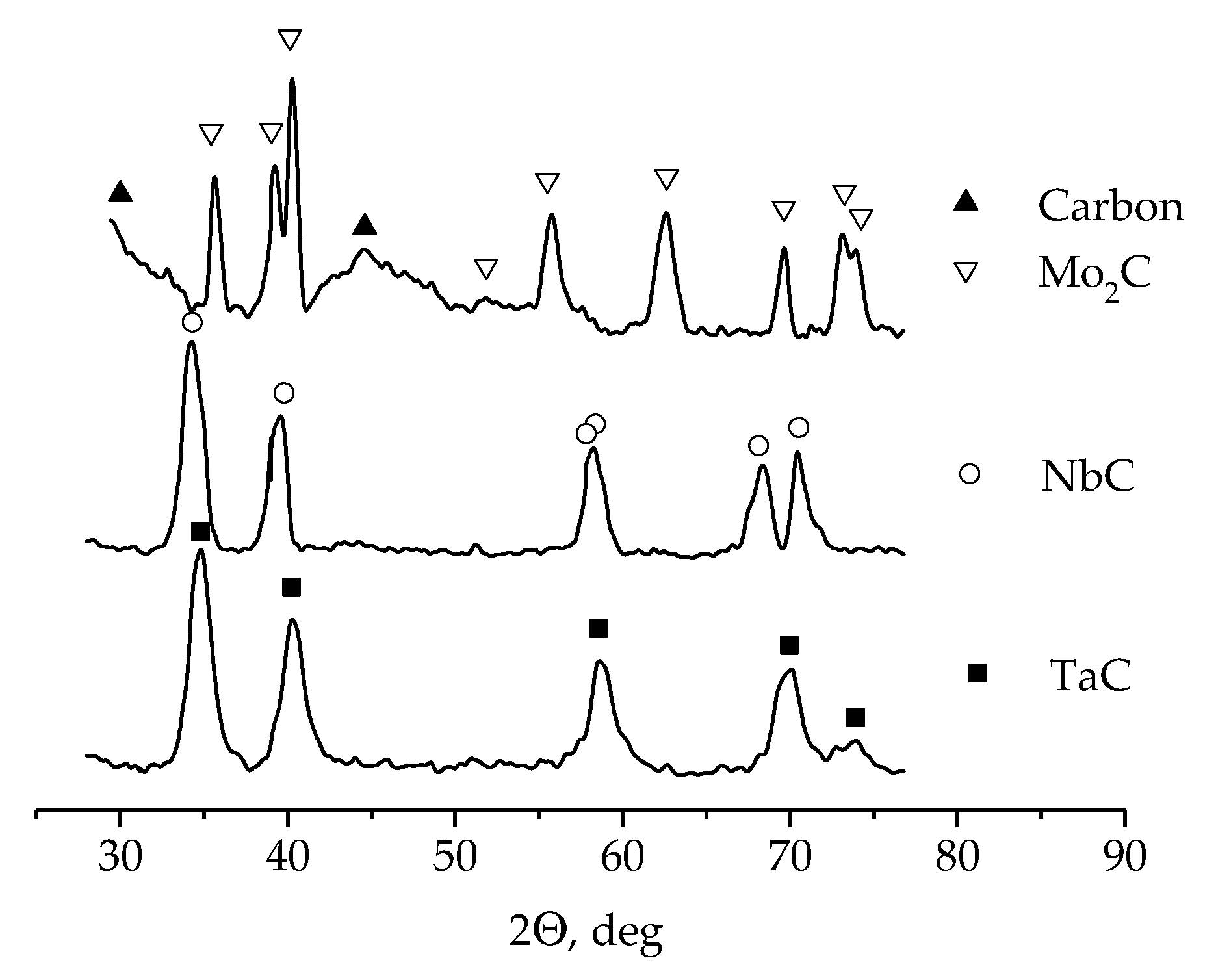
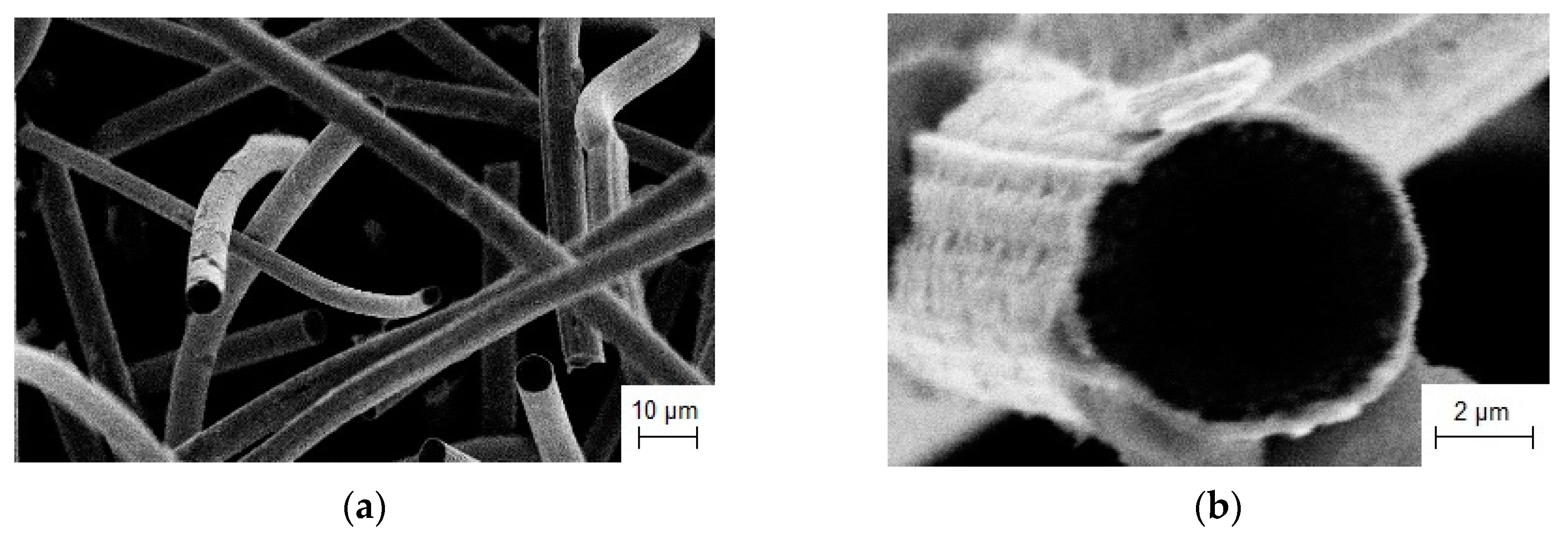
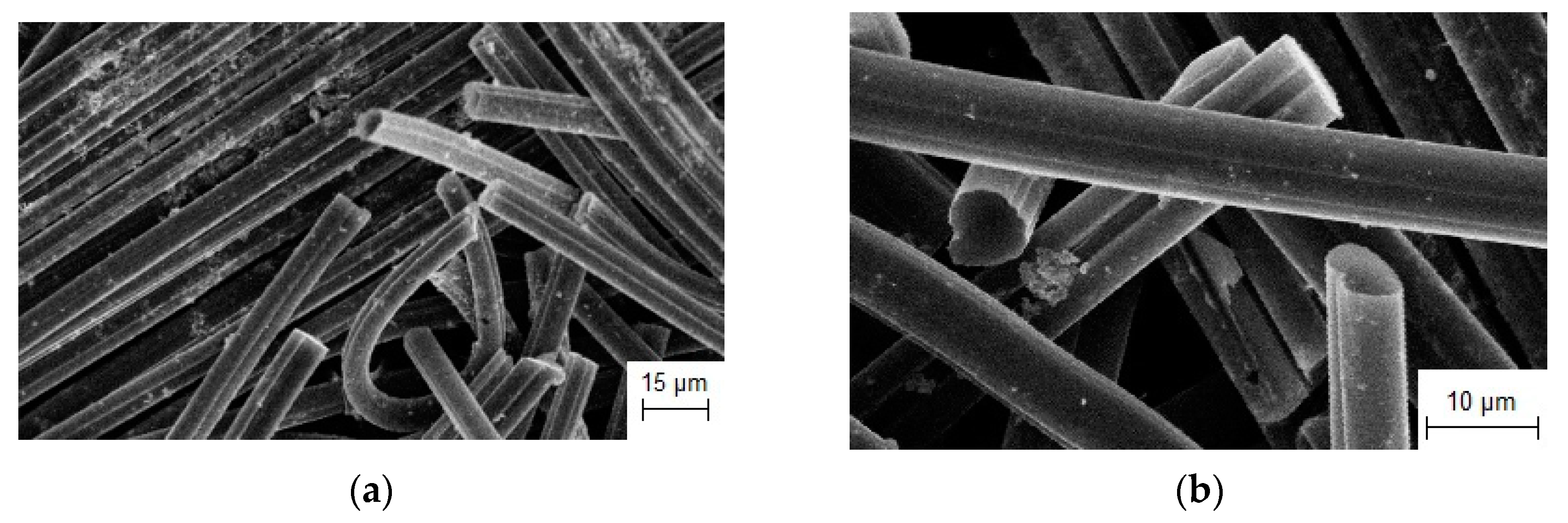
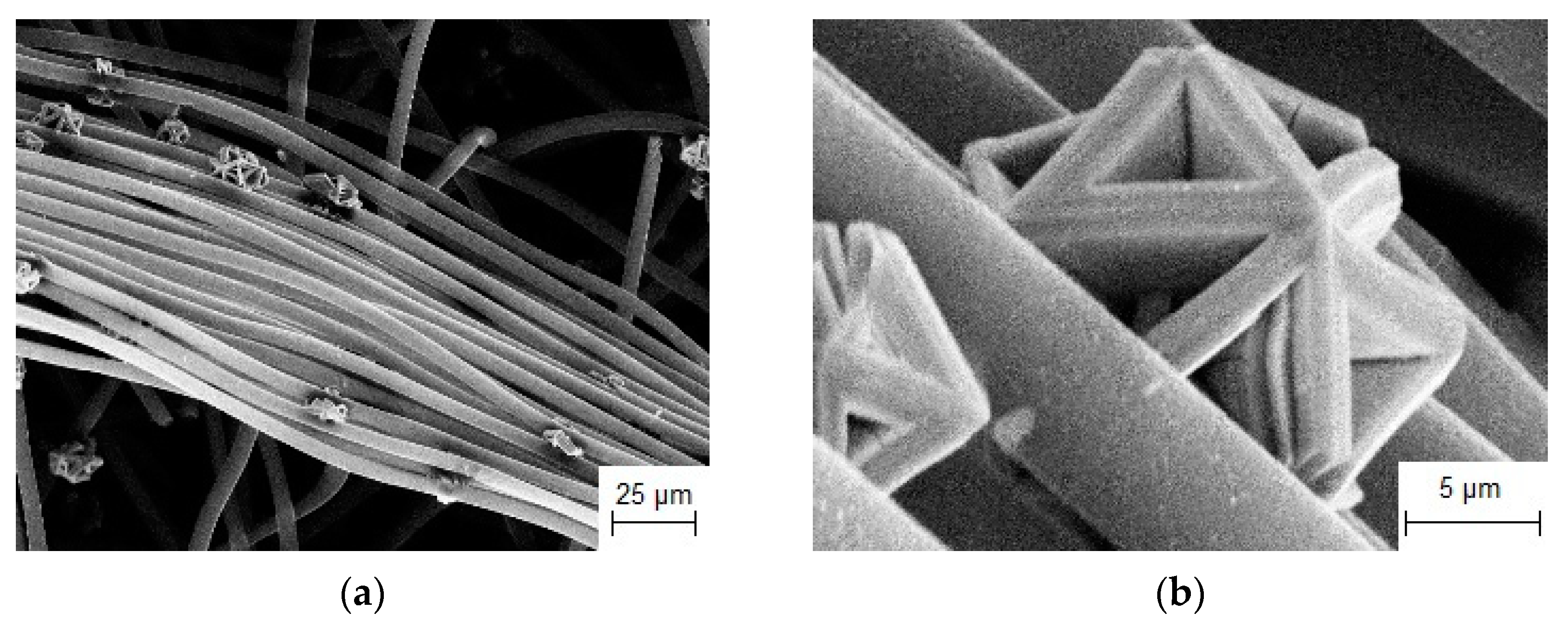
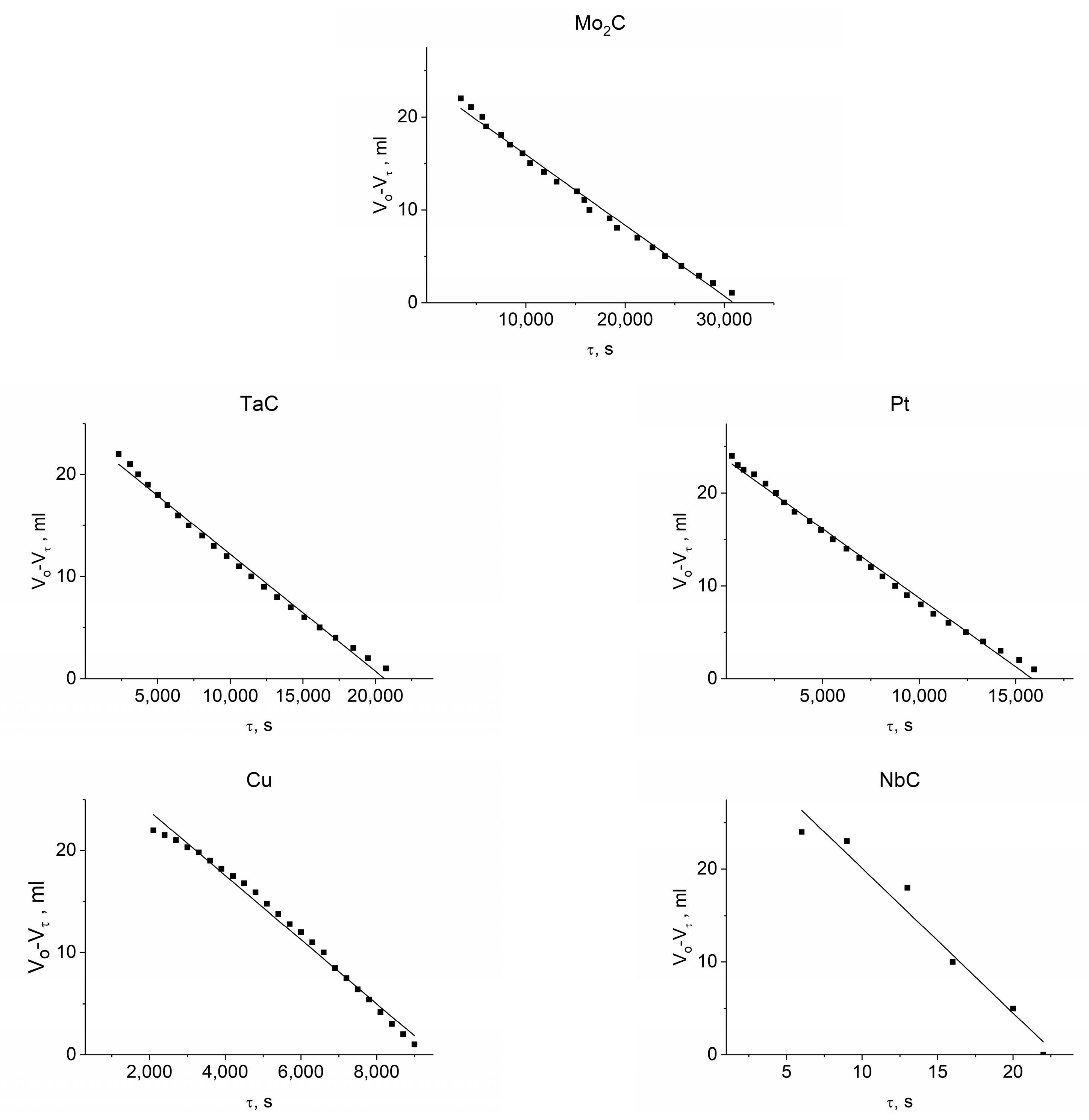
  • It was found that NbC, TaC, and Mo2C carbides deposited on carbon fibers by currentless transfer in molten salts can be used as highly active electrocatalysts for hydrogen peroxide decomposition. The kinetics of the electrocatalytic decomposition of H2O2 were studied and the following series of electrocatalytic activity was established: Mo2C < TaC < Pt < Cu < NbC.
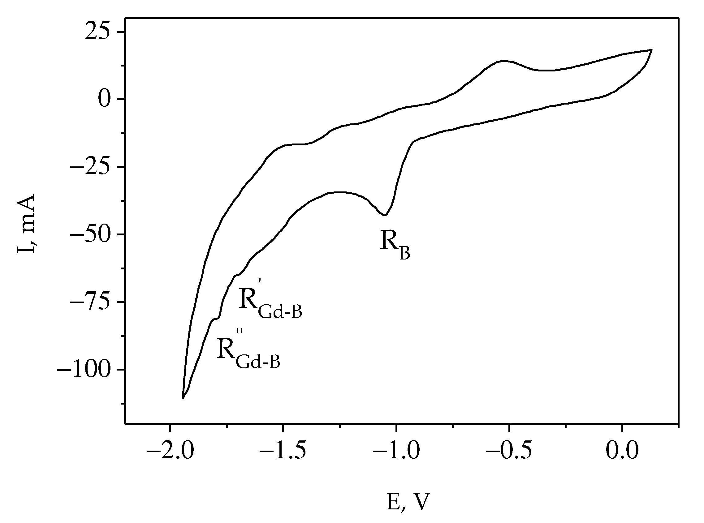
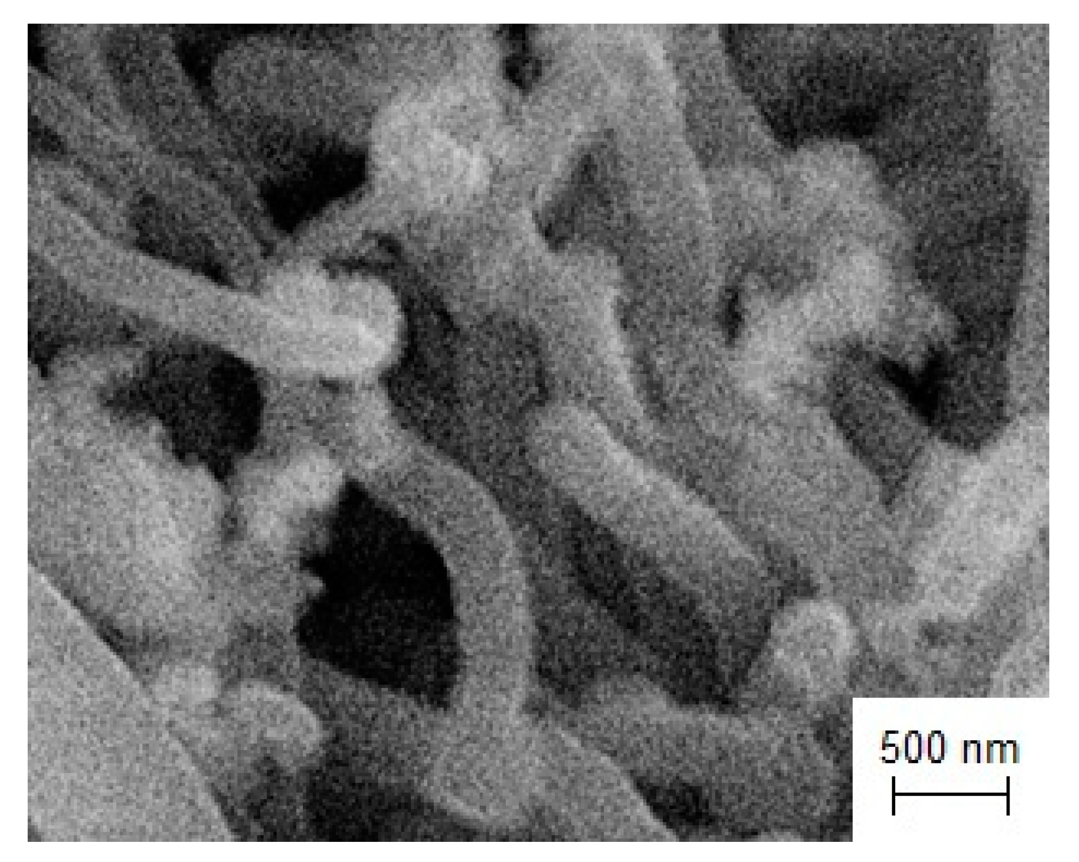
  • Using potentiostatic electrolysis, GdB6 nanorods for different applications were synthesized in the KCl-NaCl-NaF(10 wt.%)-GdF3-KBF4 melt.
  • The synthesis of one-dimensional nanomaterials based on Si and TaO for application in modern electronic devices was discussed. Silicon nanoneedles were synthesized by potentiostatic electrolysis in the NaCl–KCl–NaF(10 wt.%)-K2SiF6 melt. The possibility to synthesize TaO using the CsCl-K3TaOF6 melt was shown. TaO crystallized at the cathode as nanoneedles, together with other tantalum compounds. It was found that TaO can be obtained by the electrolysis of molten salts only at temperatures below 1173 K.

Author Contributions

Investigation, Y.S., V.D. and A.D.; Supervision, S.K.; Visualization, Y.S., V.D. and A.D.; Writing–original draft, Y.S., V.D. and A.D.; Writing–review and editing, S.K. All authors have read and agreed to the published version of the manuscript.

Funding

This research received no external funding.

Institutional Review Board Statement

Not applicable.

Informed Consent Statement

Not applicable.

Data Availability Statement

The data presented in this study are available on request from the corresponding author.

Conflicts of Interest

The authors declare no conflict of interest.

References

  1. Gleiter, H. Nanostructured Materials: Basic Concepts and Microstructure. Acta Mater. 2000, 48, 1–29. [Google Scholar] [CrossRef]
  2. Nazar, L.F.; Goward, G.; Leroux, F.; Duncan, M.; Huang, H.; Kerr, T.; Gaubicher, J. Nanostructured Materials for Energy Storage. Int. J. Inorg. Mater. 2001, 3, 191–200. [Google Scholar] [CrossRef]
  3. Hone, F.G.; Tegegne, N.A.; Andoshe, D.M. Advanced Materials for Energy Storage Devices. In Electrode Materials for Energy Storage and Conversion; CRC Press: Boca Raton, FL, USA, 2021; pp. 71–107. [Google Scholar] [CrossRef]
  4. Kebede, M.A.; Ezema, F.I. Electrode Materials for Energy Storage and Conversion. In Electrode Materials for Energy Storage and Conversion; CRC Press: Boca Raton, FL, USA, 2021. [Google Scholar] [CrossRef]
  5. Aoki, Y.; Tominaga, H.; Nagai, M. Hydrogenation of CO on Molybdenum and Cobalt Molybdenum Carbide Catalysts—Mass and Infrared Spectroscopy Studies. Catal. Today 2013, 215, 169–175. [Google Scholar] [CrossRef]
  6. Ren, H.; Yu, W.; Salciccioli, M.; Chen, Y.; Huang, Y.; Xiong, K.; Vlachos, D.G.; Chen, J.G. Selective Hydrodeoxygenation of Biomass-Derived Oxygenates to Unsaturated Hydrocarbons Using Molybdenum Carbide Catalysts. ChemSusChem 2013, 6, 798–801. [Google Scholar] [CrossRef] [PubMed]
  7. Schweitzer, N.M.; Schaidle, J.A.; Ezekoye, O.K.; Pan, X.; Linic, S.; Thompson, L.T. High Activity Carbide Supported Catalysts for Water Gas Shift. J. Am. Chem. Soc. 2011, 133, 2378–2381. [Google Scholar] [CrossRef]
  8. Malyshev, V.; Uskova, N.; Shakhnin, D.; Lukashenko, T.; Antsibor, V.; Ustundag, Z. High-Temperature Electrochemical Synthesis of Nanostructured Coatings of Molybdenum (Tungsten)–Nickel (Cobalt) Alloys and Intermetallic Compounds. In Selected Proceedings of the 5th International Conference Nanotechnology and Nanomaterials; Springer: Berlin/Heidelberg, Germany, 2018; pp. 165–176. ISBN 9783319925660. [Google Scholar]
  9. Zhang, W.; Hu, Y.; Ma, L.; Zhu, G.; Wang, Y.; Xue, X.; Chen, R.; Yang, S.; Jin, Z. Progress and Perspective of Electrocatalytic CO2 Reduction for Renewable Carbonaceous Fuels and Chemicals. Adv. Sci. 2018, 5, 1700275. [Google Scholar] [CrossRef]
  10. Hanus, M.J.; Harris, A.T. Nanotechnology Innovations for the Construction Industry. Prog. Mater. Sci. 2013, 58, 1056–1102. [Google Scholar] [CrossRef]
  11. Zhai, W.; Srikanth, N.; Kong, L.B.; Zhou, K. Carbon Nanomaterials in Tribology. Carbon N. Y. 2017, 119, 150–171. [Google Scholar] [CrossRef]
  12. Pottathara, Y.B.; Thomas, S.; Kalarikkal, N.; Grohens, Y.; Kokol, V. Nanomaterials Synthesis; Elsevier: Amsterdam, The Netherlands, 2019; ISBN 9780128157510. [Google Scholar]
  13. Chen, X.; Mao, S.S. Titanium Dioxide Nanomaterials: Synthesis, Properties, Modifications and Applications. Chem. Rev. 2007, 107, 2891–2959. [Google Scholar] [CrossRef]
  14. Chen, J.S.; Lou, X.W. SnO2-Based Nanomaterials: Synthesis and Application in Lithium-Ion Batteries. Small 2013, 9, 1877–1893. [Google Scholar] [CrossRef]
  15. Kolahalam, L.A.; Kasi Viswanath, I.V.; Diwakar, B.S.; Govindh, B.; Reddy, V.; Murthy, Y.L.N. Review on Nanomaterials: Synthesis and Applications. Mater. Today Proc. 2019, 18, 2182–2190. [Google Scholar] [CrossRef]
  16. Sriondee, M.; Dungsuwan, W.; Thountom, S. Synthesis and Characterization of Bi0.5(Na1-XKx)0.5TiO3 Powders by Sol–Gel Combustion Method with Glycine Fuel. Ceram. Int. 2018, 44, S168–S171. [Google Scholar] [CrossRef]
  17. Hao, S.; Lin, T.; Ning, S.; Qi, Y.; Deng, Z.; Wang, Y. Research on Cracking of SiO2 Nanofilms Prepared by the Sol-Gel Method. Mater. Sci. Semicond. Process. 2019, 91, 181–187. [Google Scholar] [CrossRef]
  18. Kasi Viswanath, I.V.; Murthy, Y.L.N.; Tata, K.R.; Singh, R. Synthesis and Characterization of Nano Ferrites by Citrate Gel Method. Int. J. Chem. Sci. 2013, 11, 64–72. [Google Scholar]
  19. Ikesue, A.; Kinoshita, T.; Kamata, K.; Yoshida, K. Fabrication and Optical Properties of High-Performance Polycrystalline Nd:YAG Ceramics for Solid-State Lasers. J. Am. Ceram. Soc. 1995, 78, 1033–1040. [Google Scholar] [CrossRef]
  20. Yu, S.; Jing, W.; Tang, M.; Xu, T.; Yin, W.; Kang, B. Fabrication of Nd:YAG Transparent Ceramics Using Powders Synthesized by Citrate Sol-Gel Method. J. Alloys Compd. 2019, 772, 751–759. [Google Scholar] [CrossRef]
  21. Holland, B.T.; Blanford, C.F.; Do, T.; Stein, A. Synthesis of Highly Ordered, Three-Dimensional, Macroporous Structures of Amorphous or Crystalline Inorganic Oxides, Phosphates, and Hybrid Composites. Chem. Mater. 1999, 11, 795–805. [Google Scholar] [CrossRef]
  22. Diwald, O.; Thompson, T.L.; Zubkov, T.; Goralski, E.G.; Walck, S.D.; Yates, J.T. Photochemical Activity of Nitrogen-Doped Rutile TiO2(110) in Visible Light. J. Phys. Chem. B 2004, 108, 6004–6008. [Google Scholar] [CrossRef]
  23. Sasaki, T.; Watanabe, M.; Hashizume, H.; Yamada, H.; Nakazawa, H. Macromolecule-like Aspects for a Colloidal Suspension of an Exfoliated Titanate. Pairwise Association of Nanosheets and Dynamic Reassembling Process Initiated from It. J. Am. Chem. Soc. 1996, 118, 8329–8335. [Google Scholar] [CrossRef]
  24. Schlüter, M.; Hentzel, T.; Suarez, C.; Koch, M.; Lorenz, W.G.; Böhm, L.; Düring, R.A.; Koinig, K.A.; Bunge, M. Synthesis of Novel Palladium(0) Nanocatalysts by Microorganisms from Heavy-Metal-Influenced High-Alpine Sites for Dehalogenation of Polychlorinated Dioxins. Chemosphere 2014, 117, 462–470. [Google Scholar] [CrossRef]
  25. Anderson, S.H.; Chung, D.D.L. Exfoliation of Single Crystal Graphite and Graphite Fibers Intercalated with Halogens. Synth. Met. 1983, 8, 343–349. [Google Scholar] [CrossRef]
  26. Sharma, N.; Sharma, V.; Sharma, S.K.; Sachdev, K. Gas Sensing Behaviour of Green Synthesized Reduced Graphene Oxide (RGO) for H2 and NO. Mater. Lett. 2019, 236, 444–447. [Google Scholar] [CrossRef]
  27. Kadam, R.H.; Desai, K.; Shinde, V.S.; Hashim, M.; Shirsath, S.E. Influence of Gd3+ Ion Substitution on the MnCrFeO4 for Their Nanoparticle Shape Formation and Magnetic Properties. J. Alloys Compd. 2016, 657, 487–494. [Google Scholar] [CrossRef]
  28. Shi, Y.; Li, H.; Li, L.J. Recent Advances in Controlled Synthesis of Two-Dimensional Transition Metal Dichalcogenides via Vapour Deposition Techniques. Chem. Soc. Rev. 2015, 44, 2744–2756. [Google Scholar] [CrossRef] [PubMed]
  29. Ismach, A.; Druzgalski, C.; Penwell, S.; Schwartzberg, A.; Zheng, M.; Javey, A.; Bokor, J.; Zhang, Y. Direct Chemical Vapor Deposition of Graphene on Dielectric Surfaces. Nano Lett. 2010, 10, 1542–1548. [Google Scholar] [CrossRef]
  30. Kim, K.K.; Hsu, A.; Jia, X.; Kim, S.M.; Shi, Y.; Hofmann, M.; Nezich, D.; Rodriguez-Nieva, J.F.; Dresselhaus, M.; Palacios, T.; et al. Synthesis of Monolayer Hexagonal Boron Nitride on Cu Foil Using Chemical Vapor Deposition. Nano Lett. 2012, 12, 161–166. [Google Scholar] [CrossRef]
  31. Saito, T.; Chiba, H.; Ito, T.; Ogino, T. Growth of Carbon Hybrid Materials by Grafting on Pre-Grown Carbon Nanotube Surfaces. Carbon N. Y. 2010, 48, 1305–1311. [Google Scholar] [CrossRef]
  32. Xie, W.; Pang, Z.; Fan, J.; Song, H.; Jiang, F.; Yuan, H.; Li, J.; Ji, Z.; Han, S. Structural Properties of Alq3 Nanocrystals Prepared by Physical Vapor Deposition and Facile Solution Method. Int. J. Mod. Phys. B 2015, 29, 1542042. [Google Scholar] [CrossRef]
  33. Maleki, A. Green Oxidation Protocol: Selective Conversions of Alcohols and Alkenes to Aldehydes, Ketones and Epoxides by Using a New Multiwall Carbon Nanotube-Based Hybrid Nanocatalyst via Ultrasound Irradiation. Ultrason. Sonochem. 2018, 40, 460–464. [Google Scholar] [CrossRef]
  34. Xu, H.; Suslick, K.S. Sonochemical Synthesis of Highly Fluorescent Ag Nanoclusters. ACS Nano 2010, 4, 3209–3214. [Google Scholar] [CrossRef] [PubMed]
  35. Morel, A.L.; Nikitenko, S.I.; Gionnet, K.; Wattiaux, A.; Lai-Kee-Him, J.; Labrugere, C.; Chevalier, B.; Deleris, G.; Petibois, C.; Brisson, A.; et al. Sonochemical Approach to the Synthesis of Fe3O4 @SiO2 Core—Shell Nanoparticles with Tunable Properties. ACS Nano 2008, 2, 847–856. [Google Scholar] [CrossRef]
  36. Gedanken, A. Using Sonochemistry for the Fabrication of Nanomaterials. Ultrason. Sonochem. 2004, 11, 47–55. [Google Scholar] [CrossRef]
  37. Bang, J.H.; Suslick, K.S. Applications of Ultrasound to the Synthesis of Nanostructured Materials. Adv. Mater. 2010, 22, 1039–1059. [Google Scholar] [CrossRef]
  38. Zuo, P.; Lu, X.; Sun, Z.; Guo, Y.; He, H. A Review on Syntheses, Properties, Characterization and Bioanalytical Applications of Fluorescent Carbon Dots. Microchim. Acta 2016, 183, 519–542. [Google Scholar] [CrossRef]
  39. Gawande, M.B.; Shelke, S.N.; Zboril, R.; Varma, R.S. Microwave-Assisted Chemistry: Synthetic Applications for Rapid Assembly of Nanomaterials and Organics. Acc. Chem. Res. 2014, 47, 1338–1348. [Google Scholar] [CrossRef] [PubMed]
  40. Baghbanzadeh, M.; Carbone, L.; Cozzoli, P.D.; Kappe, C.O. Microwave-Assisted Synthesis of Colloidal Inorganic Nanocrystals. Angew. Chem.-Int. Ed. 2011, 50, 11312–11359. [Google Scholar] [CrossRef]
  41. Bilecka, I.; Niederberger, M. Microwave Chemistry for Inorganic Nanomaterials Synthesis. Nanoscale 2010, 2, 1358–1374. [Google Scholar] [CrossRef] [PubMed]
  42. Ustarroz, J.; Hammons, J.A.; Altantzis, T.; Hubin, A.; Bals, S.; Terryn, H. A Generalized Electrochemical Aggregative Growth Mechanism. J. Am. Chem. Soc. 2013, 135, 11550–11561. [Google Scholar] [CrossRef]
  43. Yin, Y.; Jin, Z.; Hou, F. Enhanced Solar Water-Splitting Efficiency Using Core/Sheath Heterostructure CdS/TiO2 Nanotube Arrays. Nanotechnology 2007, 18, 495608. [Google Scholar] [CrossRef]
  44. Zhu, T.; Chong, M.N.; Chan, E.S. Nanostructured Tungsten Trioxide Thin Films Synthesized for Photoelectrocatalytic Water Oxidation: A Review. ChemSusChem 2014, 7, 2974–2997. [Google Scholar] [CrossRef] [PubMed]
  45. Mudring, A.V.; Tang, S. Ionic Liquids for Lanthanide and Actinide Chemistry. Eur. J. Inorg. Chem. 2010, 2010, 2569–2581. [Google Scholar] [CrossRef]
  46. Chou, S.; Cheng, F.; Chen, J. Electrodeposition Synthesis and Electrochemical Properties of Nanostructured γ-MnO2 Films. J. Power Sources 2006, 162, 727–734. [Google Scholar] [CrossRef]
  47. Logeeswaran, V.J.; Kobayashi, N.P.; Islam, M.S.; Wu, W.; Chaturvedi, P.; Fang, N.X.; Wang, S.Y.; Williams, R.S. Ultrasmooth Silver Thin Films Deposited with a Germanium Nucleation Layer. Nano Lett. 2009, 9, 178–182. [Google Scholar] [CrossRef] [PubMed]
  48. Tepavcevic, S.; Xiong, H.; Stamenkovic, V.R.; Zuo, X.; Balasubramanian, M.; Prakapenka, V.B.; Johnson, C.S.; Rajh, T. Nanostructured Bilayered Vanadium Oxide Electrodes for Rechargeable Sodium-Ion Batteries. ACS Nano 2012, 6, 530–538. [Google Scholar] [CrossRef]
  49. Abo-Hamad, A.; Hayyan, M.; AlSaadi, M.A.H.; Hashim, M.A. Potential Applications of Deep Eutectic Solvents in Nanotechnology. Chem. Eng. J. 2015, 273, 551–567. [Google Scholar] [CrossRef]
  50. Shiddiky, M.J.A.; Torriero, A.A.J. Application of Ionic Liquids in Electrochemical Sensing Systems. Biosens. Bioelectron. 2011, 26, 1775–1787. [Google Scholar] [CrossRef] [PubMed]
  51. Eftekhari, A. Nanostructured Materials in Electrochemistry; Wiley: Hoboken, NJ, USA, 2008. [Google Scholar]
  52. Krishtalik, L.I. Electrode Reactions. Mechanism of Elementary Act; Nauka: Moscow, Russia, 1982. [Google Scholar]
  53. Islam, M.M.; Abdellaoui, I.; Moslah, C.; Sakurai, T.; Ksibi, M.; Hamzaoui, S.; Akimoto, K. Electrodeposition and Characterization of Silicon Films Obtained through Electrochemical Reduction of SiO2 Nanoparticles. Thin Solid Film. 2018, 654, 1–10. [Google Scholar] [CrossRef]
  54. Zou, X.; Ji, L.; Ge, J.; Sadoway, D.R.; Yu, E.T.; Bard, A.J. Electrodeposition of Crystalline Silicon Films from Silicon Dioxide for Low-Cost Photovoltaic Applications. Nat. Commun. 2019, 10, 5772. [Google Scholar] [CrossRef]
  55. Weng, W.; Xiao, W. Electrodeposited Silicon Nanowires from Silica Dissolved in Molten Salts as a Binder-Free Anode for Lithium-Ion Batteries. ACS Appl. Energy Mater. 2019, 2, 804–813. [Google Scholar] [CrossRef]
  56. Laptev, M.V.; Isakov, A.V.; Grishenkova, O.V.; Vorob’ev, A.S.; Khudorozhkova, A.O.; Akashev, L.A.; Zaikov, Y.P. Electrodeposition of Thin Silicon Films from the KF-KCl-KI-K2SiF6 Melt. J. Electrochem. Soc. 2020, 167, 042506. [Google Scholar] [CrossRef]
  57. Zou, X.; Ji, L.; Pang, Z.; Xu, Q.; Lu, X. Continuous Electrodeposition of Silicon and Germanium Micro⁄nanowires from Their Oxides Precursors in Molten Salt. J. Energy Chem. 2020, 44, 147–153. [Google Scholar] [CrossRef]
  58. Yasko, O.; Shakhnin, D.B.; Gab, A.; Malyshev, V.; Gaune-Escard, M. Electrodeposition of Nanostructured Silicon Coatings onto Different Materials from Halide and Halide–Oxide Melts. In Springer Proceedings in Physics; Springer Science and Business Media Deutschland GmbH: Berlin, Germany, 2021; Volume 246, pp. 231–235. ISBN 9783030519049. [Google Scholar]
  59. Gevel, T.; Zhuk, S.; Leonova, N.; Leonova, A.; Trofimov, A.; Suzdaltsev, A.; Zaikov, Y. Electrochemical Synthesis of Nano-Sized Silicon from KCl–K2SiF6 Melts for Powerful Lithium-Ion Batteries. Appl. Sci. 2021, 11, 10927. [Google Scholar] [CrossRef]
  60. Wang, F.; Ma, Y.; Li, P.; Peng, C.; Yin, H.; Li, W.; Wang, D. Electrochemical Conversion of Silica Nanoparticles to Silicon Nanotubes in Molten Salts: Implications for High-Performance Lithium-Ion Battery Anode. ACS Appl. Nano Mater. 2021, 4, 7028–7036. [Google Scholar] [CrossRef]
  61. Jing, S.; Xiao, J.; Shen, Y.; Hong, B.; Gu, D.; Xiao, W. Silicate-Mediated Electrolytic Silicon Nanotube from Silica in Molten Salts. Small 2022, 18, 2203251. [Google Scholar] [CrossRef]
  62. Rezaei, A.; Kamali, A.R. Green Production of Carbon Nanomaterials in Molten Salts, Mechanisms and Applications. Diam. Relat. Mater. 2018, 83, 146–161. [Google Scholar] [CrossRef]
  63. Hu, L.; Song, Y.; Ge, J.; Zhu, J.; Jiao, S. Capture and Electrochemical Conversion of CO2 to Ultrathin Graphite Sheets in CaCl2-Based Melts. J. Mater. Chem. A 2015, 3, 21211–21218. [Google Scholar] [CrossRef]
  64. Wu, H.; Li, Z.; Ji, D.; Liu, Y.; Li, L.; Yuan, D.; Zhang, Z.; Ren, J.; Lefler, M.; Wang, B.; et al. One-Pot Synthesis of Nanostructured Carbon Materials from Carbon Dioxide via Electrolysis in Molten Carbonate Salts. Carbon N. Y. 2016, 106, 208–217. [Google Scholar] [CrossRef]
  65. Novoselova, I.A.; Oliynyk, N.F.; Volkov, S.V. Electrolytic Production of Carbon Nano-Tubes in Chloride-Oxide Melts under Carbon Dioxide Pressure. In Hydrogen Materials Science and Chemistry of Carbon Nanomaterials; Springer: Dordrecht, The Netherlands, 2007; pp. 459–465. ISBN 1402055129. [Google Scholar]
  66. Ijije, H.V.; Lawrence, R.C.; Chen, G.Z. Carbon Electrodeposition in Molten Salts: Electrode Reactions and Applications. RSC Adv. 2014, 4, 35808–35817. [Google Scholar] [CrossRef]
  67. Mao, X.; Yan, Z.; Sheng, T.; Gao, M.; Zhu, H.; Xiao, W.; Wang, D. Characterization and Adsorption Properties of the Electrolytic Carbon Derived from CO2 Conversion in Molten Salts. Carbon N. Y. 2017, 111, 162–172. [Google Scholar] [CrossRef]
  68. Kushkhov, K.B.; Ligidova, M.N.; Ali, J.Z.; Khotov, A.A.; Tlenkopachev, M.R.; Karatsukova, R.K. Electrochemical Processes in Molten Alkaline Metal Carbonates under Carbon Dioxide Overpressure. Russ. Metall. 2021, 2021, 141–150. [Google Scholar] [CrossRef]
  69. Wang, M.; Kim, Y.; Zhang, L.; Seong, W.K.; Kim, M.; Chatterjee, S.; Wang, M.; Li, Y.; Bakharev, P.V.; Lee, G.; et al. Controllable Electrodeposition of Ordered Carbon Nanowalls on Cu(111) Substrates. Mater. Today 2022, 57, 75–83. [Google Scholar] [CrossRef]
  70. Kumar, K.; Mondal, S. Fabrication and Characterisation of Carbon Nanotube Reinforced Copper Matrix Nanocomposites. Can. Metall. Q. 2022, 61, 77–84. [Google Scholar] [CrossRef]
  71. Groult, H.; Le Van, K.; Lantelme, F. Electrodeposition of Carbon-Metal Powders in Alkali Carbonate Melts. J. Electrochem. Soc. 2014, 161, D3130–D3138. [Google Scholar] [CrossRef]
  72. Hu, L.; Song, Y.; Ge, J.; Zhu, J.; Han, Z.; Jiao, S. Electrochemical Deposition of Carbon Nanotubes from CO2 in CaCl2 –NaCl-Based Melts. J. Mater. Chem. A 2017, 5, 6219–6225. [Google Scholar] [CrossRef]
  73. Xu, Q.; Schwandt, C.; Chen, G.Z.; Fray, D.J. Electrochemical Investigation of Lithium Intercalation into Graphite from Molten Lithium Chloride. J. Electroanal. Chem. 2002, 530, 16–22. [Google Scholar] [CrossRef]
  74. Kamali, A.R. Nanocatalytic Conversion of CO2 into Nanodiamonds. Carbon N. Y. 2017, 123, 205–215. [Google Scholar] [CrossRef]
  75. Yasko, O.; Malyshev, V.; Gab, A.; Lukashenko, T. Joint Electroreduction of Carbonate and Tungstate Ions as the Base for Tungsten Carbide Nanopowders Synthesis in Ionic Melts. In Springer Proceedings in Physics; Springer Science and Business Media, LLC: Berlin, Germany, 2019; Volume 221, pp. 397–402. ISBN 9783030177584. [Google Scholar]
  76. Malyshev, V.; Gab, A.; Shakhnin, D.; Lukashenko, T.; Ishtvanik, O.; Gaune-Escard, M. High-Temperature Electrochemical Synthesis of Nanopowders of Tungsten Carbide in Ionic Melts. In Springer Proceedings in Physics; Springer Science and Business Media, LLC: Berlin, Germany, 2018; Volume 214, pp. 311–321. ISBN 9783319925660. [Google Scholar]
  77. Kushkhov, K.B.; Kardanov, A.L.; Adamokova, M.N. Electrochemical Synthesis of Binary Molybdenum-Tungsten Carbides (Mo,W)2C from Tungstate-Molybdate-Carbonate Melts. Russ. Metall. 2013, 2013, 79–85. [Google Scholar] [CrossRef]
  78. Bukatova, G.A.; Kuznetsov, S.A. Electrosynthesis of Gadolinium Hexaboride Nanotubes. Electrochem. Commun. 2005, 7, 637–641. [Google Scholar] [CrossRef]
  79. Kuznetsov, S.A.; Kremenetsky, V.G.; Popova, A.V.; Kremenetskaya, O.V.; Kalinnikov, V.T. Unusual Effect of the Second Coordination Sphere on the Standard Charge Transfer Rate Constants for the Nb(V)/Nb(IV) Redox Couple in Chloride—Fluoride Melts. Dokl. Phys. Chem. 2009, 428, 209–212. [Google Scholar] [CrossRef]
  80. Grinevitch, V.V.; Kuznetsov, S.A.; Arakcheeva, A.A.; Olyunina, T.V.; Schønleber, A.; Gaune-Escard, M. Electrode and Chemical Reactions during Electrodeposition of Tantalum Products in CsCl Melt. Electrochim. Acta 2006, 51, 6563–6571. [Google Scholar] [CrossRef]
  81. Kuznetsov, S.A.; Rebrov, E.V.; Mies, M.J.M.; de Croon, M.H.J.M.; Schouten, J.C. Synthesis of Protective Mo–Si–B Coatings in Molten Salts and Their Oxidation Behavior in an Air–Water Mixture. Surf. Coat. Technol. 2006, 201, 971–978. [Google Scholar] [CrossRef]
  82. Grinevitch, V.V.; Arakcheeva, A.V.; Kuznetsov, S.A. Tantalum Metal of Peculiar Cristal Lattice (b-Ta) as Creation of Elec-Trocrystallization from Molten Salts. In International Symposium on Ionic Liquids; DTU Research Database: Carry le Rouet, France, 2003; pp. 277–285. [Google Scholar]
  83. Dubrovskiy, A.R.; Makarova, O.V.; Kuznetsov, S.A. Effect of the Molybdenum Substrate Shape on Mo2C Coating Electrodeposition. Coatings 2018, 8, 442. [Google Scholar] [CrossRef]
  84. Dubrovskii, A.R.; Kuznetsov, S.A.; Rebrov, E.V.; Schouten, J.C. Catalytic Coatings of New Generation Based on Mo2C and a Microstructured Reactor for Steam Conversion of Carbon Monoxide. Russ. J. Appl. Chem. 2014, 87, 601–607. [Google Scholar] [CrossRef]
  85. Dubrovskiy, A.R.; Okunev, M.A.; Makarova, O.V.; Kuznetsov, S.A. Superconducting Niobium Coatings Deposited on Spherical Substrates in Molten Salts. Coatings 2018, 8, 213. [Google Scholar] [CrossRef]
  86. Patt, J.; Moon, D.J.; Phillips, C.; Thompson, L. Molybdenum Carbide Catalysts for Water-Gas Shift. Catal. Lett. 2000, 65, 193–195. [Google Scholar] [CrossRef]
  87. Derakhshandeh, M.R.; Eshraghi, M.J.; Razavi, M. Recent Developments in the New Generation of Hard Coatings Applied on Cemented Carbide Cutting Tools. Int. J. Refract. Met. Hard Mater. 2023, 111, 106077. [Google Scholar] [CrossRef]
  88. Lee, C.; Danon, Y.; Mulligan, C. Characterization of Niobium, Tantalum and Chromium Sputtered Coatings on Steel Using Eddy Currents. Surf. Coat. Technol. 2005, 200, 2547–2556. [Google Scholar] [CrossRef]
  89. Lee, Y.J.; Lee, T.H.; Kim, D.Y.; Nersisyan, H.H.; Han, M.H.; Kang, K.S.; Bae, K.K.; Shin, Y.J.; Lee, J.H. Microstructural and Corrosion Characteristics of Tantalum Coatings Prepared by Molten Salt Electrodeposition. Surf. Coat. Technol. 2013, 235, 819–826. [Google Scholar] [CrossRef]
  90. Emsley, J. Nature’s Building Blocks: An A-Z Guide to the Elements; Oxford University Press: Oxford, UK, 2003. [Google Scholar]
  91. Baklanova, N.I.; Zima, T.M.; Boronin, A.I.; Kosheev, S.V.; Titov, A.T.; Isaeva, N.V.; Graschenkov, D.V.; Solntsev, S.S. Protective Ceramic Multilayer Coatings for Carbon Fibers. Surf. Coat. Technol. 2006, 201, 2313–2319. [Google Scholar] [CrossRef]
  92. Wang, S.-C.; Lin, H.-T.; Nayak, P.K.; Chang, S.-Y.; Huang, J.-L. Carbothermal Reduction Process for Synthesis of Nanosized Chromium Carbide via Metal-Organic Vapor Deposition. Thin Solid Film. 2010, 518, 7360–7365. [Google Scholar] [CrossRef]
  93. Sen, S. Influence of Chromium Carbide Coating on Tribological Performance of Steel. Mater. Des. 2006, 27, 85–91. [Google Scholar] [CrossRef]
  94. Gómez, M.A.; Romero, J.; Lousa, A.; Esteve, J. Tribological Performance of Chromium/Chromium Carbide Multilayers Deposited by r.f. Magnetron Sputtering. Surf. Coat. Technol. 2005, 200, 1819–1824. [Google Scholar] [CrossRef]
  95. Cintho, O.M.; Favilla, E.A.P.; Capocchi, J.D.T. Mechanical–Thermal Synthesis of Chromium Carbides. J. Alloys Compd. 2007, 439, 189–195. [Google Scholar] [CrossRef]
  96. Esteve, J.; Romero, J.; Gómez, M.; Lousa, A. Cathodic Chromium Carbide Coatings for Molding Die Applications. Surf. Coat. Technol. 2004, 188–189, 506–510. [Google Scholar] [CrossRef]
  97. Shatinsky, V.D.; Nesterenko, F.I. Protecting Diffusional Coatings; Naukova Dumka: Kiev, Ukraine, 1988. [Google Scholar]
  98. Stulov, Y.V.; Kuznetsov, S.A. Synthesis of Chromium Carbide Coatings on Carbon Steels in Molten Salts and Their Properties. Glas. Phys. Chem. 2014, 40, 324–328. [Google Scholar] [CrossRef]
  99. Ilyushchenko, N.G.; Afinogenov, A.I.; Shurov, N.I. Metal Interactions in Ionic Melts; Nauka: Moscow, Russia, 1991. [Google Scholar]
  100. Novokreshchenov, Y.V.; Petenev, O.S.; Kositsyn, Y.N. Influence of anodic polarization on spontaneous transfer of metals from salt melts onto articles for protection by thermal chemical treatment. J. Appl. Chem. USSR 1986, 59, 2492–2494. [Google Scholar]
  101. Malyshev, V.V.; Shakhnin, D.B.; Hab, A.; Kublanovs’kyi, V.S.; Schuster, D. Synthesis of Chromium Silicides in Ionic Melts. Mater. Sci. 2020, 55, 745–757. [Google Scholar] [CrossRef]
  102. Kovalevskii, A.V.; El’Kin, O.V. The Electrochemical Properties of LiCl-KCl Melt Held in Contact with Samarium. Russ. J. Phys. Chem. A 2011, 85, 499–502. [Google Scholar] [CrossRef]
  103. Stulov, Y.V.; Dolmatov, V.S.; Dubrovskii, A.R.; Kuznetsov, S.A. Coatings by Refractory Metal Carbides: Deposition from Molten Salts, Properties, Application. Russ. J. Appl. Chem. 2017, 90, 676–683. [Google Scholar] [CrossRef]
  104. Böhm, H. Adsorption Und Anodische Oxydation von Wasserstoff an Wolframcarbid. Electrochim. Acta 1970, 15, 1273–1280. [Google Scholar] [CrossRef]
  105. Goti, A.; Cardona, F. Hydrogen Peroxide in Green Oxidation Reactions: Recent Catalytic Processes. In Green Chemical Reactions; Springer: Dordrecht, The Netherlands, 2008; pp. 191–212. [Google Scholar] [CrossRef]
  106. Bloom, H. Electrochemistry: The Past Thirty and the Next Thirty Years; Springer: Berlin/Heidelberg, Germany, 2012. [Google Scholar]
  107. Dolmatov, V.S.; Kuznetsov, S.A. Synthesis of Refractory Metal Carbides on Carbon Fibers in Molten Salts and Their Electrocatalytic Properties. J. Electrochem. Soc. 2021, 168, 122501. [Google Scholar] [CrossRef]
  108. Guan, A.; Yang, C.; Quan, Y.; Shen, H.; Cao, N.; Li, T.; Ji, Y.; Zheng, G. One-Dimensional Nanomaterial Electrocatalysts for CO2 Fixation. Chem.-An Asian J. 2019, 14, 3969–3980. [Google Scholar] [CrossRef]
  109. Peng, S.; Li, L.; Kong Yoong Lee, J.; Tian, L.; Srinivasan, M.; Adams, S.; Ramakrishna, S. Electrospun Carbon Nanofibers and Their Hybrid Composites as Advanced Materials for Energy Conversion and Storage. Nano Energy 2016, 22, 361–395. [Google Scholar] [CrossRef]
  110. Wang, H.G.; Yuan, S.; Ma, D.L.; Zhang, X.B.; Yan, J.M. Electrospun Materials for Lithium and Sodium Rechargeable Batteries: From Structure Evolution to Electrochemical Performance. Energy Environ. Sci. 2015, 8, 1660–1681. [Google Scholar] [CrossRef]
  111. Jin, T.; Han, Q.; Wang, Y.; Jiao, L.; Jin, T.; Han, Q.; Wang, Y.; Jiao, L. 1D Nanomaterials: Design, Synthesis, and Applications in Sodium–Ion Batteries. Small 2018, 14, 1703086. [Google Scholar] [CrossRef] [PubMed]
  112. Kohmura, Y.; Zhakhovsky, V.; Takei, D.; Suzuki, Y.; Takeuchi, A.; Inoue, I.; Inubushi, Y.; Inogamov, N.; Ishikawa, T.; Yabashi, M. Nano-Structuring of Multi-Layer Material by Single x-Ray Vortex Pulse with Femtosecond Duration. Appl. Phys. Lett. 2018, 112, 123103. [Google Scholar] [CrossRef]
  113. Salih, O.S.; Al-Akkam, E.J. Microneedles as A Magical Technology to Facilitate Transdermal Drug Delivery: A Review Article. Int. J. Drug Deliv. Technol. 2022, 12, 896–901. [Google Scholar] [CrossRef]
  114. Pan, J.; Low, K.L.; Ghosh, J.; Jayavelu, S.; Ferdaus, M.M.; Lim, S.Y.; Zamburg, E.; Li, Y.; Tang, B.; Wang, X.; et al. Transfer Learning-Based Artificial Intelligence-Integrated Physical Modeling to Enable Failure Analysis for 3 Nanometer and Smaller Silicon-Based CMOS Transistors. ACS Appl. Nano Mater. 2021, 4, 6903–6915. [Google Scholar] [CrossRef]
  115. Kuznetsova, S.V.; Dolmatov, V.S.; Kuznetsov, S.A. Voltammetric Study of Electroreduction of Silicon Complexes in a Chloride-Fluoride Melt. Russ. J. Electrochem. 2009, 45, 742–748. [Google Scholar] [CrossRef]
  116. Nicholson, R.S.; Shain, I. Theory of Stationary Electrode Polarography: Single Scan and Cyclic Methods Applied to Reversible, Irreversible, and Kinetic Systems. Anal. Chem. 1964, 36, 706–723. [Google Scholar] [CrossRef]
  117. Nakamura, Y.; Asano, I.; Hiratani, M.; Saito, T.; Goto, H. Oxidation-Resistant Amorphous TaN Barrier for MIM-Ta2O5 Capacitors in Giga-Bit DRAMs. In Proceedings of the 2001 Symposium on VLSI Technology. Digest of Technical Papers, Kyoto, Japan, 12–14 June 2001; pp. 39–40. [Google Scholar] [CrossRef]
  118. Matsui, Y.; Hiratani, M.; Kimura, S.; Asano, I. Combining Ta2O5 and Nb2O5 in Bilayered Structures and Solid Solutions for Use in MIM Capacitors. J. Electrochem. Soc. 2005, 152, F54. [Google Scholar] [CrossRef]
  119. Fairbrother, F. The Chemistry of Niobium and Tantalum; Elsevier Publishing Company: Amsterdam, The Netherlands, 1967; ISBN 978-0444402059. [Google Scholar]
  120. Mozalev, A.; Sakairi, M.; Takahashi, H. Structure, Morphology, and Dielectric Properties of Nanocomposite Oxide Films Formed by Anodizing of Sputter-Deposited Ta-Al Bilayers. J. Electrochem. Soc. 2004, 151, F257. [Google Scholar] [CrossRef]
  121. Zainulin, Y.G.; Alyamovskii, S.I.; Shveikin, G.P.; Popova, S.V. Possibility of Preparing Zirconium and Tantalum Monoxides at High Pressures and Temperatures. Zh. Neorg. Khim. 1978, 23, 1155–1157. [Google Scholar]
  122. Lantelme, F.; Barhoun, A.; Li, G.; Besse, J. Electrodeposition of Tantalum in NaCl–KCl–K2TaF7 Melts. J. Electrochem. Soc. 1992, 139, 1249–1255. [Google Scholar] [CrossRef]
  123. Chamelot, P.; Palau, P.; Massot, L.; Savall, A.; Taxil, P. Electrodeposition Processes of Tantalum(V) Species in Molten Fluorides Containing Oxide Ions. Electrochim. Acta 2002, 47, 3423–3429. [Google Scholar] [CrossRef]
Figure 1. X-ray powder diffraction patterns of the molybdenum carbide coating on molybdenum substrates obtained at 1123 K and a current density of 5 mA cm−2 from the NaCl-KCl-Li2CO3 (1.5 wt.%)-Na2MoO4 (8.0 wt.%) melt (solid line), data points indicate the reference sample.
Coatings 13 00352 g001
Figure 2. Morphology of molybdenum carbide coating on a molybdenum substrate. T = 1123 K, i = 5 mA cm−2, melt–NaCl-KCl-Li2CO3 (1.5 wt.%)-Na2MoO4 (8.0 wt.%).
Coatings 13 00352 g002
Figure 3. Temperature dependence of the steam reforming reaction rate over different catalysts. Reaction conditions: p C O = 300   Pa , p H 2 O = 760   Pa , p c o 2 = 1.2   kPa , p H 2 = 40   kPa and balanced helium. The gas flow rate is 50 cm3 min−1 (STP).
Coatings 13 00352 g003
Figure 4. Principle scheme of coating synthesis by the CT in molten salts. (a)—Cr7C3 chromium carbide; (b)—MeC carbides (Me = Nb, Ta).
Coatings 13 00352 g004
Figure 5. Temperature dependencies of the Gibbs energy for the formation reactions of (a)—chromium, (b)—tantalum, and (c)—niobium carbides from the elements.
Coatings 13 00352 g005
Figure 6. XRD patterns of the refractory carbide coatings on the St3 steel substrate (solid line), data points indicate the reference samples.
Coatings 13 00352 g006
Figure 7. St.3 substrate surface morphology after its (a)—3 h exposure and (b)–8 h exposure in the NaCl-KCl-K2NbF7 (30 wt.%)—Nb melt at 1173 K.
Coatings 13 00352 g007
Figure 8. (a)—Corrosion rates of steel/refractory metal carbide coatings in concentrated mineral acids and (b)–mass loss due to mechanical wear.
Coatings 13 00352 g008
Figure 9. X-ray diffraction patterns of TaC, NbC coatings and Mo2C crystals obtained by electrochemical methods in molten salts on the surface of carbon fibers (solid line). Data points indicate the reference samples.
Coatings 13 00352 g009
Figure 10. Micrographs of the tantalum carbide-carbon fiber composite at different scale. (a)—Overall view and (b)—cross-section of a single fiber. Synthesis conditions: CT in NaCl-KCl-K2TaF7 (30 wt.%)–Ta melt at 1123 K for 24 h.
Coatings 13 00352 g010
Figure 11. Micrographs of the niobium carbide-carbon fiber composite at different scale. (a)—Overall view and (b)—cross-sections of fibers. Synthesis conditions: CT in NaCl-KCl-K2NbF7 (30 wt.%)–Nb melt at 1123 K for 24 h.
Coatings 13 00352 g011
Figure 12. Micrographs of the molybdenum carbide-carbon fiber composite at different scale. (a)—Overall view and (b)—a single Mo2C crystal. Synthesis conditions: CT in NaCl-KCl-Na2MoO4 (15 wt.%)–Mo melt at 1123 K and for 1 h.
Coatings 13 00352 g012
Figure 13. Zero-order kinetic dependencies of the electrocatalytic decomposition of H2O2, taken on the electrodes at the same temperature 303 K.
Coatings 13 00352 g013
Figure 14. Voltammogram of the KCl-NaCl-NaF (10 wt.%)-GdF3-KBF4 (B/Gd = 2.6) melt, C K B F 4 = 1.8 × 10 5   mol   cm 3 , Ag—working electrode, A = 0.5 cm2, GC—counter electrode, GC-quasi-reference electrode; ν = 0.5 V s−1, T = 1023 K.
Coatings 13 00352 g014
Figure 15. SEM image of the GdB6, synthesized in the KCl-NaCl-NaF (10 wt.%)-GdF3-KBF4 melt at −1.8 V vs. GC quasi-reference electrode.
Coatings 13 00352 g015
Figure 16. Cyclic voltammogram of the NaCl-KCl-NaF(10 wt.%)–K2SiF6 melt. Concentration of K2SiF6 is 6.87 × 10⁻⁵ mol cm–3; v = 0.2 V s−1; T = 1023 K; A = 0.162 cm2. The quasi-reference electrode was the SU-2000 glassy carbon.
Coatings 13 00352 g016
Figure 17. Needle and flake silicon crystals obtained during potentiostatic electrolysis at E = −0.75 V vs. the glassy carbon electrode, after rinsing the remaining electrolyte off the electrode after its removal from the melt.
Coatings 13 00352 g017
Figure 18. Electron microscope image of silicon crystals on a silver electrode obtained by potentiostatic electrolysis at E = −1.2 V vs. the glassy carbon electrode.
Coatings 13 00352 g018
Figure 19. Diagrams of the phase composition of the cathodic products deposited at a current density of 0.15 A cm−2 at (A) 923 K, (B) 1023 K, (C) 1173 K. The concentration of K3TaOF6 in the CsCl melt was (1) 1.25, (2) 2.5, (3) 5.0, and (4) 10.0 wt.%.
Coatings 13 00352 g019
Figure 20. SEM image of TaO obtained by electrolysis of the CsCl-K3TaOF6 (2.5 wt.%) melt at 1023 K and a current density of 0.15 A cm−2.
Coatings 13 00352 g020
Table 1. Summary of electrochemical synthesis of functional coatings and nanomaterials in molten salts.
Molten Salt SystemDeposition
Regime
Experimental ConditionSubstrateProductPossible
Application
NaCl-KCl-Li2CO3-Na2MoO4Galvanostatic electrolysisi = 5 mA cm−2
τ = 7 h
T = 1123 K
Mo plateMo2C nanostructured coating [84]Catalyst for steam
reforming reaction
NaCl-KCl-CrCl3-CrCurrentless transferτ = 8 h
T = 1173 K
Steel St.3Cr7C3 coating [98,103]Protective corrosion- and
wear-resistant coating
NaCl-KCl-K2TaF7-TaCurrentless transferτ = 8 h
T = 1173 K
Steel St.3TaC coating [103]Protective corrosion- and
wear-resistant coating
NaCl-KCl-K2NbF7-NbCurrentless transferτ = 8 h
T = 1173 K
Steel St.3NbC coating [103]Protective corrosion- and
wear-resistant coating
NaCl-KCl-K2TaF7-TaCurrentless transferτ = 24 h
T = 1123 K
Carbon fibersTaC coating [107]Electrocatalyst for H2O2
decomposition
NaCl-KCl-K2NbF7-NbCurrentless transferτ = 24 h
T = 1123 K
Carbon fibersNbC coating [107]Electrocatalyst for H2O2
decomposition
NaCl-KCl-Na2MoO4-MoCurrentless transferτ = 1 h
T = 1123 K
Carbon fibersMo2C crystals [107]Electrocatalyst for H2O2
decomposition
NaCl-KCl-NaF-GdF3-KBF4Potentiostatic electrolysisE = −1.8 V vs. GC
τ = 7 h
T = 1023 K
Ag rodGdB6 nanorods and nanowires [78]Material for point
electron emitters;
Material for the neutron
adsorption
NaCl-KCl-NaF-K2SiF6Potentiostatic electrolysisE = −0.75 V vs. GC
τ = 2 h
T = 1023 K
Ag rodSi nanoneedles [115]Material for Li-ion batteries;
Drug delivery into living cells
CsCl-K3TaOF6Galvanostatic electrolysisi = 0.15 A cm−2
τ = 1 h
T = 1023 K
Mo rodTaO nanoneedles [80] Material for high-density
electric capacitors
Disclaimer/Publisher’s Note: The statements, opinions and data contained in all publications are solely those of the individual author(s) and contributor(s) and not of MDPI and/or the editor(s). MDPI and/or the editor(s) disclaim responsibility for any injury to people or property resulting from any ideas, methods, instructions or products referred to in the content.

