Article

Controlling the Layer Thickness of Zinc Oxide Photoanode and the Dye-Soaking Time for an Optimal-Efficiency Dye-Sensitized Solar Cell

by
Kaiswariah Magiswaran
1,2,
Mohd Natashah Norizan
1,2,*,
Norsuria Mahmed
2,3,
Ili Salwani Mohamad
1,2,*,
Siti Norhafizah Idris
1,2,
Mohd Faizul Mohd Sabri
4,
Nowshad Amin
5,
Andrei Victor Sandu
6,7,8,
Petrica Vizureanu
6,9,
Marcin Nabiałek
10,* and
Mohd Arif Anuar Mohd Salleh
2,3
1
Faculty of Electronic Engineering & Technology, Universiti Malaysia Perlis (UniMAP), Arau 02600, Malaysia
2
Geopolymer and Green Technology, Centre of Excellence (CEGeoGTech), Universiti Malaysia Perlis (UniMAP), Arau 02600, Malaysia
3
Faculty of Chemical Engineering & Technology, Universiti Malaysia Perlis (UniMAP), Arau 02600, Malaysia
4
Department of Mechanical Engineering, Faculty of Engineering, Universiti Malaya, Kuala Lumpur 50603, Malaysia
5
Institute of Sustainable Energy, Universiti Tenaga Nasional (The National Energy University), Jalan IKRAM-UNITEN, Kajang 43000, Malaysia
6
Faculty of Materials Science and Engineering, Gheorghe Asachi Technical University of Iaşi, Blvd. D. Mangeron 71, 700050 Iasi, Romania
7
Romanian Inventors Forum, Str. Sf. P. Movila 3, 700089 Iasi, Romania
8
National Institute for Research and Development in Environmental Protection INCDPM, Splaiul Independentei 294, 060031 Bucharest, Romania
9
Technical Sciences Academy of Romania, Dacia Blvd 26, 030167 Bucharest, Romania
10
Faculty of Mechanical Engineering and Computer Science, Częstochowa University of Technology, 42-201 Częstochowa, Poland
*
Authors to whom correspondence should be addressed.
Coatings 2023, 13(1), 20; https://doi.org/10.3390/coatings13010020
Submission received: 22 November 2022 / Revised: 10 December 2022 / Accepted: 19 December 2022 / Published: 22 December 2022

Abstract

:
Dye-sensitized solar cells (DSSCs) were developed by exploiting the photovoltaic effect to convert solar energy into electrical energy. The photoanode layer thickness significantly affects the semiconductor film’s ability to carry electronic charges, adsorb sensitizing dye molecules, and lower the recombination of photo-excited electrons injected into the semiconductor. This study investigated the dependence of the zinc oxide (ZnO) photoanode thin-film thickness and the film soaking time in N719 dye on the photocurrent–voltage characteristics. The ZnO photoanode was applied to glass using the doctor blade method. The thickness was varied by changing the scotch tape layers. The ZnO-based DSSC attained an efficiency of 2.77% with three-layered photoanodes soaked in the dye for three hours, compared to a maximum efficiency of 0.68% that was achieved with three cycles using the dip-coating method in other research. The layer thickness of the ZnO photoanode and its optimal adsorption time for the dye are important parameters that determine the efficiency of the DSSC. Therefore, this work provides important insights to further improve the performance of DSSCs.

1. Introduction

The rising energy demand has raised awareness among researchers of the need to find ceaseless energy sources. Solar cells that use the sun’s infinite energy have become the center of attention. Utilizing the photovoltaic effect (PV), electron–hole pairs are generated as photon energy from the sun striking the solar cells [1]. Thus, in developing a PV cell, considerations of the material’s optical and electrical properties are needed, such as the band gap (as it needs to cover a wide light spectrum for photon conversion) and high electron mobility to minimize the recombination and increase the carrier collection at the electrode to ensure good-efficiency output. Photovoltaic technology can be categorized into four main generations because of the introduction of numerous unconventional manufacturing techniques for creating functional solar cells. The first generation was wafer-based solar cells [2,3], followed by the second generation of thin-film solar cells [4,5]. The third generation was the emerging photovoltaic cell [6,7], and the fourth generation was hybrid PV technology [8,9]. Bulk silicon was used to create the first generation of solar cells in 1940, followed by the second generation of thin-film solar cells [10,11]. In 1991, the breakthrough by Grätzel resulted in the creation of the third generation of solar cells: dye-sensitized solar cells (DSSCs) [12]. Due to their minimal production cost and ease of fabrication, dye-sensitized solar cells (DSSCs) have gained wide recognition as a promising solution to the coming energy crisis [7,13]. Compared to conventional solar cells, which are costly to produce, the DSSC is well known for its simple yet efficient fabrication [14]. The DSSC photoanode consists of a substrate of transparent conductive oxide (TCO) with a thin layer of semiconductor materials such as titanium dioxide (TiO2), zinc oxide (ZnO), and tin oxide (SnO2) and is impregnated with dye [15,16,17,18,19,20]. The most commonly used metal oxide in DSSCs is TiO2, with an efficiency of 13% [21]. Nevertheless, DSSCs made of ZnO semiconductors have recently received considerable attention [22]. Zinc oxide is considered an excellent photoanode material for DSSCs because it is cost-effective, environmentally friendly, optically and chemically stable, and recyclable [23,24]. The band gap of ZnO material (3.37 eV) [25] is very similar to that of TiO2 (3.2 eV) [26]. The energy levels of the conduction band edge lie at the same levels as TiO2, with similar electronic structures [27,28]. ZnO has immense exciton binding energy (60 meV) [29], higher electron mobility (100 times larger than TiO2), and a longer electron lifetime [30,31]. Research on the ZnO photoanode has progressed rapidly, and significant efforts have been made to increase the device’s efficiency to 8.03%, which is required for commercial use [28].
The DSSC’s efficiency is affected by several factors, including the counter-electrode materials, dye species, electrolyte type, and photoanode morphology and structure [32]. One of the most crucial factors is the structure of the photoanode, such as the photoanode layer thickness, which controls the collection and transportation of photo-excited electrons from dye molecules to the external circuit [33,34]. Thus, the modification of the ZnO photoanode thin-film layer thickness is one of the essential strategies to improve the efficiency of DSSCs [17,35]. The photoanode thickness can improve the adsorption of sensitizing dye molecules within the semiconducting film, transport electronic charge through the film, and reduce the recombination of photo-excited electrons injected into the semiconductor [36,37]. However, thicker films of ZnO aggravate the recombination of unwanted charges and impose more mass-transfer restrictions [38]. It also affects electron injection and causes a high electron loss due to recombination [39]. Hence, this phenomenon reduces the open-circuit voltage (Voc), leading to a decline in the efficiency of DSSCs [40]. Therefore, this work investigates the influence of the photoanode layer thickness on the optical and electrical performance of DSSCs.

2. Materials and Methods

2.1. Materials and Chemicals

In this work, fluorine-doped tin oxide-coated glass (FTO) 7Ω/sq, zinc oxide nanopowder 99.5% (ZnO, Nanoshel, Punjab, India), Triton X-100 (Sigma Aldrich, St. Louis, MO, USA), N719 dye (Sigma Aldrich), ethanol 96% (EtOH, Altia, Colorado Springs, CO, USA), nitric acid ACS reagent (HNO3, Sigma Aldrich), deionized water, and scotch tape were used in the preparation of the photoanode. The iodide electrolyte was prepared by using an iodine solution (I2, Sigma Aldrich), an ethylene glycol solution (C2H6O2, Sigma Aldrich), and potassium iodide 99.5% (KI, Sigma Aldrich). Platinum (pt) sputtering of the target and paraffin film were also used in this research work.

2.2. ZnO Electrode Preparation

The FTO glass was cleaned in an ultrasonic bath with DI water, ethanol, and acetone for ten minutes. After cleaning, the glass was dried using a hot-air blower. An amount of 1 g of ZnO nanopowder was mixed with 6 mL of ethanolic solution (mixture of DI water and ethanol) in a mortar. Then, 0.5 mL of nitric acid (0.1 M) was added as an additive to improve the homogeneity of the particles and connectivity between the particles [41], followed by 0.5 mL of Triton X-100, which serves as a binder to prevent the congregation of ZnO particles and improve the contact between the ZnO film and the glass substrate [38]. The mixture was ground into a paste. The paste was then applied on the conductive side of the FTO glass using the doctor blade method. Using this method, scotch tape was applied on the edges of the glass substrate to leave the active area uncovered for the deposition of the ZnO paste. After applying the paste, a glass rod was used to spread the paste uniformly across the substrate, as shown in Figure 1. The tapes were removed before the sintering process.
Five different photoanode layers (1, 2, 3, 4, and 5 layers) were used for the study parameters. The first layer of the ZnO photoanode was prepared based on the method explained above. For a two-layered photoanode sample, the first layer of the ZnO photoanode film was soft-baked at 150 °C for 10 min before the second layer of paste was applied. The two-layered ZnO photoanode was then hard-baked for an hour at 450 °C. The process was repeated for the subsequent layered samples. Then, all five prepared samples were soaked in 0.3 mM N719 dye in dark conditions before the dye-sensitized solar cell was fabricated. Any excessive dye was cleaned using a cotton bud.

2.3. Fabrication of DSSC

For the assembly process, the photoanode in Figure 2a was sandwiched on the platinum-coated counter electrode in Figure 2b. The platinum layer was deposited onto the surface of the FTO glass by sputtering. Then, they were sealed by using a paraffin film. Then, the iodide electrolyte was added through the counter electrode’s hole (Figure 2c,d). In order to prevent the electrolyte from leaking, the hole was sealed with scotch tape. Finally, the assembled cells were tested for their performance.

2.4. Characterization

The fabricated DSSC samples were characterized using a scanning electron microscope (SEM-EDX, JOEL JSM-6010LV, Oxford Instrument, Tokyo, Japan), X-ray diffraction (XRD, D2 Phase, Bruker, Billerica, MA, USA), UV–visible spectrophotometry (UV-Vis, Lambda 950, Perkin Elmer, Glenside, PA, USA), and a J-V solar simulator (SMU 2450, Keithley, Glenside, PA, USA). SEM was used to analyze the ZnO photoanode’s surface morphology and thickness. The crystalline structure of the ZnO photoanode was identified using X-ray diffraction at a diffraction angle, 2 θ , of 20–80°. Based on the XRD data, the average crystallite size was estimated using Scherrer’s equation [42]:
D = 0.89 λ B c o s θ
where 0.89 is the Debye–Scherrer constant, λ is the X-ray wavelength (0.15406 nm), B is the full width at half maximum, and θ is the Bragg’s angle (measured in radians) at which the peak is observed [43]. UV–visible spectrophotometry was used to measure the absorbance of the ZnO photoanode. In order to calculate the band-gap energy, a graph is plotted between photon energy and ( α h ν )2. Tauc’s plot is applied to determine the optical band-gap energy:
α h ν = A ( h ν E g ) n
where α , E g , and h ν are the absorption coefficient, band-gap energy, and photon energy, respectively [44]. The current–voltage characteristics were identified using the J-V solar simulator in one-sun AM 1.5 G simulated light with a density of 100 mW/cm2. Then, the efficiency of the fabricated DSSC was calculated using the efficiency equation:
η = J s c × V o c × F F P i n × 100   %
where Jsc is the short-circuit current, Voc is the open-circuit voltage, FF is the fill factor, Pin is the power input, and η is the cell’s overall efficiency [45].

3. Results

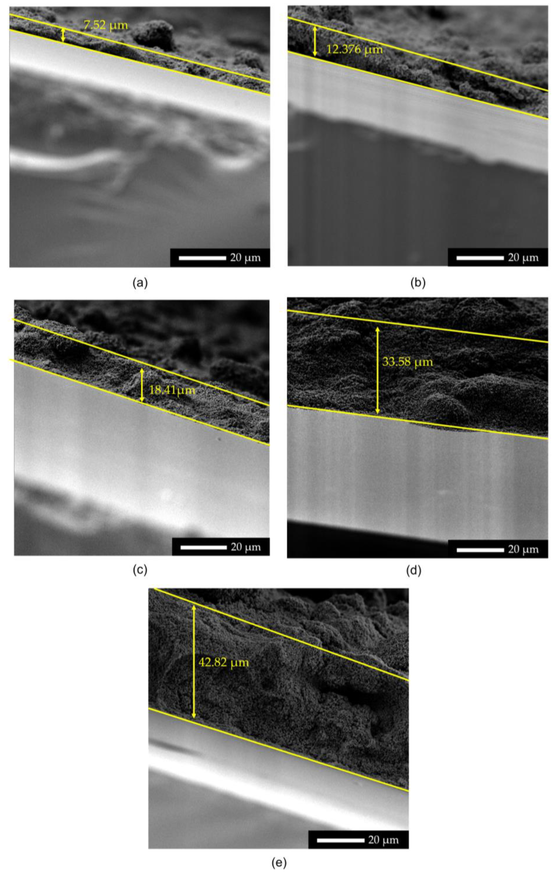
3.1. Structural Properties

Figure 3 shows the XRD patterns of the ZnO photoanode with different layer thicknesses. All samples exhibited similar patterns, except for the peak intensity differences. The Bragg diffractions observed at 2θ degrees of 26.82°, 34.04°, 38.05°, 51.80°, 54.94°, 61.83°, and 65.82° correspond to (110), (011), (020), (121), (220), (130), and (031) of FTO with a tin oxide crystal structure, according to JSCPDS card no. 98-006-3707 [46]. In addition to those associated with the FTO substrate, diffraction peaks at 31.75°, 34.44°, 36.25°, 50.14°, 61.87°, 67.91°, 72.61°, and 76.95° refer to hexagonal wurtzite ZnO (JCPDS 36-1451) [47]. These peaks correspond to (002), (101), (103), (004), and (202) of the ZnO crystal structure. There were no new diffraction peaks, proving that the ZnO films are in the pure wurtzite phase [48] and that no phase transformations occur during heat treatment and layering [49]. The intensity of the ZnO peaks increased with the layer thickness. In contrast, the intensity of the peaks of FTO glass decreased when the ZnO film thickness became thicker.
The average crystallite size was calculated using the aforementioned Equation (1) and XRD data. The crystallite size for all of the layers was almost the same and in the 65–73 nm range. Since the ZnO powder used was a commercially available powder, and all of the ZnO paste preparation techniques were consistent across all of the different layered photoanodes, the results demonstrate that the number of layers added has no discernible impact on the crystallite size [37,49,50].
The cross-section of ZnO photoanodes with different layers is shown in Figure 4. The film thickness of ZnO with one layer is 7.52 µm, two layers are 12.37 µm, three layers are 18.41 µm, four layers are 33.58 µm, and five layers are 42.82 µm. All samples were manufactured using the doctor blade method and annealed at 450 °C; hence, there were no discernible changes in the morphology of the ZnO surface in the samples.
Figure 5 shows the effect of the number of layers on the thickness measurement of the ZnO film layer. The graph shows a linear increase in the thickness measurement when the number of layers applied increased. This proves the basic theory of the doctor blade coating technique, where the thickness of the film increases with the number of coatings applied.

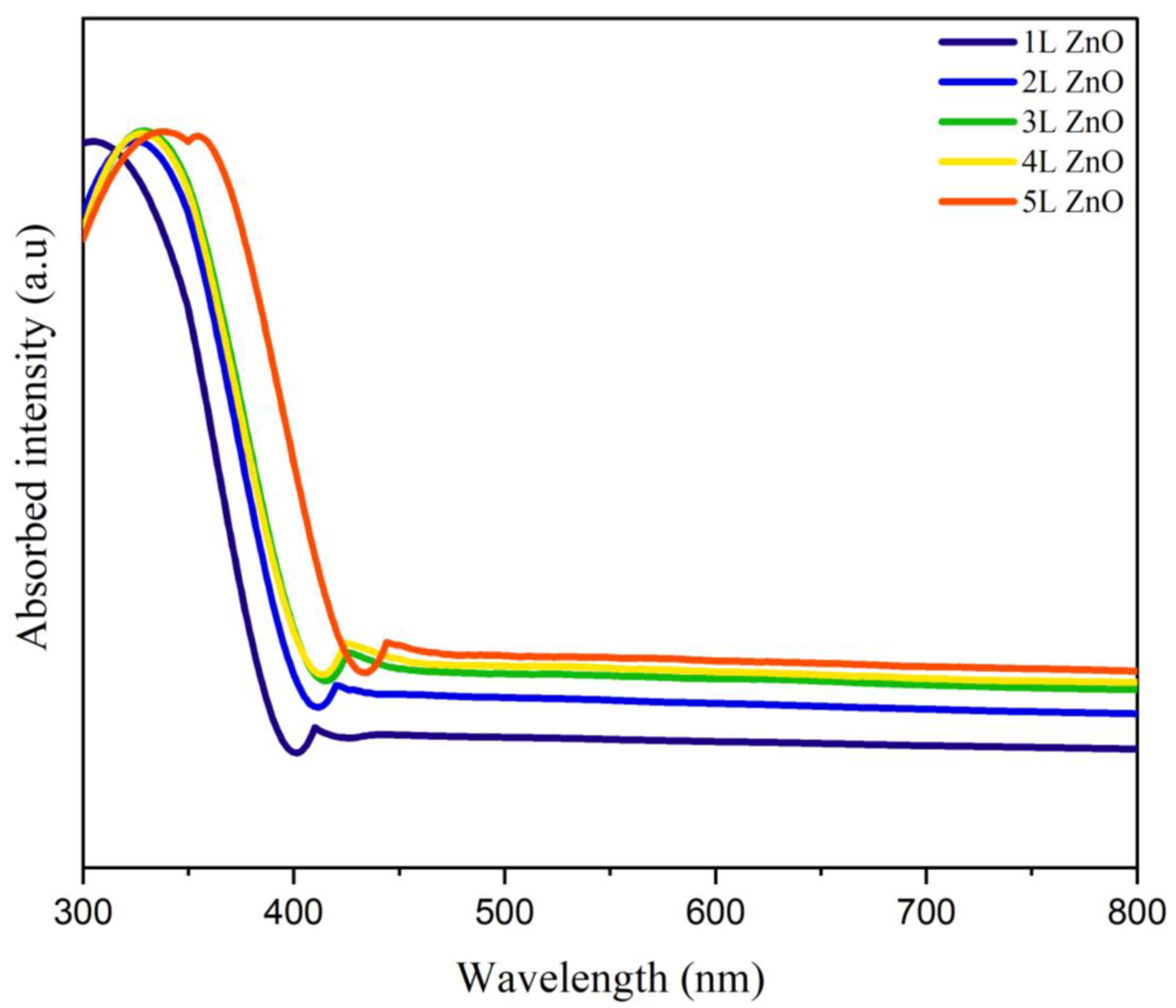
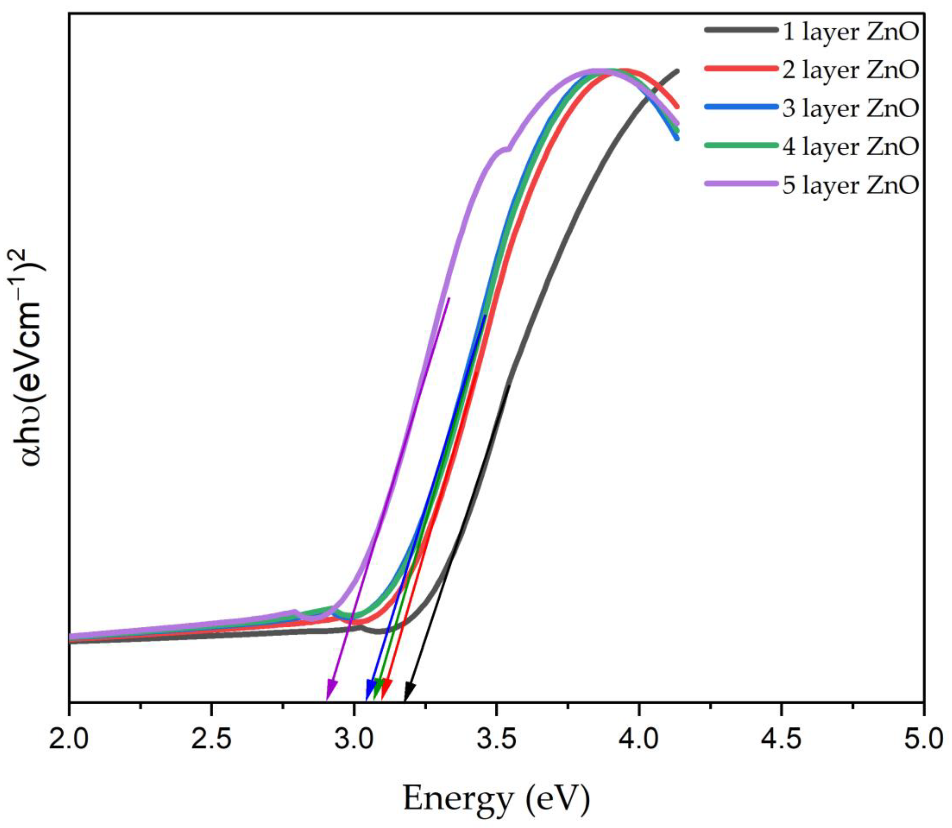
3.2. Optical Properties

Figure 6 shows the optical absorption of the different layer thicknesses of the ZnO photoanode at wavelengths of 300–800 nm. Two regions can be seen in this graph: a significant absorption region (≤370 nm) and a significant transmittance region (≥450 nm). The absorption wavelength shifts to a larger wavelength when the number of layers increases in the absorption region. Generally, the transmittance is influenced by the optical depth and absorbance, including the attenuation cross-section, the number density, the attenuation coefficient and concentration of the attenuating species, and the path length of the radiation beam through the materials [51]. The transmittance decreases with the increasing layer thickness since the transmittance is inversely proportional to the absorbance [52]. In this work, the transmittance region ≥ 450 nm of the photoanode reflects that the sunlight in the visible range and above is being transmitted to the dye for electron–hole pair generation, which directly impacts the photon-to-electricity conversion. A good photoanode should absorb less and transmit more to the dye, but at the same time, it needs to have high electron mobility as the charge carrier.
In order to calculate the band-gap energy, a graph is plotted between photon energy and (αhν)2. The band-gap energies of one, two, three, four, and five layers of ZnO photoanodes are 3.18 eV, 3.10 eV, 3.09 eV, 3.06 eV, and 2.94 eV, respectively, as shown in Figure 7. The band-gap values decrease with the increasing layer thickness. This is due to the increased local levels within the band gap as the thickness of the thin film increases [53]. Hence, the energy band gap of the thin film decreases. A reduction in the band gap increases the conductivity of ZnO since the electrons will require less energy to travel from the valence to the conduction band of ZnO [54]. The calculated band-gap value is lower than the reported band-gap value (3.37 eV). This may be related to the thermal stress effects of the annealing process of the films [55]. The energy band gap of ZnO is 3.37 eV at room temperature. For the DSSC, the ZnO photoanode underwent heat treatment, increasing the photoanode’s temperature. The increase in temperature expanded the crystal lattice and weakened the interatomic bonds. The weaker interatomic bonds require less energy to break and move electrons into the conduction band, which reduces the band gap of the photoanode.
Figure 8 shows the absorbance of photoanodes soaked in N719 dye: one layer for one hour, two layers for two hours, three layers for three hours, and four layers and five layers for four hours. The absorbance of one, two, and three layers soaked in the dye for one, two, and three hours was higher than that of photoanodes with four and five layers in the dye for four hours. This result corresponds to the efficiency of the DSSC, where the three-layered ZnO DSSC has the highest efficiency. As the thickness of the photoanodes increases, the absorbance peak shifts slightly to the visible region. The thickest ZnO film (five layers) absorbs light at around the 350–420 nm wavelength. This phenomenon is known as the bathochromic shift (redshift). It is an effect due to which the absorption maximum is shifted towards a longer wavelength [55,56,57]. Compared to the N719 dye dissolved in ethanol (high polarity), when N719 is absorbed on the nonpolar ZnO photoanode, the bathochromic shift (redshift) occurs and can be seen clearly in the absorbance graph. ZnO is nonpolar, and the redshift occurs when the polarity is decreased or when there is none. The redshift is also caused by the crystallinity of the film. When the layers increase, the crystallinity of the film is improved. Hence, the wavelength becomes greater, which causes the redshift [58].

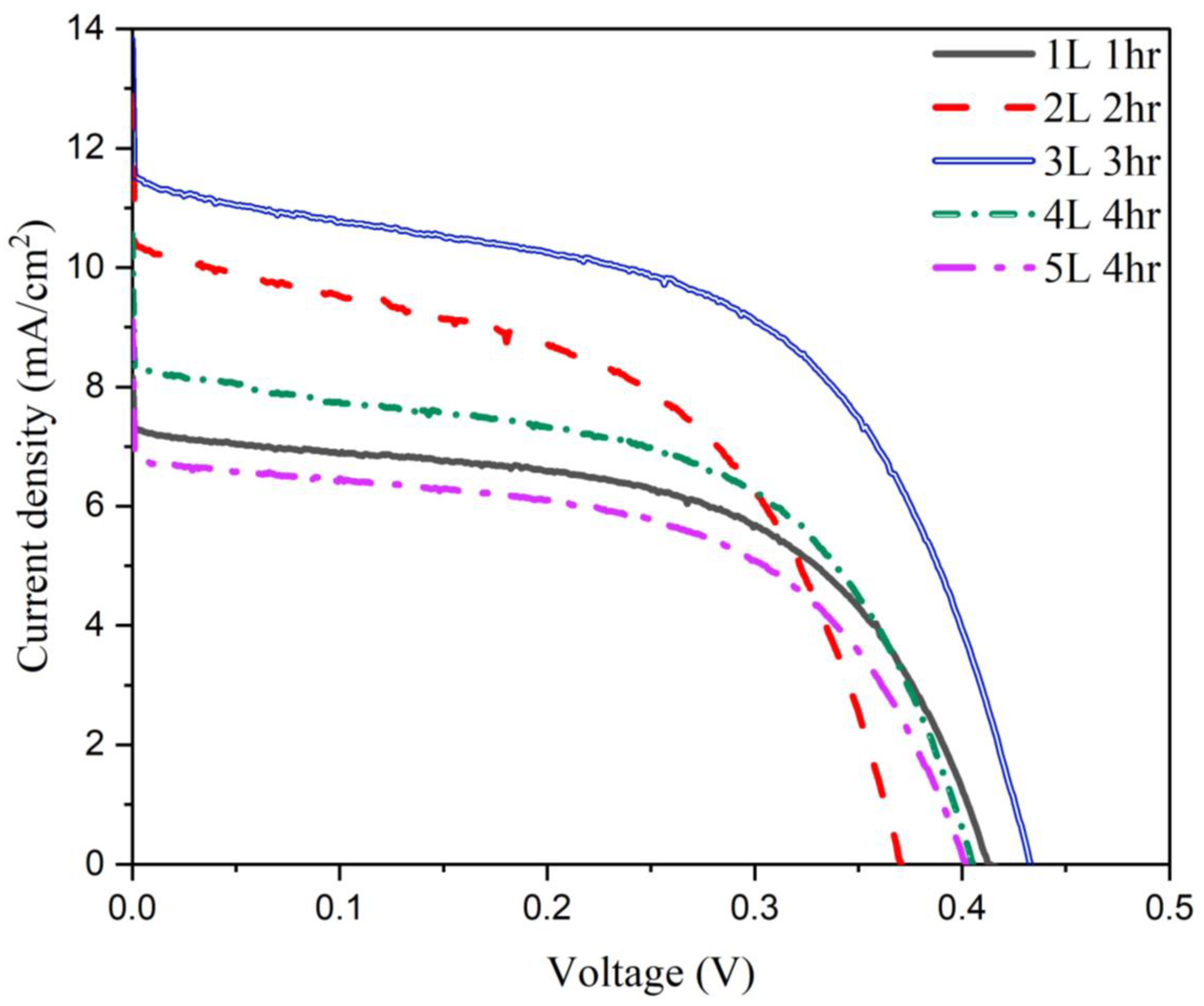
3.3. Electrical Properties

The performance of the synthesized DSSCs was assessed in one-sun AM 1.5 G simulated light. The photovoltaic characteristics of the manufactured DSSCs with various thicknesses and dye soaking times were measured. ZnO photoanodes with different layer thicknesses were each soaked for a different soaking time in N719 dye. Table 1 shows the detailed results.
Figure 9a–d show the relationship between photovoltaic parameters such as the short-circuit current (Jsc), open-circuit voltage (Voc), fill factor (FF), and efficiency (ƞ) of the ZnO DSSC for different dye soaking times and the photoanode layer thickness. As shown in Figure 9a, the Jsc value for the one-layer thickness decreased from 8.6 mA/cm2 to 0.58 mA/cm2 after soaking in the dye for 24 h. The Jsc value increased from 5.92 to 12.87 mA/cm2 after two hours of soaking for the two-layer-thick photoanode. However, the Jsc value decreased to 1.55 mA/cm2 when the soaking time was extended to 24 h. A similar trend can be observed for the three-, four-, and five-layer thicknesses of the photoanode, where the Jsc value increased to maxima of 13.82 mA/cm2, 10.56 mA/cm2, and 9.11 mA/cm2, respectively, until the specific dye soaking time and decreased when reaching 24 h of soaking. This situation is explained by the acidic group of N719 dye, which leads to the strong reaction with Zn2+ ions and the formation of complexes. Prolonged immersion in N719 dye can dissolve the ZnO surface [56].
According to the UV-Vis absorption graph in Figure 8, the light absorption of four- and five-layered ZnO photoanodes was much lower than the other layers. The electrode thickness will also impact the ability to absorb dye. A thicker photoanode has a higher Jsc due to its increased capacity to absorb photons. Suppose that the electrode thickness is greater than the depth of light penetration; in that case, the number of photons useful for electron photogeneration will be constrained. Therefore, Jsc cannot be further increased.
Figure 9b compares the Voc value for the fabricated ZnO DSSCs with different thicknesses. No clear trend was noticeable in the Voc values for the layered ZnO photoanode at different soaking times. The highest Voc was achieved when the three-layered ZnO photoanode was soaked in N719 dye for 3 h. The fill factor (FF) values shown in Figure 9c also do not exhibit any apparent trends, and the FF values vary between 0.32 and 0.51. The conversion efficiency at various dye absorption times and photoanode thicknesses was calculated using Equation (3).
The Jsc and efficiency plots in Figure 9d have similar trends and peak values at the same dye adsorption time. Due to the dye adsorption time’s significantly greater impact on Jsc than other photovoltaic parameters, Jsc is the parameter that determines efficiency. There is a specific optimal dye adsorption time for each photoanode thickness at which the conversion efficiency is at its highest. The best dye adsorption period identified at a specific photoanode thickness does not apply to other thicknesses. The three-layered ZnO photoanode was submerged in the dye for three hours, yielding a 2.77% efficiency, the highest efficiency recorded. Each cell has different readings of Jsc, Voc, FF, and η , which demonstrates how the thickness of the ZnO photoanode is affected by the dye loading time.
The highest efficiency, 1.71%, was achieved by soaking the one-layered ZnO photoanode in the dye for an hour. In contrast, the highest efficiency, 2.77%, was achieved by soaking the three-layered ZnO photoanode in the dye for three hours, as shown in Table 2.
The best dye adsorption time reported at a particular thickness does not apply to other thicknesses because the dye absorption time is either too short or too long for alternative film thicknesses, which affects the cell’s efficiency differently. For example, when a 3 h dye soaking time (optimal for the three-layered ZnO photoanode) was applied for one-, two-, four-, and five-layered ZnO photoanodes, the conversion efficiency dropped from the peak value of 2.77% to approximately 0.67%, 1.61%, 1.72%, and 1.34%, respectively. A prolonged dye adsorption time causes dye aggregation and the etching of the ZnO surface, resulting in the performance deterioration of ZnO photoanodes. Table 2 and Figure 10 summarize each layer’s optimal dye soaking time.
Similar work was reported by Kouhestanian et al. [35], where the thickness of the ZnO photoanode layer was modified by using the doctor blade method. They used synthesized ZnO with particle sizes of 30–350 nm, and the ZnO paste was prepared according to the Ito method. The platinum counter electrode in their research was made via drop coating. In our research, we successfully achieved a higher fill factor (FF) of around 0.42–0.51 compared to other research works. Kouhestanian et al. reported FFs of around 0.34–0.43, and May et al. [33] reported FFs of 0.34–0.47. Increasing the shunt resistance (Rsh) and decreasing the series resistance (Rs) lead to a higher fill factor, thus resulting in greater efficiency. Shunt resistance (Rsh) is due to the leakage across the interface between photoelectrodes and the dye and the presence of crystal defects in the interface region. Series resistance (Rs) is mainly caused by the bulk resistance of semiconductor materials and the contact resistance between the metallic contacts and the semiconductor.

4. Conclusions

This study has shown that the photovoltaic properties of DSSCs depend significantly on the ZnO photoanode thickness and the dye adsorption time. In this work, the DSSC with a three-layer ZnO photoanode achieved a maximum efficiency of 2.77%. The short-circuit current mainly determines the efficiency of the DSSC. Increasing the thickness of the ZnO photoanode to its optimal point improves the absorption of the dye, which increases the light absorption and translates into an increase in device efficiency. However, a continuous process of dye immersion may dissolve the ZnO photoanode and decrease the device’s performance. In this work, it is predicted that the decrease in efficiency with a higher thickness of the photoanode is due to a longer immersion time in the acidic N719 dye and the longer path length for electron transport.

Author Contributions

Conceptualization, M.N.N., N.M. and I.S.M.; methodology, K.M., I.S.M. and S.N.I.; software, M.N.N.; validation, N.M., M.F.M.S., N.A., P.V. and A.V.S.; formal analysis, M.N.N., N.M. and I.S.M.; investigation, K.M. and S.N.I.; resources, N.M., M.F.M.S. and N.A.; data curation, I.S.M., M.N.N., A.V.S., M.N. and P.V.; writing—original draft preparation, K.M.; writing—review and editing, M.N.N., N.M. and I.S.M.; visualization, M.N.N.; supervision, M.N.N., N.M. and I.S.M.; project administration, M.N.N., N.M., I.S.M., M.F.M.S., N.A. and M.A.A.M.S.; funding acquisition, M.N., M.N.N. and M.A.A.M.S. All authors have read and agreed to the published version of the manuscript.

Funding

This research was funded by the Ministry of Higher Education of Malaysia (MoHE) and Universiti Malaysia Perlis (UniMAP) under the Fundamental Research Grant Scheme (FRGS) (Grant number: FRGS/1/2020/TK0/UNIMAP/02/35) and by the Gheorghe Asachi Technical University of Iasi (TUIASI) from the University Scientific Research Fund (FCSU).

Institutional Review Board Statement

Not applicable.

Informed Consent Statement

Not applicable.

Data Availability Statement

Not applicable.

Acknowledgments

The Ministry of Higher Education of Malaysia and Universiti Malaysia Perlis provided financial assistance to the authors under the Fundamental Research Grant Scheme (FRGS) (Grant number: FRGS/1/2020/TK0/UNIMAP/02/35). Special thanks to the Centre of Excellence for Renewable Energy (CERE) Universiti Malaysia Perlis, Centre of Excellence Frontier Materials Research (CFMR) Universiti Malaysia Perlis, and Universiti Tenaga Nasional (@UNITEN, The Energy University of Malaysia) for providing the characterization equipment.

Conflicts of Interest

The authors declare no conflict of interest.

References

  1. Qazi, A.; Hussain, F.; Rahim, N.A.B.D.; Hardaker, G.; Alghazzawi, D.; Shaban, K.; Haruna, K. Towards Sustainable Energy: A Systematic Review of Renewable Energy Sources, Technologies, and Public Opinions. IEEE Access 2019, 7, 63837–63851. [Google Scholar] [CrossRef]
  2. Liu, Y.; Li, Y.; Wu, Y.; Yang, G.; Mazzarella, L.; Procel-Moya, P.; Tamboli, A.C.; Weber, K.; Boccard, M.; Isabella, O.; et al. High-Efficiency Silicon Heterojunction Solar Cells: Materials, Devices and Applications. Mater. Sci. Eng. R. Rep. 2020, 142, 100579. [Google Scholar] [CrossRef]
  3. Shin, D.Y.; Lim, J.R.; Shin, W.G.; Lee, C.G.; Kang, G.H. Layup-Only Modulization for Low-Stress Fabrication of a Silicon Solar Module with 100 Μm Thin Silicon Solar Cells. Sol. Energy Mater. Sol. Cells 2021, 221, 110903. [Google Scholar] [CrossRef]
  4. Pastuszak, J. Photovoltaic Cell Generations and Current Research Directions for Their Development. Materials 2022, 15, 5542. [Google Scholar] [CrossRef] [PubMed]
  5. Khatibi, A. Generation and Combination of the Solar Cells: A Current Model Review. Energy Sci. Eng. 2019, 7, 305–322. [Google Scholar] [CrossRef] [Green Version]
  6. Wu, C.; Wang, K.; Batmunkh, M.; Bati, A.S.R.; Yang, D.; Jiang, Y.; Hou, Y.; Shapter, J.G.; Priya, S. Nano Energy Multifunctional Nanostructured Materials for next Generation Photovoltaics. Nano Energy 2020, 70, 104480. [Google Scholar] [CrossRef]
  7. Ananthakumar, S.; Kumar, J.R.; Babu, S.M. Third-Generation Solar Cells: Concept, Materials and Performance—An Overview. In Environmental Chemistry for a Sustainable World; Springer Nature Switzerland AG.: Cham, Switzerland, 2019; pp. 305–339. ISBN 9783030044749. [Google Scholar]
  8. Michaels, H. Chemical Science Challenges and Prospects of Ambient Hybrid Solar Cell Applications. Chem. Sci. 2021, 12, 5002–5015. [Google Scholar] [CrossRef]
  9. Abdelhameed, M.; Jevasuwan, W.; Subramani, T.; Chen, J.; Fukata, N. Efficiency Enhancement of Si Nanostructure Hybrid Solar Cells by Optimizing Non-Radiative Energy Transfer from Si Quantum Dots. Nano Energy 2021, 82, 105728. [Google Scholar] [CrossRef]
  10. Sampaio, P.G.V.; González, M.O.A. Photovoltaic Solar Energy: Conceptual Framework. Renew. Sustain. Energy Rev. 2017, 74, 590–601. [Google Scholar] [CrossRef]
  11. Hagfeldt, A.; Vlachopoulos, N. Dye-Sensitized Solar Cells. In The Future of Semiconductor Oxides in Next-Generation Solar Cells; Elsevier: Amsterdam, the Netherlands, 2018; pp. 183–239. ISBN 9780128111659. [Google Scholar]
  12. Sugathan, V.; John, E.; Sudhakar, K. Recent Improvements in Dye Sensitized Solar Cells: A Review. Renew. Sustain. Energy Rev. 2015, 52, 54–64. [Google Scholar] [CrossRef]
  13. Pramananda, V.; Hadyan Fityay, T.A.; Misran, E. Anthocyanin as Natural Dye in DSSC Fabrication: A Review. IOP Conf. Ser. Mater. Sci. Eng. 2021, 1122, 012104. [Google Scholar] [CrossRef]
  14. Mohammadian-Sarcheshmeh, H.; Arazi, R.; Mazloum-Ardakani, M. Application of Bifunctional Photoanode Materials in DSSCs: A Review. Renew. Sustain. Energy Rev. 2020, 134, 110249. [Google Scholar] [CrossRef]
  15. Nien, Y.H.; Chen, H.H.; Hsu, H.H.; Kuo, P.Y.; Chou, J.C.; Lai, C.H.; Hu, G.M.; Kuo, C.H.; Ko, C.C. Enhanced Photovoltaic Conversion Efficiency in Dye-Sensitized Solar Cells Based on Photoanode Consisting of TiO2/GO/Ag Nanofibers. Vacuum 2019, 167, 47–53. [Google Scholar] [CrossRef]
  16. Devadiga, D.; Selvakumar, M.; Shetty, P.; Santosh, M.S. Recent Progress in Dye Sensitized Solar Cell Materials and Photo-Supercapacitors: A Review. J. Power Sources 2021, 493, 229698. [Google Scholar] [CrossRef]
  17. Magiswaran, K.; Norizan, M.N.; Mohamad, I.S.; Mahmed, N.; Idris, S.N.; Sobri, S.A. Charge Recombination in Zinc Oxide-Based Dye-Sensitized Solar Cell: A Mini Review. Int. J. Nanoelectron. Mater. 2021, 14, 59–66. [Google Scholar]
  18. Vizureanu, P.; Samoila, C.; Cotfas, D. Materials Processing Using Solar Energy. Environ. Eng. Manag. J. 2009, 8, 301–306. [Google Scholar] [CrossRef]
  19. Rambu, A.P.; Sirbu, D.; Sandu, A.V.; Prodan, G.; Nica, V. Influence of In Doping on Electro-Optical Properties of ZnO Films. Bull. Mater. Sci. 2013, 36, 231–237. [Google Scholar] [CrossRef]
  20. Borsos, Z.; Paun, V.-P.; Botez, I.C.; Stoica, C.-M.; Vizureanu, P.; Agop, M. Structural Conductivity of Carbon Nanotubes. Rev. Chim. 2008, 59, 1169–1171. [Google Scholar] [CrossRef]
  21. Kang, S.H.; Kim, J.Y.; Kim, H.S.; Koh, H.D.; Lee, J.S.; Sung, Y.E. Influence of Light Scattering Particles in the TiO2 Photoelectrode for Solid-State Dye-Sensitized Solar Cell. J. Photochem. Photobiol. A Chem. 2008, 200, 294–300. [Google Scholar] [CrossRef]
  22. Omar, A.; Ali, M.S.; Abd Rahim, N. Electron Transport Properties Analysis of Titanium Dioxide Dye-Sensitized Solar Cells (TiO2-DSSCs) Based Natural Dyes Using Electrochemical Impedance Spectroscopy Concept: A Review. Sol. Energy 2020, 207, 1088–1121. [Google Scholar] [CrossRef]
  23. Deepa, H.A.; Madhu, G.M.; Venkatesham, V. Performance Evaluation of DSSC’s Fabricated Employing TiO2 and TiO2-ZnO Nanocomposite as the Photoanodes. Mater. Today Proc. 2021, 46, 4579–4586. [Google Scholar] [CrossRef]
  24. Jamalullail, N.; Mohamad, I.S.; Norizan, M.N.; Mahmed, N.; Taib, B.N. Recent Improvements on TiO 2 and ZnO Nanostructure Photoanode for Dye Sensitized Solar Cells: A Brief Review. EPJ Web Conf. 2017, 162, 01045. [Google Scholar] [CrossRef] [Green Version]
  25. Parihar, V.; Raja, M.; Paulose, R. A Brief Review of Structural, Electrical and Electrochemical Properties of Zinc Oxide Nanoparticles. Rev. Adv. Mater. Sci. 2018, 53, 119–130. [Google Scholar] [CrossRef]
  26. Wu, M.S.; Yang, R.S. Post-Treatment of Porous Titanium Dioxide Film with Plasmonic Compact Layer as a Photoanode for Enhanced Dye-Sensitized Solar Cells. J. Alloys Compd. 2018, 740, 695–702. [Google Scholar] [CrossRef]
  27. Gan, Y.K.; Zakaria, N.F.; Mohamad, I.S.; Norizan, M.N. The Effect of ZnO Photoanode Solution Ageing to the Performance of Dye-Sensitized Solar Cell (DSSC). In Proceedings of the AIP Conference Proceedings, Putrajaya, Malaysia, 22 August 2019; Volume 2203, p. 020048. [Google Scholar]
  28. He, Y.; Hu, J.; Xie, Y. High-Efficiency Dye-Sensitized Solar Cells of up to 8.03% by Air Plasma Treatment of ZnO Nanostructures. Chem. Commun. 2015, 51, 16229–16232. [Google Scholar] [CrossRef]
  29. Dennyson Savariraj, A.; Mangalaraja, R.V.V. Function of Photoanode: Charge Transfer Dynamics, Challenges, and Alternative Strategies. In Interfacial Engineering in Functional Materials for Dye-Sensitized Solar Cells; John Wiley & Sons: New York, NY, USA, 2019; pp. 17–33. [Google Scholar] [CrossRef]
  30. Aksoy, S.; Polat, O.; Gorgun, K.; Caglar, Y.; Caglar, M. Li Doped ZnO Based DSSC: Characterization and Preparation of Nanopowders and Electrical Performance of Its DSSC. Phys. E Low-Dimens. Syst. Nanostructures 2020, 121, 114127. [Google Scholar] [CrossRef]
  31. Mohamad, I.S.; Norizan, M.N.; Hanifiah, M.K.F.M.; Amin, I.A.M.; Shahimin, M.M. Fabrication and Characterization of ZnO:In Thin Film as Photoanode for DSSC Using Natural Fruit Dyes. In Proceedings of the AIP Conference Proceedings, Penang, Malaysia, 28–30 May 2014; Volume 1660, p. 070049. [Google Scholar]
  32. Giannouli, M.; Govatsi, Κ.; Syrrokostas, G.; Yannopoulos, S.; Leftheriotis, G. Factors Affecting the Power Conversion Efficiency in ZnO DSSCs: Nanowire vs. Nanoparticles. Materials 2018, 11, 411. [Google Scholar] [CrossRef] [Green Version]
  33. Toe, M.Z.; Pung, S.Y.; Yaacob, K.A.B.; Han, S.S. Effect of Dip-Coating Cycles on the Structural and Performance of ZnO Thin Film-Based DSSC. Arab. J. Sci. Eng. 2021, 46, 6741–6751. [Google Scholar] [CrossRef]
  34. Wali, Q.; Fakharuddin, A.; Jose, R. Tin Oxide as a Photoanode for Dye-Sensitised Solar Cells: Current Progress and Future Challenges. J. Power Sources 2015, 293, 1039–1052. [Google Scholar] [CrossRef] [Green Version]
  35. Kouhestanian, E.; Ranjbar, M.; Mozaffari, S.A.; Salaramoli, H. Investigating the Effects of Thickness on the Performance of ZnO-Based DSSC. Prog. Color. Color. Coat. 2021, 14, 101–112. [Google Scholar]
  36. Rashid, A.R.A.; Kamarudin, N.A.; Mohamad, I.S.; Norizan, M.N. Effect of Thickness and Ageing Time on Optical Properties of Zinc Oxide Film Using Sol-Gel Method. Int. J. Nanoelectron. Mater. 2019, 11, 187–194. [Google Scholar]
  37. Jazmati, A.K.; Abdallah, B. Optical and Structural Study of ZnO Thin Films Deposited by RF Magnetron Sputtering at Different Thicknesses: A Comparison with Single Crystal. Mater. Res. 2018, 21, 1–6. [Google Scholar] [CrossRef]
  38. Zamiri, G.; Bagheri, S.; Babadi, A.A.; Moosavi, S.; Naghavi, M.S. The Impact of Immerssion Time and Thickness of TiO2 Photoanode on Power Conversion Efficiency of Dye-Sensitised Solar Cells Using Graphene Quantum Dots as Photosensitiser. Opt. Mater. 2021, 122, 111720. [Google Scholar] [CrossRef]
  39. Fathima, M.I.; Wilson, K.S.J. Role of Multilayer Antireflective Coating in ZnO Based Dye Sensitized Solar Cell. Vacuum 2019, 165, 58–61. [Google Scholar] [CrossRef]
  40. Sengupta, D.; Das, P.; Mondal, B.; Mukherjee, K. Effects of Doping, Morphology and Film-Thickness of Photo-Anode Materials for Dye Sensitized Solar Cell Application—A Review. Renew. Sustain. Energy Rev. 2016, 60, 356–376. [Google Scholar] [CrossRef]
  41. Syrrokostas, G.; Leftheriotis, G.; Yianoulis, P. Effect of Acidic Additives on the Structure and Performance of TiO 2 Films Prepared by a Commercial Nanopowder for Dye-Sensitized Solar Cells. Renew. Energy 2014, 72, 164–173. [Google Scholar] [CrossRef]
  42. Kaliva, M.; Vamvakaki, M. Materials Characterization; Elsevier Inc.: Amsterdam, the Netherlands, 2010; Volume 1242, ISBN 9781605112190. [Google Scholar]
  43. Raj, S.; Chand Mali, S.; Trivedi, R. Green Synthesis and Characterization of Silver Nanoparticles Using Enicostemma Axillare (Lam.) Leaf Extract. Biochem. Biophys. Res. Commun. 2018, 503, 2814–2819. [Google Scholar] [CrossRef]
  44. Drygala, A. Influence of TiO2film Thickness on Photovoltaic Properties of Dye-Sensitized Solar Cells. IOP Conf. Ser. Earth Environ. Sci. 2021, 642, 012001. [Google Scholar] [CrossRef]
  45. Sinha, D.; De, D.; Goswami, D.; Mondal, A.; Ayaz, A. ZnO and TiO2 Nanostructured Dye Sensitized Solar Photovoltaic Cell. Mater. Today Proc. 2019, 11, 782–788. [Google Scholar] [CrossRef]
  46. Ravikumar, P.; Ravichandran, K.; Sakthivel, B. Effect of Thickness of SnO2:F over Layer on Certain Physical Properties of ZnO:Al Thin Films for Opto-Electronic Applications. J. Mater. Sci. Technol. 2012, 28, 999–1003. [Google Scholar] [CrossRef]
  47. Widiyandari, H.; Wijayanti, S.; Prasetio, A.; Purwanto, A. ZnO Hollow Sphere Prepared by Flame Spray Pyrolysis Serves as an Anti-Reflection Layer That Improves the Performance of Dye-Sensitized Solar Cells. Opt. Mater. 2020, 107, 110077. [Google Scholar] [CrossRef]
  48. Liu, H.; Liu, H.; Yang, J.; Zhai, H.; Liu, X.; Jia, H. Microwave-Assisted One-Pot Synthesis of Ag Decorated Flower-like ZnO Composites Photocatalysts for Dye Degradation and NO Removal. Ceram. Int. 2019, 45, 20133–20140. [Google Scholar] [CrossRef]
  49. Ali, R.S.; Sharba, K.S.; Jabbar, A.M.; Chiad, S.S.; Abass, K.H.; Habubi, N.F. Characterization of ZnO Thin Film/p-Si Fabricated by Vacuum Evaporation Method for Solar Cell Applications. NeuroQuantology 2020, 18, 26–31. [Google Scholar] [CrossRef]
  50. Jamalullail, N.; Smohamad, I.; Nnorizan, M.; Mahmed, N. Enhancement of Energy Conversion Efficiency for Dye Sensitized Solar Cell Using Zinc Oxide Photoanode. IOP Conf. Ser. Mater. Sci. Eng. 2018, 374, 012048. [Google Scholar] [CrossRef]
  51. Qasem, A.; Mostafa, M.S.; Yakout, H.A.; Mahmoud, M.; Shaaban, E.R. Determination of Optical Bandgap Energy and Optical Characteristics of Cd30Se50S20 Thin Film at Various Thicknesses. Opt. Laser Technol. 2022, 148, 107770. [Google Scholar] [CrossRef]
  52. Menzel, J.P.; Noble, B.B.; Blinco, J.P.; Barner-Kowollik, C. Predicting Wavelength-Dependent Photochemical Reactivity and Selectivity. Nat. Commun. 2021, 12, 1–12. [Google Scholar] [CrossRef]
  53. Abdelfatah, M.; Ismail, W.; El-Shafai, N.M.; El-Shaer, A. Effect of Thickness, Bandgap, and Carrier Concentration on the Basic Parameters of Cu2O Nanostructures Photovoltaics: Numerical Simulation Study. Mater. Technol. 2020, 36, 712–720. [Google Scholar] [CrossRef]
  54. Salau, A.O.; Olufemi, A.S.; Oluleye, G.; Owoeye, V.A.; Ismail, I. Modeling and Performance Analysis of Dye-Sensitized Solar Cell Based on ZnO Compact Layer and TiO2photoanode. Mater. Today Proc. 2022, 51, 502–507. [Google Scholar] [CrossRef]
  55. Yeoh, M.E.; Chan, K.Y.; Wong, H.Y. Investigation on the Thickness Effect of Tio2 Photo-Anode on Dye-Sensitized Solar Cell Performance. Solid State Phenom. 2018, 280, 76–80. [Google Scholar] [CrossRef]
  56. Picollo, M.; Aceto, M.; Vitorino, T. UV-Vis Spectroscopy. Phys. Sci. Rev. 2019, 4, 1–14. [Google Scholar] [CrossRef]
  57. Begum, R.; Farooqi, Z.H.; Naseem, K.; Ali, F.; Batool, M.; Xiao, J.; Irfan, A. Applications of UV/Vis Spectroscopy in Characterization and Catalytic Activity of Noble Metal Nanoparticles Fabricated in Responsive Polymer Microgels: A Review. Crit. Rev. Anal. Chem. 2018, 48, 503–516. [Google Scholar] [CrossRef] [PubMed]
  58. Kumar, C.S.S.R. UV-VIS and Photoluminescence Spectroscopy for Nanomaterials Characterization; Springer Nature Switzerland AG.: Cham, Switzerland, 2013; ISBN 9783642275944. [Google Scholar]
Figure 1. ZnO paste application by doctor blade method.
Coatings 13 00020 g001
Figure 2. (a) ZnO photoanode soaked in dye; (b) platinum-coated FTO; (c) FTO glass with hole; (d) assembly of cell and insertion of electrolyte.
Coatings 13 00020 g002
Figure 3. XRD graph of ZnO photoanode with different film layers.
Coatings 13 00020 g003
Figure 4. Cross-section of ZnO photoanodes on FTO glass: (a) 1 layer, (b) 2 layers, (c) 3 layers, (d) 4 layers, and (e) 5 layers.
Coatings 13 00020 g004
Figure 5. Number of layers of ZnO film applied vs. the thickness of the ZnO film.
Coatings 13 00020 g005
Figure 6. The absorbance of the ZnO photoanode without dye.
Coatings 13 00020 g006
Figure 7. Tauc plot of the different thicknesses of ZnO film layers without dye.
Coatings 13 00020 g007
Figure 8. The absorbance spectrum of ZnO film with different layer thicknesses soaked in dye for different soaking times.
Coatings 13 00020 g008
Figure 9. Relationship between the photovoltaic parameters of the ZnO DSSC on dye soaking time and the photoanode thickness: (a) Jsc (b) Voc (c) FF, and (d) efficiency.
Coatings 13 00020 g009
Figure 10. The J-V curve for the cell at optimal dye soaking time for each layer.
Coatings 13 00020 g010
Table 1. One- to five-layered ZnO photoanodes soaked in N719 dye for different soaking times.
No. of LayersDye Soaking TimeJsc (mA/cm2)Voc (V)FFη (%)
1 layer1 h
2 h
3 h
4 h
24 h
8.16
4.42
3.54
2.37
0.58
0.41
0.37
0.40
0.38
0.38
0.51
0.46
0.47
0.50
0.46
1.71
0.75
0.67
0.45
0.10
2 layers1 h
2 h
3 h
4 h
24 h
5.92
12.87
8.97
7.71
1.55
0.37
0.37
0.41
0.37
0.40
0.44
0.42
0.44
0.41
0.34
0.97
2.01
1.61
1.18
0.21
3 layers1 h
2 h
3 h
4 h
24 h
4.49
9.55
13.82
10.08
2.21
0.41
0.41
0.43
0.40
0.42
0.43
0.40
0.46
0.40
0.46
0.79
1.57
2.77
1.59
0.43
4 layers1 h
2 h
3 h
4 h
24 h
4.14
5.17
9.77
10.56
2.07
0.41
0.41
0.42
0.41
0.41
0.39
0.44
0.42
0.44
0.32
0.67
0.92
1.72
1.87
0.27
5 layers1 h
2 h
3 h
4 h
24 h
2.66
4.35
7.10
9.11
2.01
0.41
0.40
0.42
0.40
0.42
0.36
0.38
0.45
0.42
0.39
0.04
0.66
1.34
1.53
0.32
Table 2. Photo-voltage characteristics for the cell at optimal dye soaking time for each layer.
No. of
Layers
Dye Soaking TimeJsc (mA/cm2)Voc (V)Fill Factor (FF)η (%)
11 h8.160.410.511.71
22 h12.870.370.422.01
33 h13.820.430.462.77
44 h10.560.410.441.87
54 h9.110.400.421.53
Disclaimer/Publisher’s Note: The statements, opinions and data contained in all publications are solely those of the individual author(s) and contributor(s) and not of MDPI and/or the editor(s). MDPI and/or the editor(s) disclaim responsibility for any injury to people or property resulting from any ideas, methods, instructions or products referred to in the content.

