Article

Sensitization to Corrosion of Austenitic Stainless Steels: Watch Straps Intended to Come into Direct and Prolonged Contact with Skin

Scientific Independent Consultant Biomaterials and Medical Devices, 2074 Marin-Neuchâtel, Switzerland
Coatings 2023, 13(1), 18; https://doi.org/10.3390/coatings13010018
Submission received: 19 October 2022 / Revised: 14 December 2022 / Accepted: 16 December 2022 / Published: 22 December 2022
(This article belongs to the Special Issue Anti-corrosion Coatings of Metals and Alloys – New Perspectives)

Abstract

:
Nine grades of steel from different European steelmakers, namely 304L, 316L, and 904L, were evaluated. The austenitic steels studied are used in the manufacture of watch straps. The evaluations have been carried out in accordance with the ASTM standards which specifically concern the forms of corrosion, pitting (G48-11, FeCl3), intergranular (A262-15, Strauss method) test and Tuccillo–Nielsen test. The polarization electrochemical test on link watch straps was implemented by the microelectrode technique. Stress corrosion has also been investigated in the assembly of laser welded pin and link. It should be noted that, despite the fact that the grade of steel is in conformity with the classification standards, we note that the corrosion behavior is very different from one steelmaker to another. There are parameters that can change the quality of steel such as the technology process, casting volume, deoxidizers’ addition, remelted steel process and traces of pollutants. In consequence, we observe an extensive dispersion of results concerning nickel release, according to the EN 1811 European legislation regarding the protection of the population’s health, specifically relating to skin contact. In conclusion, steels DIN 1.4441 (316L Med) and DIN 1.4539 (904L) present a very good resistance to the morphologies of pitting and crevice corrosion. The 316L and 304L steel grades, also known as DIN 1.4435, DIN 1.4404 and DIN 1.4306, display a major difference in pitting and crevice corrosion behavior.

1. Introduction

In 1924, William Herbert Hatfield (1882–1943) developed the “18/8” steel (18% chromium and 8% nickel, by mass) which is probably the most representative of the iron–nickel–chromium stainless steels, manufactured and used worldwide.
Depending on the chemical composition, three families of stainless steels have been designated: (a) chromium steels; (b) chromium–nickel steels; (c) chromium–nickel–molybdenum steels.
Stainless steels can be defined as alloys containing more than 50% iron and more than 12% chromium.
The structures encountered in stainless steels are similar to those of their main constituent: iron, consisting of two crystalline forms, depending on the temperature:
-
between 912 and 1394 °C, a face centered cubic phase, called austenite or γ phase. As the heated austenite is quickly cooled by quenching, it is transformed into martensite, which corresponds to the structure of hardened steel. This transformation can only be carried out in certain alloys containing carbon; it considerably increases the mechanical resistance, to the detriment of deformability. Austenite is characterized as non-magnetic, ductile at any temperature and with strong hardening.
-
between 770 and 910 °C, a centered cubic phase, known as ferrite α, is formed, and δ is formed between 1394 °C and 1538 °C. The two phases are similar. Ferrite is characterized as magnetic, fragile at low temperature, with medium ductility and limited hardening. Ferrite cannot transform into martensite.
Despite the fact that they are called stainless steels, austenitic steels are highly sensitive to localized corrosion, namely pitting, crevice and intergranular corrosion [1].
Wristwatches are objects which, upon wearing, come into contact with skin. They are subject to localized corrosion, particularly pitting and crevice corrosion, and galvanic corrosion in a sulfide–chloride medium, but also to severe wear in the joints of the bracelets. Regulatory compliance of the metals which are a part of the wristwatches’ composition is a prerequisite. The joint study of corrosion, metal release and cytotoxicity makes it possible to validate a selection of materials that comply with toxicological and allergic safety requirements.
Annex XVII REACH [2] stipulates that these shall not be used in articles intended to come into direct and prolonged contact with the skin, such as: earrings, necklaces, bracelets and chains, anklets, finger rings, watch cases, watch straps, etc., if the rate of nickel release from the parts of these articles coming into direct and prolonged contact with the skin is greater than 0.5 μg/cm2/week. Our study is limited to metal materials (steel) supposed to be used in the manufacture of articles which come in prolonged contact with the skin, specific to watchmaking, such as bracelets.
Watch cases are typically composed of medium grades of austenitic stainless steels. The grades of the family DIN 1.14306 (304L), DIN 1.4435 (316L), DIN 1.4441 (316L) and DIN 1.4539 (904L) are commonly used. In principle, in a bracelet there are three grades of steel, one for the link (904L or 316L Medical), another for the pin (316L) and another for the clasp (304L). The austenitic stainless steels taken into consideration are characterized by a very low carbon content and significant additions of nickel, chromium and molybdenum. They have the property of developing a passive layer under anodic conditions, which is formed mainly by chromium and molybdenum oxides.
Molybdenum plays a decisive role in the stability of this layer. Improved corrosion resistance cannot be obtained by increasing the amount of these elements. In essence, the most highly alloyed stainless steels can develop intermetallic precipitation during their heat treatment. These are at the origin of a loss of stability of the passive layer by depletion of two elements: chromium and molybdenum [3,4].
The development of grades with greater corrosion resistance and metallurgical stability can be obtained through the combination of nitrogen and manganese additions. It is thus possible to match the very austenitic 904L grade with a grade that is significantly less alloyed and mechanically more resistant [5,6,7,8,9,10].
These stainless steels would be relatively soft, mechanically weak and exhibit good resistance to generalized corrosion [11].
The hardness for each is as follows: for annealed 304L, 150–180 HV [12], for annealed 316L, 160–200 HV [13], for annealed 316L Medical, 160–200 HV [14] and annealed 904L, 150 HV [15].
The quantitative ratings and markings of the overall corrosion resistance, referred to as pitting resistance equivalent number (PREN), for these stainless steels are as follows: for 304L, 18.112, for 316L, 25.865 and for 904L, 38.891.
Grades 316L (DIN 1.4441) and 904L (DIN 14539) are made by vacuum melting and remelting, which give them high inclusion cleanliness and reduce the risk of pitting.
On the other hand, the passive layer is nevertheless insufficient to ensure complete immunity in all cases of localized corrosion encountered during wear.
Passivity, in general, represents a kinetic inhibition of the ability of metals and alloys to react with the environment in contact with their surface. Passivity results in the formation of an ultra-thin oxide film (3–100 Å), compact and dense, free of porosity, which uniformly covers the metal surface [16]. Specialty literature shows that the presence of molybdenum and nitrogen in certain quantities in the steels’ composition facilitates the formation of the passivation layer for their protection against pitting and crevice corrosion [17,18,19].
Thus, the purpose of this study has been to evaluate the corrosion resistance of the watch bracelet, as well as the efficiency of the passivation process of austenitic steels used in the manufacture of the bracelets.
The evaluation tests are carried out on links and strands obtained by the disassembly of straps supposed to be in contact with the consumer.
If the links are machined from the transverse face, there is a significant risk of inducing contact allergies with skin [20,21]. So, the purpose of this study is also to alert and inform the watch strap manufacturer.
Another aspect is to make the choice from the corrosion point of view between a mounting system pin/link welded microlaser and link/driven pin.
The purpose of this work is also to collect information that can help the watch manufacturer and the steelmaker to develop a new generation of specific steels, destined for use in the watchmaking industry.

2. Materials and Methods

2.1. Characteristics of the Watch Straps

A watch strap is an assembly of several metallic components. For a better understanding, in Figure 1 we present a strand of a bracelet. It consists of a main link called the H profile, which is connected to two central links with the two pins driven into the holes of the links. In the assembly of the bracelets, the central link pin is welded by the plasma laser spot welding process.
The most commonly used welding techniques include manual, automatic and robotic tungsten inert gas (TIG), continuous YAG laser, pulsed YAG and CO2 and hybrid laser/arc welding.
In the case of watch straps, galvanic couplings and the corrosion sensitivity of steels can generate amounts of released nickel. These are in non-compliance with the current legislation regarding the protection of the population’s health, as, upon skin contact, they can lead to nickel allergies. On the other hand, the release of other cations also poses toxicology problems (toxic for reproduction (CMR), general toxicology threats, sanitization issues and allergies in humans. In Europe, the USA, Canada, Japan, Korea and China, for objects which contain nickel and are intended for permanent contact with skin, the European and specific national legislative bodies have imposed a ban if the rate of nickel release of 0.5 µg/cm2 week-1 is exceeded [22,23].

2.2. Grades of Austenitic Steels Tested

In our study, we tested only grades of austenitic steels produced in Europe. The nominal chemical composition, according to the manufacturer, is given in Table 1.

2.3. The Passivation of Stainless Steels

Passivity is the result of the formation of a layer with low electrical conductivity on the metal surface. Various theories have been developed to explain the formation of the passive layer. It has been proven that the thinner the film, the better its protective capacity [24,25,26,27,28]. The important issue how it has been formed, what is its structure and stability in a given corrosive environment. Three models which explain the formation of the passivation films have been considered:
(a)
the dissolution–precipitation model: Müller supposed that the initial cause of passivity is the accumulation on the surface of electrolysis products (salts or basic salts of the metal), in a crystal form. Thus, the passivity consists in the crystallization of metal salts in the pores of the natural oxide [29];
(b)
the nucleation model: Armstrong, Fleischman and Thyrsk have a different opinion [24]. They propose a model of film formation by a conventional nucleation mechanism with a progressive increase in nucleation sites. Based on this model, several mechanisms for the formation of the passivation layers for iron and cadmium have been developed [30];
(c)
the adsorption model: proposed by Bockris [31], Foroulis [25], Kabanov [26], Kolotîrkin [27] and Frankenthal [28]. The adsorption model assumes that the main event (the formation of oxide at the surface) occurs at more negative potentials than the adsorption potentials of O−2 and OH.
To summarize, the surface of passive metals is covered by an oxide passive layer (passive film), which separates the metal from the electrolyte, unlike active metals which come in direct contact with the electrolyte.
Alloys and metals with high corrosion resistance in a given medium are generally in the passive state. Passing of cations into solution from the surface of a metal or alloy (dissolving a metal), which is free of a passivation layer, is known as active dissolution.
When a metal covered by a passivation layer dissolves, a passive dissolution process takes place. In this case, the cations formed at the metal–film interface diffuse in the electrolyte.
The dissolution of the passive film corresponds to a certain electrochemical potential (Ep). The passivation of a metal or an alloy takes place only if its electrical potential, generated at the film–electrolyte interface, exceeds the passivation potential (Ep). The passivation potential Ep, determined from the polarization curve, is the transition potential from the active state domain to the passive state domain.
There are two ways to reach the passivation state: by chemical reaction of an oxidant, also known as spontaneous passivation or chemical passivation, and by anodic polarization, also known as anodization.
The passivation process depends on the kinetics of active dissolution in a given medium, the mass transport of dissolution products, the pH and the temperature of the medium, the water content, the chemical composition and the presence of certain chemical elements [32].
In the case of stainless steels, the presence of chromium, nickel, copper and molybdenum inhibits anodic dissolution and facilitates the passivation tendency of the surface [33,34,35,36].

2.4. Watch Strap Sample Preparation

Link/pin assemblies, belonging to a watch strap, were contained in resin and polished. In order to study the various electrochemical quantities specific to the interface’s laser weld/link, laser weld/pin, both longitudinal and transverse samples were prepared.
A light and rapid metallographic attack, carried out in the same way for all the samples, enabled us to highlight the welding cord, in order to determine the correct position of the microelectrode (Figure 2a,b).
Corrosion assessment of welded link/pin assemblies were studied via the microelectrode technique. The schematic representation of the microelectrode technique is illustrated in Figure 3.
The system consists of a circular test surface with a diameter of 200 μm and, like the conventional cell, includes a working electrode (the surface of the sample to be tested), a counter electrode (platinum wire) and an SCE reference electrode. The electrolyte, with a volume of approximately 2 mL, is an artificial sweat according to standard EN 1811 (pH 4.5), not buffered with NaOH (1 g/L of urea, 5 g/L of NaCl and 940 μm/L of racemic lactic acid). The measurement system is controlled by an Eg&G PARSTAT 4000 potentiostat–galvanostat (Princeton Applied Research, Oak Ridge, TN, USA), equipped with LC Low Current Interface, in a current scale with an auto-current ranging capability from 200 Ma–4 pA limit (80 fA minimum range). The measuring system is protected by a Faraday cage, surrounded by a Helmholtz cage (Figure 4).
The samples underwent the following measurement cycle:
-
Eop: open circuit potential for 1 h,
-
plotting of the Tafel curves between −150 mV (SCE) and +150 mV (SCE) compared to the Eop potential,
-
plotting of the potentiodynamic polarization curves between −500 mV and +1200 mV.

2.5. Stress Corrosion Investigation

In order to evaluate the stress corrosion, two types of assemblies were considered: link (steel #4, 316L Ugima)/laser welded pin and link (steel #7, 316L SW)/driven knurled pin. The samples were fixed in sample holders, made of polytetrafluoroethylene (PTFE) rods, with the help of screwed metal elements (Figure 5). The metallic parts which are not subjected to the electrochemical test were protected by a silicone varnish, with an electrical insulation resistance (DEF STAN 59/47 Pt4) of 1015 Ohms. The test is thus specific to pins, chasing holes, welding channels and central link holes/pins (Figure 6).
The electrochemical test cell is composed of a glass cylinder with two screw caps (red color) through which the sample holders pass (Figure 6). To make the restraining element, the top sample holder is fixed to the frame of the device and the bottom sample holder is connected to a freely hanging weight system (Figure 7).
The volume of the electrolyte used is approximately 30 mL, the test medium being artificial sweat, not buffered with ammonia, in accordance with standard EN 1811. The pH of the electrolyte is 4.5. The reference electrode is a saturated calomel KCl electrode (SCE), and the counter electrode is a platinum wire. The measurement system is controlled by an Eg&G PAR 273 potentiostat–galvanostat (Princeton Applied Research, Oak Ridge, TN, USA). The constraint used for testing is of 98 N. The resistance under stress was evaluated for two link/welded pin assemblies and one link/driven pin assembly. When the 98 N load was applied prior to the corrosion test, the second link/driven pin sample which was pushed through did not pass the test and was loosened.
As a crevice corrosion process is involved, an adapted version of ASTM F 746-87 [37], test was used (Figure 8).
The measurement technique consisted in carrying out a number of cycles in a continuous manner until there was a break in the pin:
-
activation at 800 mV ESC for 20 s;
-
measurement at a fixed potential, of 400 mV ESC.
The potential of 400 mV was deliberately chosen following the measurements of the microelectrode scanning curves and the analysis of the potential level heights on the curves and considering the prior experience in galvanic coupling measured in an artificial sweat environment.

2.6. The Tuccillo–Nielsen Test

The Tuccillo–Nielsen test [38], frequently used for corrosion assessment of dental alloys, evaluates the degradation behavior of materials at the material–electrolyte interface, by a cyclic immersion system. The equipment consists of two carrying wheels, holding the samples, which are in a continuous rotation, at a speed of 1 rpm, so the samples alternately pass from the liquid medium to the gaseous medium. The equipment tanks are connected to a thermostat with external recirculation, so as to maintain a constant temperature of a maximum of 40 °C, during testing (Figure 9).
The electrolyte used is artificial sweat according to the EN 1811 standard. The samples, consisting of a bracelet strand of steel #4 (316L Ugima) with laser welded pins of steel #3 (316L), and two bracelet strands of steel #7 (316L SW) with smooth driven pins of steel #3 (316L), pass continuously from the liquid medium to a gaseous medium at the speed of 1 rpm, at 30 °C, for 15 days. After the test, the samples are examined by optical microscopy.

2.7. Assessment of Sensitization to Intergranular Corrosion

Three links of steel #4 (316L Ugima) with laser welded pins of steel #3 (316L), longitudinally cut and cast in a polymerizable resin, were used in this assessment. After metallographic polishing using a velvet fabric (granulometry 1 μm), the samples were removed from the resin and cleaned in a mixture of dimethylformamide/dimethylsulfoxide (1:1), then rinsed successively with acetone and ethanol (all solvents of p.a. quality). The samples thus prepared were tested for intergranular corrosion according to ASTM A 262-15 [39]. They were then immersed for 120 h (5 days) in a boiling solution of 50% sulfuric acid and copper sulfate, in the presence of metallic copper (236 mL H2SO4 98%, 72 g CuSO4·5H2O, 110 g metallic Cu and 400 mL of water). After the test, the samples were cleaned with deionized water and dried with alcohol p.a. Contrary to the specifications of ASTM A 262-15, the samples were not sensitized by heat treatment (in general 1 h at 675 °C). The samples were observed by optical microscopy.

2.8. Ferric Chloride (FeCl3) Pitting and Crevice Corrosion Test, according to ASTM G 48-11 [40]

For the purpose of this test, two links of steel #5 (316L Val) with laser welded pins of steel #3 (316L) were longitudinally cut and cast in a polymerizable resin. After metallographic polishing using a velvet fabric (granulometry 1 μm), the samples were removed from the resin and cleaned in a mixture of dimethylformamide/dimethylsulfoxide (1:1), then rinsed successively with acetone and ethanol (all solvents of p.a. quality). The samples thus prepared were immersed for 2 h in a solution of ferric chloride (100 g FeCl3·6H2O for 900 mL) at 50 ± 2 °C. After the test, the samples underwent cleaning with deionized water and were dried with alcohol p.a., then observed by optical microscopy.

2.9. Release of Ni Cation in Artificial Sweat according to EN 1811-2011

For the reference test method for nickel release of all pole assemblies inserted into pierced parts of the human body and articles intended to come into direct and prolonged contact with the skin, the solutions of extraction artificial sweat (described in Section 2.4) were filtered through a sterilized membrane of Falcon 0.22 mm. Taking into account the geometry of the samples (links of straps), the volume/surface ratio is 1 and the extraction values are expressed in µg·cm−2·week−1. After 168 h at 37 °C, the samples were removed from the electrolyte and the latter was analyzed by ICP–MS/ICP OES.

2.10. Microscopic Investigations (Scanning Electron Microscopy/Energy-Dispersive X-ray Spectroscopy (SEM/EDX))

The investigations were carried out using a JEOL JSM-6300 SEM (JEOL, Peabody, MA, USA) equipped with an Oxford INCA EDS system (Oxford Instruments, Abingdon, UK), for local phase analysis.

3. Results and Discussion

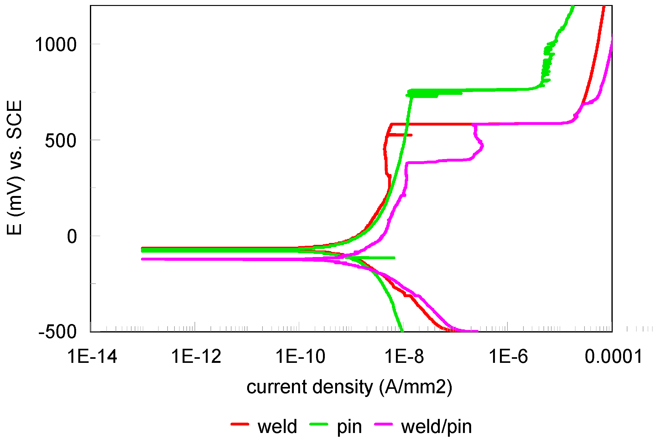
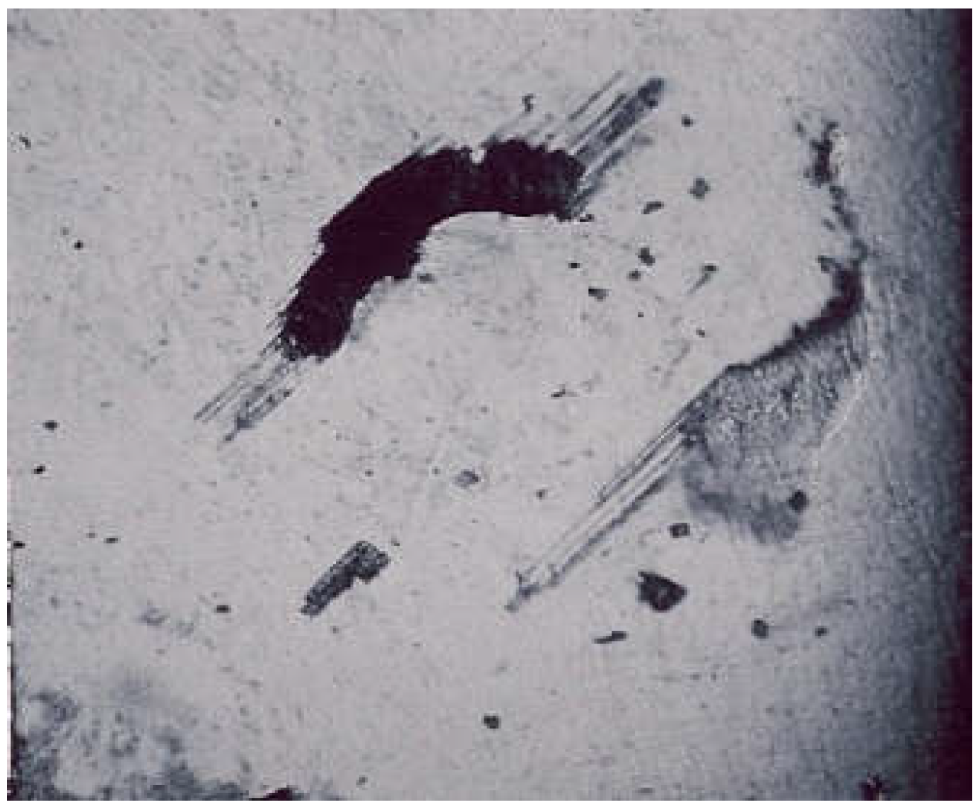
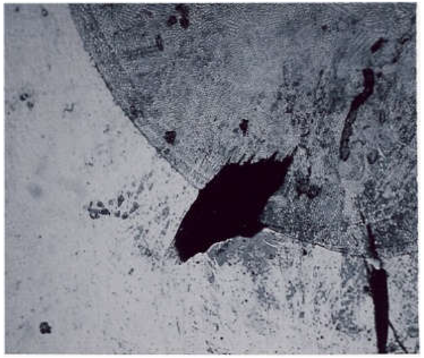
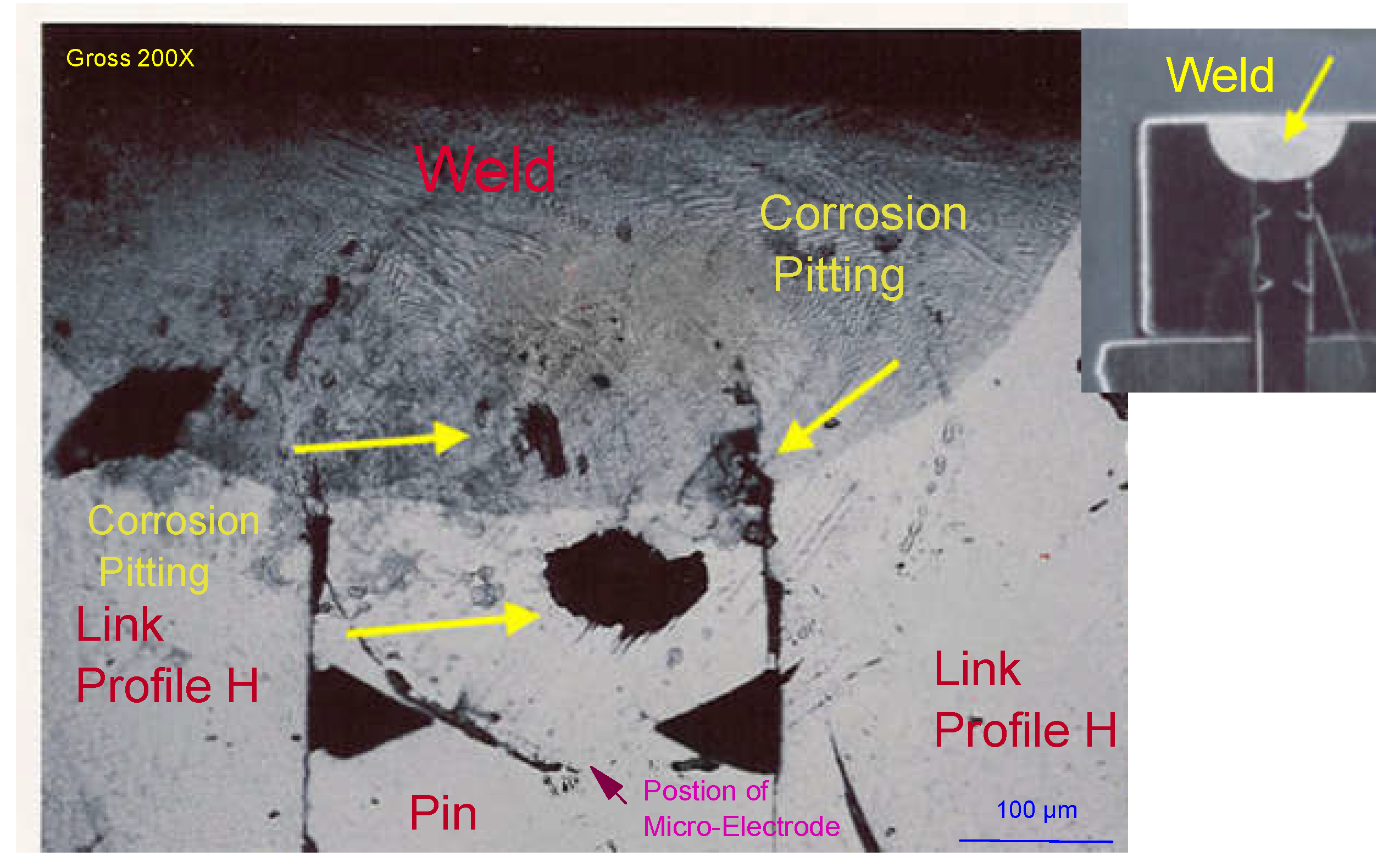
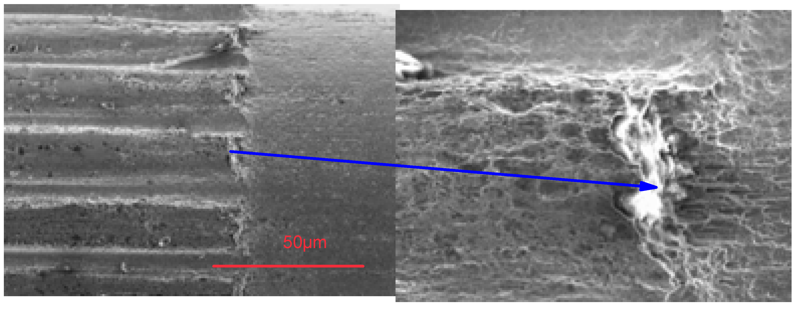
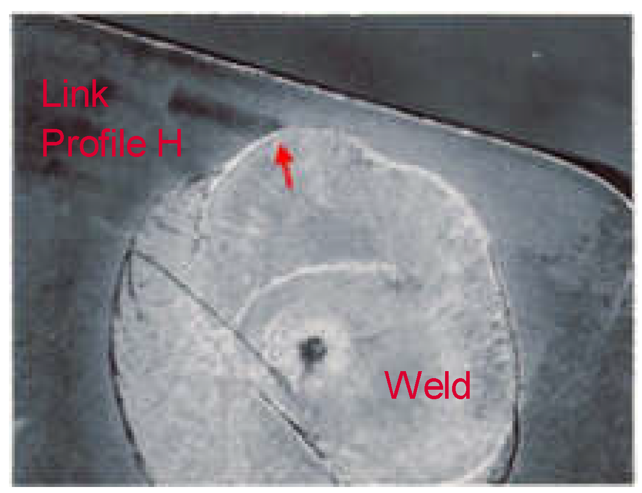
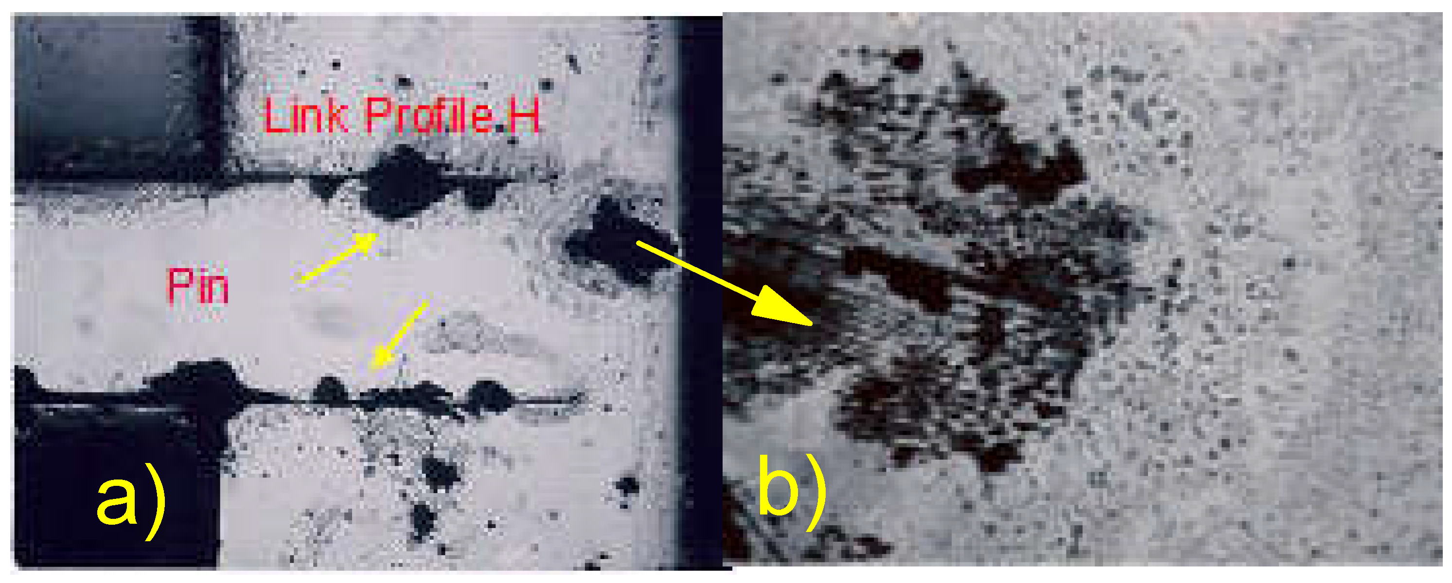
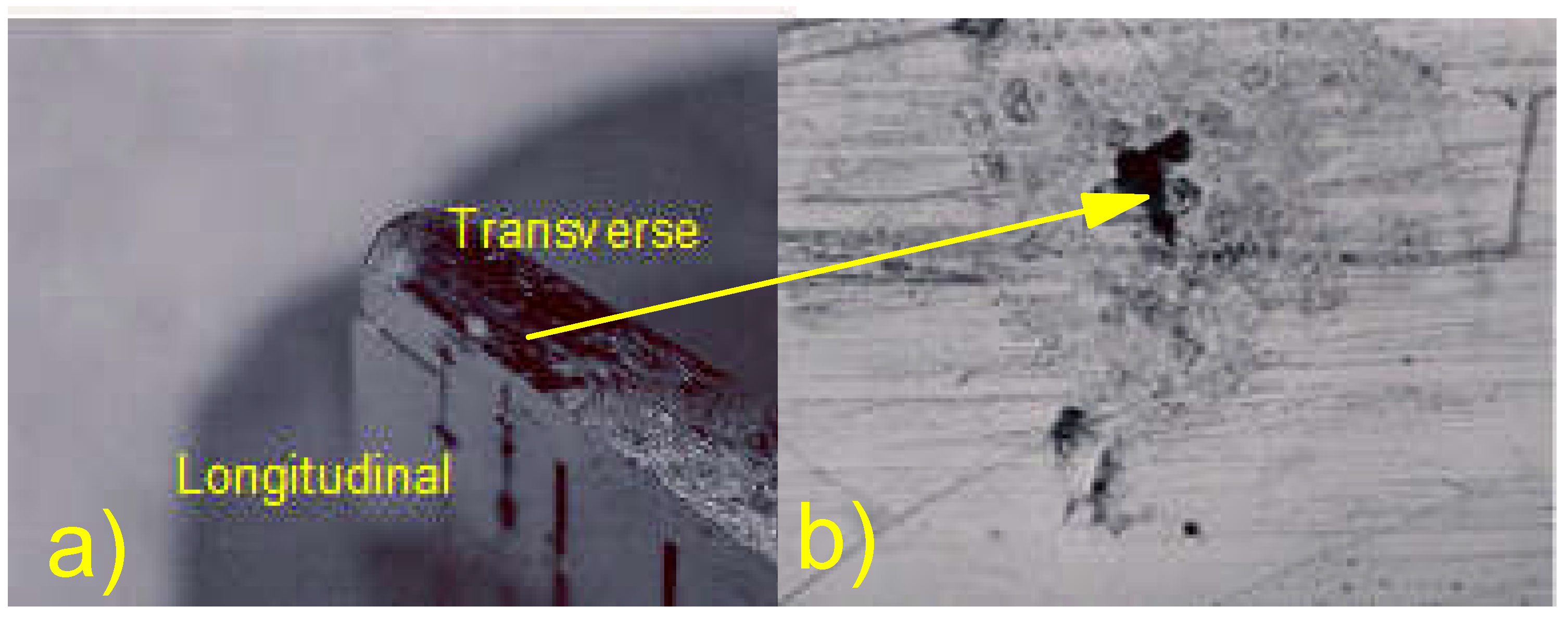
3.1. Corrosion Assessment of Welded Link/Pin Assemblies; the Microelectrode Technique

The polarization curves were drawn in a systematic way in the link, pin, laser weld areas and laser weld/link, laser weld/pin interfaces for the longitudinal surface (Figure 2a) and link, laser weld and laser weld/link interface for the transverse surface (Figure 2b). For a more precise representation of the corrosion behavior of the areas studied and for the reproducibility of the measurement technique, a large number of measurements were carried out. Therefore, the observations and comments were based on average values of current densities from the potentiodynamic scanning curves. In Figure 10, the scanning curves for the interface link/weld area of the transverse surface and the scanning curve of the average current values which were used for the interpretations are presented. The link is in 1.4441 grade steel, code #8. We measured two samples. The average value of the polarization curve obtained from two measurements is represented in green (Figure 10).
In Figure 11, we can see the positioning of the microelectrode in the welding/link interface on the transversal surface.

3.1.1. Measurements of the Transversal Surface

In Figure 12, two samples are shown, with the grade 1.4435, code #3. The average potentiodynamic scanning curves measured for the link H profile, weld and weld/link H profile interface areas are presented in Figure 12. It is noted that the weld area reveals a more noble behavior than the interface and the link. The electrochemical behavior of the interface was between that of the weld and that of the link, being closer to the electrochemical behavior of the weld. All the curves presented a plateau, specific to the localized pitting or crevice corrosion, in the current range of 10−8 to 10−5 A/mm2. On the other hand, the plateau height is different, 750 mV SCE for the weld, 500 mV SCE for the welding/link interface and 400 mV SCE for the link. This means that the weld displayed a good corrosion behavior and that the pitting process reaches a potential of around 750 mV. In general, dissimilar elements in galvanic couplings, in an artificial sweat medium and in contact with the skin, generate potential differences of around 400 mV.
The optical examination of the tested areas is presented in Figure 13 and Figure 14. When the microelectrode was placed at the weld/link interface, the corrosion process preferentially started at the interface (Figure 13 and Figure 14).
It should also be mentioned that the scanning electron microscope (SEM) examination and the intergranular corrosion tests did not reveal any microcracks in the laser welded and link H profile areas tested. On the other hand, pitting corrosion is evaluated in Figure 15a,b.

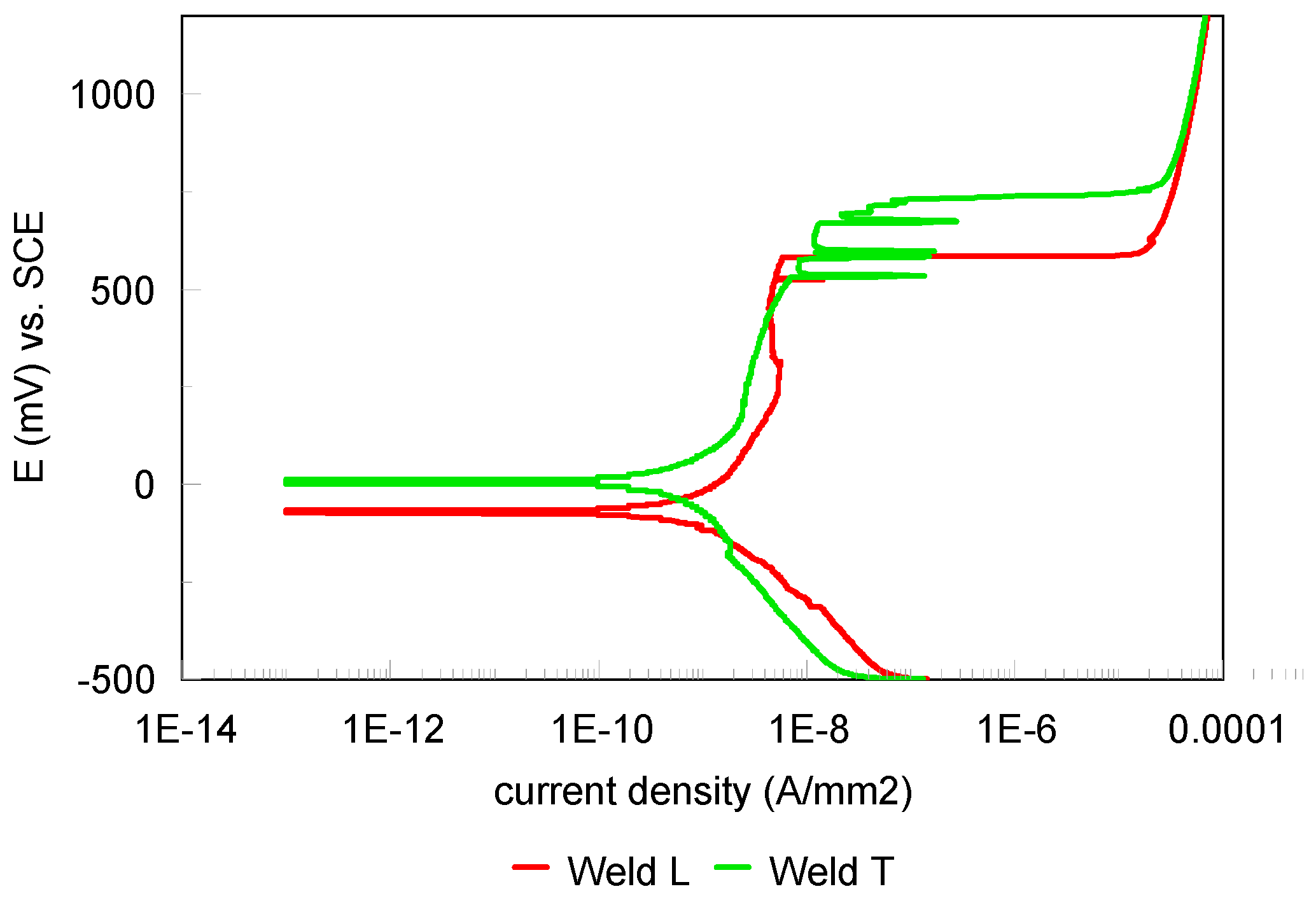
3.1.2. Measures in the Longitudinal Surface

The average potentiodynamic scanning curves for the longitudinal surface are represented in Figure 16 (the pin/interface/weld assembly) and Figure 17 (the link/interface/weld assembly), Sample #3.
The pins are made of 316LPM grade steel, DIN 1.4404 code #6.
Analysis of the scanning curves of the pin/weld system has also revealed current plateaus at different heights of potential, however, this time the pin is more noble than the weld. Contrariwise, in the case of the link/weld system, the link exhibited poor behavior. The link/weld interface also displayed poor behavior. Pitting and crevice corrosion were generated in the microelectrode positioning zones. Evidence for poor behavior can also be noticed by looking at the SEM images in Figure 18 and Figure 19.
On the other hand, if comparing the corrosion behavior of the link in both directions of the assembly, an important difference was noticed, explained by the fact that the transverse surface, from the point of view of the microstructure, is in the longitudinal direction of the pin/link assembly.
It has been established that the transverse surface, from the point of view of the structure, is more sensitive than the longitudinal one. The good corrosion behavior of the pin can be explained in the same way: the pin is corroded on the longitudinal surface from the point of view of the microstructure [20].
When comparing the potentiodynamic scanning curves of the weld, in transverse and longitudinal directions (Figure 20), no significant difference of corrosion behavior was noticed.
The pitting of the pin/weld interfaces (Figure 21 and Figure 22) is confirmed by the potentiodynamic polarization curves (Figure 16).
The anodic current, measured as a function of the potential, shows a maximum which separates the so-called active domain (metal in direct contact with the electrolyte) from the so-called passive domain (metal covered with an oxide film). In order for a passive metal to show good corrosion behavior, its corrosion potential must therefore lie in the passive domain. If a metal which has undergone chemical passivation in an oxidizing medium is immersed in an electrolyte, the value of the corrosion potential Ecorr will be Ep < Ecorr < Eb, where Eb is the breakdown potential on the polarization curve and Ep the electrical potential in an open circuit, for a given time of sample immersion. If the passivation is carried out correctly, a scan in the cathodic area will not really influence the Ecorr and therefore, after returning to the active domain, the value of Ecorr will remain in the passive domain and will be positive. In other words, the stability of the passivation film will not be affected by a weak cathode scan.
Another aspect that should be taken into account are the varying sensitivities of austenitic steels in the same corrosive environment. Although steels undergo the same manufacturing process for a watch strap, the corrosion test evaluations highlight significant differences from one steel to another. We tested approximately thirty stainless steels in regard to corrosion by pitting and crevices [21] according to ASTM G48-11(2020) E1 [40]. Figure 23 presents the results of the ferric chloride tests for the steels in Table 1.
Pitting densities were calculated from the number of microcavities counted by class based on the size of the microcavity area: <20 µm2, 20–50 µm2, 50–150 µm2, 150–500 µm2, 500–1000 µm2 and >1000 µm2 using the Kontron KS 300 Version 1.2 [21] image analysis program. The assessment was carried out according to ASTM G46-9 [41].
If we take into consideration only the 316L steel grade #3, #4, #5, #6, #7 and #8, they reveal a very large difference in corrosion behavior in pitting, especially on the transverse surface. The explanation may be related to the presence of minor chemical elements (Cu, Ca, Mn, Si, Ti, N) and traces of pollutants in the steels’ composition. Thus, the presence of minor elements and traces can modify the behavior of steels in regard to corrosion by pitting and crevices.
The steels #8 DIN 1.4441 (316L Med) and #9 DIN 1.4539 (904L) present a very good resistance to the morphologies of pitting and crevice corrosion, as outlined in Figure 21. They are strongly alloyed into oxidizing metals and form a strong passive layer. Additionally, they are the product of a vacuum process of primary melting and remelting, which contributes a high level of inclusion cleanliness and reduces the risk of pitting.
Nowadays, watchmakers obtain shades of remelted steels designed for the manufacture of wristbands and other watch components.
Watch straps are subjected to localized corrosion, especially through pitting and crevice corrosion in a sulfide–chloride medium, and through extensive wear of the watch straps [42,43,44,45].

3.2. Stress Corrosion Investigation

Figure 24 and Figure 25 show the potentiostatic curves for the measurements before the fracture of the pin. The comparison of the curves has shown that the currents recorded for the last cycles are significantly higher in the link/driven pin assembly than in the link/welded pin assembly.
The fracture occurred after 45 cycles, in the case of the driven assembly, and after 154 cycles, in the case of the laser welded assembly (a ratio of 3.4 times) (Figure 26, Figure 27, Figure 28 and Figure 29).
The fracture mechanism of the pin/link assembly can be very different, depending on whether the pin is driven out or laser welded. In the case of laser welded pins, the penetration of the electrolyte into the empty spaces between the link hole and the pin triggers a localized crevice corrosion process which leads to a decrease in the pin diameter, due to degradation. However, it will take an extended amount time for the entire pin to degrade.
On the other hand, in the case of driven pins, the penetration of the electrolyte at the link/pin interface triggers a crevice corrosion process which results in the widening of the link hole and the degradation of the pin surface. Thus, it takes very little to loosen the assembly and to degrade it, as seen in Figure 27, Figure 28 and Figure 29.

3.3. The Tuccillo–Nielsen Test

Figure 30 and Figure 31 highlight crevice corrosion aspects at the smooth driven pin/link interface (H profile). It cannot be excluded that a galvanic cell feeds the crevice corrosion. Particularly, in Figure 31, it can be noticed that the pin is intact while the link part of the pin/link interface is dissolving. On the surface and between the links, there are no specific signs of corrosion. The smooth driven pin exhibits corrosion signs after disassembly (Figure 32).
This corrosion in Figure 33 is much less obvious than in the case of the link/pin interfaces (Figure 31 and Figure 32).

3.4. Assessment of Sensitization to Intergranular Corrosion

The Strauss test according to ASTM 262-15 [39] did not reveal intergranular corrosion, especially in proximity to the laser welds (Figure 34 and Figure 35). No cracks were observed in the weld and laser welding did not cause local sensitization to intergranular corrosion.
Note that the metallographic texture of the pin and the link were observed by optical microscopy.

3.5. Ferric Chloride (FeCl3) Pitting and Crevice Corrosion Test, ASTM G 48-11

ASTM G48-11 [40] utilizes a ferric chloride (FeCl3) test in order to classify stainless steels with regard to their resistance to pitting and/or crevice. The use of a ferric chloride solution is justified by the fact that the chloride ions are known for their important role in the phenomenon of pitting corrosion [46,47] and their wide distribution in the environment, in particular in the case of biological environments (0.15% of the mass of the human body).
Ferric cations are also taken into account when discussing the mechanism of pitting corrosion, especially during the propagation stage [48]. These observations have priorly been verified in different environments by [21].
After the ferric chloride test, the links (H profile) displayed numerous pits on the longitudinal surface (Figure 36). The pins, on the other hand, showed no signs of pitting corrosion (Figure 37). The pin/link interstices exhibited signs of crevice corrosion (Figure 37a,b) and the weld (Figure 35 and Figure 36) developed corrosion on the longitudinal surface. The part of the weld exhibited in Figure 36 is not in direct contact with the environment during wear. On the transverse surface, the at the weld/link interface, germination of a pitting corrosion process was observed (Figure 38a,b). These observations are explained by the orientation of the alloy’s texture. As the H profile presents, in the case of the link, in regard to the texture, the inversion of the transverse and longitudinal surfaces occurs. This, however, is not the case of the pin.
The results obtained from the tested watch straps confirm that the pitting densities in the transverse surfaces showed a higher perforation density compared to the longitudinal surface (Figure 23).

3.6. Nickel Release from Watch Straps

Nowadays, legal frameworks and guidelines regarding the use and control of chemical elements and compounds have been established in order to protect the global population. Thus, one of the main goals of these regulations is to minimize the risk of induced contact dermatitis and allergies (primary prevention), which in turn also ensures that certain clinical diseases are not caused. In situations where this goal is not met, it is imperative to limit the occurrence of allergic diseases (secondary prevention). With regard to metal allergens, only nickel and chromium have been subject to significant legal restrictions to limit allergies, notably in the European Union, USA, Canada, Latin America and Asia (China, Japan and Korea).
Nickel allergy is the most widespread of all contact allergies. Concerning the European population, the prevalence of nickel allergy is 10%–15% of adult females and 1%–3% of adult males [2,22]. Thirty percent of nickel-sensitive people in the general population develop hand eczema. Teenagers and young adults tend to have a higher prevalence due to frequent body piercing. In Europe, for objects containing nickel which are intended for permanent contact with skin, Directive 94/27/EC imposed a ban if the rate of nickel release exceeds 0.5 µg/cm2/week [49,50,51,52].
Thus, the risk of inducing metal contact allergies is considered high if the steel’s qualities do not correspond to the requirements of manufacturers. It is important to note that the toxicological responsibility for the items falls on the manufacturer.
The quantities of nickel released are correlated with the operations involved in the manufacturing processes. Table 2 There is a very significant difference in the quantities of Ni released, in relation to the chemical composition of steels, which depends on the steelmaker. Heat processing results in a reduction of the nickel release rates. The surface state has little influence. On the other hand, the hardening processes strongly influence the quantity of nickel that is released. The increase in hardness greatly decreases the corrosion resistance and increases the amount of nickel released.
Another factor which strongly influences the amount of nickel released is the inclusion state and the existence of secondary phases in the structure of steels. Subcontractors are generally aware of these influencing factors and therefore typically require that the manufacturing process strictly follows guidelines and specifications.
For the construction of the bracelets, it will be necessary to approach technology transfer of innovative processes and techniques in the watch industry between the main players involved in development and production, such as watchmakers, the steel industry and applied science entities.
This transfer would largely refer to novel materials, enhanced micromechanics processes (manufacture of components), robotization within the production chain and assembly line, microwelding, marking [53] and maximized protection of the watch wearer and of skin contact. Regarding the latter, there is practically very limited information on the subject in the scientific literature, as public health is a very complex and macrofocused field. In the context of the watch industry, technology transfer attempts can fail overall since they give rise to a large number of industrial and commercial competitors. They are not expected to succeed in limiting the transfer of the basic knowledge to watchmakers but, instead, generate a novel competing industrial sector, which in turn reveals the internal divisions of a country’s watch industry [54].
In Table 3, we present the nickel release results on bracelet links, according to EN 1811. These links were obtained from the bracelets that we dismantled, thus one part was tested for corrosion and the other part in the tests of release. The results shown represent the average values of four extractions for each steel grade.

4. Conclusions

A set number of corrosion evaluation tests have been used in order to specifically assess the corrosion morphologies likely to appear in this type of assembly. The tests were performed on links of the finished bracelets that are in circulation on the market.
The laser welded link/pin assembly represents a step forward in terms of technical progress in the field of watchmaking and watch component production. It has therefore been interesting to compare it with the usual techniques by means of testing and experimentation.
It is recommended that the welds, which are usually sensitive elements, are in the cathode position. Thus, the risk of provoking a localized corrosion phenomenon (pitting, crevice, intergranular), powered by a galvanic battery and nickel release, remains low.
The stress corrosion test has shown a resistance to crevice corrosion of 3.4 times higher for the welded pins compared to the driven pins.
The idea of manufacturing an assembly of laser welded pins on an H profile has been proven favorable from the point of view of corrosion resistance.
According to the results obtained from this study, certain grades of steel cannot be used in the manufacture of wristbands of wristwatches.
If one takes into consideration the results of nickel release (acceptable at 0.5 µg/cm−2 week−1) for the eight grades of 316L steels, there is a rather large dispersion of the results. Bracelets do not have the same manufacturing source and were likely machined in the transverse face which is more sensitive to corrosion than the longitudinal face.
The passive layer is nevertheless insufficient to ensure complete immunity in all cases to localized corrosion encountered during wear. In consequence, subcontractors should demand that steelmakers produce a highly corrosion-resistant steel and that they strictly follow guidelines and specifications throughout the manufacturing process.

Funding

This research received no external funding.

Institutional Review Board Statement

Not applicable.

Informed Consent Statement

Not applicable.

Data Availability Statement

Not applicable.

Conflicts of Interest

The author declares no conflict of interest.

References

  1. Streicher, M.A. Austenitic and ferritic stainless steels. In Uhlig’s Corrosion Handbook, 3rd ed.; Winston Revie, R., Ed.; Revised by Grubb, J.F.; Wiley: Hoboken, NJ, USA, 2011; pp. 657–694. [Google Scholar]
  2. Annex XVII REACH. Available online: https://echa.europa.eu/documents/10162/5dea96fd-1db4-4b64-1572-19858939d8fd (accessed on 7 December 2022).
  3. Ha, H.-Y.; Lee, T.-H.; Bae, J.-H.; Chun, D.W. Molybdenum effects on pitting corrosion resistance of FeCrMnMoNC austenitic stainless steels. Metals 2018, 8, 653. [Google Scholar] [CrossRef] [Green Version]
  4. Newman, R.C. The dissolution and passivation kinetics of stainless alloys containing molybdenum—II. Dissolution kinetics in artificial pits. Corros. Sci. 1985, 25, 341–350. [Google Scholar] [CrossRef]
  5. Shames El Din, A.M.; Badran, M.M.; Khalil, S.E. Corrosion behaviour of manganese-containing stainless steels. II. Potentiodynamic measurements in H2SO4 solutions. Werkst. Korros. 1973, 24, 23–28. [Google Scholar] [CrossRef]
  6. Shames El Din, A.M.; Badran, M.M.; Khalil, S.E. Corrosion behaviour of manganese-containing stainless steels. III. Their susceptibi lity towards pitting corrosion. Werkst. Korros. 1973, 24, 290–295. [Google Scholar] [CrossRef]
  7. Janik-Czachor, M.; Lunarska, E.; Szklarska-Smialowvka, Z. Effect of nitrogen content in a 18Cr-5Ni-10Mn stainless steel on the pitting susceptibility in chloride solutions. Corrosion 1975, 31, 394–398. [Google Scholar] [CrossRef]
  8. Pardo, A.; Merino, M.C.; Coy, A.E.; Viejo, F.; Arrabal, R.; Matykina, E. Pitting corrosion behaviour of austenitic stainless steels–Combining effects of Mn and Mo additions. Corros. Sci. 2008, 50, 1796–1806. [Google Scholar] [CrossRef]
  9. Pardo, A.; Merino, M.C.; Coy, A.E.; Viejo, F.; Arrabal, R.; Matykina, E. Effect of Mo and Mn additions on the corrosion behavior of AISI 304 and 316 stainless steels in H2SO4. Corros. Sci. 2008, 50, 780–794. [Google Scholar] [CrossRef]
  10. Lunarska, E.; Szklarska-Smialowska, Z.; Janik-Czachor, M. Susceptibility of Cr-Ni-Mn stainless steels to pitting in chloride solutions. Corrosion 1975, 31, 231–234. [Google Scholar] [CrossRef]
  11. Ha, H.Y.; Jang, J.H.; Lee, T.H.; Won, C.; Lee, C.H.; Moon, J.; Lee, C.G. Investigation of the localized corrosion and passive behavior of type 304 stainless steels with 0.2–1.8 wt% B. Materials 2018, 11, 2097. [Google Scholar] [CrossRef] [Green Version]
  12. Technical Specification of AISI 304L Steel. Available online: https://pxgroup.com/sites/default/files/304-L-1.4306.pdf (accessed on 7 December 2022).
  13. Technical Specification of AISI 316L Steel. Available online: https://pxgroup.com/sites/default/files/316-L-1.4435.pdf (accessed on 7 December 2022).
  14. Technical Specification of AISI 316L Medical Steel. Available online: https://pxgroup.com/sites/default/files/316Lmdical.pdf (accessed on 7 December 2022).
  15. Technical Specification of AISI 904L Steel. Available online: https://pxgroup.com/sites/default/files/904-L_0.pdf (accessed on 7 December 2022).
  16. Kruger, J. Passivity. In Uhlig’s Corrosion Handbook, 3rd ed.; Winston Revie, R., Ed.; Wiley: Hoboken, NJ, USA, 2011; pp. 151–157. [Google Scholar]
  17. South, A.; Paudouard, P.; Marcus, P. The role of nitrogen in the passivity of austenitic stainless steels. Corros. Sci. 1994, 36, 1825–1834. [Google Scholar]
  18. Wang, Z.; Paschalidou, E.-M.; Seyeux, A.; Zanna, A.; Maurice, V.; Marcus, P. Mechanisms of Cr and Mo enrichments in the passive oxide film on 316L austenitic stainless steel. Front. Mater. 2019, 24, 232. [Google Scholar] [CrossRef]
  19. Metikoš-Huković, M.; Babić, R.; Grubač, Z.; Petrović, N.Z.; Lajçi, N. High corrosion resistance of austenitic stainless steel alloyed with nitrogen in an acid solution. Corros. Sci. 2011, 6, 2176–2183. [Google Scholar] [CrossRef]
  20. Reclaru, L.; Lüthy, H.; Ziegenhagen, R.; Eschler, P.-Y.; Blatter, A. Anisotropy of nickel release and corrosion in austenitic stainless steels. Acta Biomater. 2008, 4, 680–685. [Google Scholar] [CrossRef] [PubMed]
  21. Reclaru, L.; Ziegenhagen, R.; Eschler, P.-Y.; Blatter, A.; Lüthy, H. Effects of Crystallographic Orientation of Stainless Steels on Pitting and Crevice Corrosion and Nickel Release; New Research on Biomaterials; Bloomington, E., Denzel, R., Eds.; Publishers Nova Science Publisher Inc.: Hauppauge, NY, USA, 2007; pp. 237–279. Available online: http://www.novapublishers.org/catalog/produc (accessed on 7 December 2022).
  22. Baker, M. European Standards Developed in Support of the European Union Nickel Directive, Metal Allergy; pp. 23–29. Available online: https://link.springer.com/book/10.1007%2F978-3-319-58503-1?page=1#toc (accessed on 7 December 2022).
  23. Nickel Directive: European Parliament and Council directive 94/27/EC of 30 June 1994. Amending for the 12th time Directive 76/769/EEC on the Approximation of the Laws, Regulations and Administrative Provisions of the Member States Relating to Restrictions on the Marketing and Use of Certain Dangerous Substances and Preparations. Off. J. Eur. Commun. 1994, 188, 1–2.
  24. Commission Communication in the Framework of the Implementation of Regulation (EC) No 1907/2006 of the European Parliament and of the Council Concerning the Registration, Evaluation, Authorization and Restriction of Chemicals (REACH). Off J. Euro. Union. 2016, C14, 110.
  25. Fleischmann, M.; Pattison, J.; Thirsk, H.R. Electrocrystallization of thin films of thallous chloride on thallium amalgam Trans. Faraday Soc. 1965, 61, 1256–1269. [Google Scholar] [CrossRef]
  26. Foroulis, Z.A.; Uhlig, H.H. Effect of cold-work on corrosion of iron and steel in hydrochloric acid. J. Electrochem. Soc. 1964, 111, 522–528. [Google Scholar] [CrossRef]
  27. Kabanov, B.N.; Leikis, Z.I. Untersuchung der Passivität von Metallen durch Messung der Elektrodenimpedanz bei hohen. Frequenzen. Z. Elektrochem. 1958, 62, 660–663. [Google Scholar]
  28. Kolotyrkin, M.Y. Electrochemical behaviour and anodic passivity mechanism of certain metals in electrolyte solutions. Z. Elektrochem. 1958, 62, 664–669. [Google Scholar]
  29. Frankenthal, R.P. On the passivity of iron-chromium alloys: II. The activation potential. J. Electrochem. Soc. 1969, 116, 580–585. [Google Scholar] [CrossRef]
  30. Müller, W.J. Die Bedeckungstheorie der Passivität der Metalle und ihre experimentelle Begründung. Verlag Chemie, Berlin 1933 sau. J. Phys. Chem. 1934, 38, 132. [Google Scholar] [CrossRef]
  31. Lukac, C.; Lumsden, J.B.; Smialowska, S.; Staehle, R.W. Effects of temperature on the kinetics of passive film growth on iron. J. Electrochem. Soc. 1975, 122, 1571–1580. [Google Scholar] [CrossRef]
  32. Bockris, J.O.M.; Genshaw, M.A.; Brusic, V.; Wroblowa, H. The mechanism of the passivation of iron in neutral solutions: An ellipsometric and coulometric investigation. Electrochim. Acta 1971, 16, 1859–1894. [Google Scholar] [CrossRef]
  33. Bohni, H. Localized corrosion of passive metals 157–171. In Uhlig’s Corrosion Handbook, 3rd ed.; Winston Revie, R., Ed.; Wiley: Hoboken, NJ, USA, 2011. [Google Scholar]
  34. Lizlovs, E.A.; Bond, A.P. Anodic polarization behavior of high-purity 13 and 18% Cr stainless steels bond. J. Electrochem. Soc. 1975, 122, 719–723. [Google Scholar] [CrossRef]
  35. Uhlig, H.H.; Revie, G.H.T. Corrosion and Corrosion Control, 3rd ed.; Wiley-Interscience: New York, NY, USA, 1985. [Google Scholar]
  36. Crow, W.B.; Myers, J.R.; Marvin, B.D. Anodic polarization behaviour of Ni–Al alloys in sulfuric acid solutions. Corrosion 1971, 27, 459–465. [Google Scholar] [CrossRef]
  37. Tomashov, N.D.; Chernova, G.P.; Ruscol, Y.S.; Ayuyan, G.A. The passivation of alloys on titanium bases. Electrochim. Acta 1974, 19, 159–172. [Google Scholar] [CrossRef]
  38. ASTM F746-87; Standard Test Method for Pitting or Crevice Corrosion of Metallic Surgical Implant Materials. American National Standards Institute: Washington, DC, USA, 2009.
  39. Tuccillo, J.J.; Nielsen, J.P. Observations of onset of sulfide tarnish on gold-base alloys. J. Prosthet. Dent. 1971, 25, 629–637. [Google Scholar] [CrossRef]
  40. ASTM A262-15; Standard Practices for Detecting Susceptibility to Intergranular Attack in Austenitic Stainless Steels. ASTM International: West Conshohocken, PA, USA, 2015. Available online: www.astm.org (accessed on 2 May 2020).
  41. ASTM G48-11; Standard Test Methods for Pitting and Crevice Corrosion Resistance of Stainless Steels and Related Alloys by Use of Ferric Chloride Solution. ASTM International: West Conshohocken, PA, USA, 2015.
  42. ASTM 46-94; Standard Guide for Examination and Evaluation of Pitting Corrosion. American National Standards Institute: Washington, DC, USA, 2018.
  43. ASTM B117; Standard Practice for Operating Salt Spray (Fog) Apparatus. ASTM International: West Conshohocken, PA, USA, 2003.
  44. ISO 9227:2017; Essais de Corrosion en Atmosphères Artificielles—Essais aux Brouillards Salins. ISO: Geneva, Switzerland, 2022.
  45. NIHS 96-50; Procédé pour Estimer la Résistance aux Agents Chimiques et Climatiques d’un Habillage Horloger. Fédération de L’industrie Horlogère Suisse FH: Biel, Switzerland, 2013.
  46. EN 1811; A1: Reference Test Method for Release of Nickel from all Post Assemblies Which are Inserted into Pierced Parts of the Human Body and Articles Intended to Come into Direct and Prolonged Contact with the Skin (Includes Amendment A1:2015). iTeh Standards: Newark, DE, USA, 2015.
  47. Hoar, T.P.; Mears, D.C. Corrosion-resistant alloys in chloride solutions: Materials for surgical implants. Proc. R. Soc. Lond. 1966, 294, 486–510. [Google Scholar]
  48. Zabel, D.D.; Brouwn, S.A.; Merritt, K.; Payer, I.H. AES analysis of stainless steel corroded in saline, in serum and in vivo. J Biomed. Mater Res. 1988, 22, 31–44. [Google Scholar] [CrossRef]
  49. Turnbull, A. The solution composition and electrode potential in pits, crevices and cracks. Corros. Sci. 1983, 23, 833–870. [Google Scholar] [CrossRef]
  50. Kate, H.; David, B. Metal Exposure Regulations and Their Effect on Allergy Prevention in Metal Allergy; Chen, J.K., Thyssen, J.P., Eds.; Springer: Berlin, Germany, 2018; pp. 39–54. [Google Scholar] [CrossRef]
  51. Liden, C. Nickel in jewelry and associated products. Contact Dermat. 1992, 26, 73–75. [Google Scholar] [CrossRef] [PubMed]
  52. Belsito, D.V. The diagnostic evaluation, treatment, and prevention of allergic contact dermatitis in the new millennium. J. Allergy Clin. Immunol. 2000, 105, 409–420. [Google Scholar] [CrossRef] [PubMed]
  53. Schafer, T.; Bohler, E.; Ruhdorfer, S.; Weigl, L.; Wessner, D.; Filipiak, B.; Wichmann, H.E.; Ring, J. Epidemiology of contact allergy in adults. Allergy 2001, 56, 1192–1196. [Google Scholar] [CrossRef] [PubMed]
  54. Landes, D.S. Revolution in time. In Clocks and the Making of the Modern World; Viking: London, UK, 2000; 518p. [Google Scholar]
Figure 1. Strands of a watch strap.
Coatings 13 00018 g001
Figure 2. (a) Longitudinal link/pin assemblies; (b) transverse link/pin assemblies.
Coatings 13 00018 g002
Figure 3. (a) Microelectrode; (b) the schematic representation of the microelectrode measurement system (RE: reference electrode).
Coatings 13 00018 g003
Figure 4. The microelectrode protected by the Faraday and Helmholtz cages.
Coatings 13 00018 g004
Figure 5. Sample fixed in the stress corrosion holders.
Coatings 13 00018 g005
Figure 6. The electrochemical stress corrosion cell.
Coatings 13 00018 g006
Figure 7. The electrochemical stress corrosion cell and the hanging weight system.
Coatings 13 00018 g007
Figure 8. The arrows indicate the area targeted by the electrochemical stress corrosion test. Optical examination, magnification 10×.
Coatings 13 00018 g008
Figure 9. The Tuccillo–Nielsen system.
Coatings 13 00018 g009
Figure 10. The potentiodynamic polarization curves measured for the interface link/weld area of the transverse surface and the average curve obtained from the experimental curves. Sample #8.
Coatings 13 00018 g010
Figure 11. Electrochemical measurement at the laser welding/link H profile interface of the transversal surface (scale = 100 microns). Sample #8.
Coatings 13 00018 g011
Figure 12. The average potentiodynamic polarization curves for the weld, link and link/weld interface areas. Sample #3.
Coatings 13 00018 g012
Figure 13. Pitting corrosion of the link/weld interface of the transversal surface in Test 1. Optical examination, magnification 40×, Sample #3.
Coatings 13 00018 g013
Figure 14. Pitting corrosion of the link/weld interface of the transversal surface in Test 2. Optical examination, magnification 40×. Sample #3.
Coatings 13 00018 g014
Figure 15. (a) Transversal surface of the weld. Corrosion pitting within the weld. Scale = 50 µm, Sample #3. (b) Transversal surface of the link H profile. Corrosion pitting within the link. Scale = 50 µm, Sample #3.
Coatings 13 00018 g015
Figure 16. Average potentiodynamic polarization curves of the longitudinal surface weld, pin and the weld/pin interface. Sample #3.
Coatings 13 00018 g016
Figure 17. Average potentiodynamic polarization curves of the longitudinal surface (weld, link and weld/link interface). Sample #3.
Coatings 13 00018 g017
Figure 18. Microelectrode positioned on the link, longitudinal surface. Optical examination, magnification 20×, Sample #6.
Coatings 13 00018 g018
Figure 19. Microelectrode positioned at the link/pin interface. Optical examination, magnification 20×, Sample #6.
Coatings 13 00018 g019
Figure 20. Comparative presentation of the average scanning curves of the weld in the longitudinal (L) and transverse (T) directions of the assembly. Sample #8.
Coatings 13 00018 g020
Figure 21. Microelectode positioned in weld/link/pin area, longitudinal surface. Optical examination, magnification 40×, Sample #4.
Coatings 13 00018 g021
Figure 22. Microelectrode positioned in the weld area, longitudinal surface. Sample #4.
Coatings 13 00018 g022
Figure 23. Pitting test in the transverse and longitudinal faces for various grades of nickel alloys. Test medium FeCl3 0.5M at 50 °C, 2 h.
Coatings 13 00018 g023
Figure 24. Potentiostatic polarization curves before the fracture of the pin, in the case of the link/welded pin assembly. Sample #4.
Coatings 13 00018 g024
Figure 25. Potentiostatic polarization curves before the fracture of the pin, in the case of the link/driven pin assembly. Sample #7.
Coatings 13 00018 g025
Figure 26. Fracture of the laser welded pin after 154 cycles. Optical examination, magnification 10×, Sample #6.
Coatings 13 00018 g026
Figure 27. Unbroken part of the laser welded pin assembly. Crevice corrosion. Scale = 50 µm. Sample #4.
Coatings 13 00018 g027
Figure 28. Corrosion around the flushing/hunting hole after 45 cycles (fracture). Scale = 100 µm. Sample #7.
Coatings 13 00018 g028
Figure 29. Corrosion in the grooves of the knurled pin after 45 cycles. Scale = 100 µm. Sample #7.
Coatings 13 00018 g029
Figure 30. Corrosion aspect at the link/smooth driven pin interface. Optical examination, magnification 10×. Optical examination, magnification 5×. Link sample #7 and pin sample #3.
Coatings 13 00018 g030
Figure 31. Crevice corrosion at the link/driven pin interface. Optical examination, magnification 20×. Link sample #7 and pin sample #3.
Coatings 13 00018 g031
Figure 32. Pin removed after the Tuccillo–Nielsen test. Scale = 50 µm. Link sample #7 and pin sample #3.
Coatings 13 00018 g032
Figure 33. Corrosion at the laser weld/link interface. Optical examination, magnification 5×. Link sample #4 and pin sample #3.
Coatings 13 00018 g033
Figure 34. Weld/link and weld/pin interfaces after the Strauss test. Longitudinal surface. Optical examination, magnification 40×. Link sample #4 and pin sample #3.
Coatings 13 00018 g034
Figure 35. Weld/link and weld/pin interfaces after the Strauss test. Transversal surface. Optical examination, magnification 40×. Link sample #4 and pin sample #3.
Coatings 13 00018 g035
Figure 36. Pitting corrosion in the longitudinal surface of the link (H profile). Optical examination, magnification 5×. Sample #5.
Coatings 13 00018 g036
Figure 37. (a). Link, pin and weld after the FeCl3 test. Longitudinal surface. Optical examination, magnification 10×. Link sample #5 and pin sample #3.; (b) Corrosion around the weld/link interface after the FeCl3 test. Transverse surface. Optical examination, magnification 20×. Link sample #5 and pin sample #3.
Coatings 13 00018 g037
Figure 38. (a). Corrosion in the area of the weld/link interface after the FeCl3 test. Transverse surface. Optical examination, magnification 10×. Sample #5.; (b) Corrosion in the area of the weld/link interface. Transverse face. Optical examination, magnification 20×. Sample #5.
Coatings 13 00018 g038
Table 1. The nominal chemical composition (%) of austenitic steels used in watch straps.
Code DINAISICSiMnPSCrMoNiOther
#11.4301304L<0.07<1.00<2.00<0.045<0.001517.0–19.5-8.0–10.5N < 0.11
#21.4306304L<0.030<1.50<1.50<0.035<0.02017.0–20.0-8.0–12.0N 0.10-0-20
#31.4435316L<0.030<1.00<2.00<0.045<0.02517.0–18.52.5–3.012.5–15.0-
#41.4435316L Ugima<0.030<1.00<2.00<0.045<0.03017.0–18.252.5–3.012.5–15.0N < 0.11
#51.4404316L Val<0.030<1.00<2.00<0.045<0.03016.5–18.52.0–2.510.0–13.0N < 0.11
#61.4404316L PM<0.03<1.00<2.00<0.045<0.01516.5–18.52.0–2.510.0–13.0
#71.4435316L SW<0.03<1.00<2.00<0.045<0.01517.0–19.02.5–3.012.5–15.0N < 0.011
#81.4441316L med.<0.030<1.00<2.00<0.025<0.01017.0–0.192.50–3.2013.0–15.5N < 0.10; Cu < 0.120
#91.4539904L<0.02<0.70<2.00<0.030<0.01519.0–21.04.00–5.0024.0–26.0Cu 1.00–2.00; N 0.04–0.15
Table 2. Factors influencing the amounts of nickel released during the manufacturing process.
ParameterEffectQuantity of Ni Released
Raw MaterialsVariable in Function of the LotCoatings 13 00018 i001Strong Dispersion
Heat Treatment100% H2
100% N2
Coatings 13 00018 i002Strong Decrease
Slight Decrease
Surface Rough, Polished, SatinyCoatings 13 00018 i003Slight Influence
Work HardeningStrain >10%Coatings 13 00018 i004Increase
StructureInclusion and Second PhaseCoatings 13 00018 i005Increase
Table 3. Nickel release according to EN 1811 standard.
CodeStandard DINStandard AISINickel Release [μg·cm−2·week−1]
#11.4301304L0.63
#21.4306304L0.36
#31.4435316L0.17
#41.4435316L Ugima0.15
#51.4404316L Val0.52
#61.4404316L PM0.37
#71.4435316L SW0.14
#81.4441316L Med0.09
#91.4539904L0.23
Disclaimer/Publisher’s Note: The statements, opinions and data contained in all publications are solely those of the individual author(s) and contributor(s) and not of MDPI and/or the editor(s). MDPI and/or the editor(s) disclaim responsibility for any injury to people or property resulting from any ideas, methods, instructions or products referred to in the content.

