
Experimental Study on Shear Performance of Post-Tensioning Prestressed Concrete Beams with Locally Corroded Steel Strands
Abstract
:1. Introduction
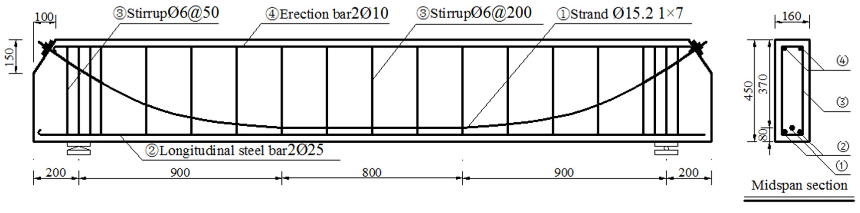
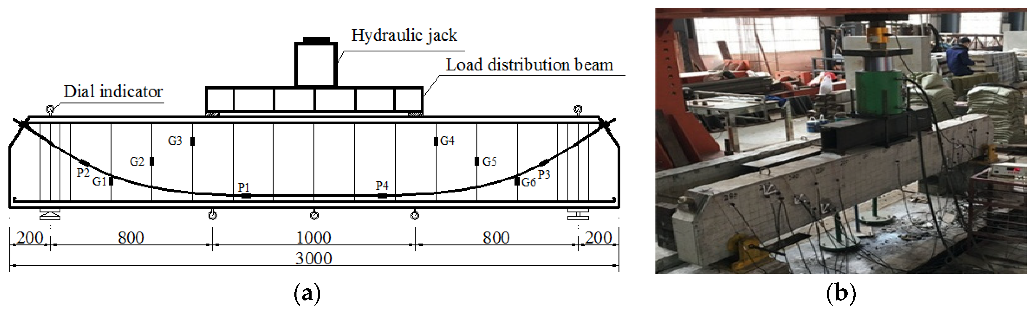
2. Test Profile
3. Shear Performance Analysis
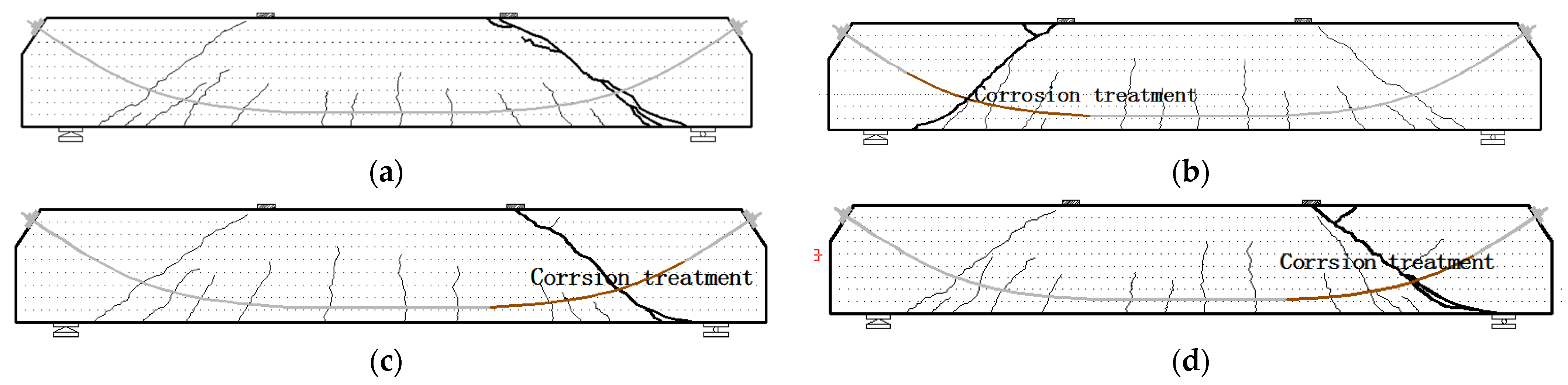
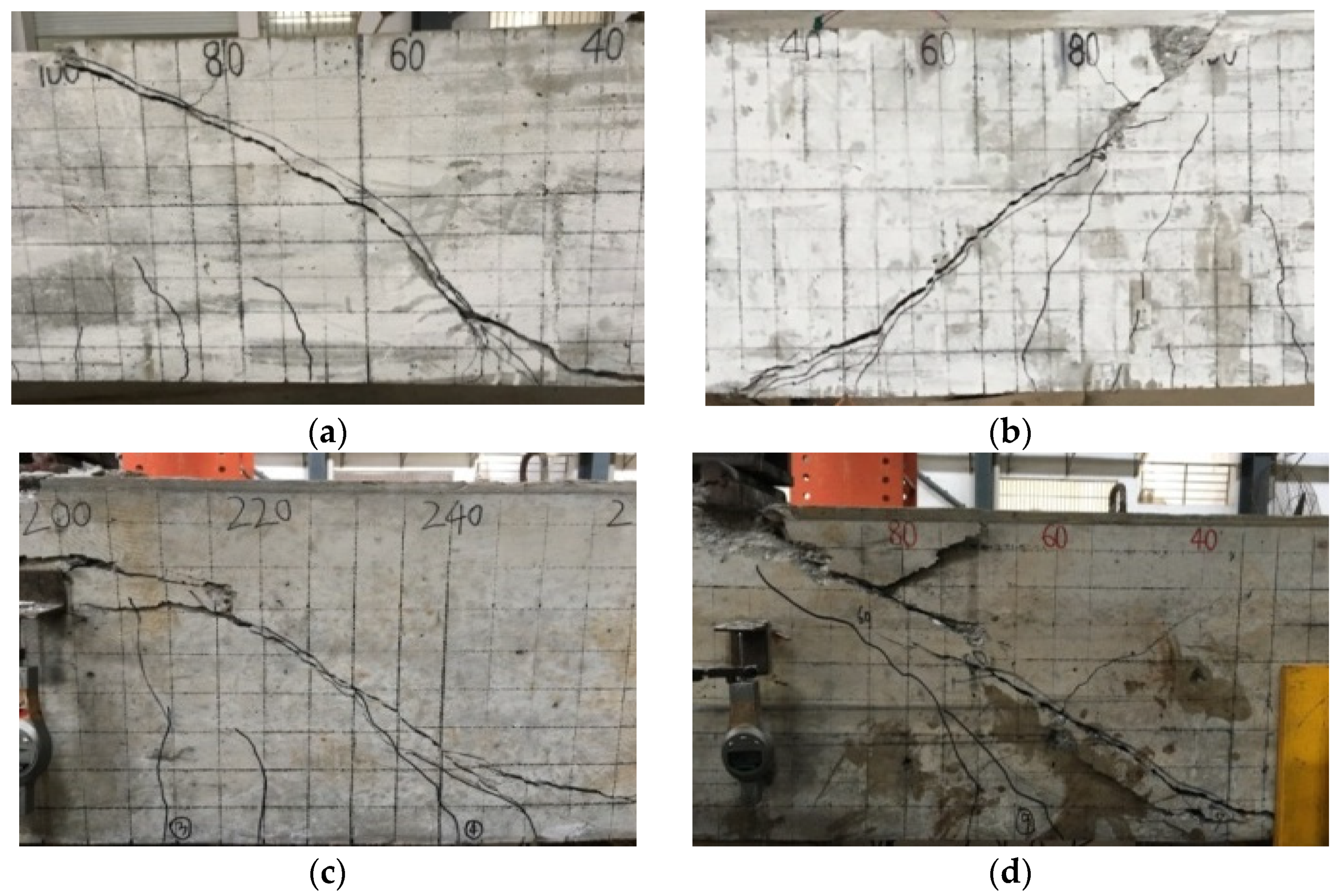
3.1. Crack Propagation
3.2. Failure Mode
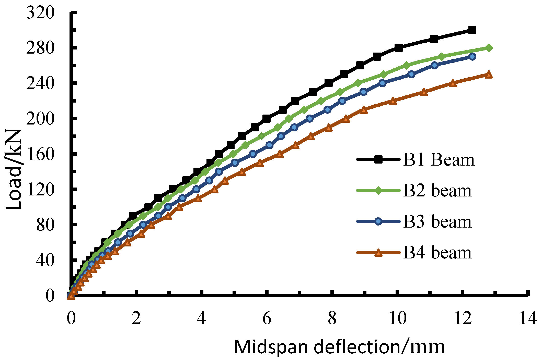
3.3. Deflection Analysis
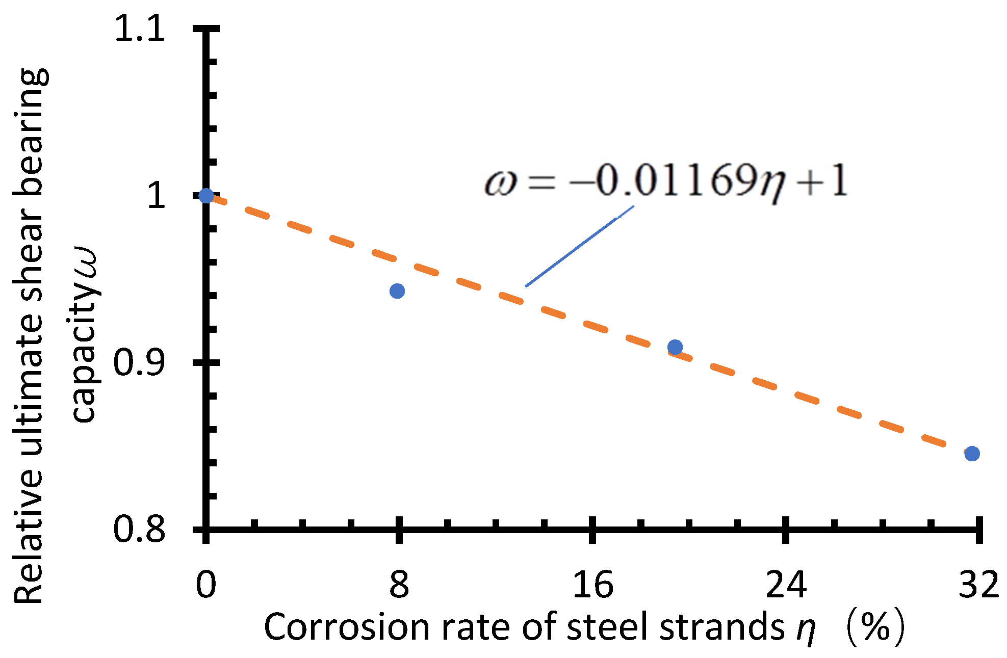
3.4. Ultimate Load
4. Calculation of Ultimate Shear Bearing Capacity
4.1. Simplified Computational Analysis of Shear Bearing Capacity
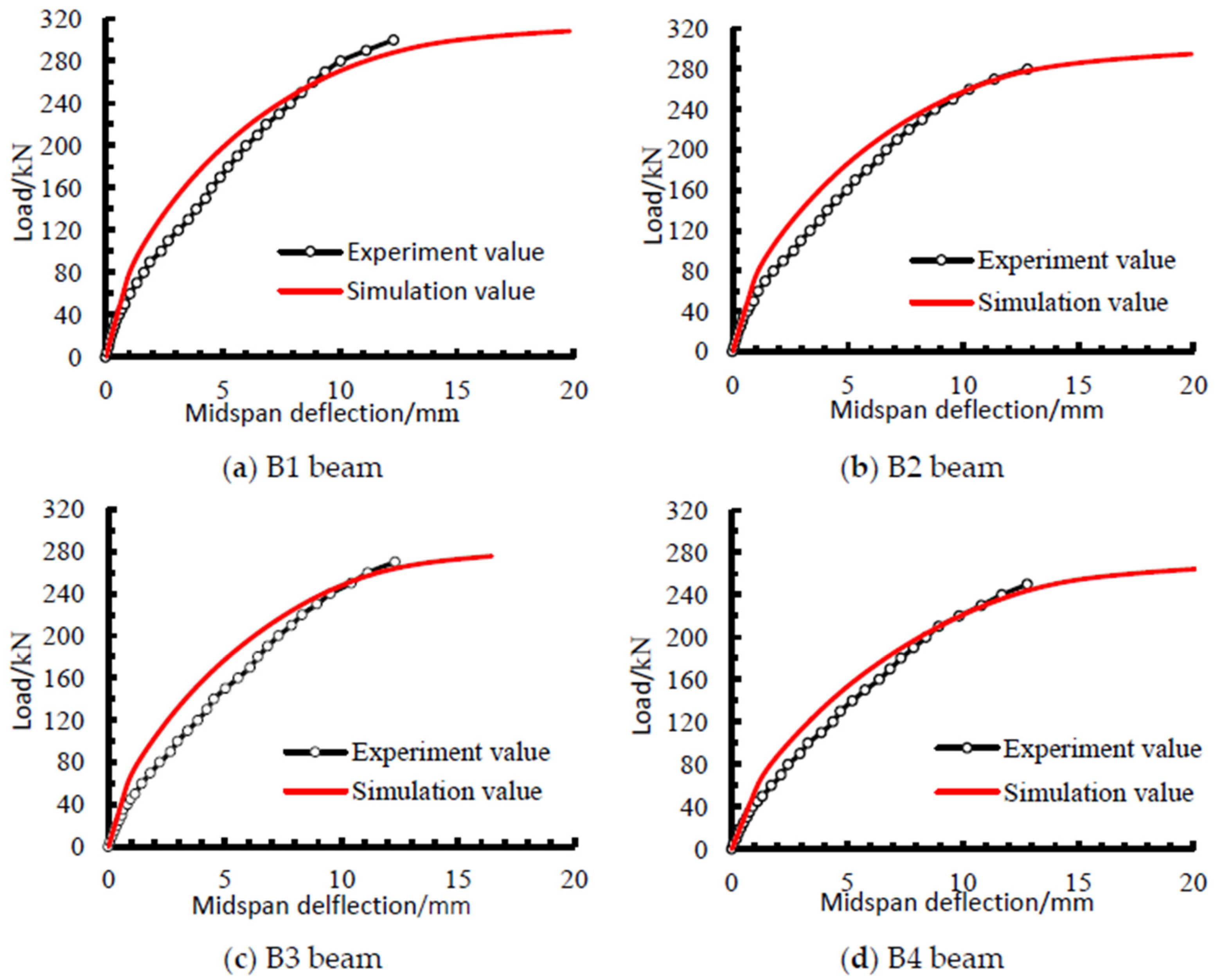
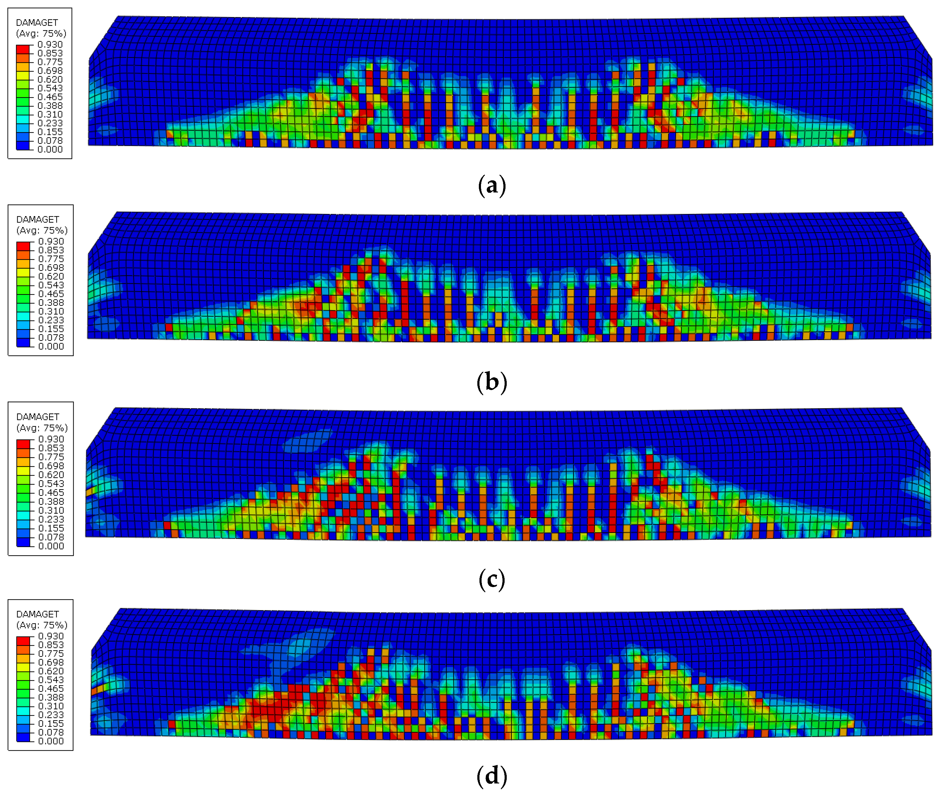
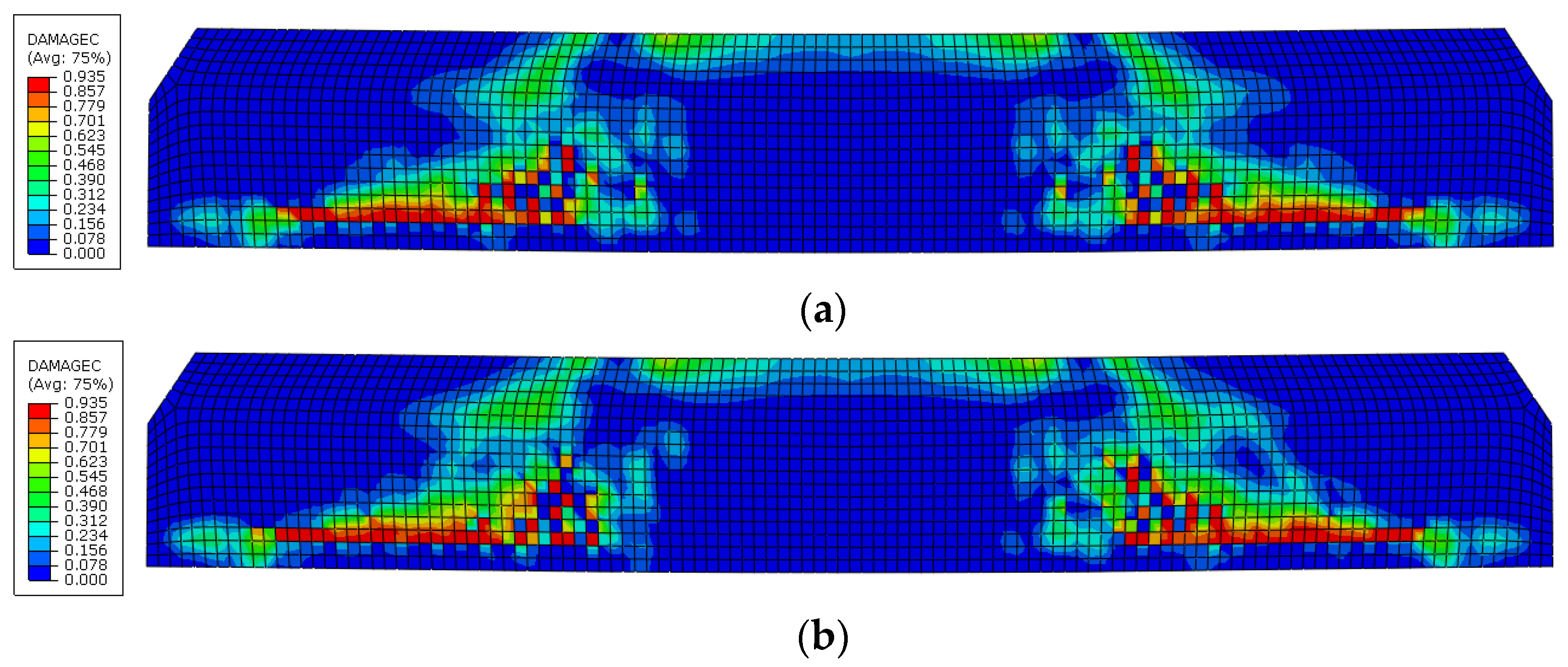
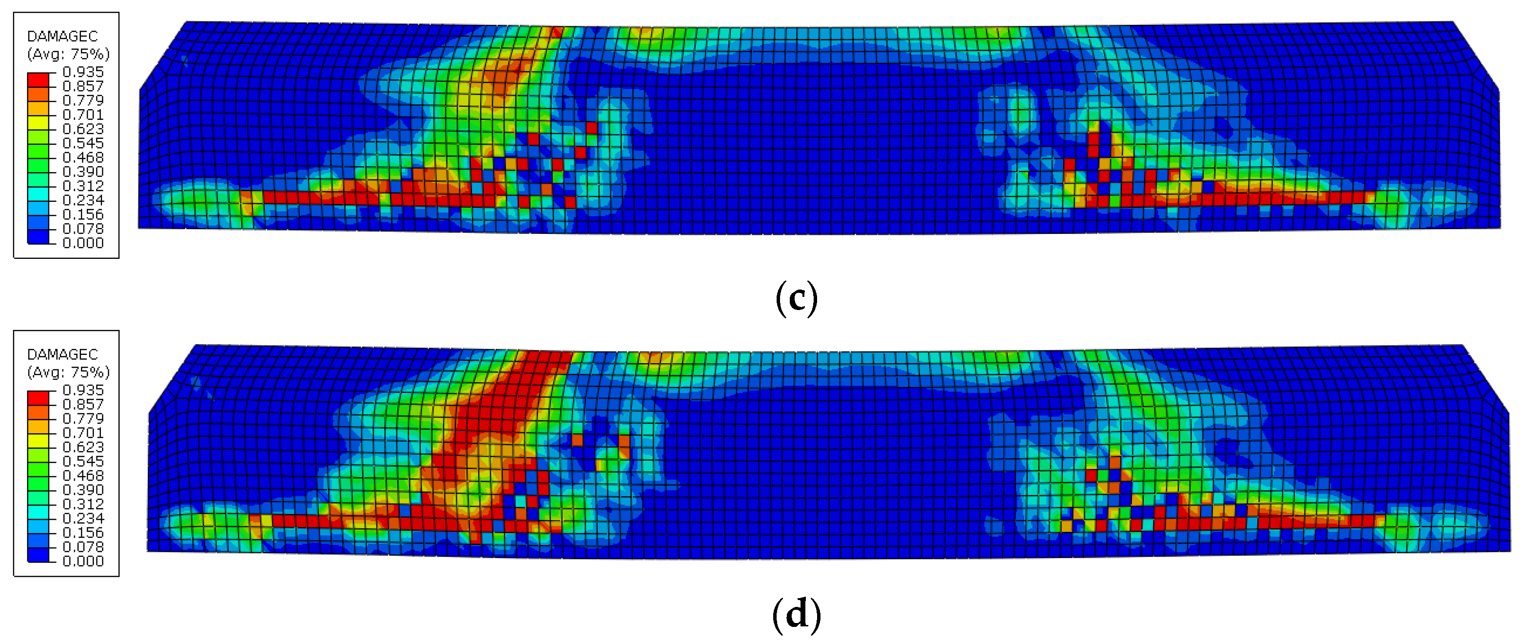
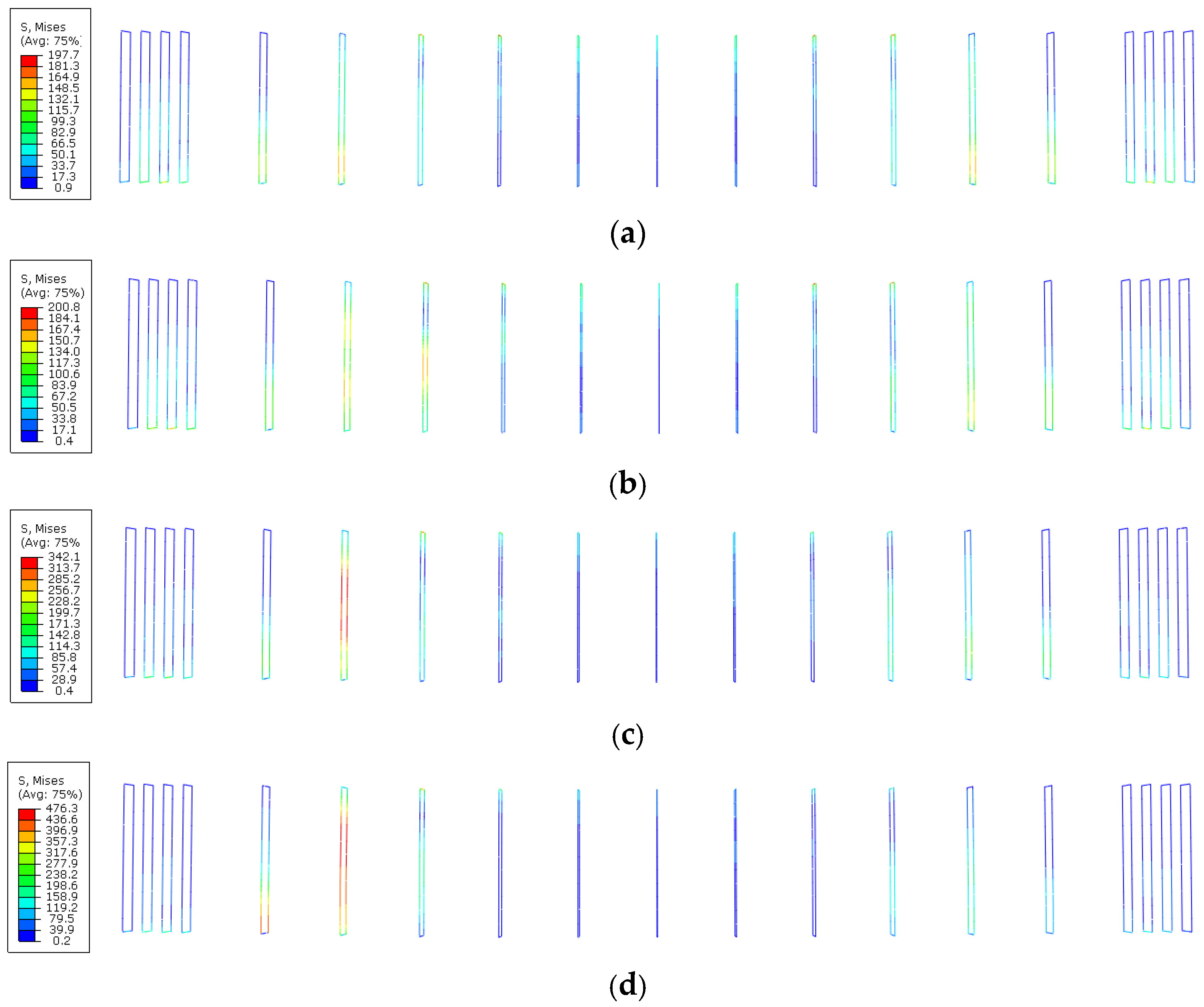
4.2. Numerical Simulation Analysis of Shear Performance
5. Conclusions
Author Contributions
Funding
Institutional Review Board Statement
Informed Consent Statement
Data Availability Statement
Acknowledgments
Conflicts of Interest
References
- Yang, Y.M.; Peng, J.X.; Liu, X.H.; Cai, C.S.; Zhang, J.R. Probability analysis of web cracking of corroded prestressed concrete box-girder bridges considering aleatory and epistemic uncertainties. Eng. Struct. 2020, 228, 111486. [Google Scholar] [CrossRef]
- Shen, X.W.; Wang, R.H. Mechanics Effect Analysis of Pre-tensioned and Post-tensioned Pre-stressed Concrete Simply-supported Box Beams on High-speed Railway. China Railw. Sci. 2004, 25, 100–104. [Google Scholar]
- Yang, Y.M.; Tang, H.; Wang, X.Z. Failure probability analysis of corroded RC structures considering the effect of spatial variability. Mag. Concrete Res. 2022. ahead of print. [Google Scholar] [CrossRef]
- Yang, Y.M.; Peng, J.X.; Cai, C.S.; Zhang, J.R. Improved interval evidence theory–based fuzzy AHP approach for comprehensive condition assessment of long-span PSC continuous box-girder bridges. J. Bridge Eng. 2019, 24, 04019113. [Google Scholar] [CrossRef]
- Peng, J.X.; Yang, Y.M.; Bian, H.B.; Zhang, J.R.; Wang, L. Optimisation of maintenance strategy of deteriorating bridges considering sustainability criteria. Struct. Infrastruct. Eng. 2022, 18, 395–411. [Google Scholar] [CrossRef]
- Ma, Y.F.; Xu, F.Y.; Wang, L.; Zhang, J.R.; Zhang, X.H. Influence of corrosion-induced cracking on structural behavior of reinforced concrete arch ribs. Eng. Struct. 2016, 117, 184–194. [Google Scholar] [CrossRef]
- Yang, Y.M.; Peng, J.X.; Cai, C.S.; Zhou, Y.D.; Wang, L.; Zhang, J.R. Time-dependent reliability assessment of aging structures considering stochastic resistance degradation process. Reliab. Eng. Syst. Safe 2022, 217, 108105. [Google Scholar] [CrossRef]
- Juarez, C.A.; Guevara, B.; Fajardo, G.; Castro-Borges, P. Ultimate and nominal shear strength in reinforced concrete beams deteriorated by corrosion. Eng. Struct. 2011, 33, 3189–3196. [Google Scholar] [CrossRef]
- Zhang, X.H.; Wang, L.; Zhang, J.R. Experimental RC beams research of shear performance of corroded arranged with diagonal reinforcement. Bridge Constr. 2017, 47, 77–82. [Google Scholar]
- Ye, Z.; Zhang, W.P.; Gu, X.L. Modeling of Shear Behavior of Reinforced Concrete Beams with Corroded Stirrups Strengthened with FRP Sheets. J. Compos. Constr. 2018, 22, 04018035. [Google Scholar] [CrossRef]
- Zhang, X.H.; Zhang, Y.; Liu, B.; Liu, B.W.; Wu, W.P.; Yang, C.Q. Corrosion-induced spalling of concrete cover and its effects on shear strength of RC beams. Eng. Fail. Anal. 2021, 127, 105538. [Google Scholar] [CrossRef]
- Huang, L.; Ye, H.L.; Jin, X.Y.; Jin, N.G.; Xu, Z.N. Corrosion-induced shear performance degradation of reinforced concrete beams. Constr. Build. Mater. 2020, 248, 118668. [Google Scholar] [CrossRef]
- Lu, Z.H.; Li, H.; Li, W.; Zhao, Y.G.; Tang, Z.; Sun, Z. Shear behavior degradation and failure pattern of reinforced concrete beam with chloride-induced stirrup corrosion. Adv. Struct. Eng. 2019, 22, 2998–3010. [Google Scholar] [CrossRef]
- Soltani, M.; Abu-Abaileh, A.; Scott-Rowe, B. Statistical Approach to Modeling Reduced Shear Capacity of Corrosion-Damaged Reinforced Concrete Beams. Pract. Period. Struct. Des. Constr. 2021, 26, 04020073. [Google Scholar] [CrossRef]
- Spinella, N.; Colajanni, P.; Recupero, A.; Tondolo, F. Ultimate Shear of RC Beams with Corroded Stirrups and Strengthened with FRP. Buildings 2019, 9, 34. [Google Scholar] [CrossRef]
- El-Sayed, A.K. Shear capacity assessment of reinforced concrete beams with corroded stirrups. Constr. Build. Mater. 2017, 134, 176–184. [Google Scholar] [CrossRef]
- Da, B.; Yu, H.F.; Ma, H.Y.; Yu, B.; Wu, Z.Y.; Guo, J.B. Study on shear behavior of reinforced coral aggregate concrete beam. Adv. Struct. Eng. 2020, 23, 2388–2398. [Google Scholar] [CrossRef]
- Zhang, X.H. Strain Compatibility between Corroded Prestressing Strand and Concrete & Calculation Theory of Beam Capacity; Changsha University of Science & Technology: Changsha, China, 2016; pp. 22–23. [Google Scholar]
- GB 50010-2020; Code for Design of Concrete Structures. China Architecture and Building Press: Beijing, China, 2019.
- Guo, Z.H. Reinforced Concrete Theory, 3rd ed.; Tsinghua University Press: Beijing, China, 2012; pp. 246–259. [Google Scholar]
- Yang, R.H.; Dai, L.Z.; Wang, L.; Zhang, J.R. Calculation of flexural capacity of PC beams considering strength utilization of corroded prestressing tendon. J. Cent. South Univ. (Sci. Technol.) 2018, 49, 2593–2602. [Google Scholar]
- Fang, Z.H.; Zhou, H.J.; Lai, S.Y. Choose of ABAQUS concrete stress-strain curve. Build. Struct. 2013, 43, 559–561. [Google Scholar]
- Alfarah, B.; López-Almansa, F.; Oller, S. New methodology for calculating damage variables evolution in plastic damage model for RC structures. Eng. Struct. 2017, 132, 70–86. [Google Scholar] [CrossRef] [Green Version]


| Type | Diameter/mm | Elastic Modulus/GPa GPAGGPa | Yield Strength/MPa | Ultimate Strength/MPa |
|---|---|---|---|---|
| Steel strand | 15.2 | 195 | 1412.4 | 1876.3 |
| Ribbed steel bar (HRB400) | 6 | 200 | 412.5 | 561.2 |
| Ribbed steel bar (HRB400) | 10 | 200 | 403.9 | 551.6 |
| Ribbed steel bar (HRB400) | 25 | 200 | 424.1 | 574.8 |
| Beam No. | B1 | B2 | B3 | B4 |
|---|---|---|---|---|
| Corrosion time (d) | 0 | 3 | 6 | 10 |
| Area corrosion rate η (%) | 0 | 7.9 | 19.4 | 31.7 |
| No. | η/% | Pcr1/kN | Pcr2/kN | Pu/kN | w/mm | |
|---|---|---|---|---|---|---|
| B1 | 0 | 71 | 90 | 298 | 30 | 11.2 |
| B2 | 7.9 | 63 | 81 | 281 | 36 | 11.7 |
| B3 | 19.4 | 54 | 73 | 271 | 41 | 12.3 |
| B4 | 31.7 | 42 | 56 | 252 | 35 | 12.9 |
| Test Beam No. | B1 | B2 | B3 | B4 |
|---|---|---|---|---|
| Corrosion rate/η % | 0 | 7.9 | 19.4 | 31.7 |
| Ultimate load (KN) | 298 | 281 | 271 | 252 |
| Relative ultimate shear strength ω | 1 | 0.9430 | 0.9094 | 0.8456 |
| No. | η (%) | θ | sin αp | k | rc | Vc/KN | Vs/KN | Vu/kN | Vu1/kN | Vu1/Vu | Vue/kN | Vue/Vu | ||
|---|---|---|---|---|---|---|---|---|---|---|---|---|---|---|
| B1 | 0 | 30 | 0.271 | 0.051 | 0.9872 | 255.2 | 74.5 | 149.1 | 75.0 | 298 | 293.5 | 0.985 | 286.5 | 0.961 |
| B2 | 7.9 | 36 | 0.221 | 0.056 | 0.9866 | 233.1 | 68.1 | 148.6 | 75.0 | 281 | 275.1 | 0.979 | 281.1 | 1.000 |
| B3 | 19.4 | 41 | 0.210 | 0.063 | 0.9860 | 201.6 | 58.9 | 147.9 | 75.0 | 271 | 265.5 | 0.978 | 268.0 | 0.989 |
| B4 | 31.7 | 35 | 0.223 | 0.071 | 0.9859 | 168.8 | 49.3 | 147.1 | 75.0 | 252 | 259.7 | 1.031 | 260.3 | 0.995 |
Publisher’s Note: MDPI stays neutral with regard to jurisdictional claims in published maps and institutional affiliations. |
© 2022 by the authors. Licensee MDPI, Basel, Switzerland. This article is an open access article distributed under the terms and conditions of the Creative Commons Attribution (CC BY) license (https://creativecommons.org/licenses/by/4.0/).
Share and Cite
Yang, R.; Yang, Y.; Liu, P.; Wang, X. Experimental Study on Shear Performance of Post-Tensioning Prestressed Concrete Beams with Locally Corroded Steel Strands. Coatings 2022, 12, 1356. https://doi.org/10.3390/coatings12091356
Yang R, Yang Y, Liu P, Wang X. Experimental Study on Shear Performance of Post-Tensioning Prestressed Concrete Beams with Locally Corroded Steel Strands. Coatings. 2022; 12(9):1356. https://doi.org/10.3390/coatings12091356
Chicago/Turabian StyleYang, Rihua, Yiming Yang, Peng Liu, and Xinzhong Wang. 2022. "Experimental Study on Shear Performance of Post-Tensioning Prestressed Concrete Beams with Locally Corroded Steel Strands" Coatings 12, no. 9: 1356. https://doi.org/10.3390/coatings12091356