Review

Progress on Current-Carry Friction and Wear: An Overview from Measurements to Mechanism

1
School of New Energy & Power Engineering, Lanzhou Jiaotong University, Lanzhou 730070, China
2
School of Automation & Electrical Engineering, Lanzhou Jiaotong University, Lanzhou 730070, China
*
Authors to whom correspondence should be addressed.
Coatings 2022, 12(9), 1345; https://doi.org/10.3390/coatings12091345
Submission received: 29 July 2022 / Revised: 30 August 2022 / Accepted: 7 September 2022 / Published: 15 September 2022
(This article belongs to the Special Issue Advances in Dielectric Coatings)

Abstract

:
As aerospace, electrified railway, weapon equipment manufacturing, and other fields have leapt forward, the operating environment of current-carrying friction pairs is becoming increasingly severe, and research on the current-carrying friction and wear theory and its vital technologies are progressively in demand. This study summarizes the relevant research on the current-carrying friction and wear. In this study, the essential characteristics and classification of current-carrying friction and wear are summarized, the effect of working parameters on current-carrying friction and wear performance is clarified, and the generation mechanism, failure mechanism, and factors of current-carrying friction and wear are emphatically investigated. Moreover, the mechanism of arc generation and the effect of environmental conditions and surface facial masks on the friction and wear process are summarized. This paper also introduces the preparation technology of a conductive wear-resistant self-lubricating material, the main factors affecting the conductive wear-resistant property of the coating, and the action mechanism. The simulation and prediction results of the current-carrying friction and wear temperature field and the wear amount are presented. Finally, the problems in the current-carrying friction and wear research are classified, and future research directions in this field are proposed. The future’s critical development and improvement directions are also proposed from the aspects of developing coating quality evaluation equipment, optimizing the coating quality, and studying the coating self-lubricating mechanisms.

1. Introduction

The current-carrying friction pair is a typical functional pair used to realize energy transmission and signal transmission between fixed and moving parts. It is widely used in electrified railways, high-speed EMU, rocket launch rectifiers, electromagnetic rail guns, industrial generators, and the high-end equipment field of power transmission [1,2,3,4]. The current-carrying friction and wear research covers the current-carrying friction and wear characteristics and wear mechanism of different matching materials and their coatings under different contact forms (sliding and rolling) under dry friction, lubrication conditions, and different environmental and atmospheric conditions. At the same time, the research on the above characteristics lays a foundation for the development of friction pair materials and their coatings and can effectively enhance the materials’ electrical contact performance and tribological performance.
Current-carrying friction and wear result from the interaction between the electric contact system and friction system, which belongs to the interdisciplinary of electric contact and tribology. In electrified rail transit, with the development of high-speed and heavy load, the current density of the pantograph catenary system of the electric locomotive has been dramatically increased, with the current up to 850 A and the friction speed of the pantograph catenary up to 100 m/s [5]. In the aerospace field, the conductive slip ring in the solar panel driving mechanism requires that the mechanism has a service life of more than 15 years, which puts forward higher requirements for the reliability of the current-carrying friction pair under long-term service conditions [6]. Figure 1 shows the different types of friction pairs in different fields. Due to the limitations of the laboratory conditions and simulation tests, the systematic dependence of the tribology research, and various uncertain factors, a current-carrying friction and wear research system has been formed. Therefore, studying the theory and mechanism of current-carrying friction and wear from different angles is imperative.
In the field of current-carrying friction and wear, in addition to studying the influence of different factors on it and its mechanism, the study of surface materials, especially coatings, is also an important aspect of the current research. A conductive wear-resistant self-lubricating coating is a functional coating with high conductivity, wear resistance, low friction, high-temperature resistance, and strong toughness. It is widely used to improve the surface performance of sliding electrical contact parts of high-end equipment [7]. Presently, the research on conductive and wear-resistant coatings by domestic and foreign researchers is still in the initial stage, and the research has mainly focused on the electrical engineering, rail transit, aerospace, and military fields. For example, after a molybdenum-based coating is prepared on the surface of an electromagnetic rail gun, the service life of the rail is significantly extended [8,9,10,11]; After a silver-based coating is prepared on the surface of the high-voltage disconnector, the safety and stability of the power system are greatly guaranteed [12]. At the same time, a self-lubricating coating of conductive and wear-resistant materials has also been gradually applied to carbon brushes and collector rings, precision conductive slip rings in spacecraft, pantograph sliding plates of high-speed railways, and pantograph sliding plates of trolleybuses. Therefore, a conductive wear-resistant self-lubricating coating will be more widely used on equipment parts.
This study mainly introduces the essential characteristics of current-carrying friction and wear, the primary classification of friction pairs, and the contact characteristics in the friction process. This study mainly explored the influence of working parameters such as current, speed, load, and their coupling on the friction and wear process. In addition, the mechanism of arc generation, the influence of environmental conditions, and the influence of surface facial masks on the friction and wear process are also reviewed. The research results of domestic and foreign scholars using ANSYS, COMSOL, and other finite element analysis software to simulate and predict the temperature field and wear amount in friction and wear are summarized. In addition to studying the friction and wear mechanism, the research on current-carrying friction and wear also contribute to the development of materials. Therefore, this paper also introduces the preparation technology of conductive wear-resistant self-lubricating coatings to improve the surface performance as well as the main factors affecting the conductive and tribological properties of the coatings and their mechanism of action, and further reveals the current-carrying friction and wear mechanism of materials from the atomic and phase transformation perspectives. Finally, the problems existing in the current-carrying friction and wear research are classified. From the current-carrying friction and wear perspective, future critical development and improvement directions are proposed from developing coating quality assessment equipment, optimizing the coating quality, and studying the coating’s self-lubricating mechanisms.

2. Basic Characteristics of Current-Carrying Friction and Wear

Compared with conventional dry wear, current-carrying wear influences the electrical factors. Considering the effect of the electric field, current, and arc on the friction pair based on conventional mechanical wear is necessary. There are three primary states: static, moving, and contact separation between the surfaces of friction pairs. A few contact points between friction pairs bear the load and current conduction role, showing the “load concentration” effect. Moreover, these contact points are repeatedly damaged under high speed, high load, and high load conditions during the movement. The original contact points disappear due to the damage, and new contact points also support the load. The cyclic process of repeated damage and support constitutes the current-carrying friction and wear behavior. Furthermore, due to the effect of high speed, high load, and high load between friction pairs, the friction pairs will be separated briefly during operation, resulting in arc ablation, which will further damage the contact surface and worsen the contact surface of friction pairs. Accordingly, the primary damage behaviors of current-carrying friction largely include mechanical wear, arc ablation wear, and coupling wear. The main characteristics of the three wear forms are summarized as follows:
  • Mechanical wear: There are always differences in the hardness and surface roughness between the two pairs in the friction process. The higher hardness acts as a rigid body scratching the softer pair and produces scratches or furrows on its surface along the friction direction such as grinding, cutting, and turning in machining. This situation belongs to two-body wear. In two-body wear, due to the furrows formed on the surface of the softer material after repeated ploughing, part of the materials on both sides of the tracks fall off, forming wear debris. After wear debris is generated, part of the wear debris is separated from the friction pair to create a large piece of wear debris, and an amount of the wear debris remains between the contact surfaces of the friction pair and participates in the friction process, which forms the so-called three-body wear. For the study of the friction and wear mechanisms, it is generally believed that abrasive wear is related to the hardness of the friction pair material, the hardness of the abrasive particles, the sliding speed, and the contact pressure. There are two theories for different tribological working conditions: one is the plastic deformation theory, and the other is the theory of plastic deformation.
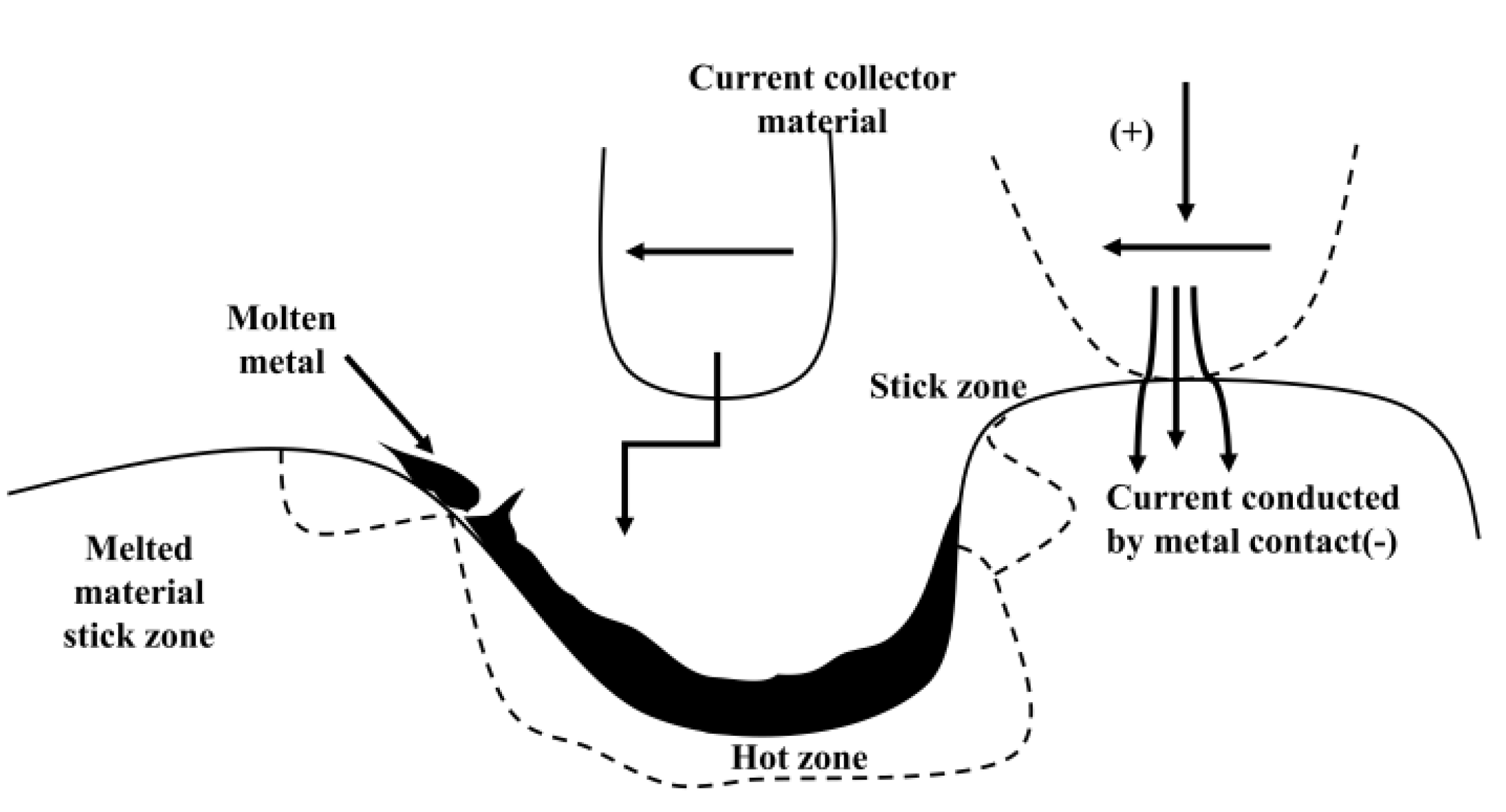
  • Arc erosion: The surface of the friction pair is not entirely smooth and has good contact, and a local loss of contact will occur in relative motion. The primary electron emission on the surface of the friction pair causes electrons to escape under the combined action of friction heat, Joule heat, and electric field. Due to ionization, the atoms or molecules in the out of contact gap will produce electrons and ions. In contrast, the electron or ion bombardment on the emission surface will cause secondary electron emission. Under a sufficiently large ion concentration in the gap, the gap will be electrically punctured, and an arc will occur. Arcs will produce many erosion pits and eventually result in arc erosion.
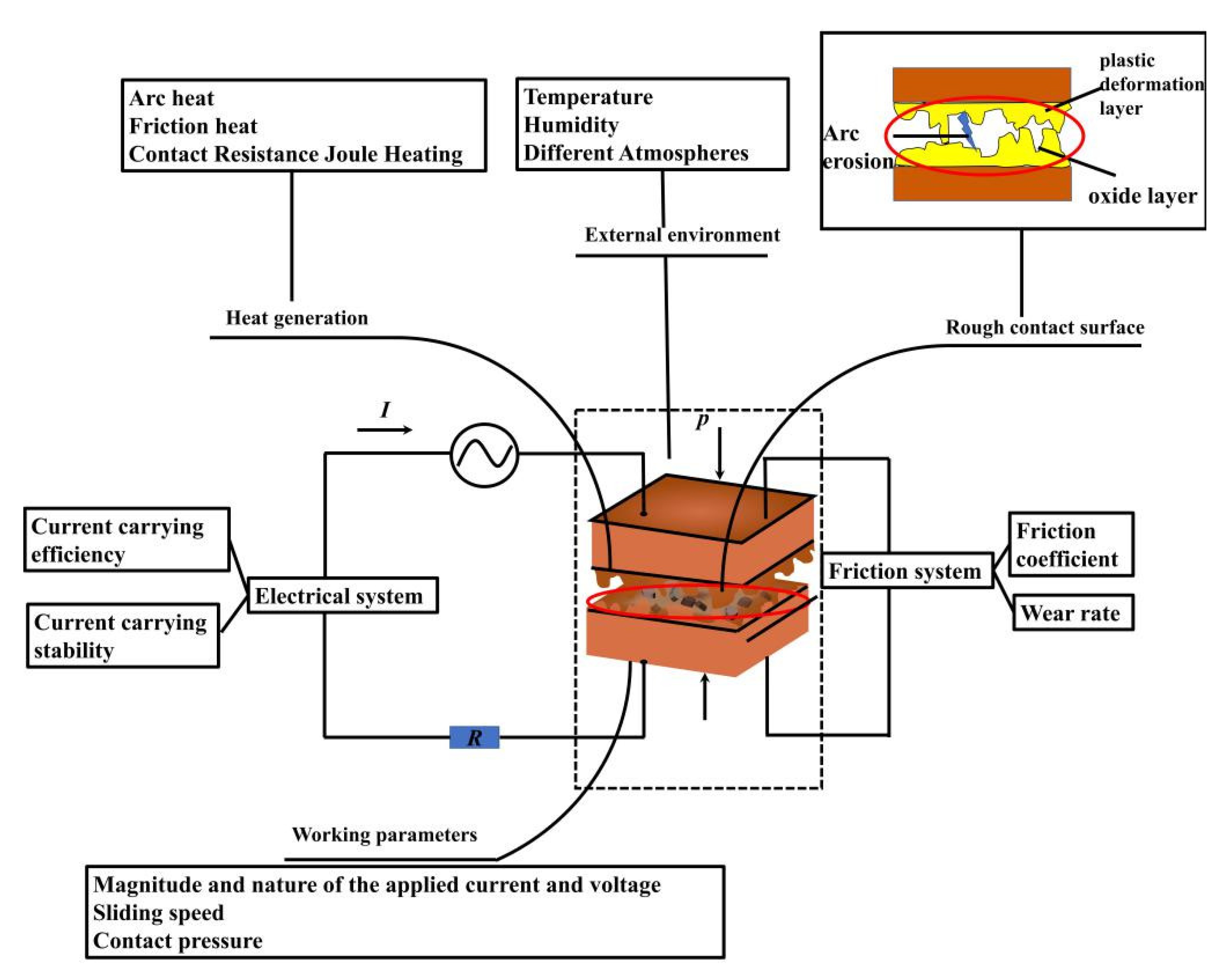
  • Mechanical arc synergy: The main feature of current-carrying friction damage is the coupling effect of mechanical wear and arc erosion. To be specific, when the contact pressure between friction pairs is enormous, the close contact contributes to the generation of arc erosion, whereas the friction will also increase correspondingly, increasing the mechanical damage of the material. As a result, the material surface integrity and uniformity will be reduced, and the arc erosion will worsen. In contrast, when the contact pressure between friction pairs is slight, although the friction and mechanical wear are small, the local loss of contact will cause an electric breakdown, resulting in arc erosion. As a result, the material surface is weakened, the roughness increases, and the mechanical wear is worsened. The coupling effect of the two primarily accounts for the material wear and current-carrying performance deterioration.

2.1. Contact Form of Friction Pair

Current-carrying friction and wear usually exhibit high speed and large current characteristics, resulting from the interaction between the mechanical friction contact system and the electrical contact system. Scholars have mostly employed self-made current-carrying friction and wear test devices according to the research objects and conditions, and there has been no unified test device. Common test devices can be classified into four categories, as shown in Figure 2.
In the contact separation process between friction pairs (Figure 3), the macroscopic smooth plane of the contact surface is an uneven rough plane in the microcosmic, and its actual contact area is only a few square millimeters. Colossal power is transmitted in this area. Moreover, the total contact area remains relatively constant, with the disappearance of the original contact points and the generation of new contact points in the friction process. The essence of friction results from the interaction between numerous concave-convex peaks. The concave-convex peak can be equivalent to a contact body in the calculation. In the current-carrying sliding contact between two contact materials, the current is conducted through the concave-convex contact between the contact bodies. The contact point of the contact body is termed as a conductive spot. When the current passes through the conductive spot, it will change the electric field distribution inside the two contact conductors, thus making the current flow from one contact conductor to the other. In the above process, the current will be distorted, and the contact current will converge at the conductive spot to produce a shrinkage effect. The resistance generated by current shrinkage is called shrinkage resistance. Furthermore, a film will be formed on the contact surface during the switching process to increase the resistance, which is termed as surface facial mask resistance [2,17].

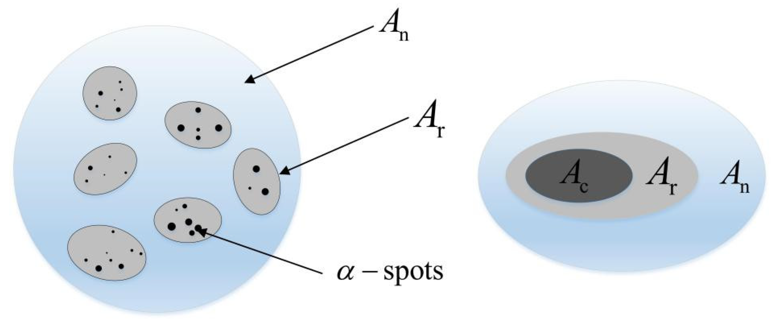
2.2. Contact Characteristics of Friction Pair in Relative Motion

In the process of current-carrying sliding, the force process between the concave-convex peaks on the surface of the two contact objects can be expressed as follows. During static contact, the concave-convex contact peak will undergo elastic deformation under the action of contact pressure. Moreover, a contact area with radius r will be formed between the two contact peaks. Furthermore, the conductive channel formed through this contact area will conduct current. When the contact body slides relatively, the surface of the contact body receives the normal pressure and the transverse friction. The micro convex part of the contact body will generate elastic deformation in the direction perpendicular to the moving direction, while it will be subjected to the shear strain of friction in the moving direction. Under the action of the above two forces, the contact surface will continue to change, resulting in the uneven distribution of the conductive current on the contact surface. Research suggests that with the increase in the sliding speed, the friction coefficient of the contact surface will decrease, and the shear stress on the contact surface will be reduced. Under the action of shear stress, the contact summit will undergo elastic deformation and plastic deformation. Due to the decrease in the shear stress, the contact peak will decrease, and the contact resistance will tend to increase. Moreover, in the process of current-carrying sliding, the contact surface will react with the unique atmosphere in the environment to form an oxide film, which has a poor stability. Due to the combined action of mechanical wear and the current thermal effect in current-carrying friction, considerable heat will be generated, and the oxide film will be partially damaged. The existence of mechanical stress will also accelerate the failure of the oxide film, so the contact resistance will drop again. With the increase in the contact body’s speed, the contact surface adhesion decreases. When it reduces to a particular value, the contact area of the contact body decreases. Furthermore, the oxide film and wear debris peeled off during friction will form an irregular surface, thus increasing the contact surface’s roughness. The superposition of multi-faceted factors tends to increase the contact resistance and further increase the temperature of the contact surface [18].

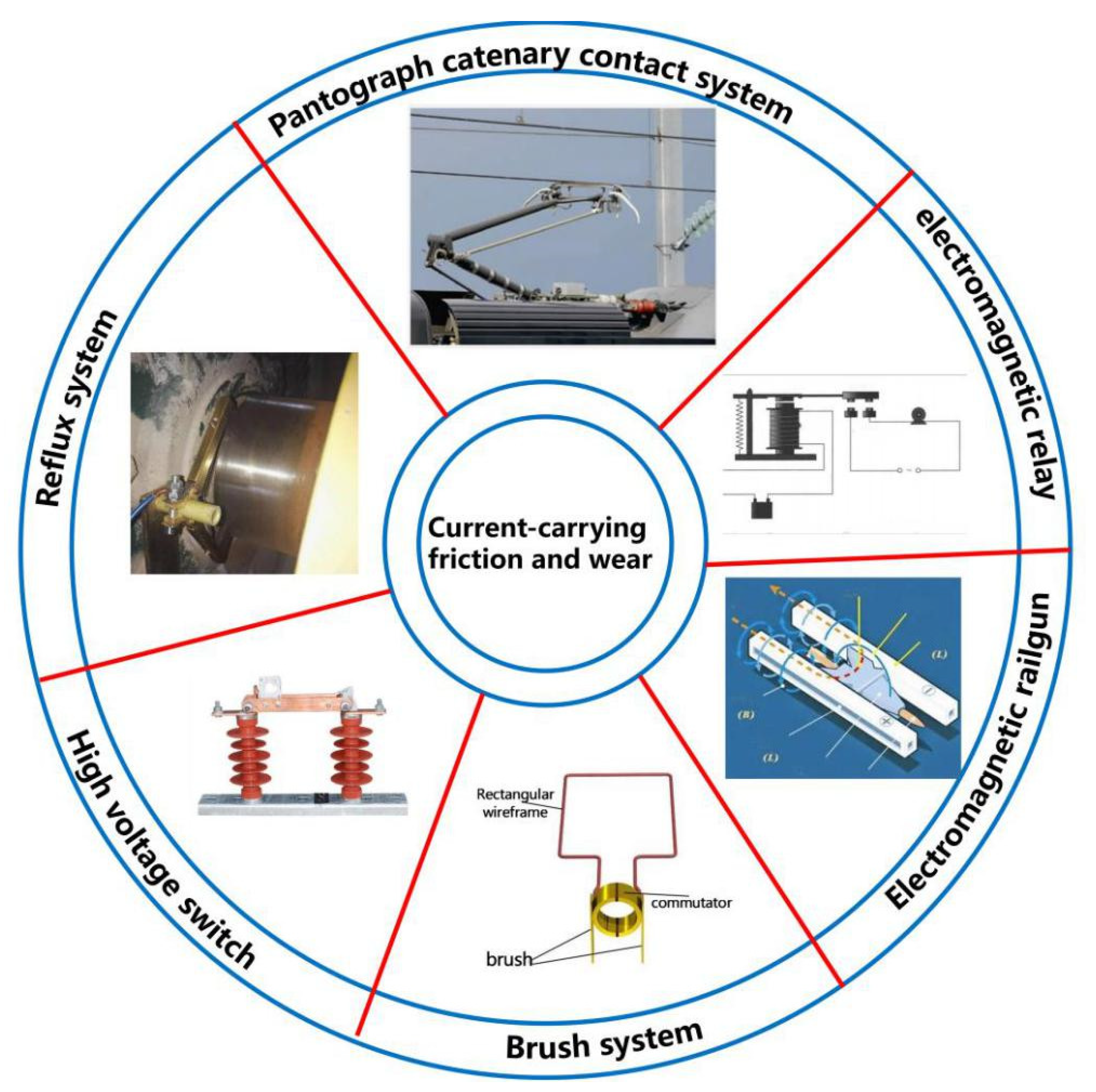
3. Research Field of Current-Carrying Friction and Wear

At present, in the current-carrying friction and wear research, some tests and comparisons of novel materials have been carried out for the brush, pantograph catenary system, and other systems involved in friction and wear to promote the practical application of novel materials in the field of friction and wear. Others have primarily studied the mechanism of the current-carrying wear, focusing on the effect of the following working parameters: sliding speed, load, current, electric field, magnetic field, arc, unique atmosphere, and electrode materials on the friction and wear characteristics [19], as shown in Figure 4.

3.1. Effect of Working Parameters on Current-Carrying Friction and Wear Properties

The research on current-carrying friction and wear performance and mechanism has largely focused on the effect of different working parameters on the current-carrying friction and wear. The study primarily uses the simulation test platform to simulate the operating conditions. The analytical means developed from the conventional analysis of the friction coefficient, wear rate, surface micromorphology, and abrasive debris to the current analysis of the increase in the contact surface temperature, contact resistance, arc study of the wear types, and contact materials. The current-carrying friction and wear mechanism can be divided into mechanical, electrical, and arc ablation and the surface oxidation process. The working parameters involved in the above three aspects include current, contact pressure, sliding speed, and arc. The effect of the operating parameters in the four aspects on the current-carrying friction and wear performance is summarized below.

3.1.1. Effect of Current Density on Current-Carrying Wear

The resistance heat and arc generated by the current-carrying friction pair transmitted to the current have an essential impact on the current-carrying friction and wear. The current size directly determines the effect of electrical factors on the performance of the friction pair. The current performance on the friction pair’s friction coefficient is more complex, and the major effect on the wear rate is that the wear rate increases with the increase in the current. Table 1 shows the structure and parameters by the relevant researchers and their testing machines.
Some scholars have used the wear rate to characterize the degree of current-carrying friction and wear. Using a block-to-ring wear tester, Kubota et al. [24] studied the wear behavior of copper-impregnated carbon fiber reinforced carbon composites (C/C composites). The wear test was performed at a constant sliding velocity of 55.6 m/s with a normal load of 59 N and an applied current ranging from 100 A to 500 A. The current-carrying wear experiments showed that the C/C composite contact strip with high-strength carbon fibers is more prone to wear under high arc discharge energy conditions (Figure 5). The C/C composites made from higher-strength carbon fibers had lower thermal conductivity and were more susceptible to pyrolytic or oxidative degradation than the C/C composites with lower-strength carbon fibers, which is what caused the difference in the wear behavior.
In addition to the wear rate, the change in the friction factor is also an important parameter to characterize the friction and wear process.
B. Shangguan et al.’s [25] research on a Qcr0.5 (disc)/brass (pin) matching pair found that with the current density increase, the matching pair’s friction coefficient tended to decrease. The friction coefficient decreased sharply when the current density was less than 1.1 A/mm2. After the friction coefficient was more significant than 1.1 A/mm2, the friction coefficient remained unchanged; with the increase in the current density, the wear rate of the brass pin sample showed an approximately linear increase trend [21]. Studies have shown that with the increase in the current density, the friction coefficient of the current-carrying friction pair tends to increase. Y. Zhao et al. [26] revealed through the current-carrying friction and wear test of the QCr0.5 (disc)/t2 (PIN) matching pair that the friction coefficient and wear rate increased with the increase in the current. The results also showed that the current influence on the friction coefficient of matching pairs under the current-carrying conditions was related to speed. Y. Zhang et al. [27] found that the current effect on the current-carrying friction and wear was different at different speeds. The friction coefficient decreased when it was higher than 40 m/s. Furthermore, with the increase in the current, the wear rate at each speed increased, and the wear rate increased sharply when the current exceeded 130 A.
Aside from the above conclusions, some scholars have proposed that the friction coefficient will decrease first and then increase. For instance, M. Guo et al. [28] performed tests and suggested that the friction coefficient and wear rate of a copper–silver alloy will decrease first and then increase.
K. Li et al. [29] studied the effect of the current density on the arcing rate, current-carrying efficiency, friction coefficient, and wear rate of the 3%SiS–10%C–87%Cu 10%C–90%Cu copper matrix composites. The research indicates that with the increase in the current density, the arcing rate of the two composites tends to increase, and the current-carrying efficiency tends to decrease. The friction coefficient of the SiC/C/Cu composites decreased first and then increased slightly, while that of the C/Cu composites decreased continuously, whereas the wear rate tended to increase. Some studies have even highlighted that the friction coefficient will increase with the increase and decrease in the current. L. Yang et al. [30] suggested that the friction coefficient of the mating pair first increases and then decreases with the increase in the current. When the load is 50 N, the peak value of the friction coefficient will be earlier than the other load values, and the wear rate of the C/C-Cu composites will increase with the increase in the current and the load. Some scholars have drawn similar conclusions. L. Ping et al. [31] suggested that the sample’s friction coefficient and wear rate first increased and then decreased with the current. Z. Chen et al. [32] also suggested that the current facilitated the formation of the surface facial mask of the friction pair, increased the film resistance, and finally decreased the wear rate and friction coefficient of the contact surface. A. Senouic et al. [33] investigated the wear mechanism of graphite/copper under electric sliding contact and suggested that the current affected the material transfer on the contact surface and the thickness of the oxide film.
Some scholars have reached the opposite conclusions through research. H. Zhao et al. [14] performed the tests and suggested that the friction coefficient and wear rate of the materials increased with the increase in the current. P. Li et al. [34] reached similar conclusions through research. Some scholars have also indicated that the effect of current on the wear rate and friction coefficient is not synchronous. For instance, Y. Wang et al. [35] suggested that the wear amount increased with the increase in the current, whereas the friction coefficient decreased.
In accordance with the different friction mechanisms of the material surface in the presence of current, F. Yi et al. [36] suggested that the current presence will increase the roughness and abrasive properties of the metal surface, thus increasing the wear volume and friction coefficient. When there is no current, the friction coefficient of the material decreases due to the existence of the lubricating film. H.H. Da et al. [37] and Y. Xu et al. [36] also drew similar conclusions through testing that the presence of the current will increase the wear rate.
In addition, some scholars have suggested that the current affects the friction and wear differently. For instance, S.G. Jia et al. [38] studied a copper alloy’s current-carrying friction and wear behavior and suggested that the material wear rate increased slowly at low, high, and rapidly at medium. Furthermore, the speed and average load significantly affected the wear rate at low current. Thermal wear and arc erosion became the dominant forms of wear under a high current. Wang, W et al. [39] also concluded that the wear mechanism, wear rate, and arc ablation degree varied with the current.
The addition of an electric current significantly affects the friction and wear performance of the friction pair, which will promote the wear and corrosion of the contact surface. With the current increase, the temperature between the friction increases, the adhesion wear, abrasive wear, and arc ablation intensify, the contact condition of the material surface becomes worse, and the friction and wear performance decreases. Zheng et al. [40] believed that the current density through a single contact point was several times higher than the average value in the case of power on, which generates Joule heat; on the other hand, the friction force caused friction heat to be generated at the friction interface at high speed. The joint action of resistance heat and friction heat causes the temperature to rise, and the formation of an oxide film on the surface causes the friction force to decrease. In the repeated sliding process, cracks are formed, and the oxide film breaks and falls off, resulting in increased friction, wear, and corrosion on the contact surface.
The effect of current on the surface of the friction pair is complex. The existence and size of the current will affect the electrical and tribological properties of the current-carrying friction and wear (including contact resistance, surface temperature increase, wear rate as well as friction coefficient).

3.1.2. Effect of Sliding Speed on Current-Carrying Wear

In the current-carrying friction and wear field, the running speed of electrified railways and electromagnetic rail guns is becoming faster and faster. High speed will lead to abnormal equipment vibration, electric spark, and arc discharge. The focus of research is the effect of speed on the current-carrying friction and wear. With the increase in the speed, the relative motion of the sliding current-carrying friction pair surface becomes more uneven. There will be problems such as jumping and impact, which will lead to more arc discharge between the friction pairs, shorten the contact time of the actual contact in the sliding contact process, and make the arc discharge or spark discharge process between the contact surfaces more unstable. Thus, with the increase in the speed, the friction coefficient changes in a complicated manner, and the wear rate increases with the increase in speed. Table 2 shows the structure and parameters of relevant researchers and their testing machines.
The running states of friction pairs were different at different speeds. Some studies have shown that the friction coefficient increases with the speed increase under current-carrying conditions. The research results of L. Wang et al. [46] on the matching of the C/C composite, metal impregnated carbon material (PIN), and QCr0.5 (disc) showed that the friction coefficient will increase with the increase in the speed. However, the increase was slight, and the wear rate also increased. Righdan namus et al. [27] also found similar conclusions through the experiments. They studied the effect of the reciprocating sliding speed on the wear and corrosion performance of the Ti6Al4V alloy under the open circuit potential of the cathode and anode in simulated body fluid. The research results showed that the sliding speed greatly influenced the micromorphology and wear rate of the worn surface (Figure 6). The wear rate at a low sliding speed was one order of magnitude lower than that at high sliding speed. The cooperative and antagonistic behaviors are closely related to the sliding speed.
Moreover, it is suggested that the friction coefficient decreases with the increase in speed. B. Shangguan et al. [47] investigated the matching of the SiCp-A1 matrix composite (PIN) and QCr0.5 (disc) and suggested that the friction coefficient tended to decrease with the increase in speed and that the wear rate began to change slightly, whereas it increased rapidly after the speed reached 10 m/s.
However, the research results on the matching copper-based powder metallurgy material (PIN) and QCr0.5 revealed that the friction coefficient first decreased, then increased to 50 m/s, and the wear rate increased with the increase in speed [24].
Some literature studies have also suggested that the friction coefficient and wear rate changed with speed as a single peak curve. S. Ji et al. [48] revealed that the friction coefficient and wear rate first increased, reached the peak, and then decreased with the increase in speed.
The sliding process will cause the vibration and impact of the friction pair, thus directly affecting the quantity, quality, and dynamic change process of the conductive contact spots in the process of sliding current-carrying friction, affecting the current receiving quality of the current-carrying friction pair. The primary performance is that the current-carrying quality of the friction degree will deteriorate with the increase in the sliding speed. X. Zhou et al. [44] explored the effect of sliding speed on the current-carrying friction and wear behavior of the AuNi9/AuAg35Cu5 friction pair and suggested that the increase in sliding speed will decrease the stability of the electrical contact performance of the friction pair, and facilitate the material transfer between the friction pairs. A significant microzone molten pool phenomenon was observed on the wear surface of the dual disk, thus further decreasing the stability of the current-carrying friction of the material. L. Wang et al. [46] revealed that there was a critical speed under the condition of argon, thus making the C/C couple show two states (including low friction and high friction).
A. Senouc et al. [33] revealed that at low speeds, the Joule heat generated by the current caused a temperature increase and oxidation on the contact surface, resulting in high friction coefficient and wear rate. At high speeds, the contact was interrupted due to the peeling off of the oxide layer, thus leading to the decrease in the friction coefficient and the increase in wear. A. Bouchoucha et al. [49] reached similar conclusions through research. S. Li [42] et al. revealed that the increase in speed led to a decrease in the contact area, an increase in the shrinkage resistance, an increase in the contact voltage drop, and an increase in the contact surface temperature as well as an increase in the wear rate.
L. Tian [50] suggested that the friction coefficient and wear increased significantly with increased speed. When the speed exceeded the critical value, the impact was intensified, thus increasing the arcing rate and decreasing the current-carrying efficiency.
M. Zhang et al. [51] suggested that as the sliding speed increased at 50–600 mm/s, the friction coefficient decreased, the fluctuation tended to increase, and the wear first increased slowly and then increased significantly. At low speeds, the wear mechanism mostly showed slight oxidation wear. At medium speeds, the wear mechanism changed to oxidation wear. Furthermore, at high speeds, the wear mechanism showed adhesion delamination wear.
However, some scholars have achieved the opposite results through experiments. Z. Yang et al. [52] suggested that the friction coefficient of materials increased with the increase in the sliding speed, and the wear first increased slightly and then increased rapidly. The wear surface was divided into the mechanical wear area and the arc erosion area. The mechanical wear area was largely dominated by furrow and rolling plastic deformation, and the arc erosion area was dominated primarily by melting. The arc erosion area increased with the increase in the speed, making the wear surface rougher.
W. Ma et al. [53] also determined a critical speed as the wear state will change when the required speed is exceeded (0.5 m/s). The reason for this finding is that the layered wear with a high strain rate will make it difficult to form a lubrication layer on the contact surface and increase the wear rate.
In addition to the parameters above-mentioned such as the wear rate and friction factor for current-carrying friction and wear, contact resistance has also been the focus of research. T. Chen et al. [54] used a rolling tribometer to study the effect of rotational speed on current-carrying tribological properties. As the rotational speed increased from 240 r/min to 600 r/min, the total friction force during the steady state increased from 3.8 N to 7.6 N. The contact resistance decreased from 0.52 Ω to 0.34 Ω (Figure 7 and Figure 8). Scanning electron microscopy and optical microscopy showed that high rotational speed and current promoted surface fatigue and cracks. The X-ray photoelectron spectroscopy results showed that more nascent metal is exposed on the rolling surface at a higher velocity, which is beneficial for electrical contact.
The speed change will result in a difference in the friction pair’s actual contact area and contact state. Moreover, the change in speed will cause a change in the interface temperature. In addition, due to the increase in the speed, the vibration of the friction pairs will be enhanced, and the friction pairs will have electric sparks and arc discharge. The above factors will affect the contact performance of the friction pair surface, thus resulting in the formation and destruction of the oxide film, the appearance of wear debris as well as the dynamic change in the contact resistance.

3.1.3. Effect of Load on Current-Carrying Wear

The load directly determines the contact state of the sliding current-carrying friction pair. From the tribological perspective, the smaller the contact force, the lower the wear rate will be. From the perspective of arc discharge, the smaller the load, the worse the electrical contact state will be; the higher the possibility of arc discharge, the more significant the increase of arc erosion will be. The complete results are presented as follows. Under the optimal load, the wear rate is the lowest, the contact state is the optimal, the arcing rate is the lowest, and the arc erosion effect is the smallest. The reliable contact and interaction between the two contact bodies ensure the excellent conduction of current-carrying friction and wear. The load affects the friction pair’s service life and stability as well as the maintenance cost. Accordingly, the research aimed to find the appropriate load size through experimental research and apply it in practical engineering. Table 3 lists the structure and parameters of the relevant researchers and their testing machines.
L. Dong et al. [56] explored the DC current-carrying friction of a steel aluminum composite rail. The results indicate that the friction and wear rate changed with load in the current-carrying current from large to small. Under pure mechanical friction and wear, the friction coefficient decreased, and the wear rate increased with the increase in the load. The friction coefficient changed slightly under the current-carrying friction test current of 20 A. At 50 A, the friction coefficient increased first. The friction coefficient remained unchanged when the load exceeded 50 N. In the case of current, the wear decreased first and then increased. The optimal load was 50 N; the greater the current, the greater the change range will be.
S. Zhang et al. [55] performed tests under the conditions of 250 A current, 160 km/h sliding speed, and 50, 70, 90, 110, 130 N contact pressure. The results indicate that with the decrease in the contact pressure, the surface morphology of the slider changed from smooth to pitted wear surface formed by arc splashing, and the worn form changed from abrasive wear to arc ablation wear. The friction factor tended to increase. The wear decreased and then increased, showing a “U” distribution. Increasing contact pressure can decrease the arc power and off-line rate, and 90 N is the optimal contact pressure when the wear rate is the minimum and the current-carrying stability is high. F. Guo et al. [57] drew a similar conclusion through research. When there was a current, the wear volume changed with the pressure in a “U” shape. The wear volume of the composite will be enormous under the extremely low pressure. The lubricating film on the contact surface was destroyed under the extremely high pressure, leading to the increase in the wear volume. F. Guo et al. [58,59] also suggested that the wear rate of the brush presented a “U” shape change, in which the wear rate increased with the increase in the load in the case of pure mechanical wear, and the pure electrical wear rate decreased with the increase in the load. This law has also been reflected in the research of other scholars. Some scholars obtained a pressure threshold (70 N) to keep the wear rate of the sliding plate at the lowest level. The pressure threshold increased with the increase in the current. X. Xu et al. [60] also suggested a conclusion similar to the above research, where with the increase in the pressure, the friction coefficient increased, and the wear rate decreased under a low load. With the further increase in the load, the wear rate also increased, thus showing a “U-shaped” curve change.
However, some scholars have drawn different conclusions through research. Yasar et al. [61] suggested that the wear rate changed in a “U” shape with the increase in the contact pressure, whereas the friction coefficient and the contact pressure dropped first decreased and then increased with the contact pressure. Other scholars have indicated that the contact pressure does not significantly affect the friction coefficient. Some scholars have found that under different current conditions, with the increase in the contact pressure, the friction coefficient showed different changes, which may show an upward trend or a similar “U” curve change. T. Ding et al. [62] studied the effect of pin support stiffness on the friction and wear behavior of stainless steel/copper-impregnated metalized carbon under the action of an electric current on a pin-on-disk testing machine. The research results showed that at low speed or a small current, the friction coefficient increased with the increase in stiffness (Figure 9a). In contrast, at high speed or high current, the friction coefficient first decreased and then increased with the increase in stiffness (Figure 9b). The wear rate of the pin samples with elastic support was much lower than those with rigid support. The lowest wear rate was found when the stiffness was equal to 19,000 N/m (Figure 10). The study found that abrasive wear and adhesive wear mainly occurred at low speed or low current, while oxidative wear and arc ablation mainly occurred at high speed or high current. Comparing the cross-section scar, profile, and surface roughness of the pin samples with different stiffnesses, it was found that the pin wore the most when it was rigidly supported and the least wear was when it was supported by a spring with an appropriate stiffness (19,000 N/m).
L. Dong et al. [63] obtained a critical normal pressure in the test process. When it was higher than or equal to the critical value, the friction coefficient and the wear rate increased with the increase in the current; when it was lower than the critical value, the friction coefficient decreased with the increase in the current, and the wear amount increased with the increase in the current. The reason for the above finding is that the normal load increases the contact between friction pairs, and the wear rate is low due to abrasive wear and adhesive wear. Under the small average load, the discharge between friction pairs is severe, and the wear amount increases due to arc ablation and high-temperature oxidation wear [64]. Some of the research results are not consistent with the previous conclusions. Y. Zhang et al. [27] revealed that when the load ranged from 0.3 to 0.55 MPa, the friction coefficient decreased, and the wear rate increased, and there was no optimal load. The study also drew the opposite conclusion that with the increase in the load, the wear rate of the material increased with or without the current. However, the existence of a current can significantly decrease the friction coefficient. When there exists a current, the wear rate tends to increase; however, without a current, the wear rate tends to decrease, and the existence of a current will reduce the wear rate. T. Ding et al. [65] and R. Liu et al. [66] reached similar conclusions through the experiments.
The effect of load on arc discharge during the sliding current-carrying process is largely based on the effect of load fluctuation on the contact conditions. L. Tian and others [67] studied the effect of fluctuating load on the friction and wear. The results indicate that the friction coefficient and wear rate first decreased and increased with the increase in the load. When the load fluctuated, the wear mechanism was abrasive wear. The wear mechanism changed to abrasive and electrical wear when the load fluctuated significantly.
The load’s size will affect the friction pair’s electric contact state, and the number of conductive spots is significantly correlated with it. Since the impact and vibration formed during the operation of the friction pair produce fluctuations in the load, the electric contact in the current-carrying friction process is in a dynamic equilibrium state, and the fluctuation of the load will change this dynamic equilibrium state. Thus, the conductive contact state will change with the change in the load, and the current-carrying mass will also change.
Most studies have revealed that the current-carrying efficiency decreases with the increase in the load, and the current-carrying stability worsens. B. Shangguan et al. [68] conducted the research and suggested that the current-carrying efficiency increased with the increase in the load for metal impregnated carbon materials. At the speed of less than 30 m/s, the load had a limited effect on the current-carrying efficiency. At the speed of 40 m/s, the current-carrying efficiency was less than 90% under a load less than 100 N. When the load was more significant than 100 N, the current-carrying efficiency was close to 90%. With the increase in the load, the current-carrying efficiency region was stable. At the speed of 50 m/s, the current-carrying efficiency was low. With the increase in the load, the current-carrying efficiency will also increase, but is still less than 85%. For the C/C composites, when the speed was lower than 20 m/s, the current-carrying efficiency was higher than 90%. At the speeds of 30 m/s and 40 m/s, the load was more significant at 60 N and 80 N, respectively, and the current-carrying efficiency was stable at over 90%. The current-carrying efficiency is small at a speed less than this value. At the speed of 50 m/s, the current-carrying efficiency increased with the increase in the load, whereas it was less than 75%. It was also found that the current-carrying efficiency and stability were better when the load exceeded a specific value for different speeds under a given current.
However, some scholars have revealed that there are extreme points of current-carrying stability. J. Zhang et al. [69] suggested that the current-carrying stability will deteriorate with the increase in the load. Through fitting, it was confirmed that the current-carrying stability was the worst when the load was nearly 0.23 MPa. Some scholars have also analyzed the relationship between the fluctuation and current-carrying efficiency. L. Tian et al. [70] studied the C/C composites and chrome bronze fittings. They showed that with the increase in the load fluctuation, the off-line rate gradually increased, the arc energy gradually increased, and the current-carrying efficiency gradually decreased.
The mechanical wear increased with the increase in the load, while the electrical wear decreased with the rise in the external load. Increasing the normal pressure intensified the mechanical wear to a certain extent. However, due to the close contact between the friction pairs, the contact area increased, inhibiting the arc discharge to a certain extent, thus alleviating the wear between the friction pairs. Accordingly, an appropriate load can interfere with the arc ablation and avoid severe mechanical wear, a maximum amount of minor wear [64].
Previous studies have shown that the speed, current, and load affects the current-carrying friction characteristics. Further studies have shown that for the current-carrying friction performance of matching pairs, the severity of working factors on the current-carrying wear performance can be classified into current, speed, and load from large to small. For the current-carrying quality of the current-carrying friction pair, the severity of the working factors on the current-carrying wear performance can be classified into speed, load, and current. In [69,70,71,72], three kinds of materials (i.e., powder metallurgy sliding plate material, metal impregnated material, and C/C composite material) were used to conduct orthogonal tests on the effect of the working parameters on the current-carrying friction performance of chromium bronze (QCr0.5) matching pairs. The research results showed that the research results of the three pairs are in line with this law.

3.1.4. Effect of Arc Ablation and Temperature Increase of Contact Surface on Current-Carrying Wear

The arc generation is related to the type of insulating medium, pressure, electrode material, geometry, the distance between two electrodes, the voltage applied at both ends of the friction pair, and other factors [58,73].
The electric arc is caused by the electric potential difference of the contact surface exceeding the critical value. The arc exhibits two physical characteristics including steam arc and gas arc. The steam arc occurs in metal vapor, largely playing a role in metal ions, metal atoms, electrons emitted by the cathode as well as electrons excited by the inelastic collision between electrons and metal vapor. In the gas arc, the dominant particles are gas ions, gas molecules or atoms, and metal atoms [74]. The arc erosion will seriously damage the surface of the friction pair, which will consume the friction pair materials and aggravate the current receiving wear of the friction pair. The heat generated by arc discharge and Joule heat generated during the current conduction will increase the contact surface temperature [75,76]. Many scholars have studied the effect of temperature on the contact surface in the process of current-carrying wear. Z. Yang et al. [72] suggested that the temperature at the contact increases with time; the higher the current, the higher the temperature will be. The temperature increases rapidly first and then tends to be stable. On one hand, the increase in temperature will soften the contact surface, and the micro convex body on the contact surface is more prone to wear, thus resulting in the reduction in the roughness and friction of the contact surface. On the other hand, in the process of sliding electrical contact, a layer of thick oxide film will be formed on the contact surface to play the roles of friction lubrication and reduce friction. Furthermore, the increase in the temperature will lead to material wear between the contact surfaces [77].
D. H. He [16], C.R.F. Azovedo [78] and K. Kato [79] suggested that the off-line arc causes oxidized hard spots on the surface of the friction pair. The hard spots peel off during the wear process, and the arc splash will form tiny particles. The hard spots and small particles become the third phase (abrasive particles), resulting in abrasive wear. As the arc leads to a high temperature, the temperature of the friction pair surface will increase further, thus softening the friction pair surface material and generating adhesive wear.
S. Kubo, and K. Kato [15,79] focused on the effect of the current and arc on friction and wear. The effect of arc on wear is primarily indicated in the impact on temperature. Arc leads to metal melting, gasification, and severe oxidation. The wear rate depends on the density and duration of the arc discharge. To reduce the effect of the arc on material wear, the generation of friction surface heat should be reduced, and the surface pressure should be increased by making the contact surface contact well to reduce the generation of the arc.
J. Bu et al. [80] investigated the effect of temperature on the current-carrying friction and wear behavior and suggested that the wear mechanism is largely abrasive wear in the low-temperature range (100–160 °C) and adhesive wear in the high-temperature range (above 200 °C). The resulting high temperature will lead to the formation of an oxide and molten layer on the contact surface of the carbon sliding plate. B. Shangguan et al. [81] studied the effect of temperature on the material. They suggested that with the increase in temperature, the material surface softens and forms a metal lubricating film, reducing the surface wear. Moreover, with the increase in temperature, the metal material will melt into the surface of the contact wire and eventually lead to the disappearance of the lubricating film on the metal surface. The high temperature will lead to the sublimation of the carbon fiber and aged carbon of the C/C composite material, which will be deposited on the surface of the carbon sliding plate to lubricate, reduce wear, and reduce the arc discharge.
Mei et al. [82] also pointed out a linear relationship between the arc ablation formed by arc discharge and the temperature increase in the contact surface through test data fitting.
Aside from the effect of arc on temperature, other scholars have conducted relevant research on the effect of the current-carrying stability and efficiency in the arc process on current-carrying wear. Kubos et al. [83] studied the change process of arc energy during sliding current-carrying friction. The results showed three stages of electric contact formation, stable transmission, and failure from the arc perspective.
L. Tian [70] investigated the effect of the arcing rate on the current-carrying efficiency under different working conditions. The result revealed that the increase in the arcing rate led to the increase in the energy dissipated in the arc and the decrease in the current-carrying efficiency. S. Ji et al. [84] explored the effect of arc energy on the current-carrying efficiency. It was also suggested that the generated arc will radiate and dissipate energy and eventually lead to a decrease in the current-carrying efficiency.
To conduct research close to engineering practice and further explore the effect of arcing rate on the current-carrying stability, J. Liu et al. [85] obtained the correlation between the off-line rate and current-carrying quality, arc energy, and friction coefficient by adjusting the speed under the current of 1.33 A/mm2 and the load of 0.41 MPa. The current-carrying quality worsens with the increase in the current-carrying off-line rate. The reason for this finding is that when the off-line rate is too large, the arc cannot be maintained, thus resulting in power supply interruption, a loss of traction of the electric locomotive, and the deterioration of the contact surface quality as well as the deterioration of the current-carrying quality.
The appearance of the arc will affect the current-carrying friction and wear process. Aside from the deterioration of the contact surface due to ablation and the increase in wear, the arc will also increase the contact surface temperature. The role of arc and other processes is not a simple superposition, but the result of interactions with interactions.

3.1.5. Influence of Multi-Factor Coupling on Wear

Many scholars have also studied the action mechanism of multi-factor coupling in the current-carrying friction and wear process.
A. Senouci et al. [33] suggested that the current, arc, and electric heating will promote the oxidation wear of materials, and the polarity will also affect the wear of materials.
Through experimental research, Bucca et al. [86] suggested that the interaction between contact load and current more significantly affected the wear, and the effect of contact load on the wear rate was dependent on the current. High load wear was severe under low current conditions, whereas it was the opposite under high current conditions. The effect of current on the wear rate also depended on the load. At a high load, the wear rate decreased with the increase in the current, but it was the opposite at low load. There was no “current lubrication” effect under the extremely large load. The wear was primarily mechanical wear. The effect of current on the current-carrying friction and wear will increase with the decrease in the load. As the contact resistance increased with the decrease in the contact load, the flash temperature in the contact area was high, thus increasing the melting wear and the wear rate. The wear of friction pairs is intensified under the coupling action of current and speed. When the load was constant, the temperature of the contact surface increased with the increase in the current, which caused the local melting of materials, thus resulting in increased surface roughness. When the sliding speed increased to a specific range, the surface roughness of the friction pairs increased, thus increasing the impact vibration between friction pairs, increasing the friction coefficient, wear rate, and arc erosion, and worsening the wear of contact surfaces.
Aside from the research on the effect of load current and current speed coupling on the current-carrying wear, some scholars have proposed the concept of the PV factor, the effect of the coupling between load and speed on the current-carrying wear. X. Zhang et al. [87] found that lower normal pressure and sliding speed caused plowing wear, while higher normal force and higher sliding speed caused oxidation stratification. The lower normal pressure and higher sliding speed promoted the formation of the transfer film. A sliding velocity of 1.0 m/s and a normal force of 0.25 N showed a stable low coefficient of the friction and wear rate (Figure 11). The prediction maps predicted the wear mechanism, friction coefficient, and wear rate of the Ag/MoS2/WS2 nanocomposites for different sliding speeds and normal pressures.
Y. Wang et al. [88] studied the effect of PV factor on the tribological behavior of copper-impregnated metalized carbon brushes sliding on Cu–Cr–Zr rings, tested at two currents (0 and 20 A) and contact pressures (p) and sliding speeds (v) under seven different combinations. The results showed that mechanical wear exacerbated the electrical wear (Figure 12), and a higher interface temperature was responsible for the higher wear rate. The degree of tribal-oxidation at the brush increased with increasing PV, which had a significant effect on the tribological behavior of the brush specimen.

3.2. Impact of Environmental Conditions and Surface Facial Mask on Wear

In the process of current-carrying friction and wear, aside from the current density, contact load, sliding speed, and arc ablation, environmental conditions and the surface facial mask that form due to physical or chemical effects in the friction process also have an important impact on the tribological properties of electric contact.
There are a wide variety of climate and environmental conditions in the service area of the current-carrying friction pair, so the effect of humidity on the current-carrying friction and wear should be studied. Z. Hu et al. [89] reviewed the effect of humidity on the wear rate of materials and suggested that water molecules with high moisture will lead to the formation of a short film on the contact surface and an oxide layer with a lubricating effect through a chemical reaction to reduce adhesive wear. Furthermore, the low humidity water film did not cover the entire contact surface, resulting in the increase in wear. Z. Hu et al. [90] performed tests in underwater mist and dry friction environments, respectively. The results indicated that the friction coefficient changed slightly in the two environments, and the friction coefficient was low in the underwater mist environment. At low speeds, the existence of water mist decreased the wear rate, thus leading to the reduction in the wear rate at high speed. The friction coefficient and current-carrying stability had a slight effect under the condition of water mist. At low speeds, water mist can increase the current-carrying efficiency and decrease the current-carrying stability. However, water mist decreases the current-carrying efficiency and stability at high speeds, thus resulting in the deterioration in the current-carrying quality.
The pantograph catenary system, as a current-carrying friction and wear system exposed outdoors for a long time, is vulnerable to environmental conditions and environmental atmospheric changes. Matsuyama Jinzuo et al. [91] performed experiments and suggested that with the participation of water, the Joule heat and arc generated when the pantograph and catenary are energized rapidly expand and vaporize the water, generating heat dissipation, and reducing friction, thus leading to the significant increase in arcing. The mutual bonding effect of the arc on the convex part will increase the loss, and the surface cooling effect will offset the arc heat effect.
C. Song et al. [92] studied the tribological and conductive properties of the current-carrying rolling pairs in moist air and water droplets. The current-carrying friction coefficient changed from 0.14 to 1.03 as the environment changed from a very low relative humidity atmosphere (10% relative humidity) to liquid water, and increased to 1.03. As the friction coefficient increased (Figure 13), the wear mechanism of the current-carrying pair changed from adhesive wear and abrasive wear to severe fatigue wear. When the water changed from a gaseous state to a liquid state, the form of fatigue changed from scaling to spalling due to the pressurization effect. Water favors tribal oxidation and electrochemical oxidation, leading to the formation of CuO.
H. Zhang et al. [93] performed friction and wear tests in the air and nitrogen environment and suggested that the friction coefficient is higher in a nitrogen environment. The reason is that the friction pair comes into direct contact in the friction process under the inert protection of nitrogen, and the contact surface is rougher. The friction surface will be more easily oxidized in the air to form an oxide film, thus decreasing the friction coefficient. The nitrogen condition leads to the weak contact surface activity and the higher empty bond energy. Furthermore, the friction coefficient is high.
Besides studying the effect of environmental conditions on pantograph catenary current-carrying friction pairs, some scholars have also studied the effect of environmental conditions on other forms of current-carrying friction pairs.
Y. Sun et al. [94] indicated that the friction coefficient increases when the relative humidity is high. The wear mechanism changes from slight adhesive wear and abrasive wear to severe layered fatigue wear with the increase in the relative humidity. Water vapor with different humidity participates in friction oxidation and electro-chemical oxidation. Surface oxides increase the contact resistance while reducing the conductivity of the friction contact pairs.
The following year, Y. Sun et al. [95] explored the effect of water on the rolling friction pair. The research indicated that the friction coefficient increased with the increase in the current. A high friction coefficient led to surface pits and plastic flow. There are two mechanisms for the formation of copper oxide in the current-carrying process (including oxidation reaction and electro-oxidation reaction). The oxide generated on the contact surface will decrease the conductivity.
Y. Sun et al. [96] compared the friction coefficient and contact resistance in a dry and wet environment at different rotating speeds through experimental research. The study results suggested that when the rotating speed increased from 30 r/min to 480 r/min, the underwater friction coefficient decreased from 1.06 to 0.49, and the underwater friction coefficient was significantly higher than the dry friction coefficient. The underwater contact resistance increased from 0.57 Ω to 6.4 Ω. The underwater contact resistance was higher than that at a dry state. The capillary effect was generated at a low rotating speed. The friction coefficient was high, and the wear mechanism was flaking. At high speeds, the friction coefficient was low, and “water pressure” caused fatigue spalling on the material surface.
G. Chen et al. [97] studied the effect of environmental humidity on the carbon/copper current-carrying sliding contact pair. The friction coefficient under the current-carrying condition was higher than that under the no current state. The arc discharge energy and average contact resistance were positively correlated with the relative humidity. Under the current-carrying condition, there was an optimal humidity value with the lowest degree of adhesive wear, which appeared near 55% RH. The change in the molecular structure of the contact surface is facilitated under high humidity.
Existing research suggests that the ambient temperature will change the mechanical properties of the material, thus changing the electrical and mechanical contact properties and affecting the overall performance of the current-carrying friction pair. J. Bu et al. [81] studied the effect of temperature at the speed of 66 km/h, 55 N, 50 A, or 0 A. The research results revealed that the friction coefficient increased with the increase in the temperature at a lower temperature (100–160 °C). At a temperature higher than 160 °C, the friction coefficient decreased. Once the current was equivalent to 50 A, the friction coefficient decreased with the increase in the temperature. The wear loss increased with the increase in the temperature. The effect was small at the low temperature. At a temperature below 160 °C, there was a slight difference between the wear amount of the charged materials and that without current.
Different environmental atmospheres will affect the current-carrying friction and wear. B. Shangguan [68] investigated the current-carrying performance of pure copper and chromium bronze under oxygen and atmospheric conditions. As revealed by the results, the friction coefficient and wear rate under oxygen conditions were lower than those under atmospheric conditions. The friction coefficient of matching pairs under an oxygen atmosphere was lower than under air conditions. Thus, an oxygen atmosphere helps to improve the friction and wear performance. B. Jia et al. [98] conducted current-carrying friction and wear research in different atmospheres. The friction coefficient in the air environment was lower than in the nitrogen environment, whereas both trends were the same. With the increase in the current, the friction coefficient decreased and then increased. The friction coefficient in the two environments was close under the current of 100 A.
The existence of surface facial masks (e.g., oxide films) also has effects on the current-carrying friction and wear process. S. Sawada et al. [99] analyzed the current density distribution law in the semiconductor contact area and suggested that the current was primarily distributed in the oxide film area and evenly distributed under the existence of an oxide film. However, some scholars have indicated that the existence of an oxide film will not affect the current-carrying process. For instance, Grandin et al. [100] performed the tests and suggested that the contact resistance was the lowest when the oxide content in the oxide film was high, and that the existence of oxide will not affect the electrical performance of the current-carrying friction and wear.
The operating conditions of friction pairs with current-carrying friction and wear are becoming increasingly severe. Aside from high speeds, high currents and high loads, severe vibration, effect, resistance to different humidity, ultra-high vacuum, high and low-temperature alternation, atomic oxygen, and intense radiation will also occur during operation [101]. Accordingly, research into the materials’ friction and wear properties and failure mechanisms under the coupling action of vacuum, contact load, current, speed, temperature, and humidity takes on a critical significance.

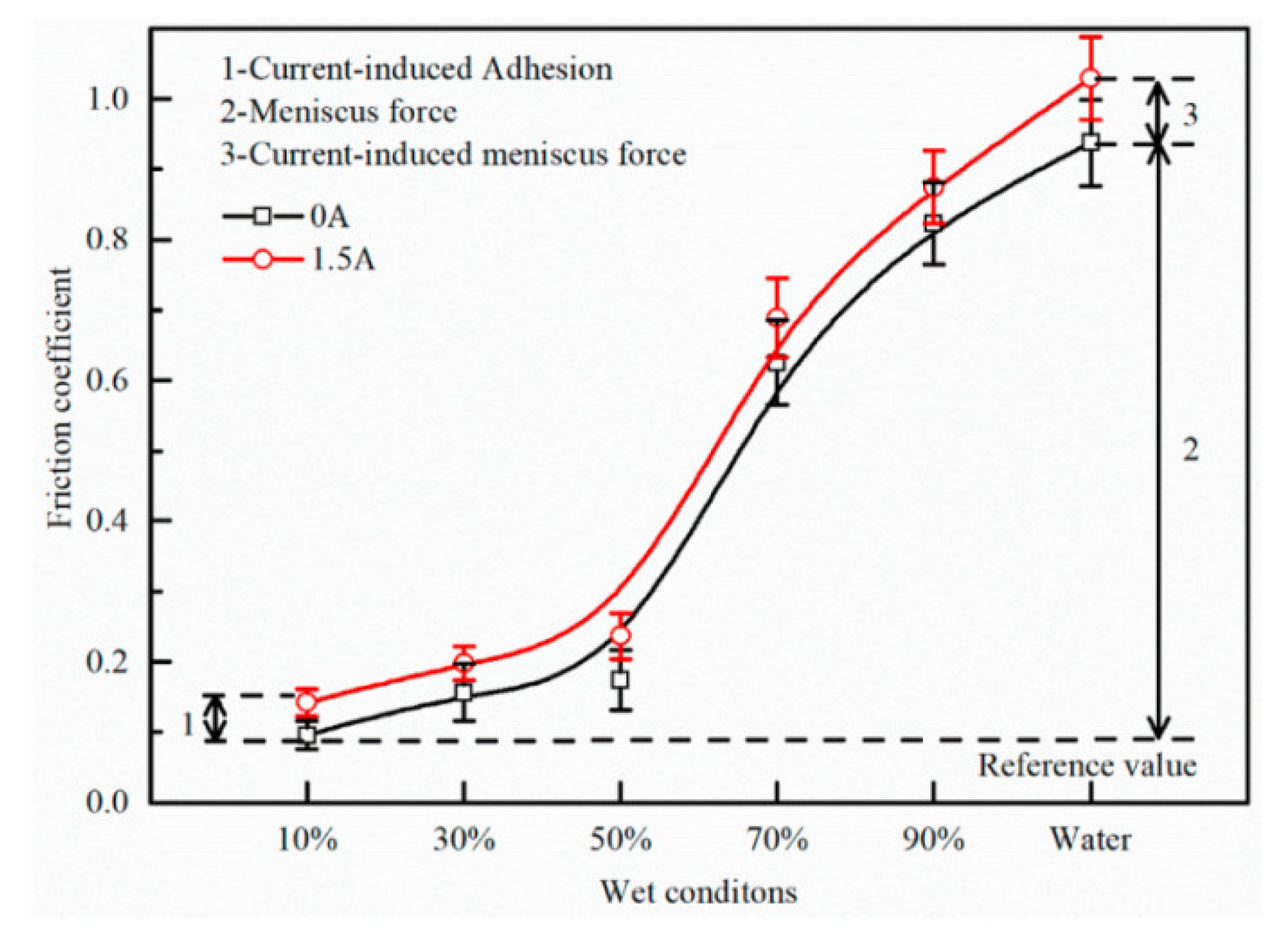
3.3. Effects of Current-Carrying and Friction Coupling on Friction and Wear Performance

The friction contact system and the electric contact system interact and couple in the operation process. The current-carrying friction pair is in a complex environment of an electromagnetic field, temperature field, and stress coupling field, and its performance will also show coupling characteristics. The heat generated in the dry friction process directly damages the contact surface, destroys the current-carrying friction and wear state, and affects the electrical conductivity of the friction pair [102,103,104]. The arc, resistance, and oxidation in the process of conducting electricity affects the characteristics of the friction pair, which determines that the pressure, speed, and other factors not only directly affect the tribological performance of the current-carrying friction pair, but also affect the conductive characteristics of the current-carrying friction pair. Voltage, resistance, and other factors not only directly affect the electrical conductivity, but also affect the tribological properties. Under the double coupling action, the current-carrying friction pair presents complex conduction friction characteristics. Therefore, the performance of the current-carrying friction system shows strict non-monotonic features, and the influence on the current-carrying friction and wear is the result of the coupling effect of various factors.

4. Preparation Method of Conductive Wear-Resistant Self-Lubricating Coating

4.1. Cold Spraying Technology

Cold spraying is a thermal spraying technology based on the principle of gas dynamics. During the spraying process, particles collide with the substrate at a very high speed (300–1200 m/s) and deposit on the surface to form a coating through solid plastic deformation. Presently, conductive and wear-resistant coatings prepared by cold spraying are widely used in electrical engineering [105,106].
At present, the hot spot of research involved copper-based coatings. Because the hardness of the pure copper coating is low and the wear resistance is poor, researchers have usually added hard particles to the copper-based coating. The addition of reinforcing particles improves the hardness of the composite coating. However, the bonding between such particles and the coating is poor and may fall off during the wear process, resulting in three body wear and reducing the wear resistance of the coating. At the same time, during the cold spraying process, the copper particles will produce large plastic deformation under the high-speed impact, lattice distortion will occur, and the scattering effect of electrons will be enhanced. In addition, the introduction of low conductive phase particles makes the contact resistance of the composite coating relatively high [107].
Many scholars have focused on enhancing the adhesion and wear resistance of the coating. Tazegul et al. [108] added Al2Cu particles to the copper-based coating. The Al2Cu and Cu particles have strong binding effects and good chemical compatibility. The coating containing 10% Al2Cu had high hardness, reducing the friction coefficient by 33% and the wear rate by 80%. The conductivity of the coating can be improved by adding high conductivity reinforcing materials and reducing the porosity of the coating. The ultra-high conductivity copper matrix composite has attracted extensive attention from scholars due to its excellent conductivity [109]. In this regard, researchers at home and abroad can refer to this composite material’s composition system and reinforcement mechanism to prepare an ultra-high conductive copper-based composite coating without affecting the friction performance.
Recently, the reinforced phase with high wear resistance and low friction property has also attracted attention. Z. Yang et al. [110] studied the dry tribological properties of the copper-based self-lubricating and wear-resistant composite coating and the matrix by preparing the copper-based self-lubricating and wear-resistant composite coating with Ni as the intermediate connecting layer on the surface of #45 steel. It was found that the friction coefficient and wear rate of 4 wt% carbon fiber and 2 wt% graphite samples were lower than those of #45 steel and showed the best tribological performance under 15 N load and 500 R/min rotation speed. The reason is that strengthening metal Ni and carbon fiber improves the microhardness of the composite coating, while the addition of graphite reduces the microhardness of the copper-based composite coating.
Post-heat treatment also has a significant effect on the properties of the coating itself. Tazegul et al. [111] prepared a SiC reinforced copper matrix composite coating on the surface of pure copper. It was found that with the increase in the SiC content, the wear performance of the coating surface was improved. After heat treatment at 600 °C, the sintering effect improved the cohesion between particles and further reduced the wear rate of the coating. After annealing at 500 °C, the surface resistivity of the pure copper coating was 3.33 × 10⁻⁶ Ω/cm, and the electrical performance of the coating was improved [112]. Therefore, the mechanical and electrical properties of the coating can be improved by improving the internal defects of the coating through appropriate heat treatment.
The coatings prepared by cold spraying technology have good electrical conductivity and have been widely used in surface strengthening fields such as electrical contact. With the rapid development of cold spraying technology, its low-temperature and high-speed characteristics will be further developed and utilized. Researchers should focus on the effective combination between particles, coating deposition mechanism, and post-heat treatment, and improve the corresponding theoretical research on coating.

4.2. Supersonic Plasma Spraying Technology

Supersonic plasma spraying technology is a method that uses the “extended arc” generated when the non-transfer plasma arc and the high-speed gas flow are mixed to obtain a stable and concentrated plasma flame for spraying.
In recent years, the conductive wear-resistant functional coating prepared by this technology can effectively alleviate the failure forms such as gouging, ablation, and high-temperature wear of the coating surface in the process of current-carrying friction, especially in a harsh current-carrying friction environment such as high current-carrying and heavy load, and can effectively protect essential parts and components. For example, the surface of the electromagnetic rail gun is strengthened. In the early stage, the rail materials are mainly blocking materials. In order to alleviate the skin effect of the current and friction surface effect in the process of current-carrying friction, coating technology has been adopted to improve its surface performance. Among them, Cu and its alloys have become the first choice of base materials due to their excellent conductivity. In selecting coating materials, tin, TaN, Al, Ni, and other materials have become the primary coating materials studied. At the same time, researchers have also studied coating lubricants on the surface of the friction pair to enhance its current-carrying friction performance [113].
J. Cui et al. [114] prepared a ZrO2 coating on the surface of a Q235 steel substrate by supersonic plasma spraying technology. There were many particle bumps and holes on the coating surface, with a porosity of 13%. Under the action of high temperature, the Zr element in the coating diffused from top to bottom, and the coating material changed phase during the spraying process. The microhardness of the surface of the coating and the substrate was improved compared with that of the substrate. J. Cui et al. [115] also prepared a zirconia ceramic coating by supersonic plasma spraying technology and carried out cyclic thermal shock tests with different cooling media. The research results show that the thermal shock resistance of a zirconia single layer coating under air cooling conditions is better than that under water cooling conditions, but the overall thermal shock resistance is low and needs further improvement.
G. Liu et al. [8] prepared Mo coating by supersonic plasma spraying technology. The results showed that the electrical conductivity of the coating was 6.01% IACS. The addition of W improved the microhardness of the coating, effectively suppressed the generation of gouging and scratches, and enhanced the wear resistance and wear resistance [9]. After the current friction wear appeared, adhesion wear, abrasive wear, and arc ablation wear occurred on the surface of the Mo–W coating [10]. Adding Cu improved the electrical conductivity by about 40% compared with the pure Mo coating. The Mo coating had the lowest friction coefficient and the smallest wear volume [11].
Post-heat treatment in supersonic plasma will also affect the coating. Y. Zhang et al. [116] controlled the carbide morphology and distribution by post-heat treatment and pulsed laser remelting to homogenize the coating structure. It was found that the uniformly distributed re-solidified chromium carbide phase effectively improved the corrosion resistance of the coating.
At present, there are still many shortcomings in supersonic ion spraying technology. There is noise, dust, and arc light radiation in the early supersonic spraying process. The working environment is poor, the spraying cost is high, the powder utilization rate is low, and it is not easy to carry out large-scale production.

4.3. Applied Film

Magnetron sputtering technology is a coating technology that bombards the target with particles under the action of the magnetic field to make the target atoms sputter out and deposit on the surface of the substrate to form a thin film. Magnetron sputtering technology has the characteristics of low sputtering temperature and high deposition rate. Currently, it is widely used in preparing various functional thin film materials.
In related industries such as VLSI applications, Cu has become a new material for the metallization of silicon-based semiconductor devices due to its high chemical stability, low resistivity, and excellent electromigration resistance [117].
B. Wu et al. [118] applied bipolar high-power pulse magnetron sputtering (BP-hipims) technology to prepare Cu thin films on a Si substrate. Compared with the traditional high-power pulse magnetron sputtering (hipims), the grain of thin films after applying reverse positive pulse voltage was significantly refined. Increasing the duration and amplitude of positive pulse voltage within a specific range can further refine the grain.
Musil et al. [119] prepared tic using the TiC/α-C film tic embedding α-C, and the effective modulus of elasticity of the film was reduced while the hardness was kept high. When H/E* 0.1, the film had high hardness and toughness; when H3/E*2 was 0.15~0.3, the friction coefficient and wear coefficient were the minimum, and the film had good tribological properties. The high hardness of the film will make it difficult for electrons to penetrate the oxide on the film’s surface and make the surface contact resistance high. In this regard, Nedfors et al. [120] reduced the contact resistance by reducing the hardness of the Nb–B–C films. During the deposition process, C in the Nb–B–C thin film is segregated at the NbB2-x interface to form an amorphous a-BCx phase, reducing the thin film’s hardness and contact resistance.
Therefore, improving the film’s hardness and effective elastic modulus by adjusting the proportion of materials to maximize the internal performance will be an essential direction for developing conductive wear-resistant self-lubricating films.

4.4. Laser Surface Modification Technology

Laser surface modification technology is an efficient surface modification technology. Compared with cold spraying, supersonic plasma spraying, and magnetron spraying, it has the advantages of weak bonding, small thermal impact on the substrate, and easy automation.
Ngk et al. [121] used laser cladding technology to form a Mo/Ni/Cu “sandwich” structure coating on the Cu substrate to strengthen the surface of electrical contact materials. The introduction of Ni in the intermediate layer significantly alleviated the problems of thermal performance difference and low mutual solubility between Cu and Mo, and the atoms diffused each other, forming metallurgical bonding between the modified layer and the Cu matrix, the bonding strength of the coating. The average contact resistance of the modified layer was 2.5 × 10⁻⁷ Ω, hardness increased, and wear resistance increased by seven times.
Lim et al. [122] also used laser surface modification technology to form a nickel-based (NiCrBSi) modified layer doped with Ta2O5 + C powder on the surface of the Cu matrix in situ for track surface strengthening. The granular TAC phase (P1) and coarse needle-like Cr3C2 phase (P2) were formed on the surface, and the in situ synthesized TAC particles were uniformly dispersed in γ. In (Ni, Fe) solid solution (P3) and (Cu, Ni, Fe) solid solution (P4), the bonding strength between the modified layer and the substrate was increased, and the surface hardness was increased to 918 hv0.1. Compared with the undoped nickel-based coating, the wear resistance was improved by 2.5 times, and the conductivity was 84.5% IACS.

4.5. Electroplating Technology

Electroplating is a processing method that forms a coating on the surface of the substrate through the principle of electrolysis. At first, the conductive wear-resistant self-lubricating coating disconnector [123] was prepared by silver plating on the copper substrate through this technology. However, the traditional silver plating coating had low hardness and poor wear resistance, which is challenging to meet the industrial requirements. On this basis, the researchers studied the plating coating properties of other materials through electroplating technology. W. Lv et al. [124] studied the composite electrodeposition method’s graphite reinforced silver-based composite coating. Compared with the pure silver coating, the friction coefficient was reduced by 70%. The coating’s electrical conductivity and tribological properties can also be improved by adding composite grease [125].

5. Mechanism of Current-Carrying Friction and Wear and Conductive Lubrication

5.1. Wear Mechanism and Failure Mechanism of Current-Carrying Friction and Wear

Researchers have explored the wear mechanism and failure mechanism of current-carrying friction and wear in the current-carrying friction and wear process through the analysis, calculation, and observation of heat, contact voltage drop, and surface morphology.
N. Hiroki et al. [126] suggested that the wear rate of materials is significantly correlated with heat. The heat of the contact performance largely originates from the heat generated by mechanical friction, the Joule heat generated by current as well as the heat generated by arc. The calorific value is indicated by the speed, friction coefficient, pressure as well as the off-line rate.
D. H. He et al. [127] investigated the increase in the contact temperature in the current-carrying friction and suggested that with the increase in the current, the temperature increases in a step manner, and the increase in temperature will cause plastic deformation on the contact surface. H. Zhao et al. [16] also showed that the current and arc greatly influenced the temperature increase in the friction surface under current-carrying conditions, resulting in the deformation and softening of materials.
A. Bouchoucha [49] examined the contact resistance of the copper/stainless steel friction pair. The research results revealed that the contact resistance first fluctuated slightly, but violently at a later stage. Long-time wear led to the increase in the surface contact resistance.
F. Guo et al. [57] studied the effect of current density on the contact voltage drop and wear performance. The research results revealed that the contact voltage drop tended to increase and then became stable with the extension in the wear time. However, with the increase in the current, the contact surface temperature increased, showing that the adhesive wear and the contact resistance decreased.
The researchers not only determined the wear mechanism using the thermal method but also analyzed the micromorphology and elemental content of the contact surface under scanning electron microscope (SEM) and energy dispersive spectroscopy (EDS) to analyze the cracking mechanism during current-carrying friction and wear.
D.H. He et al. [16] suggested that the cracks in the test resulted from shear stress and accumulation. At the low movement speed, the adhesive wear is the primary type; when the adhesive wear is low, the testing machine cannot run.
Kato et al. [15] suggested that the friction pair will generate heat when it works for a long time, thus resulting in temperature increase and adhesive wear. The reason for abrasive wear is that the hard spots produced by the arc on the contact surface peel off during the wear process as well as the small particles formed by the arc splash. The two particles together constituted abrasive wear. The wear mechanism of different friction pair materials was different, whereas the primary performance was adhesion wear, abrasive wear, as well as oxidation wear.
Azevedo et al. [78] suggested that with the arc generation and the change in thermal stress on the contact surface, the friction pair surface oxidizes, forms a challenging phase, and gradually peels off, thus resulting in abrasive wear and adhesive wear due to a temperature increase. According to the adhesion theory, under the action of average load, when the pressure reached the yield stress, the micro convex body on the metal surface will undergo plastic deformation and expand the contact surface. When the contact area is large enough to support the external load, the surface facial mask will break and form a “cold welding” contact at the contact point when sliding relatively. After continued sliding, the connection will be cut, and a new contact will be formed. In continuous cutting and developing new contacts, metal wear occurs, and the amount of wear depends on the position of the cut at the connection. When shear occurs at the interface, it is slight wear. Once the shear occurs below the interface, the metal will be transferred from one surface to another. When the friction continues, this part of the transferred material will become wear debris. The wear is slight when there are pollution films, adsorption films, and other surface facial masks on the surface. This is because the surface facial mask has low shear strength, and the surface facial mask at the contact point is easily damaged, making the fresh metal surface peel off outside. The metal bond will form a strong adhesion with the effect of friction heat. These metal adhesion points must be cut off during the movement, or it will cause surface damage and even cause the contact point to bite.
Due to the instantaneous separation of some contact surfaces between the two friction pairs, considerable heat is generated and released in arc light, resulting in the arc. There are three main reasons for the formation of arc including strong electric field emissions, collision dissociation, and thermal dissociation. The arc heat released by the arc generation caused the friction pair materials to melt, gasify, and splash. Furthermore, the contact points undergo adhesive wear and fusion welding due to softening, resulting in material transfer (Figure 14), thus seriously eroding the contact surface and worsening the wear of materials [61,128].

5.2. Mechanism of Conductive Lubrication

The service environment of a conductive, wear-resistant, and self-lubricating coating is the current-carrying friction wear of the coating under the condition of the current applied, that is, the current-carrying friction. Researchers have conducted little research on the composite coating’s current-carrying friction and wear properties, and their understanding of the current-carrying friction and wear mechanism is still low. The current-carrying friction and wear mechanism of most coating materials is based on the current-carrying friction and wear mechanism of bulk materials [129].
According to the point contact theory, the micro-contact surface of the current-carrying friction pair can be divided into the nominal contact surface (An), the actual contact surface (Ar), and the conductive current contact surface (Ac), where Ac is the sum of the cross conductive spots (Figure 15). The three meet the geometric relationship, as shown in Figure 15, namely: A c A r A n [130,131].
Under current-carrying friction and wear, Ar is the area of actual contact pressure, and Ac is responsible for the current conduction. Therefore, the coupling effects of stress concentration, current density concentration, and heat concentration will be generated on the contact belt, and a large amount of friction heat, contact resistance heat, and arc heat will be generated. The three heat effects affect the wear mechanism of conductive materials [132].
From the angle of energy [35], the heat consumed by friction heat is shown in Equation (1), and the energy consumed by contact resistance heat is shown in Equation (2). The energy consumed by arc heat is shown in Equation (3), where F is the average load, v is the sliding speed, μ is the friction coefficient, T is the total sliding time, I is the current, R is the contact resistance, and Va is the potential of the arc generated between the friction pairs.
E fri = F v 0 T μ ( t ) d t
E Jou = 0 T I 2 ( t ) R ( t ) d t
E arc = 0 T V a ( t ) I ( t ) d t
It has been found that, in the process of current-carrying friction and wear, with the increase in the surface temperature of the friction layer, an oxide film will form on the contact surface. The oxide film protects the substrate and plays a self-lubricating role. The oxide film will be broken with the temperature increase, and oxidative wear will occur. The vibration and impact of the friction pair during the friction process will cause the contact surface to lose contact locally and form an arc on the friction surface. The generation of the arc will accelerate the melting and gasification of the contact surface, generate erosion pits, thermal stress cracks, and material peeling, and intensify the wear of materials [133,134]. Fadin et al. [135,136,137] analyzed the current-carrying friction and wear process from the atomic point of view and found that in the microscopic region near the contact point, the atoms were in a highly excited state. Plastic deformation will form, viscous fluid will form in the microscopic region, and stress relaxation will occur in the subsequent plastic deformation process, which significantly improves the wear resistance of the contact surface. The study also explains the formation of a viscous fluid from the perspective of phase transformation, that is, under a specific current density, the surface of the friction pair will undergo phase transformation, forming composite structural phases such as iron oxide, iron core cubic, face center cubic, and “quasi amorphous initial material”. The generation of the above phase transformation compounds will lead to sliding of the contact surface, resulting in stress relaxation and improving the wear performance of the material.

6. Simulation Analysis of Current-Carrying Friction and Wear

6.1. Simulation Calculation Method

Limited by the existing technical conditions, most current-carrying friction and wear tests cannot meet the requirements of the actual operating conditions, and the practical problems under harsh operating conditions cannot be studied in depth. Over the past few years, based on the accumulation of considerable early test data, researchers have suggested that the surface temperature increase and wear of the current-carrying friction pairs are affected by current, speed, and load, and there exists a functional relationship to a certain extent. Scholars have successfully employed the COMSOL/ANSYS and other finite element simulation software to simulate the physical quantities in the current-carrying friction and wear, and used mathematical, statistical methods (e.g., time series analysis and multiple regression analysis) to simulate and predict the wear amount in combination with the testing data [19].

6.2. Establishment of Temperature Field Model

L. Dai et al. [41] analyzed and calculated the temperature increase in the contact surface using the finite element analysis method. The results revealed that the temperature increase in the carbon sliding plate surface was the major factor caused by the current. The temperature increase in the sliding plate material was the major factor determining its wear mechanism. L. Dai et al. [138] also conducted simulation calculations and the analysis of the temperature rise in the pantograph sliding plate in the current collection friction. The finite element analysis method was combined with the measured temperature rise to study the influence of different heat sources on the temperature rise of various sliding plate materials. It was found that the temperature rise caused by the friction heat of different sliding plate materials was similar and small. The greater the proportion of metal in the sliding plate materials, the greater the influence of arc heat on the temperature rise, and the smaller the influence of the contact resistance heat, and body resistance heat can be ignored. L. Dong et al. [63] analyzed the distribution and diffusion process of arc thermal temperature field using Ansys. Nituca et al. [139] built the steady-state thermal model of friction pairs of different materials and compared it with the actual results. The simulation model was the same as the real heating situation. Walters et al. [140] built a 2D model in Comsol to evaluate the heat of the tram pantograph catenary system. Their results suggest that when the carbon sliding plate is 70 m/s, the current is 750 A, and the pressure is 100 N, so the maximum temperature reached 99 °C in 3000 s.
Kharin et al. [141] built a mathematical model of a heat transfer medium based on the partial differential equations of the temperature and electromagnetic field. Several models (e.g., evaporation and droplet injection) were adopted to explain the mechanism of arc erosion and systematically study arc erosion.
N. Yin et al. [142] used dynamics to simulate the friction and wear mechanism of the Au coating of the conductive slip ring at different temperatures. As revealed by the simulation results, the arc rapidly increased the temperature of the contact center, thus causing a welding phenomenon and affecting the material properties of the friction pair. Y. Ma et al. [143] also built a physical pantograph catenary arc ablation model in accordance with the hydrodynamic theory. The simulation results showed that increasing the contour radius and the sliding plate’s thermal conductivity could reduce the materials’ electrical wear. J. Wu et al. [144] built an arc ablation model of the pantograph catenary system in accordance with the transient heat conduction theory. As revealed by the simulation results of the static arc and moving arc in MATLAB, the static arc will cause the melting of the contact surface in a short time, and the moving arc will cause slight erosion to the contact surface.
J. Xu [145] investigated and built the finite element model of an electric train’s contact wire and pantograph head sliding plate and analyzed the arc’s temperature field and arc field using the MARC software. As revealed by the simulation results, the temperature and magnetic field distribution of the contact surface were consistent with the actual situation, thus verifying the accuracy of the built model.

6.3. Simulation and Prediction of Wear

Bucca et al. [86] analyzed and predicted the pantograph catenary wear using the wear mechanism diagram. As revealed by the simulation results, the expected wear was consistent with the actual wear.
Y. Hu et al. [146] employed the partial least square regression method to build the wear prediction model of the respective influencing parameter and pure carbon sliding plate material during operation and conducted the wear prediction. Usuda et al. [147] adopted the artificial neural network method to estimate the wear amount by examining the contact pressure.

6.4. Simulation of Environmental Conditions

There has been rare research into the current-carrying wear in the actual working conditions. Instead, the effect of the environmental conditions on the current-carrying friction and wear has been studied theoretically.
L. Xing et al. [148] studied the effect of surface icing, haze, and crosswind on the pantograph catenary arc in combination with the simulations and experiments. They suggest that under the condition of icing, the current collection quality deteriorates, and the ice will reduce the contact surface temperature and friction loss. Under the condition of fog and haze, arc generation is promoted, the dielectric insulation performance decreases, and the aggregation of fog and haze particles is more likely to cause the formation of an off-line arc. Under the crosswind condition, the arc shape will change, and the wind force will promote the arc extinction to a certain extent. G. Wang et al. [149] investigated the effect of strong wind on the contact pressure change in the OCS through finite element analysis software. When the wind reaches a certain degree, it will affect the current collection quality and operation safety of the pantograph and catenary. Y. Song et al. [150] examined the dynamic current collection characteristics of the high-speed railway pantograph catenary under ambient wind. As revealed by the simulation test results, under the action of fluctuating wind, the average value of contact pressure changed slightly, and the oscillation of the catenary under the action of fluctuating wind led to the decreased current collection stability, the increased peak value of contact pressure, and the increased off-line rate.
Y. Li et al. [151] studied the effect of the pantograph catenary arc on iced catenary based on the heat conduction theory. The research results showed that the icing led to the enhancement of thermal erosion between the contact surfaces. The greater the heat flux density, the higher the temperature increase, and the stronger the arc erosion.
At present, the research on current-carrying friction and wear prediction through simulation has mainly focused on the simulation of the temperature field and the prediction of wear amount, and there has been little research on the friction and wear simulation of materials under multi-factor coupling and the simulation test analysis in different environments. The simulation research on the mechanism and law of arc erosion has not been comprehensive enough. Thus, based on the simulation study of the temperature field and wear amount, it is also necessary to integrate mathematical modeling, finite element analysis, and other calculation and simulation means into the study of current-carrying friction and wear behavior and consider the influence mechanism of multiple environments (e.g., atmosphere, vacuum, temperature, humidity, rain and snow environment, and insulating oil environment) and multiple factors (e.g., current, load, and speed) on the current-carrying friction and wear behavior. This will provide better theoretical guidance for the development of the current-carrying friction and wear field.

7. Brief Summary, Current-Carrying Friction and Wear Problems and Future Research Trends

7.1. Brief Summary

According to the research by scholars, we briefly summarized the current-carrying friction and wear contact system model (Figure 16). In the current-carrying friction system, from the perspective of heat generation, arc heat, friction heat, and heat generated by contact resistance jointly affect the surface state, deformation, and oxidation tendency and ultimately affect the current-carrying friction characteristics. From the perspective of the external environment, temperature, environmental atmosphere, and other factors affect the contact surface’s oxidation tendency and arc generation tendency and ultimately affect the contact characteristics from the contact behavior of rough surfaces. There is stress concentration and circuit density concentration at the contact. The actual contact area should be the load concentration area with high stress, high temperature, and high current density, which can meet the thermal stress and dynamic conditions of damage occurrence. From the friction and wear mechanism perspective, the damage mechanism is often the result of composite damage. On the friction surface, multiple damage mechanisms such as mechanical wear, arc erosion, and oxidation are represented by plastic deformation such as adhesion wear, abrasive wear, and delamination wear. For a single damaged part, the damage is often the result of the joint action of multiple mechanisms. Therefore, for the current-carrying friction and wear system, the coupling relationship between the current-carrying and friction can be summarized as the coupling of wear contact and conductive contact, the coupling of friction damage and electrical damage, and the coupling of the current-carrying quality and tribological performance.
Based on the summaries of the studies above, we have drawn a summary of the research directions and contents of the current-carrying friction and wear (Figure 17). The four research directions in the figure are: research on current-carrying friction and wear factors, wear mechanism research, multiphysics in current-carrying friction and wear, development of new materials and study of coating properties. The field simulation research, the development of new conductive and wear-resistant materials, and the research into the coating properties, and the four research directions correspond to the contents of Section 2 to Section 6 in this article.

7.2. Problems in Current-Carrying Friction and Wear Research

In brief, to investigate the complex physical phenomenon of mutual contact between the friction pairs in current-carrying friction and wear and the increase in the utilization rate of current-carrying, long-term and continuous experimental research has been conducted by scholars worldwide in the field of current-carrying friction and wear, and the physical laws have been constantly found. With the rapid advance in science and technology, the conditions of current-carrying friction and wear are becoming increasingly severe, and a wide variety of challenges have been raised. Under the actual application conditions, the research should be furthered in four aspects, as follows:
(1)
The research by both domestic and foreign scholars has mainly focused on specific application scenarios. The study has some limitations. In the same application scenario, the friction and wear devices adopted to simulate the actual working conditions and their operating conditions were also different. There were differences in the test conditions, parameters, and conditions, so the test is not repeatable and comparable.
(2)
The research of current-carrying friction and wear has mostly focused on single factors (e.g., mechanical, electrical, and chemical factors). The research on the friction and wear mechanism under the joint action of multiple factors is insufficient. In particular, the research on the coupling mechanism among mechanical, electrical, and chemical wear is not comprehensive as the study has mainly focused on theoretical analysis, which cannot be applied to the working conditions.
(3)
There are a few current-carrying frictions and wear models, so it is difficult to build a reasonable and universal model to explain the current-carrying friction and wear process. It is complex to build the pantograph catenary current-carrying friction pair model under rain and snow conditions due to the coupling effect of numerous factors on the friction pair under actual working conditions.
(4)
The tribology problem under the coupling field is the critical characteristic of current-carrying friction and wear. The research on the mechanism of current-carrying friction and wear under the coupling of multiple physical fields should be further investigated in depth.

7.3. Outlook for Future Research

To study the relevant mechanism of current-carrying friction and wear and more effectively apply the theory to practice, we suggest conducting research in the following test and theory aspects.
(1)
The current-carrying friction pairs mainly conduct power and current, so the electric quality of the conducted current takes on a critical significance in the whole current-carrying friction and wear system. Studying the relationship between the friction and wear mechanism of current-carrying friction pairs and the electric quality of the transmission current is a subject closely linking the theoretical research results in current-carrying friction and wear with engineering practice. In future research, relevant topics can be explored.
(2)
A novel intelligent current collection system can be built in accordance with the theories related to current-carrying friction and wear. The contact pressure can be adjusted by dynamically monitoring the wear amount to decrease the wear amount and extend the service life of the friction pair.
(3)
The formation mechanism and action mechanism of electric heating under mechanical friction and wear in the coupled field and arc ablation can be investigated using modern simulation software to characterize its friction and wear behavior.
(4)
Based on the artificial intelligence algorithm, the current-carrying friction and wear system can be dynamically predicted. The relevant speed, load, and current control modules can be built in the simulator. The prediction model is optimized through the relevant friction and wear theory to predict the optimal working condition parameters and generate a controller with artificial intelligence. For instance, the model can be applied to the catenary, thus simultaneously ensuring the current collection quality, minimizing the effect of wear and arc erosion on the pantograph catenary, reducing the loss of the carbon sliding plate, and extending the service life. Likewise, this control method can be employed between other friction pairs to extend the service life of friction pairs as much as possible.
(5)
More extensive tests need to be performed to determine the support stiffness of the friction pair in the field and the application range of the contact pressure. Next, the following purpose can be achieved by using the friction pair in the area, reducing the friction loss, extending the service life, and improving the operational reliability. Subsequently, the characteristic physical quantities can be selected, in combination with the electrical contact characteristics, to characterize the arc intensity and discharge frequency. More parameters can also be adopted to characterize the flow quality to investigate the running state of the friction pair more scientifically.
(6)
The finite element simulation of the electric sliding contact friction and wear performance can be performed and the test results compared with the theoretical calculation to verify the model’s effectiveness. Finally, an effective prediction model of the current-carrying friction and wear performance based on the combination of test and numerical simulation can be built.
(7)
A perfect theoretical model should be built to investigate the current-carrying friction and wear. The artificial neural network and other algorithms can be applied to the current-carrying friction and wear research. A reasonable theoretical model under the action of multiple factors can be built, and the artificial neural network can be employed to predict the development trend of the material wear rate, friction coefficient, and current-carrying performance of the system.
(8)
The ultimate purpose of the current-carrying friction and wear is to provide a specific reference for the design of friction pairs and material selection by studying the change laws and evolution mechanisms of the surface parameters under different working conditions and environments. Therefore, it is necessary to further optimize the quality of coating materials in the future, explore materials integrating conductive, wear-resistant, and self-lubricating properties from the perspective of material systems, and design sound new material systems and composition ratios. For example, an ultra-high conductive copper-based coating can be doped with a suitable proportion of high conductive wear-resistant self-lubricating phases such as Ti4O7 and MAX to improve the wear resistance and electrical conductivity of the copper-based coating.
(9)
Develop a current-carrying friction and wear test platform. The existing current-carrying friction and wear testing machines are generally under current-carrying and have low speed, so it is not easy to simulate the natural service environment of some special coatings. Therefore, it is necessary to continuously explore the friction and wear testing machines with a heavy load, high speed, and high current to maximize the current-carrying friction and wear performance of the coatings under the actual working conditions and further improve and perfect the primary tribological data and technical support.
(10)
The conductive, wear-resistant, and self-lubricating mechanism of the coating, especially the coating’s current-carrying friction and wear performance mechanism under harsh working conditions and service conditions, should be explored in depth. For example, the coating surface deterioration failure analysis under high temperature, high speed, and vacuum environment, the oxidation and aging mechanism of materials, the arc generation law and protection means, etc., and the electrical and mechanical properties of the coating can be comprehensively analyzed from the microscopic mechanism.
(11)
Facilitate the industrial application of wear-resistant materials in a wide variety of forms of friction pairs. Theoretical research ultimately aims to achieve industrial production. Accordingly, applying and popularizing the developed materials in the field should meet the material requirements of developing high-speed and wear-resistant friction pairs. Furthermore, it is of great significance to boost the industrial transformation of research results through theoretical research.

Author Contributions

S.L. proposed the main idea, contributed to conceptualization, and proofread the article; X.Y. wrote and revised the manuscript; Z.L. and Y.K. summarized the references and proofread the article; H.L. guided the writing and reference organization. All authors have read and agreed to the published version of the manuscript.

Funding

This research was funded by the Gansu University Innovation Fund under contract nos. 2020A-036 and 2021B-111; the Tianyou Youth Life Program of Lanzhou Jiaotong University; the Gansu Provincial Department of Education: Outstanding Graduate “Innovation Star” Project 2022CXZX-610; and the Natural Science Foundation of Gansu Province under contract no. 21JR1RA255.

Institutional Review Board Statement

Not applicable.

Informed Consent Statement

Not applicable.

Data Availability Statement

Not applicable.

Conflicts of Interest

The authors declare no conflict of interest.

References

  1. Zhou, N.; Zhi, X.; Zhang, J.; Zheng, W.; Luo, C.; Zhang, W. Research Progress on friction and wear performance of pantograph catenary system in electrified railway. J. Southwest Jiaotong Univ. 2022, 1–17. [Google Scholar]
  2. Li, Z.; Sun, L.; Zhang, Y. Current carrying friction and wear research status and prospects. Railw. Transp. Econ. 2005, 1, 82–84. [Google Scholar]
  3. Hui, Y.; Liu, G.; Yan, T.; Du, L.; Zhou, L. Current carrying friction and wear research status and prospects. Mater. Guide 2019, 33, 2272–2280. [Google Scholar]
  4. Yan, T.; Liu, G.; Zhu, S.; Du, L.; Hui, Y. Research status of surface damage and strengthening technology of electromagnetic track materials. Mater. Guide 2018, 32, 135–140+148. [Google Scholar]
  5. Chen, F.; Yan, J.; Wang, T. The development status of sliding plate materials from the pantograph sliding plate standard of electric locomotive. Intern. Combust. Engine Accessories 2020, 4, 73–76. [Google Scholar]
  6. Liu, C.; Chen, X.; Qian, Z. Research on high-power and long-life rolling ring friction pairs in space. Spacecr. Eng. 2019, 28, 60–68. [Google Scholar] [CrossRef]
  7. Xi, H.; He, P.; Liu, S.; Ma, G.; Wang, H.; Lv, Z. Research status and Prospect of conductive wear-resistant self-lubricating coatings. Surf. Technol. 2019, 48, 353–363. [Google Scholar]
  8. Liu, G.; Yang, Z.; Zhang, Y. Research on microstructure and properties of supersonic plasma sprayed Mo coating based on orthogonal experiment. Acta Armamentaria 2016, 37, 1489–1496. [Google Scholar]
  9. Yan, T.; Liu, G.; Wu, H. Mechanical properties of Mo-W coatings prepared by supersonic plasma spraying. China Surf. Eng. 2017, 30, 107–114. [Google Scholar]
  10. Qiu, G.; Liu, G. Research on friction and wear properties of supersonic plasma Mo-W sprayed coatings at low speed current-carrying. Inf. Syst. Eng. 2017, 12, 157–159. [Google Scholar]
  11. Yan, T.; Liu, G.; Zhu, S. Properties of MoWCu alloy coating prepared by supersonic plasma spraying. Electropating Finish. 2018, 37, 93–98. [Google Scholar]
  12. Yan, L.; Qin, Z.; Guang, Z. Performance studies of Ag, Ag-graphite, and Ag-graphene coatings on Cu substrate for high-voltage isolation switch. Mater. Corros. 2018, 102, 804. [Google Scholar]
  13. Zaidi, H.; Chin, K.J.; Frene, J. Analysis of surface and subsurface of sliding electrical contact steel/steel in magnetic field. Surf. Coat. Technol. 2001, 148, 241–250. [Google Scholar] [CrossRef]
  14. Zhao, H. Friction and wear in highspeed sliding with and without electrical current. Wear. 2001, 249, 409–414. [Google Scholar] [CrossRef]
  15. Kubo, S.; Kato, K. Effect of arc discharge on wear rate of Cu-impregnated carbon strip in unlubricated sliding against Cu trolley under electric current. J. Crim. Justice 1979, 7, 283–284. [Google Scholar] [CrossRef]
  16. Da, H.H.; Manory, R.; Sinkis, H. A sliding wear tester for overhead wires and current collectors in light rail systems. Wear 2000, 239, 10–20. [Google Scholar]
  17. Ta, W.R.; Qiu, S.M.; Wang, Y.L.; Yuan, J.Y.; Gao, Y.W.; Zhou, Y.H. Volumetric contact theory to electrical contact between random rough surfaces. Tribol. Int. 2021, 160, 107007. [Google Scholar] [CrossRef]
  18. Wang, G.; Wu, N.; Gao, Q.; Wang, B.; Cui, Y.; Liu, D. High-speed railway bow net arc test system. J. China Railw. Soc. 2012, 34, 22–27. [Google Scholar]
  19. Hui, Y.; Liu, G.; Yan, T.; Du, L.; Liu, M. Current carrying friction and wear properties of supersonic plasma sprayed Mo coatings. China Surf. Eng. 2019, 32, 109–119. [Google Scholar]
  20. Midya, S.; Bormann, D.; Schutte, T.; Thottappillil, R. Pantograph Arcing in Electrified Railways-Mechanism and Influence of Various Parameters-Part I: With DC Traction Power Supply. IEEE Trans. Power Deliv. 2009, 29, 1931–1939. [Google Scholar] [CrossRef]
  21. Li, P.; Du, S.; Sun, L.; Zhang, Y. Study on friction and wear properties of chromium bronze pure copper friction pair under electric load. J. Frict. 2003, 23, 250–252. [Google Scholar]
  22. Dong, L. Study on Current Carrying Friction and Wear Mechanism. Ph.D. Thesis, Southwest Jiaotong University, Chengdu, China, 2008. [Google Scholar]
  23. Gu, S.; Li, Y.; Qiu, M.; Pang, X.; Fan, H. Effect of carbon target current on the structure and Tribological Properties of magnetron sputtered glc/ti films. Lubr. Seal. 2021, 46, 32–39. [Google Scholar]
  24. Kubota, Y.; Nagasaka, S.; Miyauchi, T.; Yamashita, C.; Kakishima, H. Sliding wear behavior of copper alloy impregnated C/C composites under an electrical current. Wear 2013, 302, 1492–1498. [Google Scholar] [CrossRef]
  25. Shangguan, B.; Zhang, Y.; Xing, J.; Sun, L.; Qiu, M.; Niu, Y.; Hou, M. Effect of current density on surface temperature and tribological characteristics of chromium bronze/Brass current carrying pair. Chin. J. Nonferrous Met. 2008, 18, 1237–1241. [Google Scholar]
  26. Zhao, Y.; Sun, L.; Zhang, X.; Zhang, Y. Effect of current on friction and wear properties of chromium bronze/red copper under current carrying condition. Hot Work. Process 2006, 35, 3. [Google Scholar]
  27. Zhang, Y.; Yang, Z.; Shangguan, B.; Sun, L.; Du, S. Current carrying friction behavior of typical materials. J. Henan Univ. Sci. Technol. (Nat. Sci. Ed.) 2012, 33, 7. [Google Scholar]
  28. Guo, M. Study on current carrying friction and wear behavior of copper silver alloy wire. Nonferrous Met. Process 2008, 2, 41–45. [Google Scholar]
  29. Li, K.; Shangguan, B.; Du, S.; Zhang, Y. Effect of friction velocity and current density on current carrying friction and wear properties of copper matrix composites. Mech. Eng. Mater. 2015, 39, 22–27+31. [Google Scholar]
  30. Yang, L.; Yi, M.; Ran, L. Current carrying friction and wear behavior of c/c-cu composites. Chin. J. Nonferrous Met. 2009, 19, 1613–1617. [Google Scholar]
  31. Ping, L.; Bahadur, S.; Verhoeven, J.D. Electrical sliding friction and wear behavior of Cu-Nb in situ composites. IEEE Trans. Compon. Packag. Manuf. Technol. Part A. 1994, 17, 616–624. [Google Scholar] [CrossRef]
  32. Chen, Z.; Liu, P.; Verhoeven, J.D.; Gibson, E.D. Electrotribological behavior of Cu-15 vol.% Cr in situ composites under dry sliding. Wear 1997, 203, 28–35. [Google Scholar] [CrossRef]
  33. Senouci, A.; Frene, J.; Zaidi, H. Wear mechanism in graphite–copper electrical sliding contact. Wear 1999, 225, 949–953. [Google Scholar] [CrossRef]
  34. Li, P.; Zhang, Y.; Li, J.; Sun, L.; Du, S. Study on friction and wear properties of chromium bronze/pure copper friction pair under current carrying condition. Lubr. Seal. 2007, 4, 1–3. [Google Scholar]
  35. Wang, Y.; Li, J.; Yan, Y. Effect of electrical current on tribological behavior of copper-impregnated metallized carbon against a Cu-Cr-Zr alloy. Tribol. Int. 2012, 50, 26–34. [Google Scholar] [CrossRef]
  36. Yi, F.; Min, Z.; Yi, X. Effect of the electric current on the friction and wear properties of the CNT-Ag-G composites. Carbon 2005, 43, 2685–2692. [Google Scholar] [CrossRef]
  37. Da, H.H.; Manory, R. A novel electrical contact material with improved self-lubrication for railway current collectors. Wear 2001, 249, 626–636. [Google Scholar]
  38. Jia, S.G.; Liu, P.; Ren, F.Z. Sliding wear behavior of copper alloy contact wire against copper-based strip for high-speed electrified railways. Wear 2007, 262, 772–777. [Google Scholar] [CrossRef]
  39. Wang, W.; Liang, M.; Wu, G.; Gao, G.; Wang, B.; Yang, M. Study on static contact resistance characteristics of pantograph catenary system. High Volt. Appar. 2012, 48, 30–34. [Google Scholar]
  40. Zheng, R.; Zhan, Z.; Wang, W. Wear behavior of Cu–La2O3 composite with or without electrical current. Wear 2010, 268, 72–76. [Google Scholar] [CrossRef]
  41. Dai, L.; Lin, J.; Ding, X. Effect of transient temperature rise at the contact point of sliding plate material on wear performance. China Railw. Sci. 2002, 23, 111–117. [Google Scholar]
  42. Li, S.; Guo, F.; Chen, S. Effect of sliding speed on electrical wear properties of CNTs Ag MoS2 cgraphite composites. China Mech. Eng. 2009, 20, 1230–1234. [Google Scholar]
  43. Yang, Z.; Li, H.; Sun, Z. Measurement and analysis of arc parameters based on Pantograph catenary arc simulation test device. J. Beijing Jiaotong Univ. 2012, 36, 111–115. [Google Scholar]
  44. Zhou, X.; Luo, B.; Kang, X. Effect of velocity on current carrying friction and wear behavior of AuNi9/AuAg35Cu5. Powder Met. Mater. Sci. Eng. 2020, 25, 369–374. [Google Scholar]
  45. Shang, J.; Zhang, Y.; Liu, L. Effect of sliding velocity on the formation, transfer and failure of copper graphite friction layer. Lubr. Seal. 2015, 40, 56–59. [Google Scholar]
  46. Wang, L.; Hu, D. Study on arc erosion resistance of C/C composites. Chin. J. Corros. Prot. 2009, 29, 235–240. [Google Scholar]
  47. Shangguan, B.; Sun, L.; Zhang, Y. Current carrying friction and wear properties of SiCp Reinforced Al matrix composites. J. Harbin Inst. Technol. 2006, 38, 38–40. [Google Scholar]
  48. Ji, S.; Sun, L.; Shangguan, B. Study on arc erosion characteristics of current carrying friction and wear of copperbased powder metallurgy/chromium bronze friction pair. Lubr. Seal. 2009, 34, 5–7. [Google Scholar]
  49. Bouchoucha, A.; Chekroud, S.; Paulmier, D. Influence of the electrical sliding speed on friction and wear processes in an electrical contact copper-stainless steel. Appl. Surf. Sci. 2004, 223, 330–342. [Google Scholar] [CrossRef]
  50. Tian, L.; Sun, L.; Shangguan, B. Effect of friction velocity on current carrying friction and wear properties of copper/carbon composite. Mech. Eng. Mater. 2012, 36, 69–72. [Google Scholar]
  51. Zhang, M.; Jin, X.; Liu, J.; Yang, H.; Liang, Z. Effect of sliding speed on dry friction performance of aluminum alloy oil casing. Pet. Mach. 2021, 49, 118–124. [Google Scholar]
  52. Yang, Z.; Shangguan, B.; Sun, L. Effect of relative sliding velocity on current carrying friction properties of copper graphite composites. J. Henan Univ. Sci. Technol. 2021, 42, 1–6+117. [Google Scholar]
  53. Ma, W.; Lu, J. Effect of sliding speed on surface modification and tribological behavior of copper-graphite composite. Tribol. Lett. 2011, 41, 363–370. [Google Scholar] [CrossRef]
  54. Chen, T.; Song, C.; Zhang, Y.; Niu, K.; Liu, Z.; Wang, L.; Sun, C.; Li, M.; Zhang, Y. Current-carrying contact character and wear behavior of an elastic ring at different rolling speeds. Eng. Fail. Anal. 2022, 131, 105825. [Google Scholar] [CrossRef]
  55. Zhang, S.; Chen, G.; Yang, H. Effect of contact pressure on current carrying friction and wear properties of carbon slide plate/copper contact wire. Lubr. Seal. 2012, 37, 41–45. [Google Scholar]
  56. Dong, L.; Chen, G.; Zhu, M.; Zhou, Z. Study on current carrying friction and wear characteristics of Metro steel aluminum composite third rail/collector shoe. J. Tribol. 2007, 27, 5. [Google Scholar]
  57. Guo, F.; Zhang, M.; Xu, Y. Effect of applied load on electric wear properties of carbon nanotube silver graphite composites. Chinese J. Nonferrous Met. 2005, 4, 7–12. [Google Scholar]
  58. Guo, F.; Huang, S.; Wang, C. Effect of pressure on electric wear properties of carbon fiber copper graphite composites. Min. Met. Eng. 2001, 1, 74–76. [Google Scholar]
  59. Guo, F.; Jiang, G.; Zhao, R. Sliding electrical contact characteristics based on relative stability coefficient. Chin. J. Electr. Eng. 2009, 29, 113–119. [Google Scholar]
  60. Xu, X.; Song, K.; Du, S. Friction and wear behavior of copperbased powder metallurgy materials under current carrying conditions. Mater. Prot. 2008, 4, 66–68+89. [Google Scholar]
  61. Yasar, I.; Nakci, A.C.; Arslan, F. The effect of brush spring pressure on the wear behaviour of copper-graphite brushes with electrical current. Tribol. Int. 2007, 40, 1381–1386. [Google Scholar] [CrossRef]
  62. Ding, T.; Chen, G.; Zhu, M. Influence of the spring stiffness on friction and wear behaviours of stainless steel/copper-impregnated metallized carbon couple with electrical current. Wear 2009, 267, 1080–1086. [Google Scholar] [CrossRef]
  63. Dong, L.; Li, F.; Chen, G. Friction and wear characteristics of steel aluminum composite rail/shoe with or without current. Lubr. Seal. 2006, 6, 36–38. [Google Scholar]
  64. Chen, G.X.; Li, F.X.; Dong, L. Friction and wear behaviour of stainlesssteel rubbing against copper-impregnated metallized carbon. Tribol. Int. 2009, 42, 934–939. [Google Scholar] [CrossRef]
  65. Ding, T.; Wang, X.; Chen, G. Experimental study on friction and wear properties of carbon sliding plate/copper contact wire at 120~170km/h. J. Mech. Eng. 2010, 46, 36–40. [Google Scholar] [CrossRef]
  66. Liu, R.; Song, K.; Jia, S. Current carrying friction and wear properties of al2o3/cu composites. Spec. Cast. Nonferrous Alloy. 2007, 27, 3. [Google Scholar]
  67. Tian, L.; Sun, L.; Zhao, Y. Effect of fluctuating load on current carrying friction and wear properties of c/c composite/chromium bronze friction pair. Lubr. Seal. 2011, 36, 37–40. [Google Scholar]
  68. Shangguan, B. Study on Damage Mechanism of Materials under Current Carrying/Friction Coupling Condition. Ph.D. Thesis, Xi’an Jiaotong University, Xi’an, China, 2011. [Google Scholar]
  69. Zhang, J. Study on Friction and Wear Properties of Cu/QCr0.5 under Current Carrying Condition. Master’s Thesis, Henan University of Science and Technology, Luoyang, China, 2010. [Google Scholar]
  70. Tian, L. Arc Generation under Sliding Friction Condition and Its Influence on Current Carrying Friction and Wear Performance. Master’s Thesis, Henan University of Science and Technology, Luoyang, China, 2012. [Google Scholar]
  71. Hu, D. Study on Arc Erosion Characteristics of Sliding Plate Material in Current Carrying Friction and Wear. Master’s Thesis, Henan University of Science and Technology, Luoyang, China, 2008. [Google Scholar]
  72. Yang, Z.; Zhang, Y.; Chen, F. A Novel Model of Steady-State Sliding Wear with Electrical Current. Adv. Mater. Res. 2011, 306, 782–786. [Google Scholar] [CrossRef]
  73. Wang, J. Theoretical Study and Measurement of Vacuum Arc; Xi’an Jiaotong University Press: Xi’an, China, 1993. [Google Scholar]
  74. Chen, Z.; Sawa, K. Effect of arc behaviour on material transfer: A review. Ieee Trans. Compon. Packag. Manuf. Technol. Part A. 1998, 21, 310–322. [Google Scholar] [CrossRef]
  75. Yang, Z.; Ding, T.; Guo, Y. Current carrying friction and wear performance of copper disk/carbon pin in Pantograph catenary system. Mater. Prot. 2019, 52, 63–76. [Google Scholar]
  76. Dong, B.; Hu, Y.; Chen, G. Experimental study on arc discharge and temperature rise of carbon sliding plate under current carrying friction of Pantograph/contact network. Lubr. Seal. 2016, 41, 41–45. [Google Scholar]
  77. Zhang, H.; Sun, L.; Zhang, Y. The study of arc rate, friction, and wear performance of C/C composites in pantograph -catenary system. Tribol. Trans. 2014, 57, 1157–1163. [Google Scholar] [CrossRef]
  78. Azevedo, C.; Sinatora, A. Failure analysis of a railway copper contact strip. Eng. Fail. Anal. 2004, 11, 829–841. [Google Scholar] [CrossRef]
  79. Kubo, S.; Kato, K. Effect of Arc Discharge on Wear Rate of Metallized Carbon Contact Strip Sliding Against Copper Trolley wire. Q. Rep. Rtri. 1998, 39, 114–118. [Google Scholar]
  80. Bu, J.; Ding, T.; Chen, G. Influence of temperature on material wear of pantograph sliding plate. Lubr. Seal. 2010, 35, 22–27. [Google Scholar]
  81. Shangguan, B.; Zhang, Y.; Xing, J. Comparative Study on Wear Behaviors of Metal-Impregnated Carbon Material and C/C Composite Under Electrical Sliding. Tribol. Trans. 2010, 53, 933–938. [Google Scholar] [CrossRef]
  82. Mei, G.; Fu, W.; Chen, G.; Zhang, W. Effect of high-density current on the wear of carbon sliders against Cu-Ag wires. Wear 2020, 452, 203275. [Google Scholar] [CrossRef]
  83. Kubo, S.; Kato, K. Effect of arc discharge on the wear rate and wear mode transition of a copper-impregnated metallized carbon contact strip sliding against a copper disk. Tribol. Int. 1999, 32, 367–378. [Google Scholar] [CrossRef]
  84. Ji, S.; Sun, L.; Liu, J. Effect of arc energy on current carrying efficiency and stability of copperbased powder metallurgy/chromium bronze friction pair. Lubr. Seal. 2010, 35, 58–61+73. [Google Scholar]
  85. Liu, J.; Zhao, Y.; Sun, L. Effect of off-line rate on current carrying friction and wear properties of copperbased powder metallurgy. Lubr. Seal. 2011, 36, 22–24+28. [Google Scholar]
  86. Bucca, G.; Collina, A. A procedure for the wear prediction of collector strip and contact wire in pantograph catenary system. Wear 2009, 266, 46–59. [Google Scholar] [CrossRef]
  87. Zhang, X.; Zhang, K.; Kang, X.; Zhang, L. Friction maps and wear maps of Ag/MoS2/WS2 nanocomposite with different sliding speed and normal force. Tribol. Int. 2021, 164, 107228. [Google Scholar] [CrossRef]
  88. Wang, Y.; Li, J.; Yan, Y. Effect of pv factor on sliding friction and wear of copper-impregnated metallized carbon. Wear 2012, 289, 119–123. [Google Scholar] [CrossRef]
  89. Hu, Z.; Chen, Z.; Xia, J. Study on surface film in the wear of electrographite brushes against copper commutators for variable current and humidity. Wear 2008, 264, 11–17. [Google Scholar] [CrossRef]
  90. Hu, D.; Sun, L.; Shangguan, B. Study on current carrying friction and wear properties of red copper/chromium bronze friction pair under dry friction and water mist conditions. Lubr. Seal. 2007, 32, 3. [Google Scholar]
  91. Matsuyama, J.Z.; Li, C. Current collection tribology of pantograph. Electr. Tract. Express. 1997, 1, 52–60. [Google Scholar]
  92. Song, C.; Sun, Y.; Zhang, Y.; Pang, X.; Chen, T.; Sun, C.; Zhang, Y. Current-carrying property and damage mechanism of rolling contact pairs in different water conditions: From vapor to liquid. Wear 2021, 477, 203857. [Google Scholar] [CrossRef]
  93. Zhang, H.; Sun, L.; Zhang, Y. Effect of ambient atmosphere on current carrying tribological properties of C/C composites. J. Tribol. 2015, 35, 236–241. [Google Scholar]
  94. Sun, Y.; Song, C.; Liu, Z.; Li, J.; Sun, Y.; Shangguan, B. Effect of relative humidity on the tribological/conductive properties of Cu/Cu rolling contact pairs. Wear 2019, 436–437, 203023. [Google Scholar] [CrossRef]
  95. Sun, Y.; Song, C.; Liu, Z. Tribological and conductive behavior of Cu/Cu rolling current-carrying pairs in a water environment. Tribol. Int. 2020, 143, 106055. [Google Scholar] [CrossRef]
  96. Sun, Y.; Song, C.; Li, J. Effect of rotating speed on rolling current carrying friction damage of pure copper under water environment. J. Tribol. 2021, 41, 365–372. [Google Scholar]
  97. Chen, G.; Yang, H.; Zhang, W.H. Experimental study on arc ablation occurring in a contact strip rubbing against a contact wire with electrical current. Tribol. Int. 2013, 61, 88–94. [Google Scholar] [CrossRef]
  98. Jia, B.; Ding, T.; Chen, G. Experimental study on charged friction and wear of stainless steel/metal impregnated carbon in two gas environments. Lubr. Seal. 2008, 35–37. [Google Scholar]
  99. Sawada, S.; Tsukiji, S.; Tamai, T. Constriction current behavior of oxide film effect observed by using LED wafer. In Proceedings of the 26th International Conference on Electrical Contacts (ICEC 2012), Beijing, China, 14–17 May 2012; pp. 326–330. [Google Scholar]
  100. Grandin, M.; Wiklund, U. Wear phenomena and tribofilm formation of copper/copper-graphite sliding electrical contact materials. Wear 2018, 398, 227–235. [Google Scholar] [CrossRef]
  101. Gao, X.; Hu, M.; Sun, J.; Weng, L. Space environment effect of lubricating materials. Prog. Mater. China. 2017, 36, 481–491+511. [Google Scholar]
  102. Liu, X.; Zhu, Y.; Liu, H.; Zhao, L.; Xie, Z. Transmission reliability evaluation of spaceborne long-life conductive slip rings. Opt. Precis. Eng. 2019, 27, 2028–2035. [Google Scholar]
  103. Zhang, Y.; Cheng, J.; Wang, Z.; Sun, S. Temperature characteristics of high-speed current carrying friction contact surface. High Volt. Technol. 2018, 44, 640–647. [Google Scholar]
  104. Zhou, Y.; Cai, Z.; Peng, J. Tribo-chemical behavior of eutectoid steel during rolling contact friction. Appl. Surf. Sci. 2016, 388 (Pt A), 40–48. [Google Scholar] [CrossRef]
  105. Stoltenhoff, T.; Kreye, H.; Richterh, J. An analysis of the cold spray process and its coatings. J. Spray Technol. 2002, 11, 542–550. [Google Scholar] [CrossRef]
  106. Zhou, X.; Zhang, J.; Wu, X. Advanced Cold Spraying Technology and Application; China Machine Press: Beijing, China, 2011. [Google Scholar]
  107. Calli, C.; Tazegul, O.; Kayalie, S. Wear and corrosion characteristics of copper-based composite coatings. Ind. Lubr. Tribol. 2017, 69, 300–305. [Google Scholar] [CrossRef]
  108. Tazegul, O.; Dylmishi, V.; Cimenoglu, H. Copper matrix composite coatings produced by cold spraying process for electrical applications. Arch. Civ. Mech. Eng. 2016, 16, 344–350. [Google Scholar] [CrossRef]
  109. Milowska, K.; Ghorbani-asl, M.; Burda, M. Breaking the electrical barrier between copper and carbon nanotubes. Nanoscale 2017, 9, 8458–8469. [Google Scholar] [CrossRef]
  110. Yang, Z.; Cui, G.; Wang, W. Tribological properties of carbon fiber/graphite copper based self-lubricating wear-resistant composite coating. Sci. Technol. Eng. 2018, 18, 149–153. [Google Scholar]
  111. Tazegui, O.; Meydanoglu, O.; Kayali, E. Surface modification of electrical contacts by cold gas dynamic spraying process. Surf. Coat. Technol. 2013, 236, 159–165. [Google Scholar] [CrossRef]
  112. Xu, L.; Zhou, X.; Sun, C. Preparation and research of thermally and electrically conductive copper coating by cold spraying. Therm. Spray. Technol. 2017, 9, 6. [Google Scholar]
  113. Singer, I.; Veracka, M.; Boyer, C. Wear behavior of lubricant-conditioned copper rails and armatures in a railgun. IEEE Trans. Plasma Sci. 2011, 39, 138–143. [Google Scholar] [CrossRef]
  114. Cui, J.; Guo, Y.; Pang, M.; Yang, G. Supersonic plasma spraying ZrO2 Defect analysis and mechanical properties of coatings. Met. Heat Treat. 2020, 45, 216–221. [Google Scholar]
  115. Cui, J.; Guo, Y.; Pang, M.; Yang, G. Study and evaluation of thermal shock resistance of zirconia thermal barrier coating sprayed by supersonic plasma. Therm. Process. Technol. 2021, 50, 82–87. [Google Scholar]
  116. Zhang, Y.; Zhong, K.; Wu, D.; Zou, Y. Improvement of supersonic plasma spraying Cr Based on controlling carbide morphology Cr3C2-NiCr coating properties. Surf. Eng. Remanufacturing 2021, 21, 47–48. [Google Scholar]
  117. Yu, M.; Zhang, J.; Li, D. Internal stress and adhesion of Cu film/Si prepared by both MEVVA and IBAD. Surf. Coat. Technol. 2006, 201, 1243–1249. [Google Scholar] [CrossRef]
  118. Wu, B.; Haehnlein, I.; Shchelkanov, I. Cu films prepared by bipolar pulsed high power impulse magnetron sputtering. Vacuum 2018, 150, 216–221. [Google Scholar] [CrossRef]
  119. Musil, J.; Novák, P.; Čerstvý, R. Tribological and mechanical properties of nanocrystalline-TiC/a-C nanocomposite thin films. J. Vac. Sci. Technol. A Vac. Surf. Film. 2010, 28, 244–249. [Google Scholar]
  120. Nedfors, N.; Tengstrand, O.; Eklund, P. Nb-BC thin films for electrical contact applications deposited by magnetron sputtering. J. Vac. Sci. Technol. A Vac. Surf. Film. 2014, 32, 041503. [Google Scholar] [CrossRef]
  121. Ngk, W.; Manh, C.; Chengf, T. Laser cladding of copper with molybdenum for wear resistance enhancement in electrical contacts. Appl. Surf. Sci. 2007, 253, 6236–6241. [Google Scholar]
  122. Lim, Y.; Chaom, J.; Liange, J. Laser synthesized TaC for improving copper tribological property. Surf. Eng. 2013, 29, 616–619. [Google Scholar]
  123. Ren, F.; Yin, L.; Wang, S. Cyanide-free silver electroplating process in thiosulfate bath and microstructure analysis of Ag coatings. Trans. Nonferrous Met. Soc. China 2013, 23, 3822–3828. [Google Scholar] [CrossRef]
  124. Lv, W.; Chen, T.; Zheng, K. Feasible preparation and improved properties of Ag-graphite composite coating for switch contact by cyanide-free electrodeposition. Mater. Corros. 2018, 69, 933. [Google Scholar] [CrossRef]
  125. Chen, J.; Xia, Y.; Hu, Y. Tribological performance and conductive capacity of Ag coating under boundary lubrication. Tribol. Int. 2017, 110, 161–172. [Google Scholar] [CrossRef]
  126. Hiroki, N.; Koji, K. Wear mechanism of copper alloy wire sliding against iron-base strip under electric current. Wear. 1998, 216, 179–183. [Google Scholar]
  127. He, D.H.; Manory, R.R.; Grady, N. Wear of railway contact wires against current collector materials. Wear 1998, 215, 146–155. [Google Scholar] [CrossRef]
  128. Zhang, X.; Yang, Z.; Shangguan, B.; Zhang, X. Single arc behavior and ablation hazard of low current sliding friction at different separation speeds. J. Henan Univ. Sci. Technol. 2020, 41, 1–6+12+7. [Google Scholar]
  129. Kang, K.; Park, H.; Kim, J. Role of spray processes on microstructural evolution, and physical and mechanical properties of multi-walled carbon nanotube reinforced cu composite coatings. Appl. Surf. Sci. 2015, 356, 1039–1051. [Google Scholar] [CrossRef]
  130. Lindhol, M. Numerical Study of Asperity Distribution in an Electrical Contact. In Proceedings of the 2011 IEEE 57th Holm Conference on Electrical Contacts (Holm), Minneapolis, MN, USA, 11–14 September 2011; pp. 1–5. [Google Scholar]
  131. Dong, L.; Chen, G.; Zhou, Z. Research on the system of friction and wear with electric current. Lubr. Eng. 2009, 34, 102–106. [Google Scholar]
  132. Zhang, Y.; Cheng, J.; Wang, Z. Contact surface temperature characteristic in high speed current-carrying friction system. High Volt. Eng. 2018, 44, 640–647. [Google Scholar]
  133. Yangh, J.; Cheng, X.; Gao, G. Experimental research on the friction and wear properties of a contact strip of a pantograph-catenary system at the sliding speed of 350 km/h with electric current. Wear 2015, 332–333, 949–955. [Google Scholar] [CrossRef]
  134. Zhang, Y.; Zhang, Z.; Dus, M. Tribological properties of pure carbon strip affected by dynamic contact force during current-carrying sliding. Tribol. Int. 2017, 12, 1016. [Google Scholar] [CrossRef]
  135. Fadin, V.; Aleutdinovam, I.; Rubtsovv, Y. Morphological features of the copper surface layer under sliding with high density electric current. In AIP Conference Proceedings; AIP Publishing: Long Island, NY, USA, 2015. [Google Scholar]
  136. Fadin, V.; Aleutdinova, M.; Kulikovao, A. Average contact temperature and morphological details of the worn surface of copper based materials under high current density sliding against steel. In AIP Conference Proceedings; AIP Publishing: Long Island, NY, USA, 2016; Volume 1783, p. 020051. [Google Scholar]
  137. Fadin, V.; Aleutdinova, M.; Potekaeva, I. The surface layer states in metallic materials subjected to dry sliding and electric current. Russ. Phys. J. 2017, 60, 908–914. [Google Scholar] [CrossRef]
  138. Dai, L.; Lin, J.; Liu, Y.; Ding, X. Analysis of body temperature rise during friction of pantograph slide plate. J. Railw. 2002, 05, 56–61. [Google Scholar]
  139. Nituca, C. Thermal analysis of electrical contacts from pantograph–catenary system for power supply of electric vehicles. Electr. Power Syst. Res. 2013, 96, 211–217. [Google Scholar] [CrossRef]
  140. Walters, S.; Rachid, A.; Mpanda, A. On Modelling and Control of Pantograph Catenary Systems. In Proceedings of the Pantograph Catenary Interaction Framework for Intelligent Control PACIFIC, Amiens, France, 8 December 2011. [Google Scholar]
  141. Kharin, S.N. Mathematical models of heat and mass transfer in electrical contacts. In Proceedings of the 2015 IEEE 61st Holm Conference on Electrical Contacts (Holm), San Diego, CA, USA, 11–14 October 2015. [Google Scholar]
  142. Yin, N.; Zhang, Z.; Zhang, J. Molecular dynamics simulation of friction and wear behavior of conductive slip ring Au coating. J. Tribol. 2018, 38, 108–114. [Google Scholar]
  143. Ma, Y.; Gao, G.; Zhu, G. Simulation study on arc temperature field characteristics of pantograph catenary in high-speed trains. High Volt. Technol. 2015, 41, 3597–3603. [Google Scholar]
  144. Wu, J.; Qian, Q. Thermal analysis of arc erosion of contact wire in Pantograph catenary system. J. Railw. 2008, 30, 31–34. [Google Scholar]
  145. Xu, J. Physical Field Simulation Analysis of Pantograph Catenary Arc. Master’s Thesis, Beijing Jiaotong University, Beijing, China, 2012. [Google Scholar]
  146. Hu, Y.; Yang, H.; Dong, B.; Chen, G.; Wu, G.; Gao, G. Wear prediction of pure carbon sliding plate based on least square method. J. Railw. 2016, 38, 48–53. [Google Scholar]
  147. Usuda, T. The pantograph contact force measurement method in overhead catenary system vehicle system dynamics. Q. Rep. Railw. Tech. Res. Inst. 2007, 48, 170–175. [Google Scholar]
  148. Xing, L. Study on Erosion Mechanism of Pantograph Catenary Arc and Influence of Environmental Variables on Erosion. Master’s Thesis, Beijing Jiaotong University, Beijing, China, 2020. [Google Scholar]
  149. Wang, G.; Chen, R.; Deng, B.; Liu, H.; Zhang, L. Study on the influence of piston wind on the aerodynamic performance of contact wire. Locomot. Electr. Drive 2012, 6, 43–46. [Google Scholar]
  150. Song, Y.; Liu, Z.; Wang, H.; Hou, Y.; Han, Z. Influence of high-speed railway catenary buffeting on Pantograph catenary current collection performance under fluctuating wind. J. Railw. 2014, 36, 27–34. [Google Scholar]
  151. Li, Y. Study on the Influence of Pantograph Catenary Arc on Icing Catenary. Master’s Thesis, Southwest Jiaotong University, Chengdu, China, 2017. [Google Scholar]
Figure 1. The application of current-carrying friction and wear in different fields.
Coatings 12 01345 g001
Figure 2. Four typical current-carrying friction and wear test devices [13,14,15,16]: (a) pin-disc type; (b) pin-ring type; (c) ring-block type; (d) line slider type.
Coatings 12 01345 g002
Figure 3. Schematic diagram of the contact volume and equivalent actual contact volume between rough surfaces [17].
Coatings 12 01345 g003
Figure 4. The current-carrying friction and wear research field.
Coatings 12 01345 g004
Figure 5. The relationship between the electrical current and wear of the C/C composite contact strips [24].
Coatings 12 01345 g005
Figure 6. The coefficient of friction (COF) (a) and the specific wear rate K (b) as a function of the sliding speed under cathodic potential and OCP [27].
Coatings 12 01345 g006
Figure 7. The effect of the rotation speed on the real-time (a) total friction force and (b) contact resistance [54].
Coatings 12 01345 g007
Figure 8. The total friction force and contact resistance at steady-state with different rotation speeds [54].
Coatings 12 01345 g008
Figure 9. Variation in the friction coefficient with spring stiffness: (a) at low speed or low current, (b) at high speed or high current [62].
Coatings 12 01345 g009
Figure 10. The wear rate as a function of spring rate: (a) I = 30 A, Fn = 80 N, v = 30 km/h, (b) I = 30 A, Fn = 80 N, v = 70 km/H [62].
Coatings 12 01345 g010
Figure 11. The friction coefficient (a) and wear rate (b) of the Ag/MoS2/WS2 nanocomposites under different normal forces and sliding speeds [87].
Coatings 12 01345 g011
Figure 12. Variations in the (a) friction coefficient and (b) wear rate with the PV factor [88].
Coatings 12 01345 g012
Figure 13. A comparison of the final friction coefficient with and without a current under different wet conditions [92].
Coatings 12 01345 g013
Figure 14. A schematic diagram of the current-carrying friction and wear model.
Coatings 12 01345 g014
Figure 15. The three contact areas and contact area sets on the surface of the friction pair.
Coatings 12 01345 g015
Figure 16. The current-carrying friction and wear contact system model.
Coatings 12 01345 g016
Figure 17. A summary of the research direction and content of the current-carrying friction and wear.
Coatings 12 01345 g017
Table 1. The current density related research.
Scholars and AgenciesReferencesTest PlatformFriction Pair MaterialCurrent Density Sliding SpeedContact Pressure
Da, H.H et al.[16] Pantograph catenary systemCarbon copper composites1200 A, AC 5000 A@16.667 Hz and 350 A@50 Hz0.12 mrs-
Y. Hui et al.[19] Current-carrying friction and wear test platformPreparation of Mo coating on 45CrNiMoVA copper surface0~25 ASliding frequency: 10 Hz10 N
ABB Sweden[20] Pantograph catenary arc test deviceCu-impregnated carbon strip2–90 A@50 Hz30 m/s-
Li et al.[21]Current-carrying friction and wear testerPure copper pin specimen and chrome bronze 0.5Qcr disk specimen friction pair43, 48, 54, 61 A
1.52, 1.70, 1.91, 2.16 A/mm2
12.037 m/s-
Dong et al.[22]Improved design of pin disc friction and wear testerMetal impregnated graphite material and stainless steel strip0, 20, 50, 80, 110 A50, 80, 110 km/h80 N
S. Gu et al.[23] HSR-2M high speed reciprocating friction and wear testerGraphite like carbon based thin films5 A, 5.5 A 6 AFrequency: 5 Hz40 N
Table 2. The sliding speed-related research.
Scholars and AgenciesReferencesTest PlatformFriction Pair MaterialSliding SpeedContact PressureCurrent Density
W. Wang et al.[39] Simulated pantograph catenary contactCopper magnesium alloy and metal impregnated carbon sliding plate0–565 km/h, 0–282.5 km/h,
0–141.25 km/h
20–140 N12, 20, 300, 40, 60 A
L. Dai et al.[41] Platform of metal impregnated carbon sliding plate materialPure carbon materials, metal impregnated carbon materials and copper based powder metallurgy materials80 km/h70 N200 A
F. Guo et al.[42] High performance sliding wear testerCarbon nanotube silver graphite composites7.5 m/s
15 m/s
1 N/cm2
2.5 N/cm2
10 A
Researchers of Beijing Jiaotong University[43] Grid arc test systemcopper alloy and copper alloy Designed 113.04 km/h, actual 110 km/h-20 A
Researchers of Central South University[44] Auni9/auag35cu5 friction pairAuni9 alloy wire and AuAg35Cu556.5 mm/s–194.2 mm/s0.3 N-
J. Shang et al.[45] Copper graphite friction layerCopper graphite/45 # steel0.56 m/s, 1.12 m/s, 1.68 m/s10 N-
Table 3. The load related research.
Scholars and AgenciesReferencesTest PlatformFriction Pair MaterialContact PressureSliding SpeedCurrent Density
Y. Hui et al.[19]CETR -3 multifunctional friction testerPreparation of Mo coating on 45NiCrMoVA steel5, 10, 15, 20 NSliding frequency 10Hz15 A
P. Li et al.[34]Current-carrying friction and wear testerChrome bronze/pure copper friction pair0.76, 0.52, 0.5, 0.35 MPa12, 7, 6, 3 m/s2.2, 1.9, 1.7, 1.5 A
Y. Wang[35]Block slip ring wear testerCopper impregnated metallized carbon and a Cu–Cr–Zr alloy2, 3, 4, 5, 6 N25 km/h0, 5, 10, 15, 20 A
S. Zhang et al.[55]Ring-block current-carrying friction and wear test equipmentCarbon sliding plate/copper contact wire50, 70, 90,
110, 130 N
160 km/h250 A
Publisher’s Note: MDPI stays neutral with regard to jurisdictional claims in published maps and institutional affiliations.

