Article

Increasing the Life Span of Tools Applied in Cheese Cutting Machines via Appropriate Micro-Blasting

by
Georgios Skordaris
1,*,
Konstantinos Vogiatzis
1,
Leonidas Kakalis
1,
Ioannis Mirisidis
2,
Vasiliki Paralidou
2 and
Soultana Paralidou
2
1
Laboratory for Machine Tools and Manufacturing Engineering, Mechanical Engineering Department, Aristotle University of Thessaloniki, 54124 Thessaloniki, Greece
2
Paralidis S.A., 8th Km Thessaloniki-Katerini, Kalochori, 57009 Thessaloniki, Greece
*
Author to whom correspondence should be addressed.
Coatings 2022, 12(9), 1343; https://doi.org/10.3390/coatings12091343
Submission received: 24 August 2022 / Revised: 7 September 2022 / Accepted: 9 September 2022 / Published: 15 September 2022

Abstract

:
The potential to increase the life span of tools applied in cheese cutting machines is of great importance, considering their cost and the risk of fragmented metallic parts of the tool being inserted into the cheese. Such tools are commonly manufactured using stainless steel 405 and are subjected to dynamic loads during their operation, leading to fatigue failure. An efficient method to improve the fatigue properties of such tools is the application of micro-blasting. In this work, for the first time, an experimental–analytical methodology was developed for determining optimum micro-blasting conditions and ascertaining a preventive replacement of the tool before its extensive fracture. This methodology is based on the construction of a pneumatic system for the precise cutting of cheese and simultaneous force measurements. Additionally, the entire cheese-cutting process is simulated by appropriate FEA modeling. According to the attained results, micro-blasting on steel tools significantly improves the resistance against dynamic loads, whilst the number of impacts that a tool can withstand until fatigue fracture is more than three times larger. Via the developed methodology, a preventive replacement of the tool can be conducted, avoiding the risk of a sudden tool failure. The proposed methodology can be applied to different tool geometries and materials.

Graphical Abstract

1. Introduction

The production of standard pieces of cheese concerning weight is a complicated process, and its interruption due to the failure of the cutting tool entails prolonged production time due to worn tool replacements and increased cost. In such a production process, the tools are commonly made of stainless steel, and they are subjected to dynamic loads during the cheese-cutting process. In this way, fatigue failure is the prevailing wear phenomenon, significantly reducing tool life [1,2]. Various experimental techniques supported by analytical models have been developed in the past for evaluating the fatigue behavior of coated and uncoated steel parts possessing different geometries [3,4,5,6]. Moreover, the perpendicular impact test is an efficient method for characterizing the material’s fatigue endurance [7]. By conducting this test, the required force after one million impacts for the initiation of failure is determined. Based on the appropriate FEA model, the maximum equivalent stress developed in the material at the fatigue threshold force during its loading and the remaining one due to the plastic deformation is calculated [7]. As a consequence, the Smith-like diagram, as well as the Woehler diagram of the material, can be determined.
The success of products strongly depends on the properties of the outermost layer, which can be significantly enhanced by appropriate surface treatments and suitable coatings. In the past decade, the field of surface engineering has gained a leading role in materials science and engineering and attracted great scientific and research interest with a view to producing cost-effective and advanced multifunctional materials. In this way, the effect of various surface treatments, such as sandblasting, shot peening, etc., applied to different materials on their mechanical properties were extensively investigated by conducting well-established experimental procedures [8,9,10]. Among the examined parameters of shot-peening was the application of semi-random or regular shot peening [11], different pressures [9], etc. Furthermore, theoretical investigations were conducted to examine the effects of shot distance and impact sequence on the residual stress field in shot-peening [12]. Based on these studies, the improvement of the mechanical and fatigue properties of different materials after shot peening was revealed [13,14]. Moreover, in the tool industry, micro-blasting has been registered as an efficient method for increasing the life of coated tools [15,16,17]. However, the applied micro-blasting conditions have to be carefully selected since this process can lead to an augmentation of the cutting-edge radius, resulting in reduced cutting tool ability [18,19]. In the frame of the conducted research, the potential of an effective application of micro-blasting on tools applied for cheese cutting was investigated.
More specifically, various dry micro-blasting conditions were applied to the tool in order to attain a similar magnitude of cutting-edge roundness to the pristine one. An experimental–analytical methodology was developed for predicting the number of impacts that the tool can receive during cheese cutting before its fatigue fracture initiation. In this context, the mechanical properties of the untreated and micro-blasted tools were determined by nanoindentations and perpendicular impact tests coupled with appropriate FEA simulations. An appropriate device was designed and developed based on a pneumatic system for measuring the required forces for cheese cutting using micro-blasted and untreated tools. Finally, 3D-FEA models were developed using ANSYS software for simulating the cheese-cutting process and thus to determine the developed equivalent stresses using the calculated forces as input data. It must be pointed out that the modeling of the cutting processes has been denoted as a valuable tool for studying and predicting the tool life [1,20,21]. Based on the developed methodology, a preventive replacement of the tool can be conducted, avoiding the risk of a sudden tool failure.

2. Materials and Methods

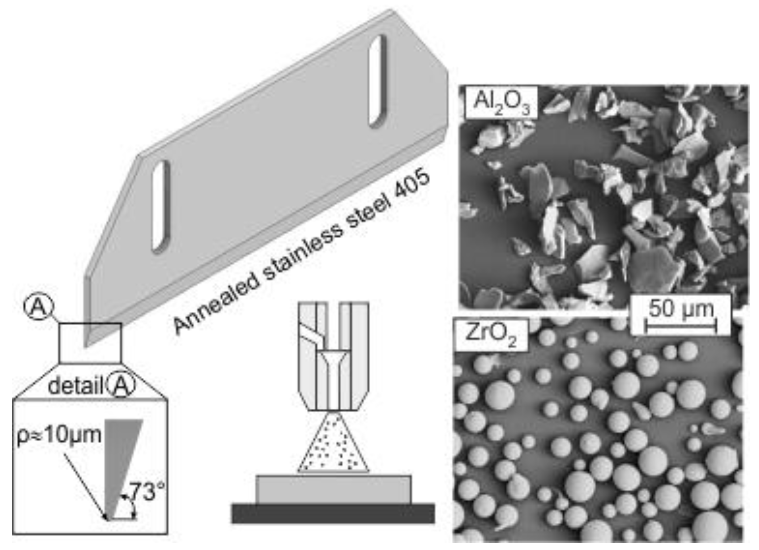
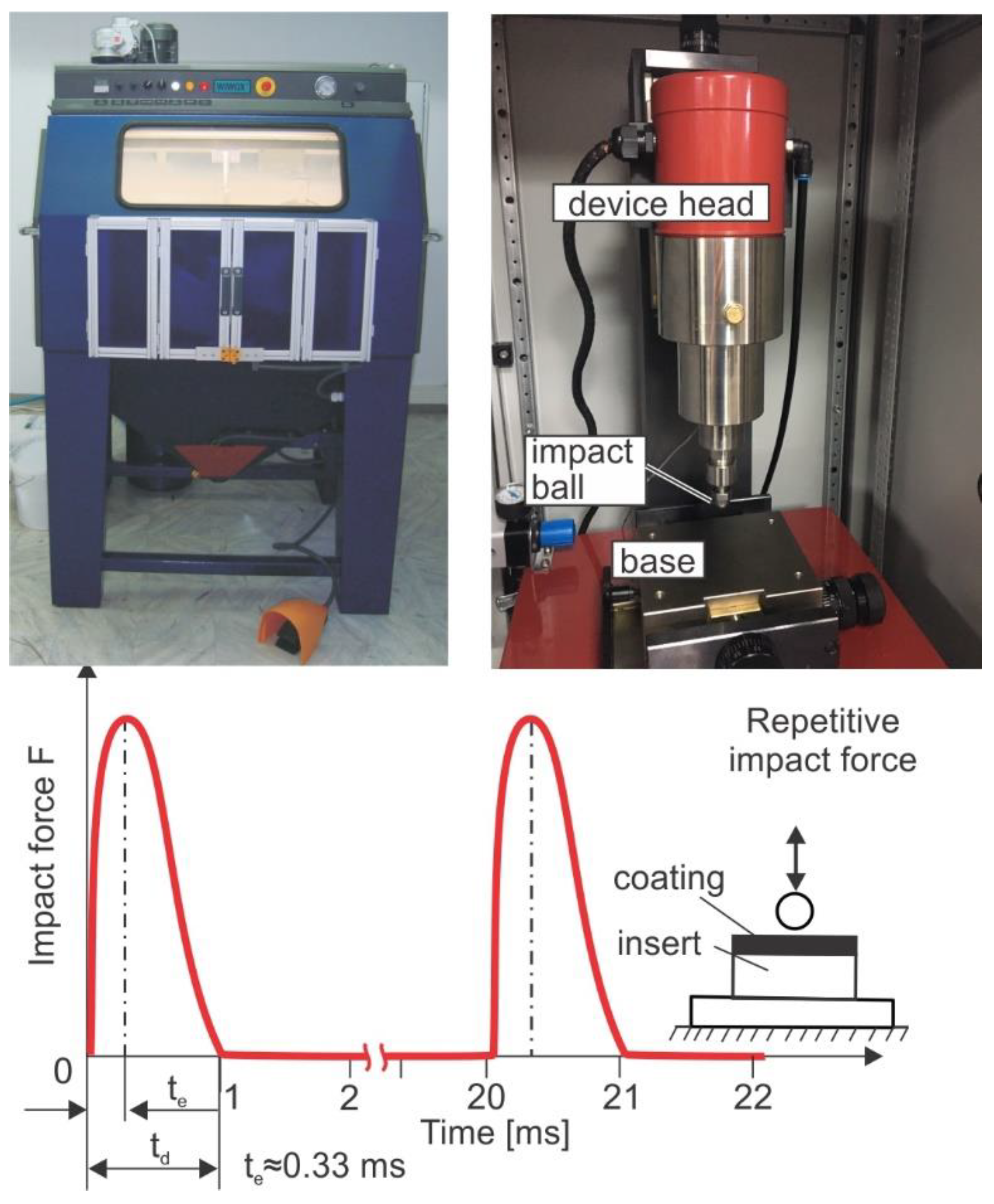
2.1. The Used Tools and the Employed Devices

The geometry of the tools employed for cheese cutting is illustrated in Figure 1. The tools were made of annealed stainless steel 405. The radius of the cutting edge was measured using white light scanning by a 3D confocal system mSURF of NANOFOCUS AG [1], and amounted to 10 μm. Dry micro-blasting was carried out on tools using sharp-edgedAl2O3 or spherical ZrO2 grains, as illustrated in the same figure. The average grain size was 10 μm. Due to the different grains’ geometry, the cutting edge topomorphy was expected to be variously affected.
The dry micro-blasting process was conducted using the WIWOX DI12SF located in the Laboratory for Machine Tools and Manufacturing Engineering of the Aristotle University of Thessaloniki (see Figure 2). All the micro-blasting parameters were kept constant except for the pressure. More specifically, the micro-blasting duration was equal to 4 s, the distance between the blasting nozzle and the tools was set to 100 mm, and the applied pressure amounted to 0.1 or 0.2 MPa. For determining the mechanical properties of the employed materials, nanoidentations were conducted by a FISCHERSCOPE H100 device (Helmut Fischer GmbH, Sindelfingen, Germany). The fatigue properties of the untreated and micro-blasted tools were assessed by perpendicular impact tests using an impact tester designed and manufactured by the Laboratory for Machine Tools and Manufacturing Engineering of the Aristotle University of Thessaloniki in collaboration with the company Impact-BZ (London, UK) [22]. The employed ceramic ball had a diameter of 5 mm. The applied time-dependent force signal is shown in Figure 2. Three-dimensional measurement facilities of the confocal microscope SURF of NANOFOCUS AG (Oberhausen, Germany) were used for evaluating the impact imprints. ANSYS 2021 R1 software was used for simulating the nanoindentation and impact tests and thus to determine the tool’s mechanical properties [1].

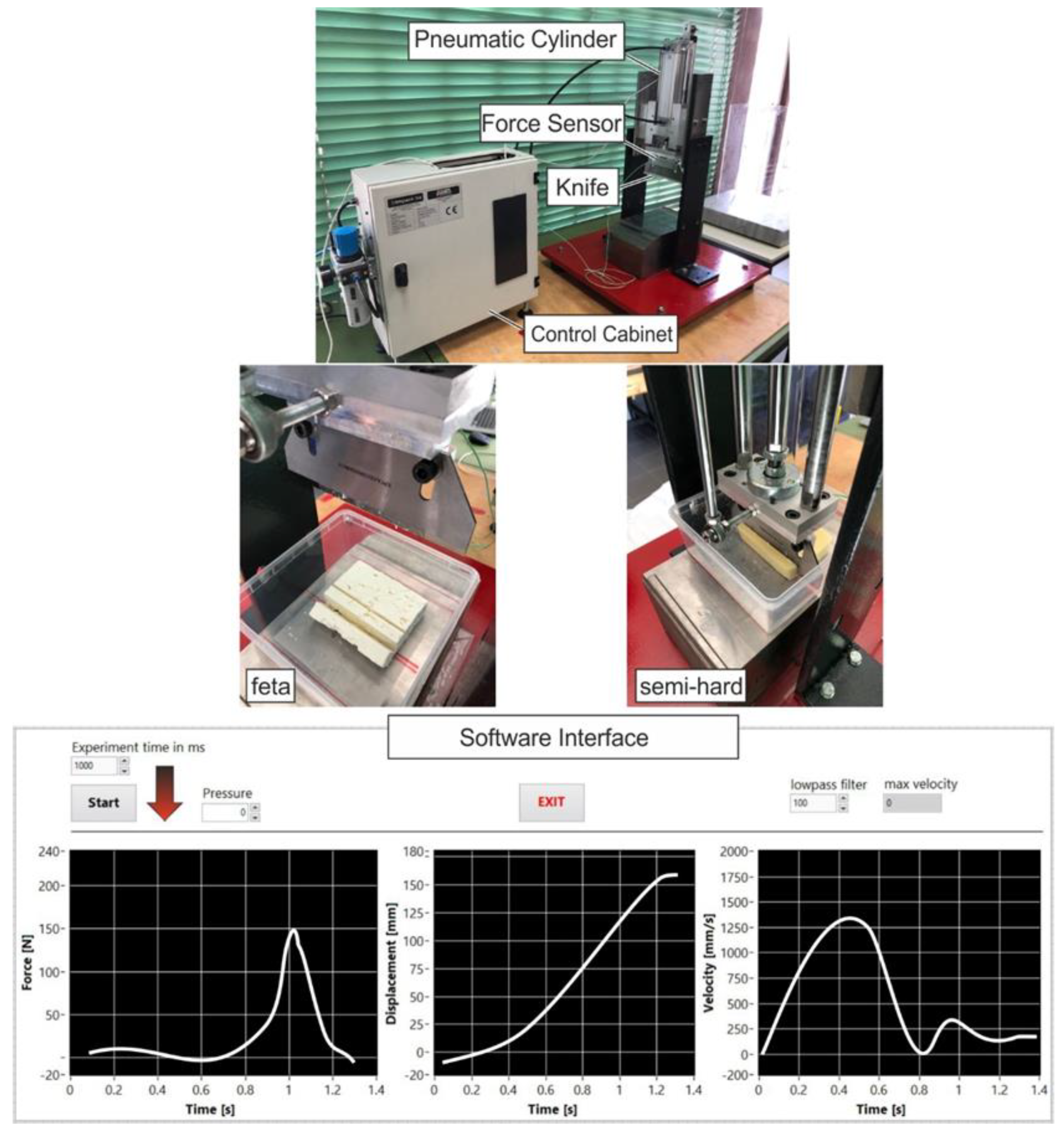
2.2. The Developed Device for Cheese Cutting

For conducting cutting experiments on cheese possessing different hardness, an experimental device was designed and manufactured by the Laboratory for Machine Tools and Manufacturing Engineering (LMTME) of the Mechanical Engineering Department at the Aristotle University of Thessaloniki (see Figure 3). The cutting mechanism consists of a cylindrical shaped piston that uses air pressure in order to move the cutting knife up and down. For stabilizing the device, two high-rigidity beams were used, in which there is the possibility of moving the piston mechanism according to the needs of the experiment. The maximum knife’s displacement is approximately 160 mm. In this way, cheese with different geometries can be cut. Between the piston and the cutting knife, a force measurement sensor was set in order to directly record the cutting force of the cheese. The operation of the developed device was controlled and monitored by a suitably developed algorithm using commercial computer software (Labview 8.6), thus enabling its fully automated operation. More specifically, the analog signal of the measurement device was turned into digital through an AT converter. The digital control, the data processing, the recording, and the results presentation were achieved through a developed algorithm using “Labview” software (8.6). Typical registered results, such as force, displacement, and velocity versus the experimental time taken from the developed software are presented at the bottom of Figure 3.

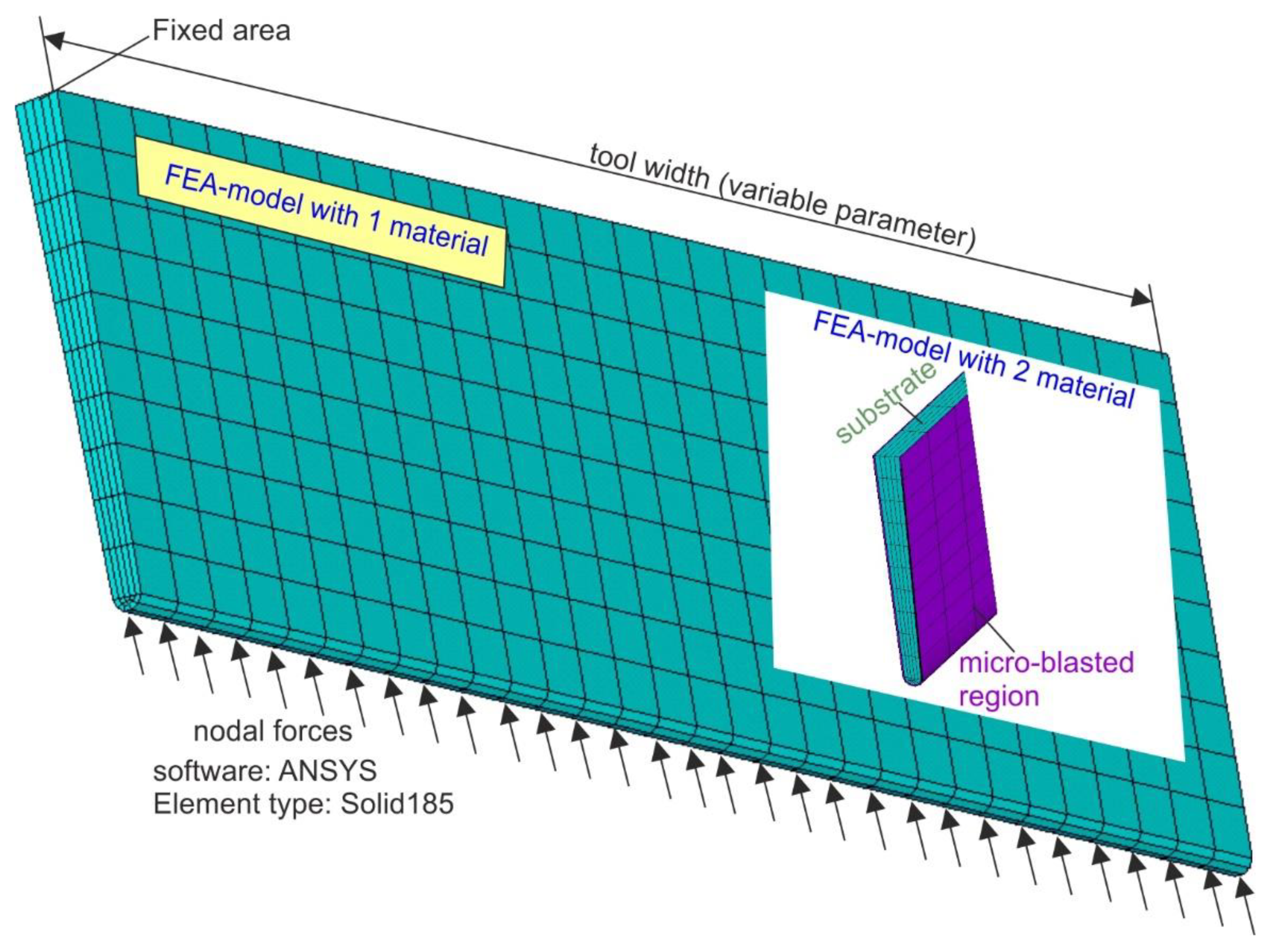
2.3. The Developed 3D-FEA Models for Simulating Cheese Cutting

Three-dimensional FEA models were developed using ANSYS 2021 R1 software for simulating the cheese-cutting process when untreated tools and micro-blasted ones were employed, as shown in Figure 4. The kinematic hardening rule was applied in the developed FEA model due to the fact that it leads to a rapid convergence in the corresponding FEM calculations [23].
The kinematic hardening assumes that the yield surface remains constant in size and the surface translates in stress space with progressive yielding, whereas the Besseling model is used [24], also called the sub-layer or overlay model, to characterize the material behavior. In the case of the micro-blasted tool, a second material area was considered to possess the mechanical properties and the width of the deformed region of a micro-blasted tool, as will be described in the next session. A rigid film–substrate interface was considered in the case of the coated tool. The geometry of the tool was similar to that one depicted in Figure 1. The width of the tool was equal to the contact region between the cheese and the tool. Convergence studies were conducted to determine the optimal mesh density and attain a mesh-independent grid. Solid elements possessing a pyramid geometry were used for generating the meshed volume. In order to simulate the cheese cutting, perpendicular nodal forces were applied to the cutting-edge region until the calculated reaction loads in the fixed upper area were equal to the measured one. The mechanical properties of the employed materials were set accordingly to the extracted results shown in the next sessions. The materials’ mechanical behavior was simulated as an isotropic using multilinear laws. With the aid of the developed FEA models, the developed maximum stresses corresponding to certain impact forces can be calculated in the case of untreated tools and micro-blasted ones.

3. Results

3.1. Hardness Characterization of the Untreated and Micro-Blasted Tools

Nanoindenation measurements were carried out to characterize the hardness of the examined materials using a Berkovich diamond indenter. The maximum indentation force was selected to be 15 mN in order to capture the effect of the micro-blasting process on superficial hardness modifications. The load–displacement diagrams of the untreated and micro-blasted tools at various pressures are illustrated in Figure 5a. To exclude the roughness effect on results accuracy, 30 measurements per nanoindentation were conducted. In this way, the moving average of the indentation depth versus the indentation force was stabilized [1]. As observed in both micro-blasting grain cases, an increase in the pressure was associated with a reduction of the maximum indentation depth. The latter is an indication that there is a hardness augmentation after micro-blasting. This fact can be explained by considering the induced residual stresses in the material structure after micro-blasting and the resulting superficial material deformation. The effect of the different employed grains on the material hardness is more clearly visible in Figure 5b, where the course of maximum indentation force versus the micro-blasting pressure is shown. According to the attained results, the registered maximum indentation depths were comparably larger in the case of ZrO2 grains under the same conditions. More specifically, the pristine maximum indentation depth amounted to 230 nm. After micro-blasting, the attained indentation depths at a pressure of 0.1 MPa were equal to 222 nm and 218 nm when Al2O3 and ZrO2 were employed, respectively. Moreover, the increase in material hardness at higher micro-blasting pressure was not so intense since there was a limit to the induced residual stresses that a material can receive prior to its fracture.
In order to interpret the previous shown results, roughness measurements were conducted on variously micro-blasted tools. A characteristic roughness magnitude for showing the effect of different employed grains on surface integrity was the maximum peak to valley height Rt. Since Rt shows the height difference between the highest mountain and lowest valley within the measured range, potential superficial cracks created due to the grains’ impact can be captured. The related results are shown in Figure 6. Each bar shown in this figure represents the mean value of 10 measurements. As can be observed in Figure 6, the roughness Rt became more intense when Al2O3 grains were used. This can be explained by considering the geometries of the used grains. Due to their sharp edges, a part of the initial kinetic energy of the Al2O3 grains was consumed to micro-chipping on the material surface, and in this way, the roughness increased. On the contrary, in the case of ZrO2 grains, a bigger portion of the initial kinetic energy was used for material deformation and as a consequence, larger indentation depths were attained.

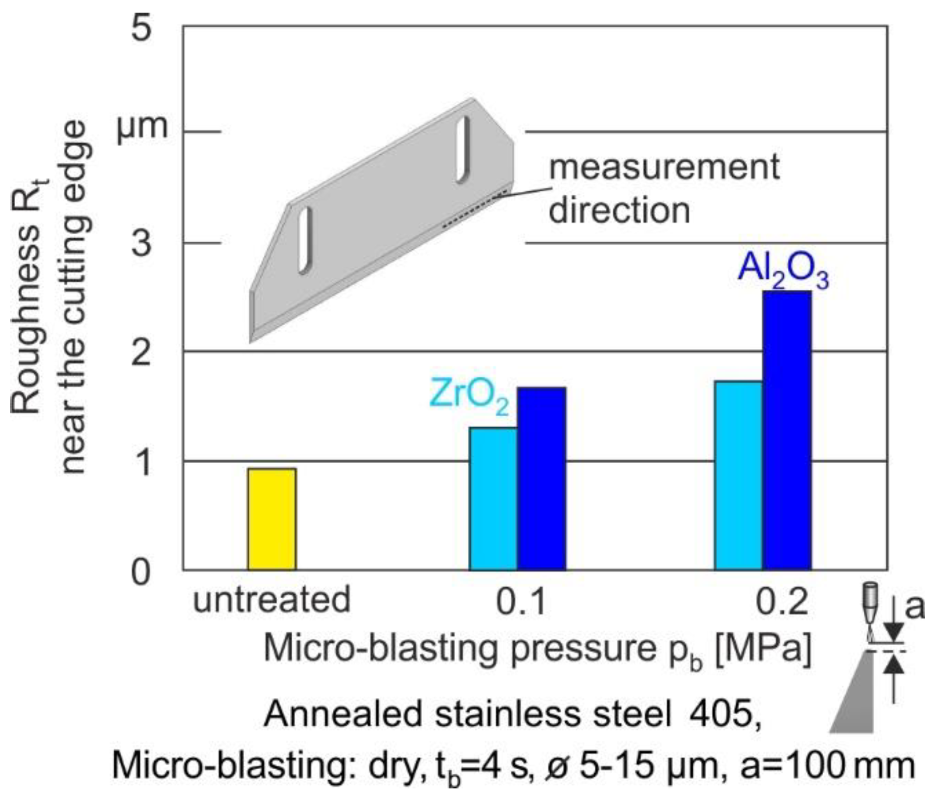
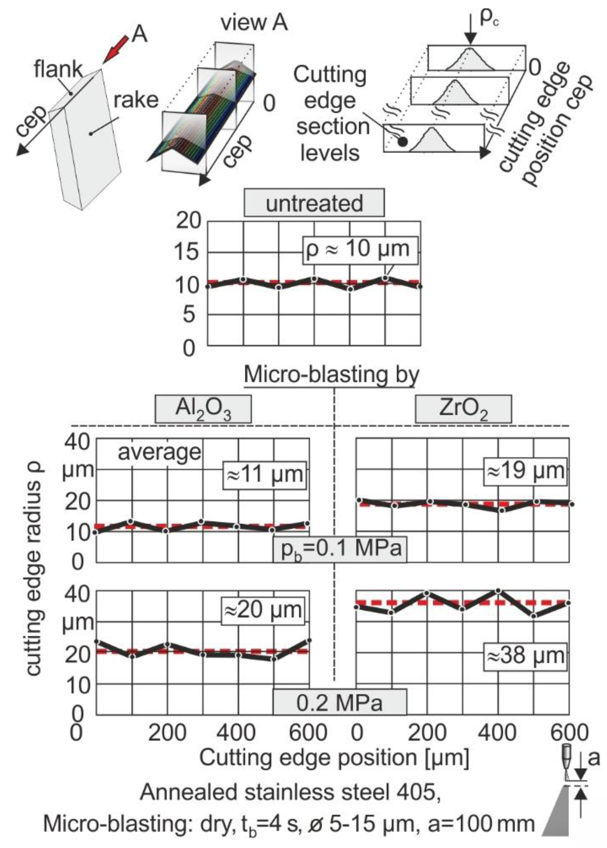
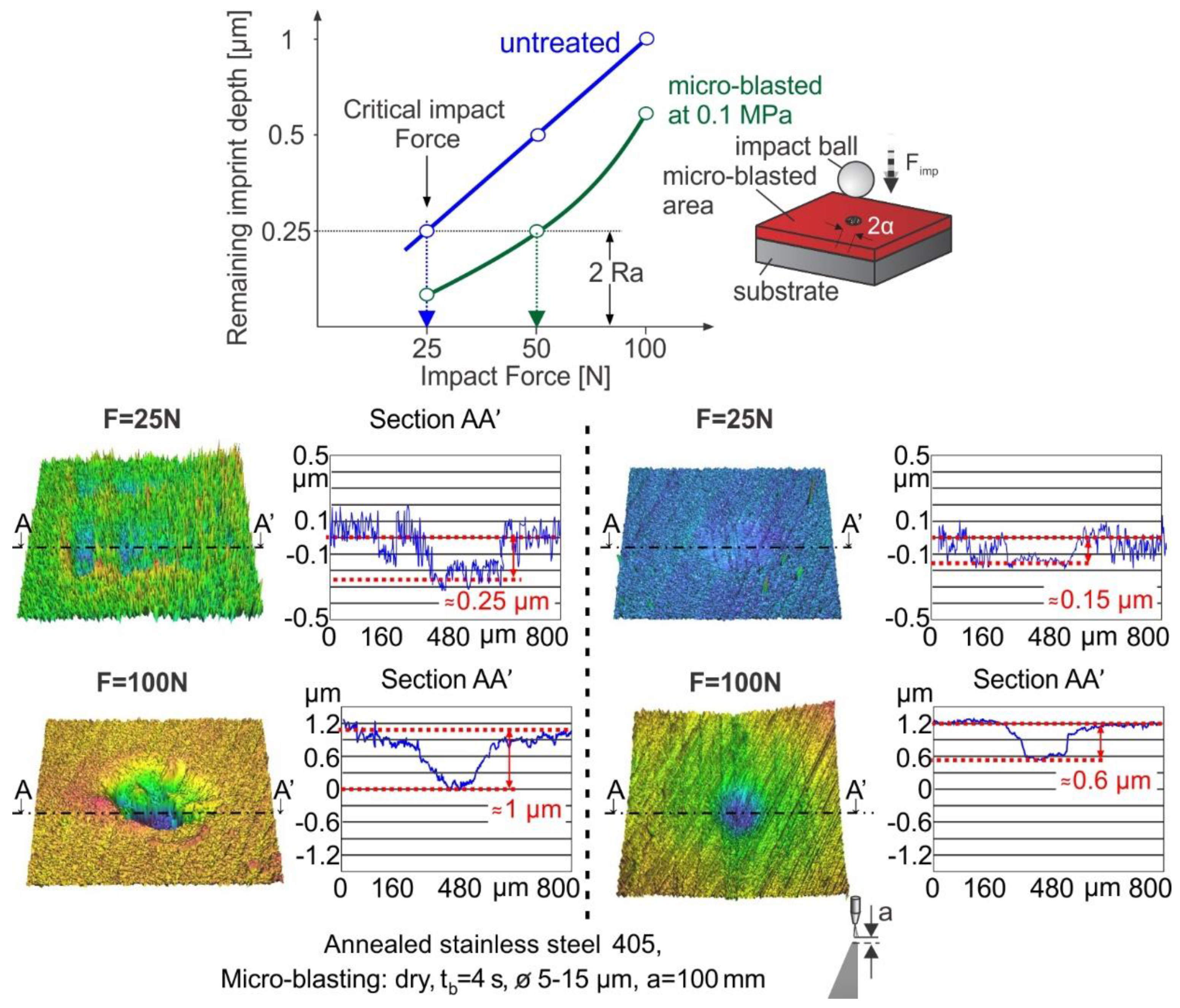
3.2. Cutting Edge Radius of the Untreated and Micro-Blasted Tools

A crucial issue for the effective application of tools in a cheese-cutting machine is the magnitude of their cutting-edge radii. This is attributed to the fact that the sharpness of the tool plays a dominant role in maintaining the surface integrity of the cheese after its cutting, which is desired to be as smooth as it can be. Although micro-blasting has been reported to be an efficient method for improving material hardness, it causes an enlargement of the cutting-edge radius [18]. In order to determine the variation of the cutting-edge radius of the micro-blasted tools, confocal microscopy measurements were carried out. The related results are shown in Figure 7. More specifically, it was necessary to register successive cross-sections of the cutting edges and to determine the average values (see Figure 7). The pristine cutting-edge radius of the untreated tools amounted to 10 μm. The conduct of micro-blasting resulted in an enlargement of the cutting-edge radius. Only in the case of Al2O3 grains and when the micro-blasting amounted to 0.1 MPa did this magnitude remain almost invariable. Based on these results, an optimum micro-blasting pressure of 0.1 MPa with Al2O3 grains was selected for improving the tool life.

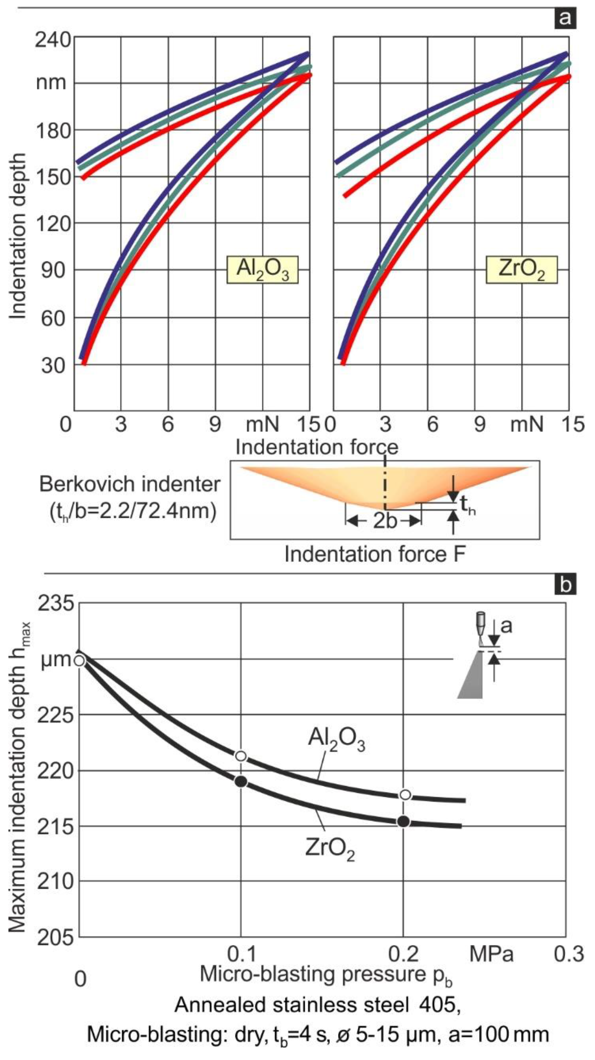
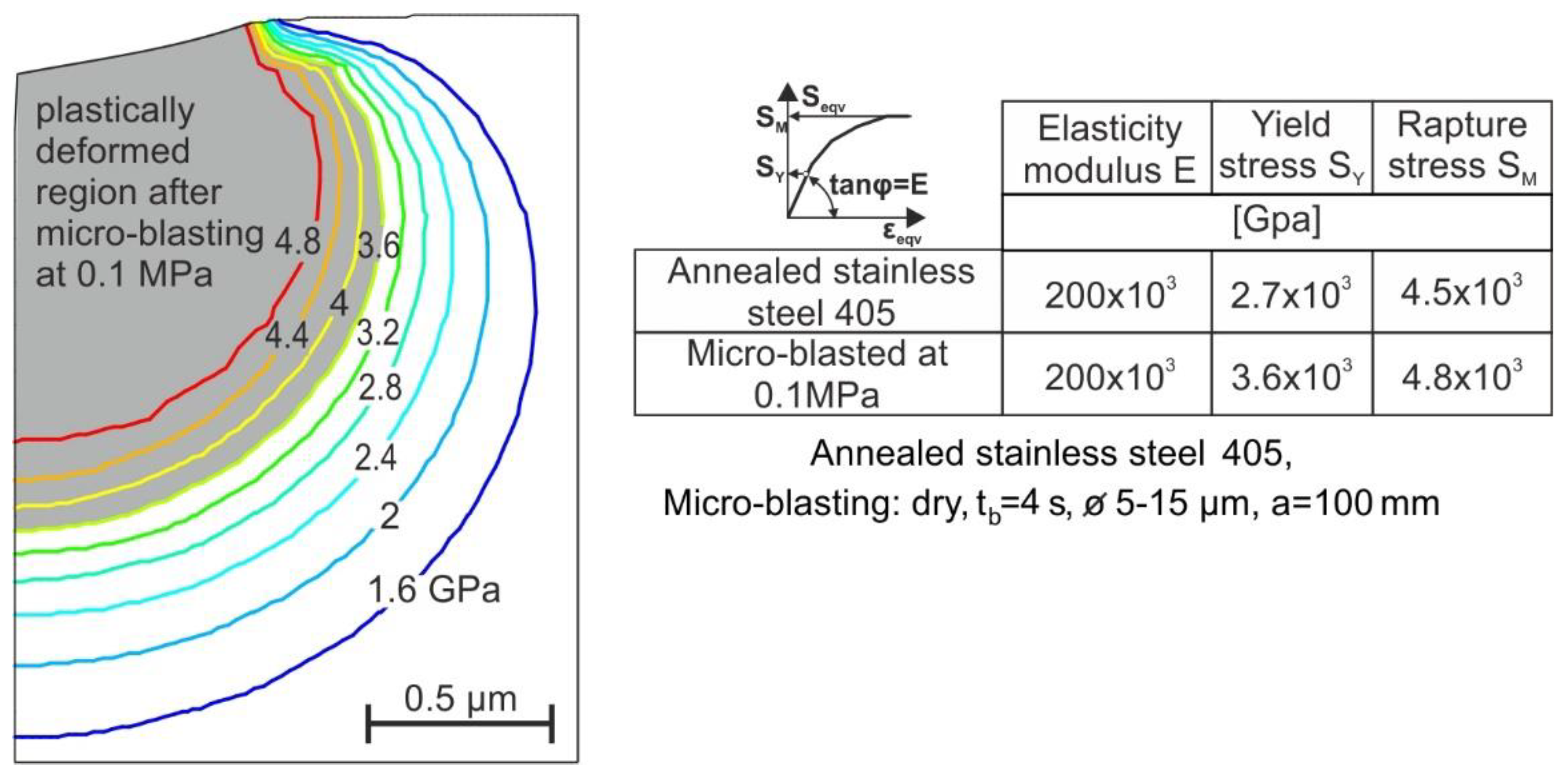
3.3. Mechanical Properties of the Untreated and Micro-Blasted Tools

For determining the mechanical properties of the untreated and micro-blasted tools at a pressure of 0.1 MPa, the FEM-based procedure concerning the stepwise simulation of the nanoindentation procedure, based on the SSCUBONI algorithm, was employed [1]. It has to be pointed out that only in these two cases the cutting-edge radii were almost equal, and the tools preserved their sharpness. In this way, using the nanoindentation results diagrams shown in Figure 5a, the input data to the developed algorithm was created, and the mechanical properties of the investigated materials were extracted. These results are illustrated in Figure 8. As observed, the elasticity modulus remained unaffected by the micro-blasting process, whereas the yield and rupture stress grew. Generally, micro-blasting results in a gradation of the strength properties [25]. In the described investigations, for simplifying the related calculations, it was assumed that evenly distributed strength properties develop up to a certain depth from the film surface. By applying the technique described in ref. [25], the occurring equivalent stress distribution during micro-blasting can be determined, and the width of the shadowed area associated with the plastically deformed region can be calculated. These data were employed in the developed FEA model, simulating the cheese-cutting process for determining the maximum developed stresses.
Furthermore, perpendicular impact tests were conducted at various impact loads in order to detect the critical ones for fatigue damage initiation in the case of untreated and micro-blasted tools. Related results in terms of the remaining imprint depths at various exercised loads after 106 impacts on annealed stainless steel 405 and the micro-blasted ones at a pressure of 0.1 MPa are shown in the diagram of Figure 9. To avoid the interpretation of surfaces asperity damages as material damage, the double of the tool’s arithmetic roughness Ra was considered as a criterion for material fracture. According to the attained results, the critical impact loads for exceeding the above-mentioned criterion were 25 N and 50 N for the annealed stainless steel 405 and the micro-blasted ones, respectively. Characteristic impact imprints at various loads in the case of stainless steel 405 and the micro-blasted ones, scanned by white light via confocal microscopy, are shown in the bottom part of the figure.
Based on a FEM simulation of the impact process [1] and considering the results shown in Figure 9, the Smith-like diagrams and the Woehler diagrams of an annealed stainless steel 405 and the micro-blasted ones were determined and are illustrated in Figure 10. The Smith diagram presents the maximum load alterations versus its mean value for a fatigue-safe operation of stressed material. The Woehler diagram illustrates the fatigue-safe maximum stress versus the number of repetitive loads alternating from zero to a maximum value. Since the developed stresses during the operation of the cheese cutting tool alternate from zero up to a maximum value, the latter diagram can be used for predicting the number of impacts that the tool can receive during cheese cutting before its fatigue fracture initiation.

3.4. Cutting Results

The experiments were carried out on two different types of cheese concerning its hardness (feta cheese and semi-hard cheese), as illustrated in Figure 11. The effect of cheese hardness on the developed forces is clearly visible. Every curve represents the mean value of approximately 20 experiments. For the semi-hard cheese, a cutting force of about 220 N is required, while for the feta cheese, only 100 N is needed. According to the conducted force measurements of cheeses with different heights, the maximum developed force remains practically invariable from the cheese geometry, and it depends only upon its hardness. Moreover, the knife’s displacement and the velocity of the piston were measured, as shown in the bottom part of the figure. It is obvious that the measurements are almost identical for both types of cheese. The whole cutting process for a knife displacement of 160 mm lasts approximately less than 250 ms. Thus, dynamic loads are developed on the cutting edge of the knife during the repetitive cuts, leading to the initiation of fatigue failure after a certain number of cuts.

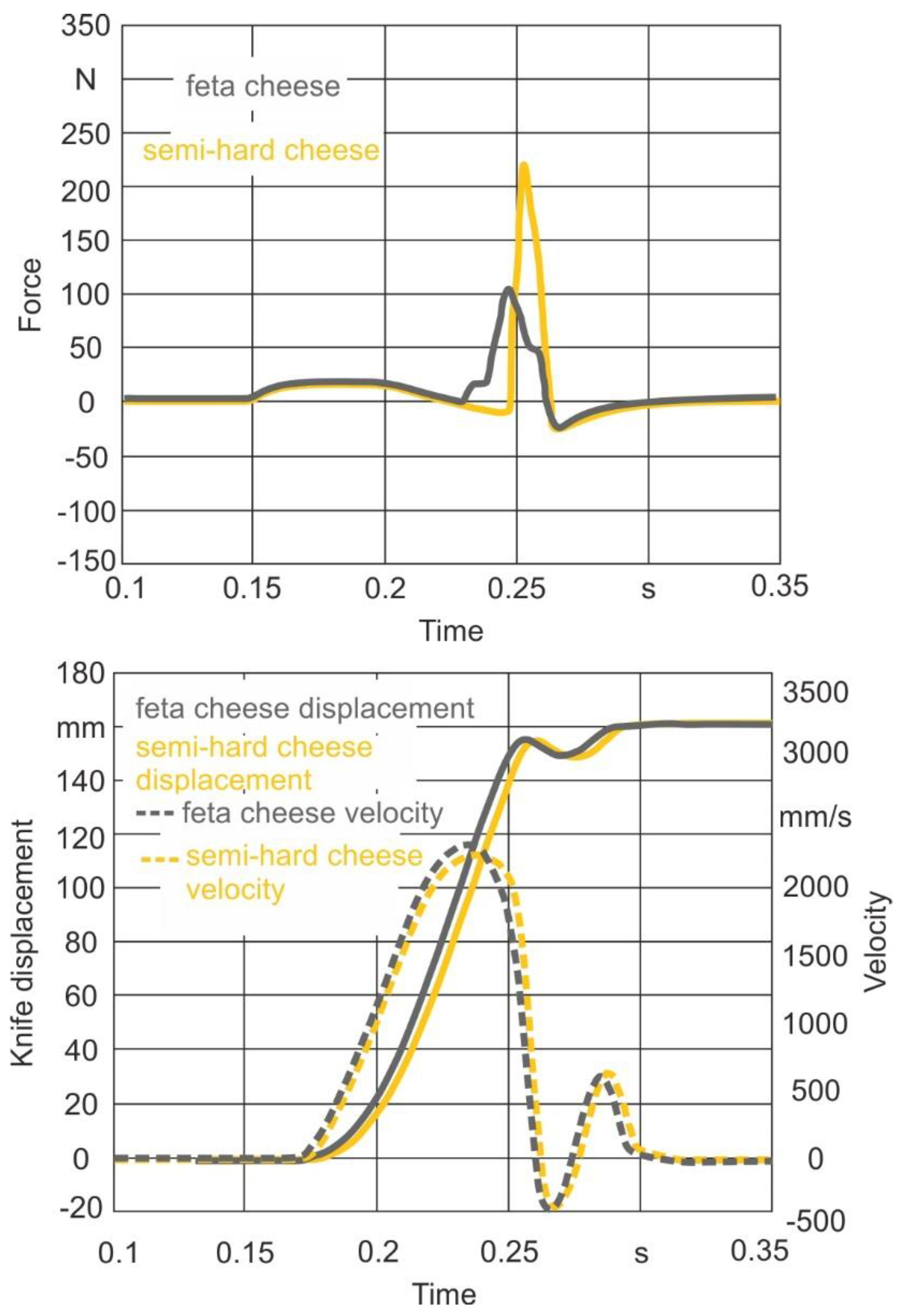
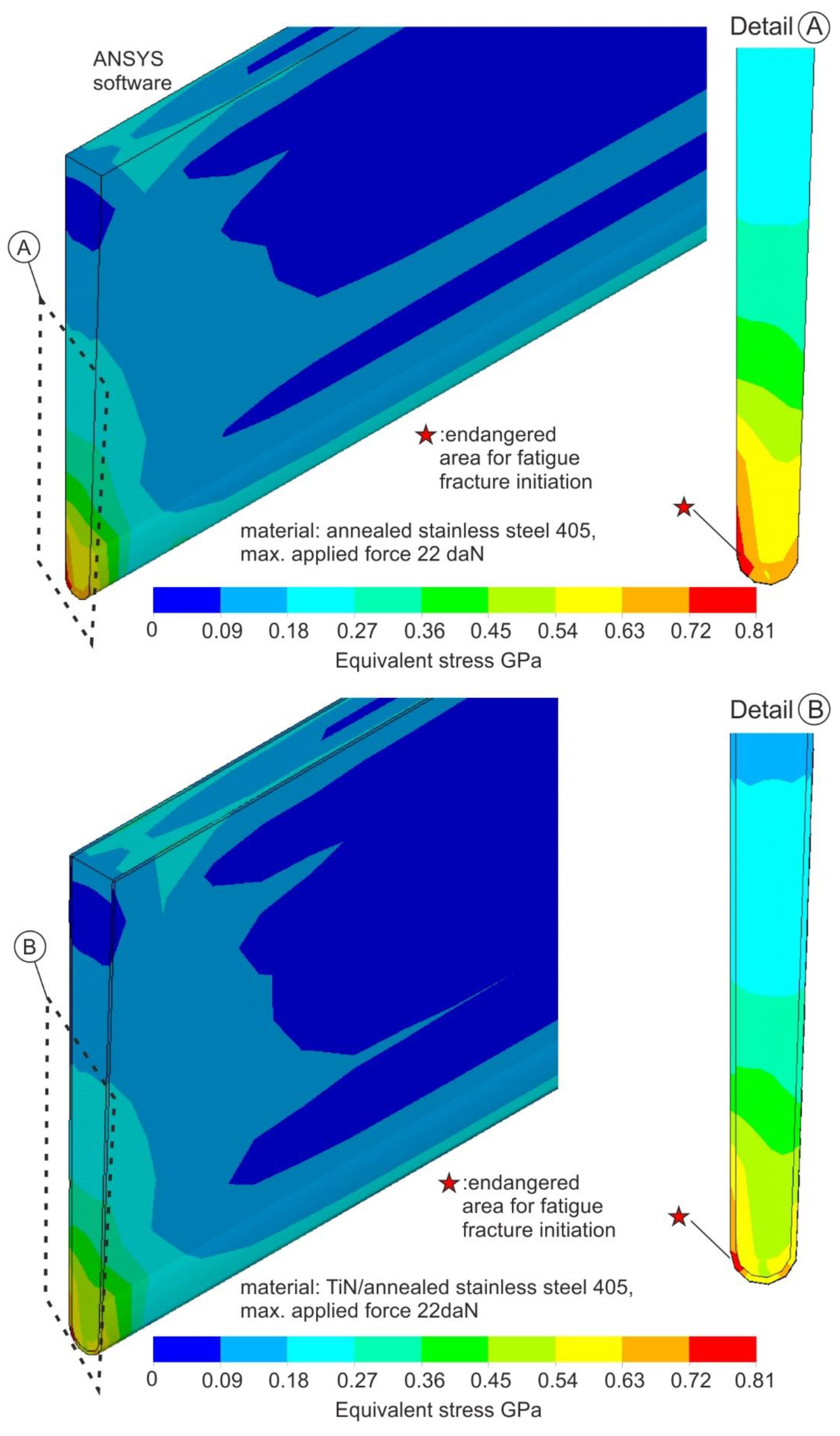
3.5. FEA Results during Cheese Cutting

Βy employing the aforementioned FEA models (see Figure 4), the developed equivalent stress fields in the tools during cheese cutting associated with the most intense loading case of semi-hard cheese were determined. The related results for both uncoated and micro-blasted tools are shown in Figure 12. The maximum stress in both cases amounts to 0.81 GPa. This stress is developed in the right part of the tool. This fact can be explained by the cutting-edge geometry (see Figure 1). More specifically, in this region, due to its geometry, higher bending stresses are developed, resulting in a more intense tool loading. Although the maximum equivalent stress does not exceed the material yield stress in both cases, it is higher than the critical fatigue endurance stress. As a consequence, a fatigue damage initiation is expected after approximately 200,000 impacts in the case of the uncoated tool (see Figure 13). Moreover, the application of micro-blasting at 0.1 MPa results in a significant augmentation of the number of impacts that the tool can withstand up to the fatigue fracture initiation. As can be observed in Figure 13, the first coating fracture occurred after approximately 700,000 impacts.

4. Discussion

In the food industry, the production of standard pieces of cheese concerning its weight is a complicated process with high importance. In this context, cheese packages less than a certain weight are not accepted, whereas overweight packages are associated with an additional cost for industries. Moreover, the interruption of this process due to the failure of the cutting tool entails prolonged production time due to the replacement of worn tools and increased cost. In such a production process, the tools are commonly made of stainless steel, and they are subjected to dynamic loads during the cheese-cutting process. In this way, fatigue failure is the prevailing wear phenomenon, significantly reducing the tool life.
The importance of micro-blasting as a technique to increase the life span of tools has been registered in the past [18,19]. This process has as a target to induce residual stresses in the material structure and, in this way, to increase the mechanical properties [14]. As a consequence, the fatigue properties are also expected to be improved. However, this process has to be carefully applied concerning the selected conditions since it can modify the geometry of the cutting edge. In our previous publication [18], dry micro-blasting was conducted on TiAlN coatings deposited on cemented carbide inserts using Al2O3 or ZrO2 grains. These coatings were characterized by comparably superior mechanical properties. As a result, larger micro-blasting pressures must be applied to deform the coating structure and thus induce residual stresses. In the case of the coated tools described in ref. [18], an enlargement of the cutting-edge radius takes place as the micro-blasting pressure increases. A larger cutting-edge radius leads to a reduction of the developed stresses on the coated tool during cutting and to a simultaneous tool life increase [26]. However, special care must be taken to avoid substrate revelation due to coating abrasion in the cutting-edge region during micro-blasting. In the case of annealed stainless steel 405, the applied conditions must appropriately change to attain sufficient increases in the mechanical characteristics without enlarging the cutting-edge radius. This must occur since the sharpness of the tool plays a dominant role in ensuring the surface integrity of the cheese after its cutting, making it as smooth as it can be.
In this paper, for the first time, an experimental-analytical methodology was developed for selecting optimum micro-blasting conditions dependent upon the tool geometry and properties and for determining the number of impacts that the tool can withstand until the first fatigue fracture. Via the developed methodology, preventive replacement of the tool can be conducted, avoiding the risk of sudden tool failure. This methodology was applied in the case tools employed in cheese cutting. To verify the developed methodology’s capability to predict the number of impacts for fatigue damage initiation of the tool, cutting experiments were conducted using a semi-hard cheese as the workpiece material (see Figure 14). The tool possesses the geometry as illustrated in Figure 1, and it is made of annealed stainless steel 405. According to attained results, after 200,000 impacts, there was no sign of failure, and fatigue cracks appeared after the conduct of further 10,000 impacts, resulting in tool material removal. These results are in good agreement with the calculated ones. Thus, the capability of the developed methodology to predict the critical number of impacts for tool replacement is verified. The issue of the tool replacement prior to its fatigue fracture is very important. Despite the cheese cleanness process after the production of standard pieces of cheese concerning weight, the whole process became more secure since any possibility of fragmented metallic parts of the tool being inserted into the cheese was avoided. Another significant issue in the market is the surface integrity of the cheese region that must be cut. By assuring an unworn cutting-edge geometry of the tool, the surface integrity of the cheese is expected to be improved, and wasted material during cutting is predicted to be minimized.

5. Conclusions

In the present work, the potential to enlarge the life span of tools applied in a cheese cutting machine via micro-blasting was investigated. Optimum micro-blasting conditions were detected, considering an almost invariable cutting-edge radius as a criterion. Moreover, a methodology was developed for predicting the number of impacts that the tool can receive during cheese cutting before its fatigue fracture initiation. This methodology was based on the construction of a pneumatic system for the precise cutting of cheese and the simultaneous measurement of the forces developed, as well as on appropriate FEA modeling. The following basic conclusions can be summarized:
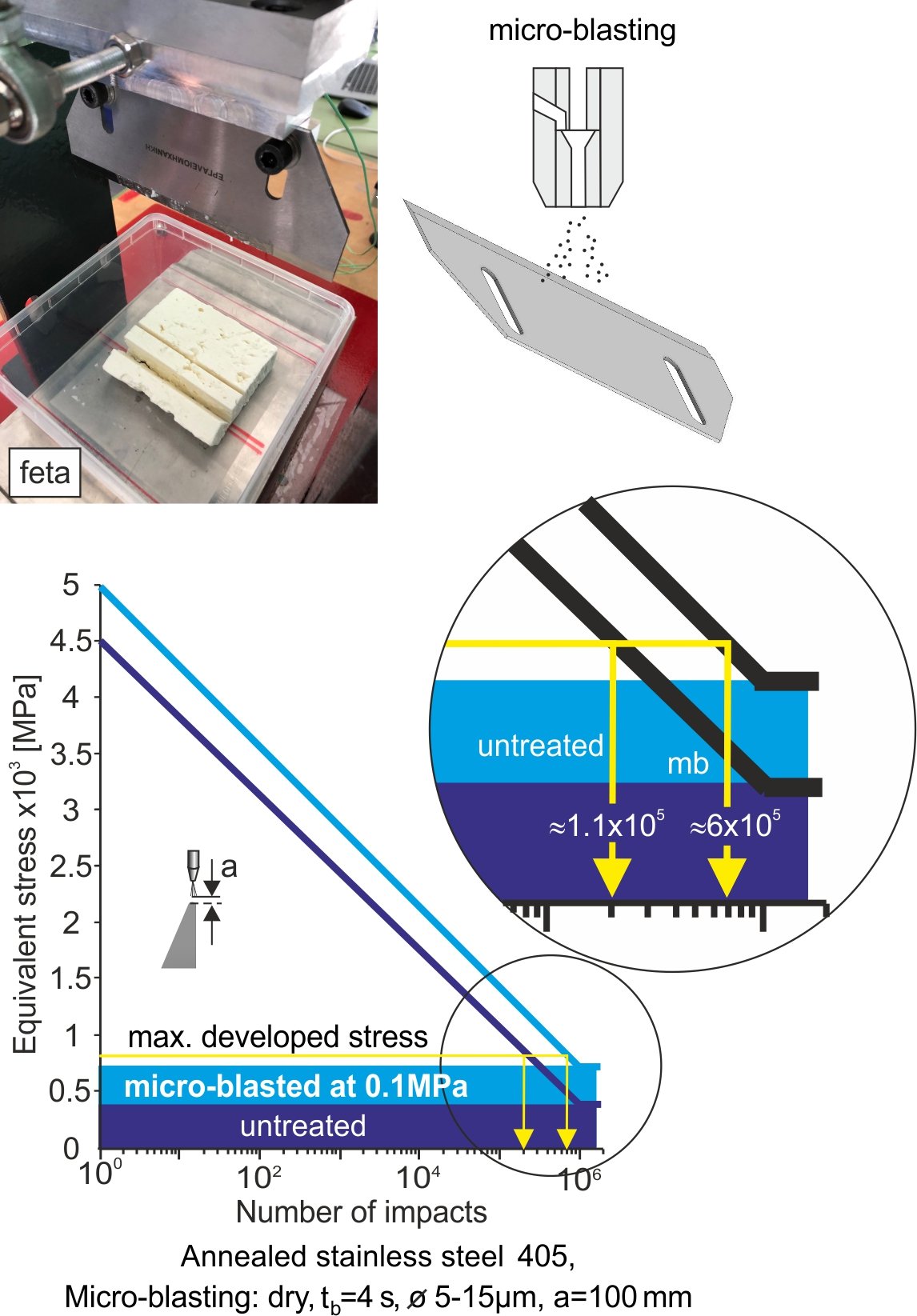
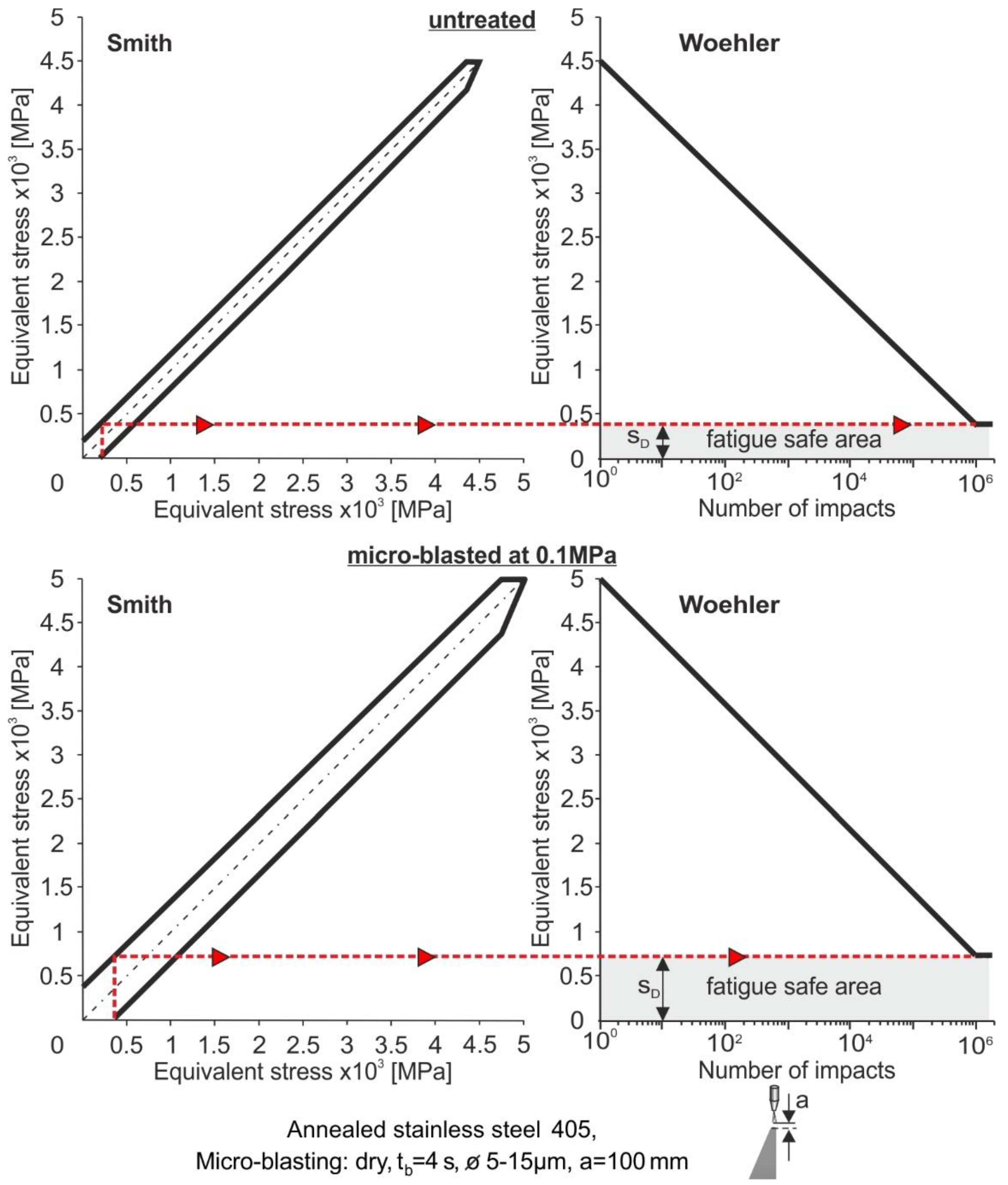
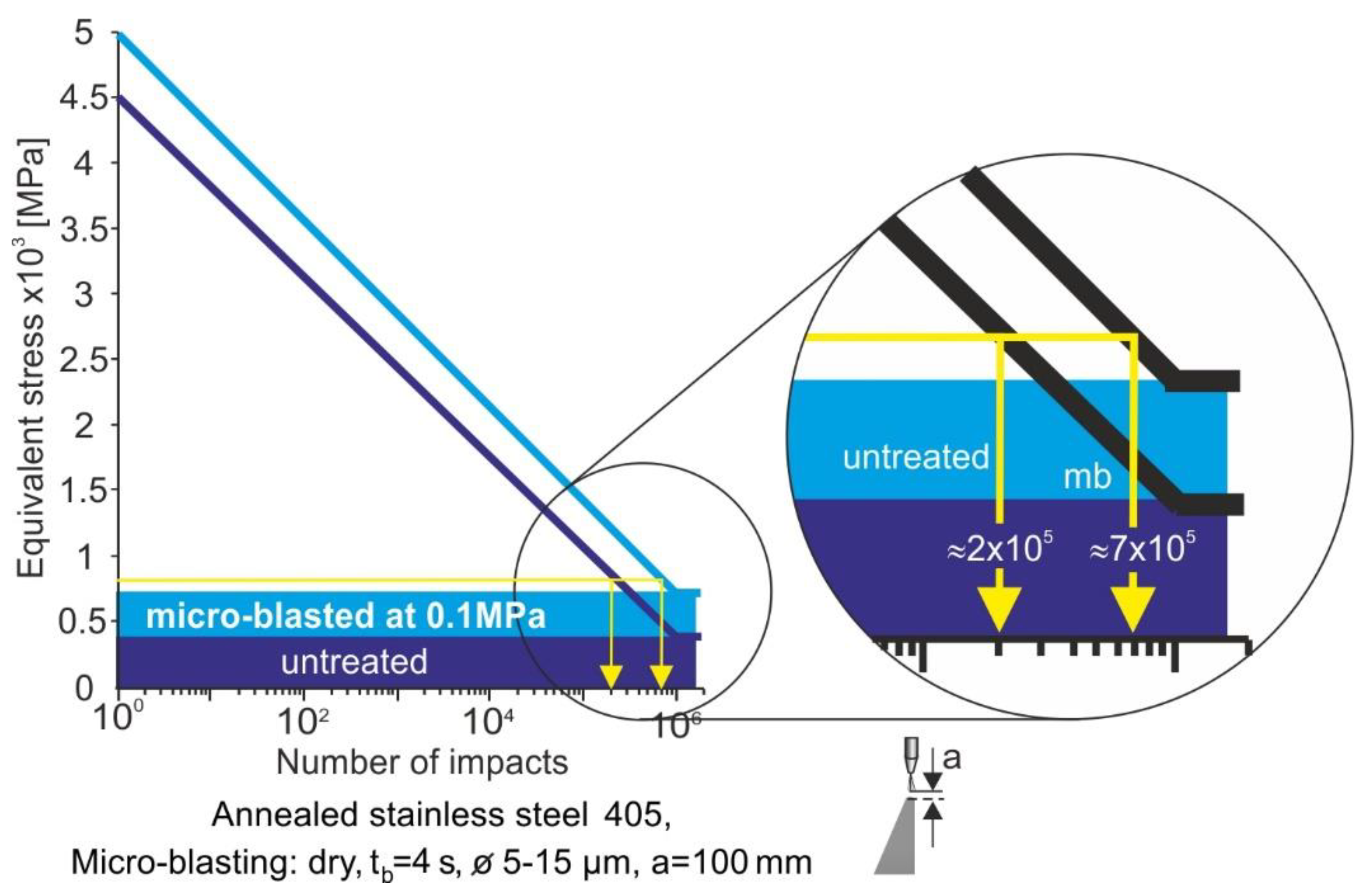
  • The conduct of dry micro-blasting at a pressure of 0.1 MPa using Al2O3 grains can increase the number of impacts that the tool can withstand, more than three times, until the fatigue fracture initiation.
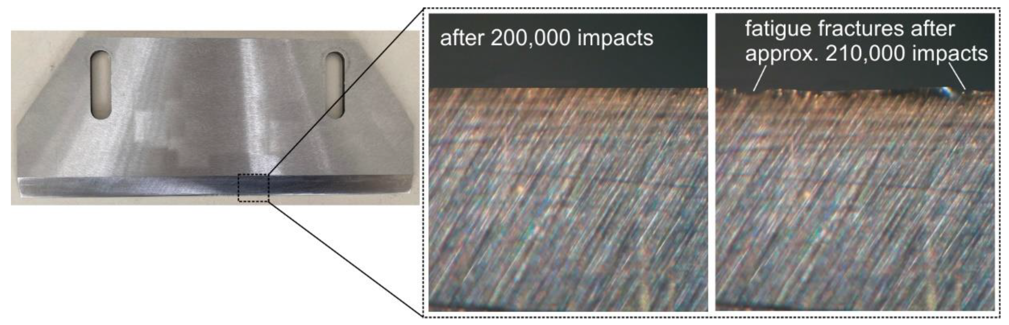
  • Experimental cutting investigations on semi-hard cheese using an untreated tool verify the capability of the developed methodology to predict the critical number of impacts for fatigue damage imitation.
  • The proposed methodology can be applied to different tool geometries and materials since a parametric FEA model was developed.
  • The issue of the tool replacement prior to its fatigue fracture is very important. Despite the cheese cleanness process after the production of standard pieces of cheese concerning weight, the whole process became more secure since any possibility of damaged parts being inserted into the cheese was avoided. Moreover, by assuring an unworn cutting-edge geometry of the tool, the surface integrity of the cheese was expected to be improved, and wasted material during cutting was minimized.

Author Contributions

Conceptualization, G.S.; methodology, G.S.; software, G.S., I.M., K.V. and L.K.; validation, G.S, K.V., L.K., I.M., V.P. and S.P.; formal analysis, G.S., I.M., K.V., and L.K.; investigation, G.S, K.V., L.K., I.M., V.P. and S.P.; data curation, G.S. and S.P.; writing—original draft preparation, G.S.; writing—review and editing, G.S.; visualization, G.S.; supervision, G.S.; project administration, G.S. and S.P.; All authors have read and agreed to the published version of the manuscript.

Funding

This research was carried out as part of the project «DESIGN, DEVELOPMENT & OPTIMIZATION OF AN INNOVATIVE CHEESE CUTTING MACHINE» (Project code: KMP6-0077379) under the framework of the Action «Investment Plans of Innovation» of the Operational Program «Central Macedonia 2014 2020», that is co-funded by the European Regional Development Fund and Greece.

Institutional Review Board Statement

Not applicable.

Informed Consent Statement

Not applicable.

Data Availability Statement

Not applicable.

Conflicts of Interest

The authors declare no conflict of interest.

References

  1. Bouzakis, K.-D.; Michailidis, N.; Skordaris, G.; Bouzakis, E.; Biermann, D.; M’Saoubi, R. Cutting with coated tools: Coating technologies, characterization methods and performance optimization. CIRP Ann. Manuf. Technol. 2012, 61, 703–723. [Google Scholar] [CrossRef]
  2. Xiaowei, L.; Hanlin, W.; Liuyang, F.; Huiyong, B. Low-cycle fatigue behavior for stainless-clad 304 + Q235B bimetallic steel. Int. J. Fatigue 2022, 159, 106831. [Google Scholar]
  3. Knotek, O.; Bosserhoff, B.; Schrey, A.; Leyendecker, T.; Lemmer, O.; Esser, S. A New Technique for Testing the Impact Load of Thin Films: The Coating Impact Test. Surf. Coat. Technol. 1992, 54–55, 102–107. [Google Scholar] [CrossRef]
  4. Gothivarekar, S.; Coppieters, S.; Talemi, R.; Debruyne, D. Effect of bending process on the fatigue behaviour of high strength steel. J. Constr. Steel Res. 2021, 182, 106662. [Google Scholar] [CrossRef]
  5. Bin, Z.; Ali, H.; Xiaoman, Z.; Jikui, Z.; Shao, S.; Khonsari, M.M.; Guo, S.; Meng, W.J. On the failure mechanisms of Cr-coated 316 stainless steel in bending fatigue tests. Int. J. Fatigue 2020, 139, 105733. [Google Scholar]
  6. Guodong, W.; Yafei, M.; Zhongzhao, G.; Hanbing, B.; Lei, W.; Jianren, Z. Fatigue life assessment of high-strength steel wires: Beach marks test and numerical investigation. Constr. Build. Mater. 2022, 323, 126534. [Google Scholar]
  7. Skordaris, G.; Bouzakis, K.-D.; Charalampous, P.; Kotsanis, T.; Bouzakis, E.; Bejjani, R. Bias voltage effect on the mechanical properties, adhesion and milling performance of PVD films on cemented carbide inserts. Wear 2018, 404–405, 50–61. [Google Scholar] [CrossRef]
  8. Yu, W.; Yin, Y.; Zhou, J.; Xu, Q.; Feng, X.; Nan, H.; Zuo, J.; Wang, X.; Ding, X. Surface Condition Evolution and Fatigue Evaluation after Different Surface Processes for TiAl47Cr2Nb2 Alloy. Materials 2022, 15, 5491. [Google Scholar] [CrossRef]
  9. Avcu, Y.Y.; Gönül, B.; Yetik, O.; Sönmez, F.; Cengiz, A.; Guney, M.; Avcu, E. Modification of Surface and Subsurface Properties of AA1050 Alloy by Shot Peening. Materials 2021, 14, 6575. [Google Scholar] [CrossRef]
  10. Rautio, T.; Jaskari, M.; Gundgire, T.; Iso-Junno, T.; Vippola, M.; Järvenpää, A. The Effect of Severe Shot Peening on Fatigue Life of Laser Powder Bed Fusion Manufactured 316L Stainless Steel. Materials 2022, 15, 3517. [Google Scholar] [CrossRef]
  11. Matuszak, J.; Zaleski, K.; Skoczylas, A.; Ciecielag, K.; Kecik, K. Influence of Semi-Random and Regular Shot Peening on Selected Surface Layer Properties of Aluminum Alloy. Materials 2021, 14, 7620. [Google Scholar] [CrossRef] [PubMed]
  12. Wang, Z.; Shi, M.; Gan, J.; Wang, X.; Yang, Y.; Ren, X. The Effects of Shot Distance and Impact Sequence on the Residual Stress Field in Shot Peening Finite Element Model. Metals 2021, 11, 462. [Google Scholar] [CrossRef]
  13. Efe, Y.; Karademir, I.; Husem, F.; Maleki, E.; Karimbaev, R.; Amanov, A.; Unal, O. Enhancement in microstructural and mechanical performance of AA7075 aluminum alloy via severe shot peening and ultrasonic nanocrystal surface modification. Appl. Surf. Sci. 2020, 528, 146922. [Google Scholar] [CrossRef]
  14. Chung, Y.-H.; Chen, T.-C.; Lee, H.-B.; Tsay, L.-W. Effect of Micro-Shot Peening on the Fatigue Performance of AISI 304 Stainless Steel. Metals 2021, 11, 1408. [Google Scholar] [CrossRef]
  15. Barbatti, C.; Garcia, J.; Pitonak, R.; Pinto, H.; Kostka, A.; Di Prinzio, A.; Staia, M.H.; Pyzalla, A.R. Influence of micro-blasting on the microstructure and residual stresses of CVD j-Al2O3 coatings. Surf. Coat. Technol. 2009, 203, 3708–3717. [Google Scholar] [CrossRef]
  16. Jacob, A.; Gangopadhyay, S.; Satapathy, A.; Mantry, S.; Jha, B.B. Influences of micro-blasting as surface treatment technique on properties and performance of AlTiN coated tools. J. Manuf. Process. 2017, 29, 407–418. [Google Scholar] [CrossRef]
  17. Gadge, M.; Lohar, G.; Chinchanikar, S. A review on micro-blasting as surface treatment technique for improved cutting tool performance. Mater. Today Proc. 2022, 64, 725–730. [Google Scholar] [CrossRef]
  18. Bouzakis, K.-D.; Klocke, F.; Skordaris, G.; Bouzakis, E.; Gerardis, S.; Katirtzoglou, G.; Makrimallakis, S. Influence of dry micro-blasting grain quality on wear behaviour of TiAlN coated tools. Wear 2011, 271, 783–791. [Google Scholar] [CrossRef]
  19. Bouzakis, K.-D.; Tsouknidas, A.; Skordaris, G.; Bouzakis, E.; Makrimallakis, S.; Gerardis, S.; Katirtzoglou, G. Optimization of wet or dry microblasting on PVD films by various Al2O3 grain sizes for improving the coated tools’ cutting performance. Tribol. Ind. 2011, 33, 49–56. [Google Scholar]
  20. Astakhov, V.P. Cutting Force Modeling Genesis, State of the Art, and Development. In Mechanical and Industrial Engineering: Historical Aspects and Future Directions; Davim, J.P., Ed.; Springer Nature: Cham, Switzerland, 2022; pp. 39–93. [Google Scholar]
  21. Astakhov, V.P. Authentication of FEM in Metal Cutting, Chapter 1. In Finite Element Method in Manufacturing Processes; Davim, J.P., Ed.; Wiley: Hoboken, NJ, USA, 2011; pp. 1–43. [Google Scholar]
  22. Impact-BZ Ltd. Available online: www.impact-bz.com (accessed on 21 August 2022).
  23. Bouzakis, K.-D.; Michailidis, N.; Hadjiyiannis, S.; Skordaris, G.; Erkens, G. A continuous FEM simulation of the nanoindentation to determine actual indenter tip geometries, material elastoplastic deformation laws and universal hardness. Z. Fuer Met./Mater. Res. Adv. Tech. 2002, 93, 862–869. [Google Scholar]
  24. ASTM STP 889; American Society for Testing and Materials: Philadelphia, PA, USA, 1986; pp. 72–89.
  25. Bouzakis, K.-D.; Skordaris, G.; Klocke, F.; Bouzakis, E. A FEM-based Analytical–Experimental Method for Determining Strength Properties Gradation in Coatings after Micro-blasting. Surf. Coat. Technol. 2009, 203, 2946–2953. [Google Scholar] [CrossRef]
  26. Bouzakis, K.-D.; Michailidis, N.; Skordaris, G.; Kombogiannis, S.; Hadjiyiannis, S.; Efstathiou, K.; Pavlidou, E.; Erkens, G.; Rambadt, S.; Wirth, I. Optimisation of the cutting edge roundness and its manufacturing procedures of cemented carbide inserts, to improve their milling performance after a PVD coating deposition. Surf. Coat. Technol. 2003, 163–164, 625–630. [Google Scholar] [CrossRef]
Figure 1. The applied tool geometry for cheese cutting and the used grains for micro-blasting.
Coatings 12 01343 g001
Figure 2. The employed devices for conducting micro-blasting and impact experiments as well as the applied force signal during impact test.
Coatings 12 01343 g002
Figure 3. The developed device for measuring the cutting forces during cutting cheese experiments.
Coatings 12 01343 g003
Figure 4. The developed FEA models for simulating cheese cutting experiments.
Coatings 12 01343 g004
Figure 5. (a) Nanoindentation results of the untreated and micro-blasted tools; (b) maximum attained indentation depths after micro-blasting at various pressures.
Coatings 12 01343 g005
Figure 6. Roughness measurements on variously micro-blasted tools.
Coatings 12 01343 g006
Figure 7. Measurements of cutting-edge radii via light scans along the cutting edge.
Coatings 12 01343 g007
Figure 8. Mechanical properties of the untreated and micro-blasted tool at 0.1 MPa and the width of the deformed region after micro-blasting at 0.1 MPa.
Coatings 12 01343 g008
Figure 9. Perpendicular impact test results at various loads of the untreated and micro-blasted tool at 0.1 MPa.
Coatings 12 01343 g009
Figure 10. Determined Smith-like diagrams and Woehler diagrams of an annealed stainless steel 405 and the micro-blasted at 0.1 MPa.
Coatings 12 01343 g010
Figure 11. Measured forces as well as knife displacement and velocity in the case of cutting cheese with different hardness.
Coatings 12 01343 g011
Figure 12. Developed equivalent stress fields in the case of annealed stainless steel 405 and the micro-blasted ones at a pressure of 0.1 MPa during cutting semi-hard cheese.
Coatings 12 01343 g012
Figure 13. Prediction of the number of impacts up to the first fatigue fracture in the case of annealed stainless steel 405 and the micro-blasted ones at a pressure of 0.1 MPa during cutting semi-hard cheese.
Coatings 12 01343 g013
Figure 14. Characteristic images of an unworn and worn tool after cheese cutting.
Coatings 12 01343 g014
Publisher’s Note: MDPI stays neutral with regard to jurisdictional claims in published maps and institutional affiliations.

