
Study of the Corrosion Mechanism of Iron-Based Amorphous Composite Coating with Alumina in Sulfate-Reducing Bacteria Solution

 ,
,
Abstract
:1. Introduction
2. Materials and Experimental Process
3. Results
4. Discussion
5. Conclusions
Author Contributions
Funding
Institutional Review Board Statement
Informed Consent Statement
Data Availability Statement
Conflicts of Interest
References
- Enning, D.; Venzlaff, H.; Garrelfs, J.; Dinh, H.T.; Meyer, V.; Mayrhofer, K.; Hassel, A.W.; Stratmann, M.; Widdel, F. Marine sulfate-reducing bacteria cause serious corrosion of iron under electroconductive biogenic mineral crust. Environ. Microbiol. 2012, 14, 1772–1787. [Google Scholar] [CrossRef] [PubMed] [Green Version]
- Liu, B.; Sun, M.H.; Lu, F.Y.; Du, C.W.; Li, X.G. Study of biofilm-influenced corrosion on X80 pipeline steel by a nitrate-reducing bacterium, bacillus cereus, in artificial Beijing soil. Colloids Surf. B Biointerfaces 2021, 197, 111356. [Google Scholar] [CrossRef] [PubMed]
- Wang, D.; Liu, J.; Jia, R.; Dou, W.; Kumseranee, S.; Punpruk, S.; Li, X.; Gu, T. Distinguishing two different microbiologically influenced corrosion (MIC) mechanisms using an electron mediator and hydrogen evolution detection. Corros. Sci. 2020, 177, 108993. [Google Scholar] [CrossRef]
- Dai, X.; Wang, H.; Ju, L.-K.; Cheng, G.; Cong, H.; Newby, B.M.Z. Corrosion of aluminum alloy 2024 caused by Aspergillus niger. Int. Biodeterior. Biodegrad. 2016, 115, 1–10. [Google Scholar] [CrossRef] [Green Version]
- Kalnaowakul, P.; Xu, D.; Rodchanarowan, A. Accelerated corrosion of 316L stainless steel caused by Shewanella algae biofilms. ACS Appl. Bio Mater. 2020, 3, 2185–2192. [Google Scholar] [CrossRef]
- Guo, Z.; Pan, S.; Liu, T.; Zhao, Q.; Wang, Y.; Guo, N.; Chang, X.; Liu, T.; Dong, Y.; Yin, Y. Bacillus subtilis inhibits Vibrio natriegens-induced corrosion via biomineralization in seawater. Front. Microbiol. 2019, 10, 1111. [Google Scholar] [CrossRef] [Green Version]
- Yang, J.X.; Zhao, P.; Sun, C.; Xu, J. Effect of sulfate-reducing bacteria on the crevice corrosion behavior of Q235 steel. J. Chin. Soc. Corros. Prot. 2012, 32, 54–58. [Google Scholar] [CrossRef]
- Cui, L.Y.; Liu, Z.Y.; Xu, D.K.; Hu, P.; Li, X.G. The study of microbiologically influenced corrosion of 2205 duplex stainless steel based on high-resolution characterization. Corros. Sci. 2020, 174, 108842. [Google Scholar] [CrossRef]
- Castaneda, H.; Benetton, X.D. SRB-biofilm influence in active corrosion sites formed at the steel-electrolyte interface when exposed to artificial seawater conditions. Corros. Sci. 2008, 50, 1169–1183. [Google Scholar] [CrossRef]
- Lin, B.L.; Lu, J.T.; Kong, G. Effect of molybdate post-sealing on the corrosion resistance of zinc phosphate coatings on hot-dip galvanized steel. Corros. Sci. 2008, 50, 962–967. [Google Scholar] [CrossRef]
- Kartsonakis, I.; Balaskas, A.; Koumoulos, E.; Charitidis, C.; Kordas, G. Incorporation of ceramic nanocontainers into epoxy coatings for the corrosion protection of hot dip galvanized steel. Corros. Sci. 2012, 57, 30–41. [Google Scholar] [CrossRef]
- Li, Y. Formation of nano-crystalline corrosion products on Zn-Al alloy coating exposed to seawater. Corros. Sci. 2001, 43, 1793–1800. [Google Scholar] [CrossRef]
- Zhai, X.; Myamina, M.; Duan, J.; Hou, B. Microbial corrosion resistance of galvanized coatings with 4, 5-dichloro-2-n-octyl-4-isothiazolin-3-one as a biocidal ingredient in electrolytes. Corros. Sci. 2013, 72, 99–107. [Google Scholar] [CrossRef]
- Maia, F.; Silva, A.P.; Fernandes, S.; Cunha, A.; Almeida, A.; Tedim, J.; Zheludkevich, M.L.; Ferreira, M.G.S. Incorporation of biocides in nanocapsules for protective coatings used in maritime applications. Chem. Eng. J. 2015, 270, 150–157. [Google Scholar] [CrossRef]
- Zhuk, I.; Jariwala, F.; Attygalle, A.B.; Wu, Y.; Libera, M.R.; Sukhishvili, S.A. Self-defensive layer-by-layer films with bacteria-triggered antibiotic release. ACS Nano 2014, 8, 7733–7745. [Google Scholar] [CrossRef]
- Taubes, G. The Bacteria Fight Back, American Association for the Advancement of Science. Science 2008, 321, 356–361. [Google Scholar] [CrossRef]
- Chu, Z.; Deng, W.; Zheng, X.; Zhou, Y.; Zhang, C.; Xu, J.; Gao, L. Corrosion Mechanism of Plasma-Sprayed Fe-Based Amorphous Coatings with High Corrosion Resistance. J. Therm. Spray Technol. 2020, 29, 1111–1118. [Google Scholar] [CrossRef]
- Huang, G.; Qu, L.; Lu, Y.; Wang, Y.; Li, H.; Qin, Z.; Lu, X. Corrosion resistance improvement of 45 steel by Fe-based amorphous coating. Vacuum 2018, 153, 39–42. [Google Scholar] [CrossRef]
- Luo, Q.; Sun, Y.J.; Jiao, J.; Wu, Y.X.; Qu, S.J.; Shen, J. Formation and tribological behavior of AC-HVAF-sprayed nonferromagnetic Fe-based amorphous coatings. Surf. Coat. Technol. 2018, 334, 253–260. [Google Scholar] [CrossRef]
- Shang, X.; Zhang, C.; Xv, T.; Wang, C.; Lu, K. Synergistic effect of carbide and amorphous phase on mechanical property and corrosion resistance of laser-clad Fe-based amorphous coatings. Mater. Chem. Phys. 2021, 263, 124407. [Google Scholar] [CrossRef]
- Zhang, C.; Chu, Z.; Wei, F.; Yang, Y.; Dong, Y.; Huang, D.; Wang, L. Optimizing process and the properties of the sprayed Fe-based metallic glassy coating by plasma spraying. Surf. Coat. Technol. 2017, 319, 1–5. [Google Scholar] [CrossRef]
- Zhou, Z.; Wang, L.; Wang, F.C.; Zhang, H.F.; Liu, Y.B.; Xu, S.H. Formation and corrosion behavior of Fe-based amorphous metallic coatings by HVOF thermal spraying. Surf. Coat. Technol. 2009, 204, 563–570. [Google Scholar] [CrossRef]
- Chu, Z.; Zheng, X.; Zhang, C.; Xu, J.; Gao, L. Study the effect of AT13 addition on the properties of AT13/Fe-based amorphous composite coatings. Surf. Coat. Technol. 2019, 379, 125053–125060. [Google Scholar] [CrossRef]
- Chu, Z.; Wei, F.; Zheng, X.; Zhang, C.; Yang, Y. Microstructure and properties of TiN/Fe-based amorphous composite coatings fabricated by reactive plasma spraying. J. Alloys Compd. 2019, 785, 206–213. [Google Scholar] [CrossRef]
- Ali, N.; Zada, A.; Zahid, M.; Ismail, A.; Rafiq, M.; Riaz, A.; Khan, A. Enhanced photodegradation of methylene blue with alkaline and transition-metal ferrite nanophotocatalysts under direct sun light irradiation. J. Chin. Chem. Soc. 2019, 66, 402–408. [Google Scholar] [CrossRef]
- Yasmeen, H.; Zada, A.; Liu, S. Surface plasmon resonance electron channeled through amorphous aluminum oxide bridged ZnO coupled g-C3N4 significantly promotes charge separation for pollutants degradation under visible light. J. Photochem. Photobiol. A Chem. 2020, 400, 112681. [Google Scholar] [CrossRef]
- Zada, A.; Qu, Y.; Ali, S.; Sun, N.; Lu, H.; Yan, R.; Zhang, X.; Jing, L. Improved visible-light activities for degrading pollutants on TiO2/g-C3N4 nanocomposites by decorating SPR Au nanoparticles and 2,4-dichlorophenol decomposition path. J. Hazard. Mater. 2018, 342, 715–723. [Google Scholar] [CrossRef]
- Liu, H.; Cheng, Y.F. Mechanism of microbiologically influenced corrosion of X52 pipeline steel in a wet soil containing sulfate-reduced bacteria. Electrochim. Acta 2017, 253, 368–378. [Google Scholar] [CrossRef]
- Dou, W.; Ru, J.; Peng, J.; Liu, J.; Chen, S.; Gu, T. Investigation of the mechanism and characteristics of copper corrosion by sulfate reducing bacteria. Corros. Sci. 2018, 144, S0010938X17322916. [Google Scholar] [CrossRef]
- Anandkumar, B.; George, R.P.; Maruthamuthu, S.; Parvathavarthini, N.; Mudali, U.K. Corrosion characteristics of sulfate-reducing bacteria (SRB) and the role of molecular biology in SRB studies: An overview. Corros. Rev. 2016, 34, 41–63. [Google Scholar] [CrossRef]
- Marciales, A.; Peralta, Y.; Haile, T.; Crosby, T.; Wolodko, J. Mechanistic microbiologically influenced corrosion modeling—A review. Corros. Sci. 2019, 146, 99–111. [Google Scholar] [CrossRef]
- Gu, T.Y. New Understandings of biocorrosion mechanisms and their classifications. J. Microb. Biochem. Technol. 2012, 4, 3–6. [Google Scholar] [CrossRef] [Green Version]
- Xu, D.K.; Gu, T.Y. Carbon source starvation triggered more aggressive corrosion against carbon steel by the desulfovibrio vulgaris biofilm. Int. Biodeter. Biodegr. 2014, 91, 74–81. [Google Scholar] [CrossRef]


| Coating by HVAF | Parameter |
|---|---|
| Spray distance (mm) | 180 |
| Air pressure (MPa) | 0.54 |
| Fuel 1 press (MPa) | 0.48 |
| Fuel 2 press (MPa) | 0.26 |
| Powder delivery rate (rpm) | 3 |
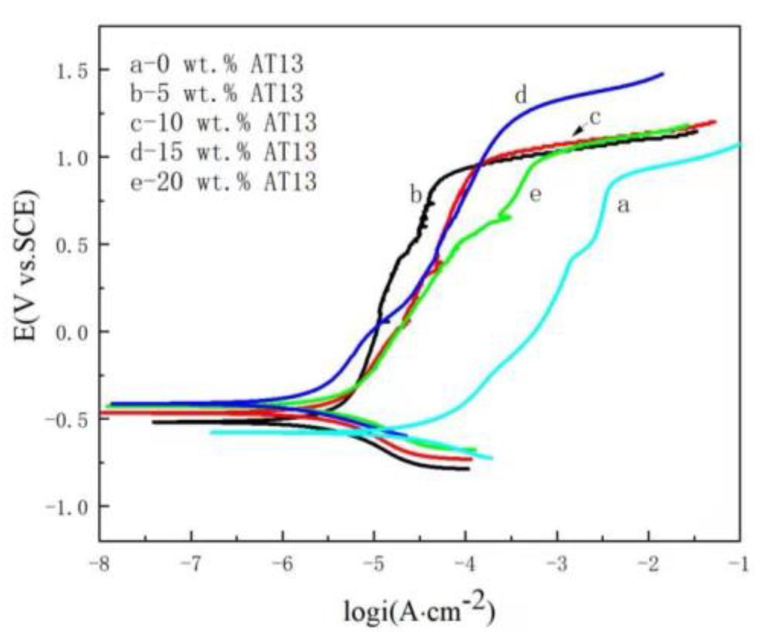
| Content of AT13/wt.% | Ecorr/mV | icorr/A cm−2 | ipass/A cm−2 | Etr/mV | Corrosion Rate/mpy |
|---|---|---|---|---|---|
| 0 | −580 | 5.14 × 10⁻⁵ | 5.42 × 10⁻³ | 867 | 25.06 |
| 5 | −519 | 7.50 × 10⁻⁶ | 6.23 × 10⁻⁵ | 905 | 6.47 |
| 10 | −467 | 5.01 × 10⁻⁶ | 1.12 × 10⁻⁴ | 993 | 5.49 |
| 15 | −411 | 1.75 × 10⁻⁶ | 5.37 × 10⁻⁴ | 1236 | 2.07 |
| 20 | −430 | 4.06 × 10⁻⁶ | 6.94 × 10⁻⁴ | 1012 | 4.60 |
| Time (day) | Rs (Ω·cm−2) | Rct (Ω·cm−2) | CPEdl | Rf (Ω·cm−2) | CPEf | Goodness of Fit |
|---|---|---|---|---|---|---|
| 0 | 4.56 | 950.1 | 8.58 × 10⁻⁴ | / | / | 2.20 × 10⁻³ |
| 1 | 5.036 | 402.1 | 2.07 × 10⁻³ | / | / | 1.13 × 10⁻³ |
| 4 | 3.845 | 838.3 | 5.05 × 10⁻⁴ | / | / | 1.08 × 10⁻³ |
| 10 | 5.026 | 680.4 | 7.94 × 10⁻⁴ | / | / | 1.09 × 10⁻³ |
| 17 | 4.992 | 177.1 | 8.80 × 10⁻³ | 588.7 | 3.14 × 10⁻³ | 3.19 × 10⁻⁴ |
| 24 | 4.492 | 133.4 | 4.23 × 10⁻⁴ | 489.8 | 1.46 × 10⁻³ | 4.04 × 10⁻⁵ |
| 31 | 2.781 | 101.6 | 1.2 × 10⁻¹ | 274.8 | 2.04 × 10⁻³ | 6.47 × 10⁻⁴ |
Publisher’s Note: MDPI stays neutral with regard to jurisdictional claims in published maps and institutional affiliations. |
© 2022 by the authors. Licensee MDPI, Basel, Switzerland. This article is an open access article distributed under the terms and conditions of the Creative Commons Attribution (CC BY) license (https://creativecommons.org/licenses/by/4.0/).
Share and Cite
Chu, Z.; Shi, H.; Xu, F.; Xu, J.; Zheng, X.; Wang, F.; Zhang, Z.; Hu, Q. Study of the Corrosion Mechanism of Iron-Based Amorphous Composite Coating with Alumina in Sulfate-Reducing Bacteria Solution. Coatings 2022, 12, 1763. https://doi.org/10.3390/coatings12111763
Chu Z, Shi H, Xu F, Xu J, Zheng X, Wang F, Zhang Z, Hu Q. Study of the Corrosion Mechanism of Iron-Based Amorphous Composite Coating with Alumina in Sulfate-Reducing Bacteria Solution. Coatings. 2022; 12(11):1763. https://doi.org/10.3390/coatings12111763
Chicago/Turabian StyleChu, Zhenhua, Haonan Shi, Fa Xu, Jingxiang Xu, Xingwei Zheng, Fang Wang, Zheng Zhang, and Qingsong Hu. 2022. "Study of the Corrosion Mechanism of Iron-Based Amorphous Composite Coating with Alumina in Sulfate-Reducing Bacteria Solution" Coatings 12, no. 11: 1763. https://doi.org/10.3390/coatings12111763