1. Introduction
The surface wrinkling phenomenon is ubiquitous in nature and our daily life on the scale of nanometers to kilometers, such as cell surfaces, water-swelled fingertips, brain cortex, mucosa of digestive tract, and mountains [
1,
2]. Generally, surface wrinkling occurs in a system consisting of a rigid thin film and a soft thick substrate (i.e., a film/substrate system). When the system is subjected to certain compression stress caused by pre-stretch-release [
3,
4,
5,
6,
7,
8,
9,
10], solvent/thermal-induced deformation [
11,
12,
13,
14,
15], or photo-induced molecular chain orientation [
16], surface wrinkling will spontaneously occur to minimize the energy of the system [
2,
17,
18]. Recently, surface wrinkling has aroused tremendous research interests in surface science and engineering. Considerable efforts have been made to harness wrinkle patterns for broad applications, including stretchable electronics [
2,
19,
20,
21,
22,
23], smart windows/displays [
3,
5], tunable surface wetting/friction [
24,
25,
26], soft actuators [
27,
28], and information encoding [
13,
14,
16].
Surface wrinkling has been widely employed in constructing stretchable electronics (e.g., strain sensors [
20,
21,
22], pressure sensors [
8,
29], stretchable electrodes [
7,
15,
30], and energy harvesters [
4,
10]) and plays a significant role in enhancing the performances of these devices. Most existing studies have been devoted to integrating hard inorganic conductive nanoparticles (e.g., carbon nanotubes (CNTs), reduced graphene oxide (RGO)) onto soft substrates (e.g., polydimethylsiloxane (PDMS), thermoplastic polyurethane (TPU)) in wrinkling configurations. Recent progress shows that the wrinkle structure exhibits appealing capability in accommodating the large applied tensile deformations which endows the functional devices with notable stretchability [
7,
15,
20,
21,
22,
30].
Existing methods for the construction of conductive wrinkle surfaces mostly rely on the prestretch–release method, i.e., coating conductive active thin layers on prestretched elastomers by spraying [
19,
30], spin coating [
7], blade coating [
10], sputtering [
31], drop casting [
8,
32], layer transferring [
6,
21], and so forth, then releasing the prestrain to induce surface wrinkling. Although it is an easy-to-use and low-cost method to create a tunable conductive wrinkled surface layer, there still exists some obvious limitations. Normally, a stretching–releasing equipment is essential to perform the wrinkling process. Therefore, the sample size is limited to a centimeter scale and this method is not applicable for samples with arbitrary shapes (e.g., curved structures). The other methods, e.g., swelling-induced wrinkling [
11,
15] or thermal-induced wrinkling methods [
13,
14], usually require several procedures to construct the wrinkle surfaces, i.e., typically the independent layer deposition procedure and swelling/heating procedure. Obviously, the existing methods are complicated and time consuming. Furthermore, the aforementioned coating methods usually face the shortcoming of weak interfacial interaction between the conductive layer and the substrate. For instance, when the wrinkled surface layer suffers from long-term cyclic stretching–releasing or the large, applied strain exceeds the stored prestrain, undesired cracks and delamination will occur [
5,
10,
15,
23,
33,
34,
35]. Recently, ultrasonication has been well employed to accelerate the deposition of various nanoparticles (e.g., CNTs, graphite nanoplatelets) onto the thermoplastic elastomer surface (e.g., TPU electrospun nanofiber mats) [
36,
37,
38,
39]. With the assistance of the driving forces of ultrasonication, nanoparticles with very high speed and energy drastically impact the polymer substrate surface, resulting in interfacial collision and sintering between nanoparticles and the substrate surface. Notably, the nanoparticles can be embedded into the substrate surface, leading to a strong interfacial interaction. However, since the aforementioned nanomodification is normally performed in the non-swelling water dispersions, there is no compression stress between the surface layer and polymer substrate. Thus, no wrinkle structure would be induced in the ultrasonication process. Therefore, developing a one-pot, rapid, and cost-effective method to create robust conductive wrinkled layers on elastomers (irrespective of planar or curved substrate surfaces) is urgently needed.
Herein, an ultrasonic-assisted deposition strategy is developed to rapidly create a labyrinth wrinkled surface layer on PDMS fiber. The conductive one-dimensional (1D) CNTs, two-dimensional (2D) RGO, or non-conductive zero-dimensional (0D) SiO2 nanoparticles are successfully anchored on the PDMS fiber surfaces which are assembled into micro-scale wrinkle patterns. The swelling of the substrate induced by the good solvent in the dispersion as well as the ultrasonic treatment play crucial roles in the surface layer deposition and wrinkling. The ultrasonic-assisted deposition method is applicable to arbitrarily shaped PDMS surfaces, such as fiber, sheet, and porous sponge, and superior to the typical prestretch–release method. It is an efficient, energy-saving, and universal surface wrinkling method for the nanomodification of various functional nanoparticles on PDMS surfaces with robust interfacial strength, which is superior to the existing surface wrinkling strategies. As a demonstration, the wrinkled conductive CNTs@PDMS fiber is adopted as a strain sensor with significant stretchability (ca. 300%). The strain sensor shows tunable strain-sensing performance and can be well applied in human motion detection, voice recognition, and air-flow monitoring.
2. Materials and Methods
2.1. Materials
The PDMS prepolymer and curing agent (Sylgard 184) were purchased from Dow Corning Corporation (Midland, TX, USA. CNTs (diameter of 5~15 nm, length of 10~30 μm) and RGO (thickness of 0.55~3.74 nm, size of 0.5~3 μm) were purchased from Times Nano (Chengdu Organic Chemicals Co., Ltd., Chengdu, China). SiO2 nanoparticles (AEROSIL A200, Evonik Industries AG, Frankfurt, Germany) with a diameter of 12 nm were obtained from the local market. Cyclohexane, ethanol, and citric acid monohydrate (CAM) were supplied by Aladdin Chemical Reagent Co., Ltd. (Shanghai, China). All chemicals were analytical grade and used without further purification.
2.2. Preparation of PDMS Substrates
First, PDMS prepolymer and curing agent, with the weight ratio of 10:1, were mixed homogeneously, followed by degassing to obtain a precursor solution of PDMS. Subsequently, the PDMS precursor was injected into a polytetrafluoroethylene (PTFE) tube (inner diameter of ca. 600 μm) or cast onto a PTFE substrate and heated at 80 °C for 3 h. After demolding, the PDMS fiber and sheet were obtained, respectively. As for the preparation of porous PDMS sponge, the PDMS precursor (10:1), and CAM with the weight ratio of 1:6 were mixed homogeneously. After being degassed for 30 min, the mixture was poured into a PTFE box and cured at 80 °C for 3 h. Subsequently, the sample was immersed into an ethanol bath for 6 h to remove CAM. Finally, the obtained porous PDMS sponge was dried by oven for further use.
2.3. Ultrasonic-Assisted Deposition of Wrinkled Layers on PDMS Surfaces
Typically, 25 mg CNTs, 25 mg RGO, or 50 mg SiO2 nanoparticles were separately dispersed into 50 mL cyclohexane and treated using an ultrasonic probe (Scientz-IID, 20 kHz, 400 W, Ningbo Xinzhi Biotechnology Co., Ltd., Ningbo, China) for 2 h to obtain 0.5 mg/mL CNT/cyclohexane dispersion, 0.5 mg/mL RGO/cyclohexane dispersion, 1 mg/mL SiO2/cyclohexane dispersion, respectively. The PDMS fiber, sheet, and porous sponge were ultrasonically treated in any as-prepared dispersions for a designed time to deposit CNTs, RGO, or SiO2 onto the surface of PDMS substrates, respectively. Then, the samples were washed thoroughly with deionized water to remove the unanchored nanoparticles. For comparison, a part of PDMS fibers were dipped into a 1 mg/mL CNT/ethanol dispersion for several cycles to fabricate CNTs@PDMS fibers.
2.4. Preparation of CNTs@PDMS Fiber Strain Sensor
The CNTs@PDMS fiber prepared from ultrasonic treatment for different times were employed to assemble the strain sensors. Copper-tape electrodes were attached on two sides of the CNTs@PDMS fiber by silver paste. Then, the electrodes were encapsulated by PDMS (10:1) to improve the stability against strains. The distance between the two electrodes was 15 mm.
2.5. Characterization
The morphological characterization was conducted by scanning electron microscopy (SEM, Hitachi, S-4800, Hitachi Manufacturing Co., Ltd., Tokyo, Japan). The accelerating voltage and the working distance were 5 kV and 15 mm, respectively. Optical photographs were observed by using a stereo microscope (Nikon, SH-200, Nikon Co., Ltd., Tokyo, Japan). The volume electrical conductivity of the conductive fibers was measured by the two-point method. Specifically, silver paint was coated on the surfaces of both ends of the fibers and the resistance of the fibers was tested by a sourcemeter (Keithley 2400, Tektronix Technology Co., Ltd., Beaverton, OR, USA) at a DC voltage of 0.1 V. The conductivity (σ) of the fiber was calculated by the equation: σ = L/RS, where L, R, and S represent length of the fiber, resistance of the fiber, and cross-section area of the fiber, respectively. For a certain fiber, more than five samples were tested to estimate the conductivity and to calculate the corresponding standard deviation. The strain-sensing behaviors of CNTs@PDMS fiber strain sensors were analyzed on a motorized translation stage (Thorlabs, LTS150, Thorlabs Inc, Newtown, CT, USA) coupled with the sourcemeter. For the stability test, the CNTs@PDMS fibers with similar conductivity prepared from the ultrasonic-assisted deposition method or dip-coating method were separately immersed into water with ultrasonic washing (Ultrasonic cleaner, KQ300DE, 300 W, Kunshan ultrasonic instrument Co., Ltd., Kunshan, China) for 5 min. The conductivity before and after the ultrasonic cleaning process was measured by the sourcemeter, respectively.
3. Results and Discussion
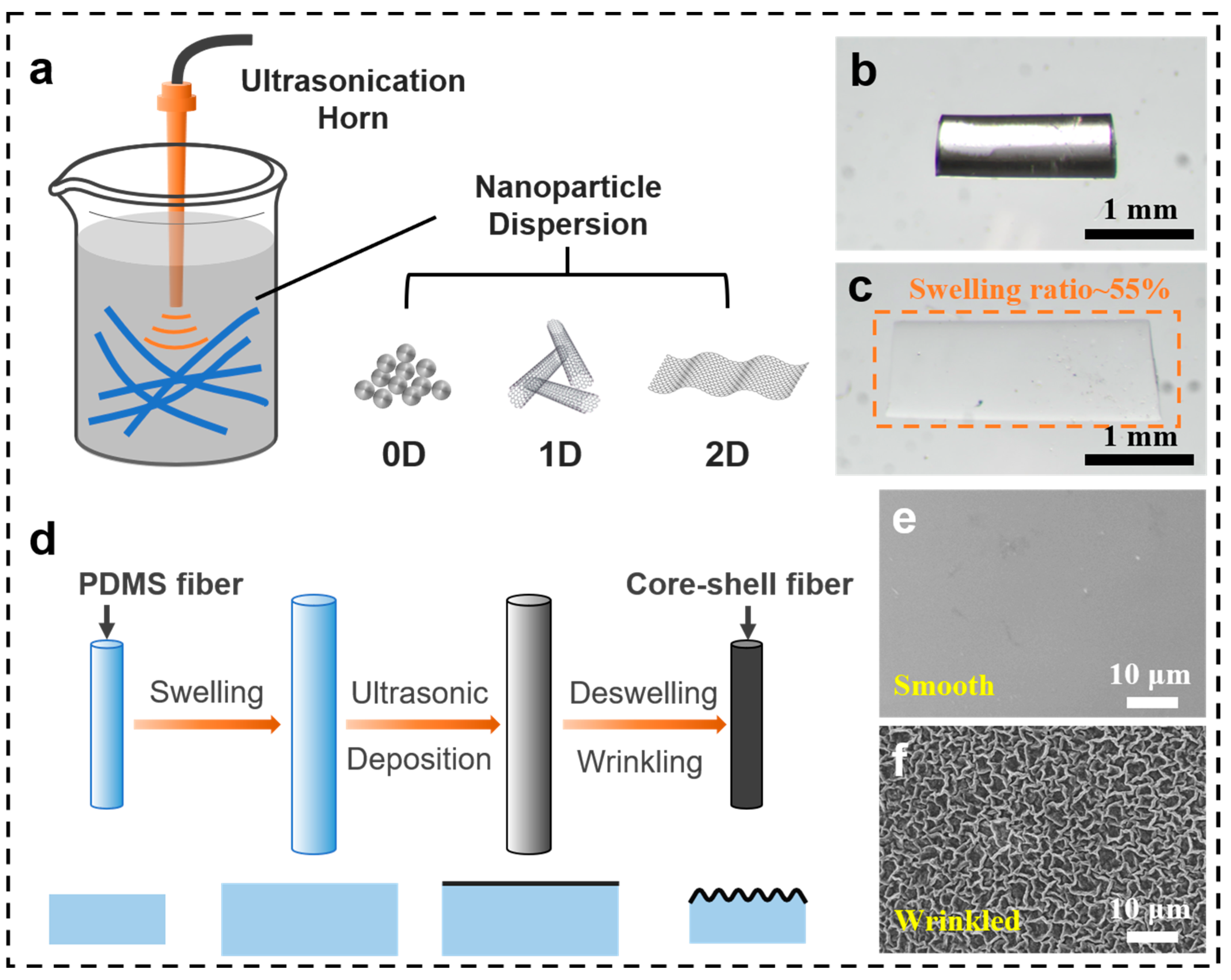
Figure 1 is a schematic illustration for the ultrasonic-assisted deposition method to decorate the wrinkled nanoparticle thin layer onto the surface of PDMS substrates. First, the PDMS substrates (e.g., fibers, sheets, or porous sponges) were soaked into a nanoparticle dispersion composed of either 0D, 1D, or 2D nanoparticles (e.g., SiO
2, CNTs, RGO) and cyclohexane. Under the ultrasonic treatment, the PDMS substrates were immediately swelled by cyclohexane within 5 s. For instance, the length and diameter of the PDMS fiber expand at a ratio of ca. 55%, indicating an isotropic swelling, as shown in
Figure 1b,c. With further ultrasonic treatment, the nanoparticles were uniformly deposited onto the surface of the swollen PDMS fiber. After a designed ultrasonic treatment time, the PDMS fiber was taken out of the dispersion. Subsequently, a wrinkle structure was spontaneously formed on the surface of the PDMS fiber upon the solvent evaporation. The surface wrinkling mechanism is demonstrated in
Figure 1d. Obviously, this swelling–ultrasonic treatment is a one-pot procedure to create a wrinkled surface layer onto PDMS substrates. It is also a facile and efficient method without using prestretch–release equipment. For instance, after ultrasonic treatment in a CNT/cyclohexane dispersion for only 5 min, a labyrinth wrinkled CNT surface layer was formed on the PDMS fiber, in sharp contrast to the initial smooth PDMS fiber (
Figure 1e,f).
In our case, solvent swelling–deswelling is adopted to induce surface wrinkling between the surface nanoparticle layer and polymer substrate. PDMS elastomer with outstanding solvent resistance is chosen as the polymer substrate. Due to the chemically crosslinked polymer chains of thermosetting elastomer, PDMS substrate will be only swelled rather than dissolved in cyclohexane even with violent ultrasonic treatment. The voids among the PDMS molecular chains caused by solvent swelling enable the nanoparticles to anchor on the PDMS surface. Oppositely, thermoplastic polymer (e.g., TPU nanofiber mats) will be easily dissolved in its good organic solvent under ultrasonication.
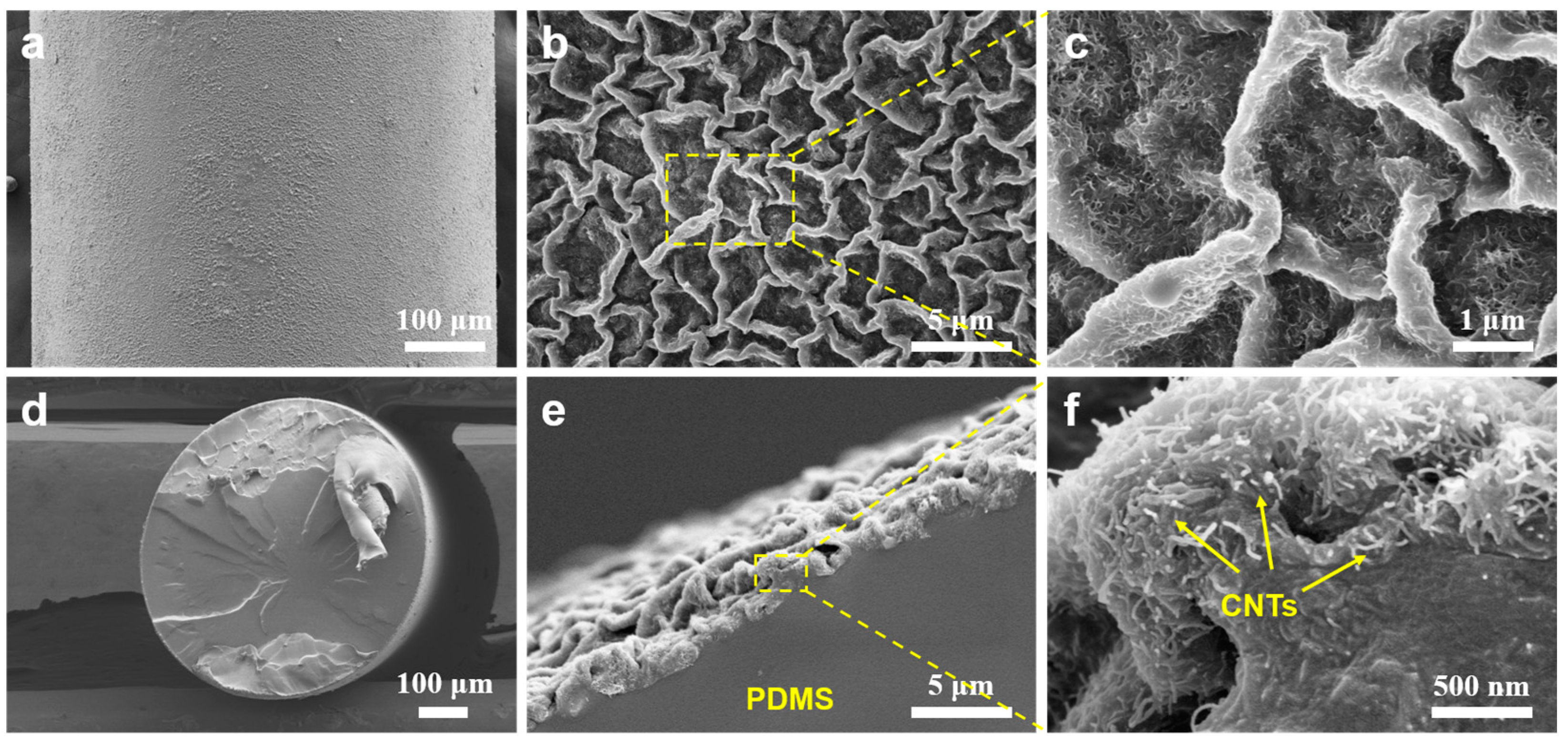
Figure 2 presents the surface and cross-section SEM images of CNTs@PDMS fibers. After being subjected to ultrasonic treatment for 5 min, the CNTs are thoroughly and uniformly decorated on the PDMS fiber surface, as shown in
Figure 2a–c. During the decoration process, ultrasonication not only provides the driving force for CNTs to anchor on the PDMS surface, but also prevents CNTs from undesired agglomeration. Interestingly, a labyrinth wrinkle structure is formed on the surface of the PDMS fiber (
Figure 1b,c), which is significantly distinct from the oriented wrinkle patterns induced by the uniaxial prestretch–release method [
6,
9,
10]. This can be ascribed to the isotropic volume expansion of the PDMS fiber during solvent swelling (
Figure 1b,c), which will generate isotropic compression stress between the deposited CNTs layer and PDMS substrate after solvent evaporation. Therefore, the labyrinth wrinkle pattern is induced, which is very similar to that induced by the biaxial prestretch–release method [
7,
18]. Obviously, both swelling and ultrasonication play crucial roles in the formation of the wrinkled surface layer on PDMS substrates, as demonstrated in
Figure 1d.
From the cross-section view of the CNTs@PDMS fiber (
Figure 2e,f), it is extremely difficult to distinguish the interface between the CNT skin layer and the PDMS matrix because the very thin CNT film (nanometer scale) is firmly bonded on the PDMS fiber surface. The enlarged SEM image (
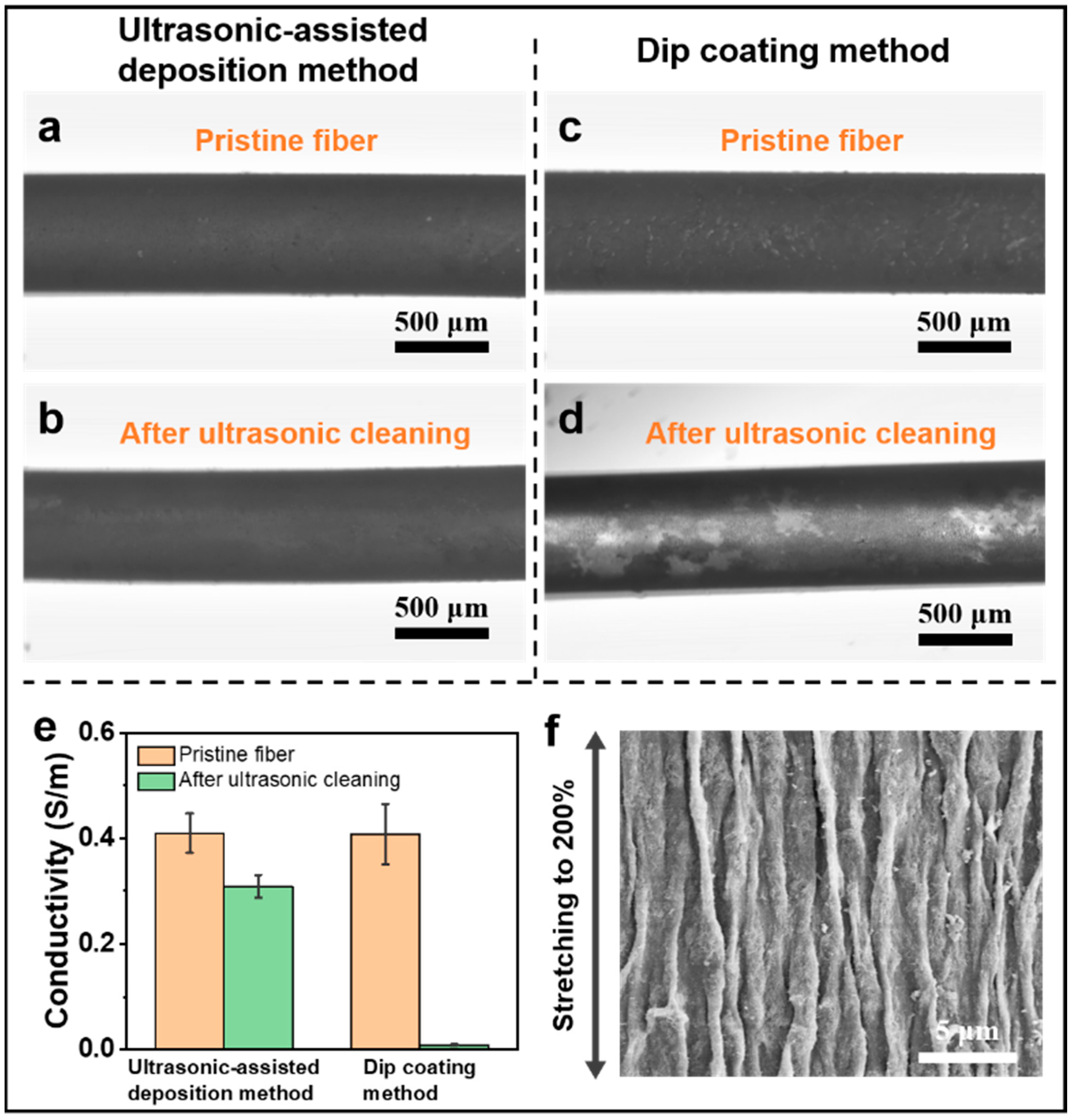
Figure 2f) demonstrates that CNTs are partially embedded into the PDMS surface rather than just absorbed on the surface, which could provide strong interfacial interaction and prevent the CNT layer from cracking or delaminating upon large strain applied. To characterize the robustness of the wrinkled layer fabricated by the ultrasonic-assisted deposition method, the as-prepared CNTs@PDMS fibers are soaked in water for ultrasonic cleaning (
Figure 3a,b). The conductivity of the CNTs@PDMS fiber slightly decreases from 0.41 S/m to 0.31 S/m (
Figure 3e) and the fiber surface layer shows no obvious change after ultrasonic cleaning (
Figure 3a,b). Furthermore, the wrinkled CNT surface layer can withstand 200% tensile strain without obvious cracking and delaminating (
Figure 3f). On the contrary, the CNTs@PDMS fiber with similar initial conductivity fabricated by the dip-coating method demonstrates poor stability. Apparent delaminating is observed in
Figure 3c,d and, thus, the conductivity of the fiber sharply decreases to 0.008 S/m (
Figure 3e). Hence, the proposed ultrasonic-assisted deposition method provides a worthwhile strategy to deposit the robust wrinkled surface layer with strong interfacial bonding strength.
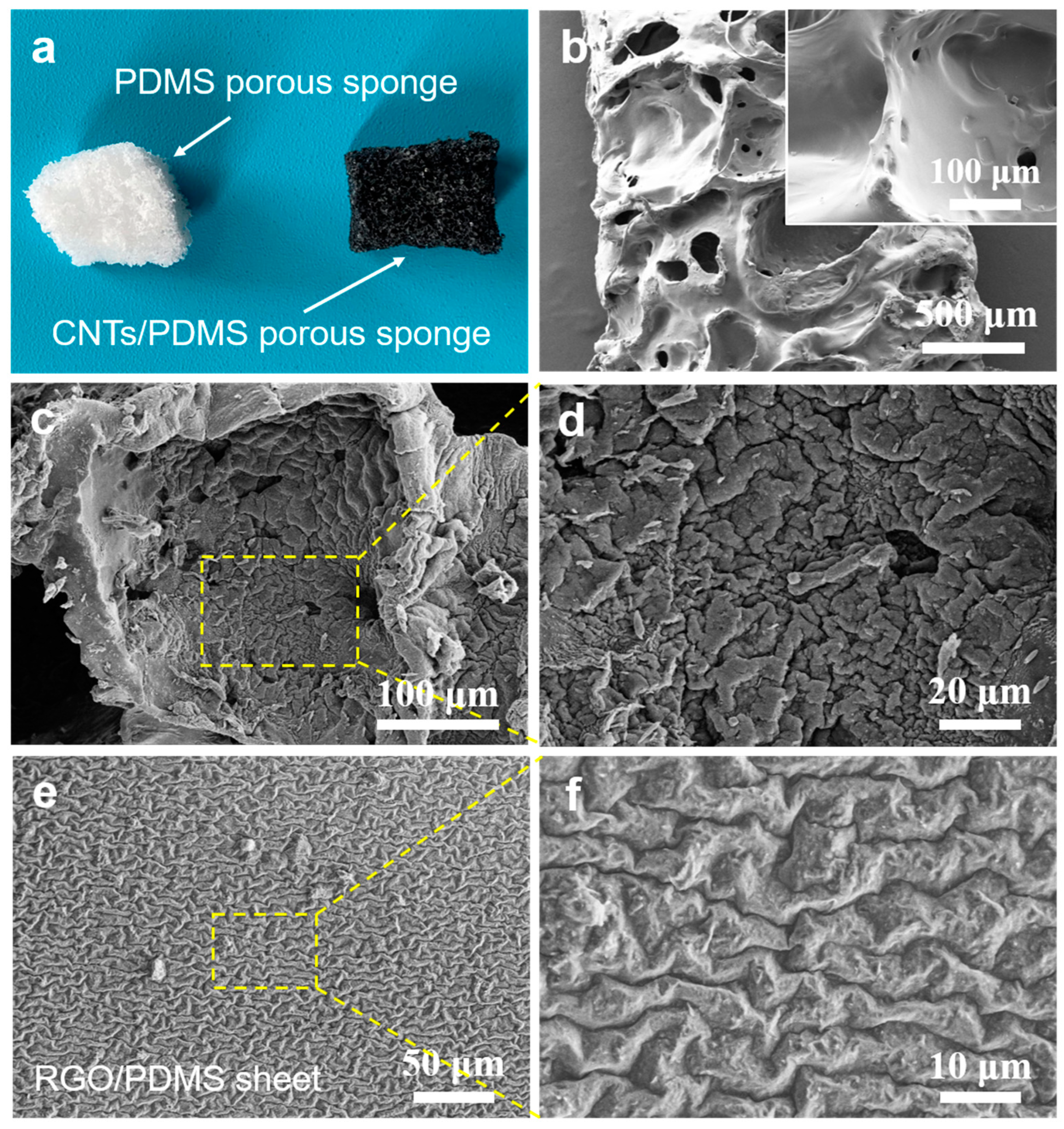
Normally, the prestretch–release method is not applicable to create a labyrinth wrinkle structure on curved surfaces, especially the curved surface of microfiber, since the biaxial stretching is hard to be performed for the microfiber. By contrast, the proposed ultrasonic-assisted deposition method can not only create a wrinkle pattern on the curved surface of the fiber, but also the complex curved surface of the porous PDMS sponge. As shown in
Figure 4a, the pristine white-colored porous PDMS sponge becomes black after ultrasonic-assisted deposition of CNTs for 15 min. The surface morphologies indicate that the wrinkled CNTs layer is successfully decorated on the surface of the porous sponge (
Figure 4b–d). Additionally, a labyrinth wrinkled RGO layer is easily formed on the planar surface of the PDMS sheet after the PDMS sheet is ultrasonically treated in a RGO/cyclohexane dispersion (
Figure 4e,f). It can be concluded that when the PDMS substrates are subjected to ultrasonic treatment in the liquid-phase condition, the nanoparticles can be uniformly anchored on the arbitrary shape PDMS substrate, irrespective of the planar or curved surface.
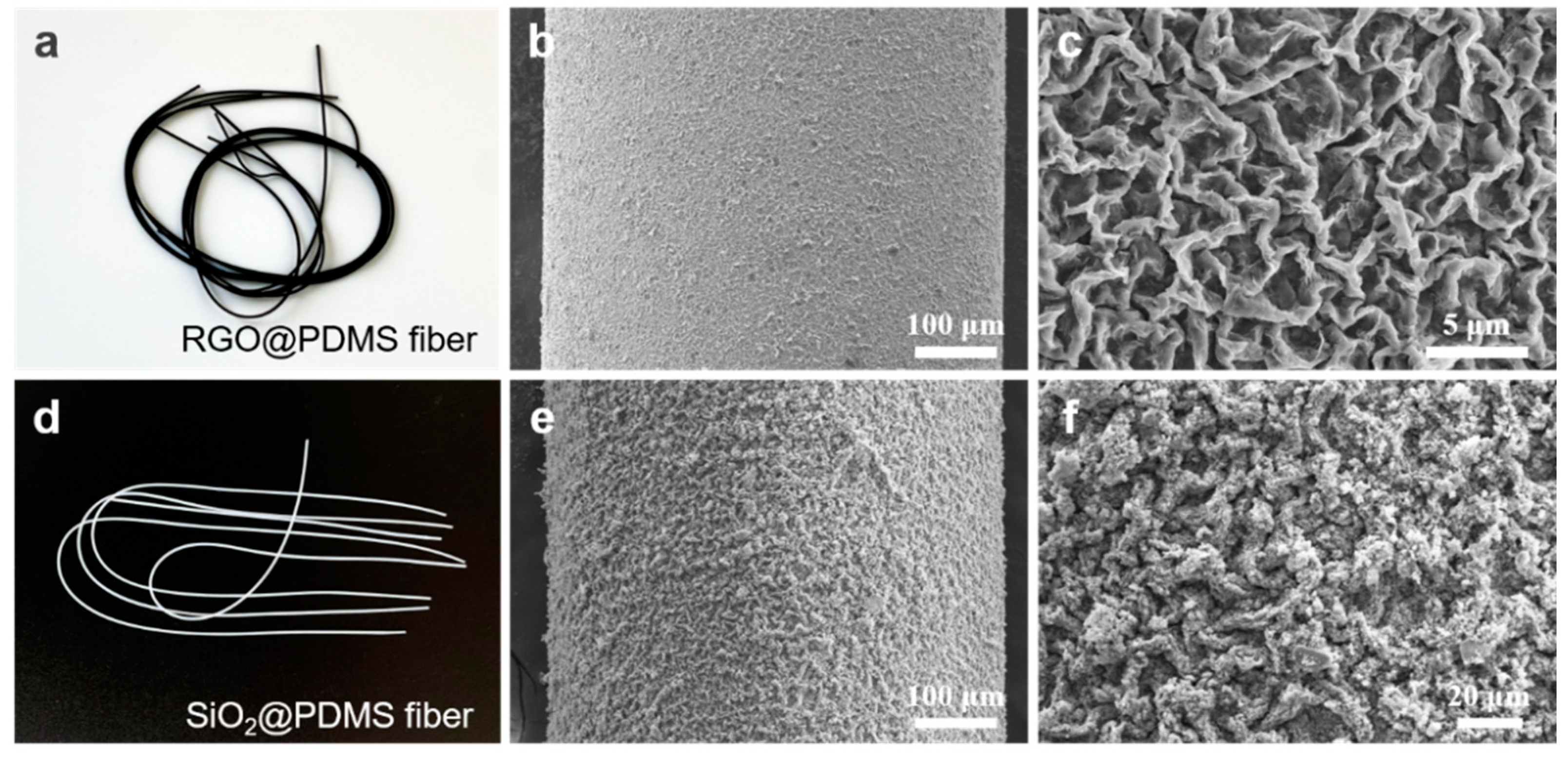
The ultrasonic-assisted deposition method provides a facile and universal route to achieve the surface nanomodification of the PDMS substrate. When the PDMS fibers are ultrasonically treated in 0.5 mg/mL RGO/cyclohexane for 5 min, the transparent PDMS fibers turn black, as shown in
Figure 5a. As a result, the 2D RGO is uniformly anchored on the PDMS fiber surface forming a labyrinth wrinkle structure (
Figure 5b,c). The conductivity of the as-prepared RGO@PDMS fiber is 0.09 ± 0.005 S/m. Similarly, the nonconductive 0D SiO
2 nanoparticles can be also successfully anchored on the PDMS fibers with wrinkle patterns (
Figure 5d–f). Therefore, the proposed ultrasonic-assisted deposition method is a universal strategy to create a labyrinth wrinkled surface layer compositing various nanoparticles on the PDMS surface. It is also highly expected that the proposed method would be applicable to more varieties of functional nanoparticles (e.g., carbon black, graphene quantum dots, Ag nanoparticles) for wide application prospects.
Based on the surface and cross-section SEM images in
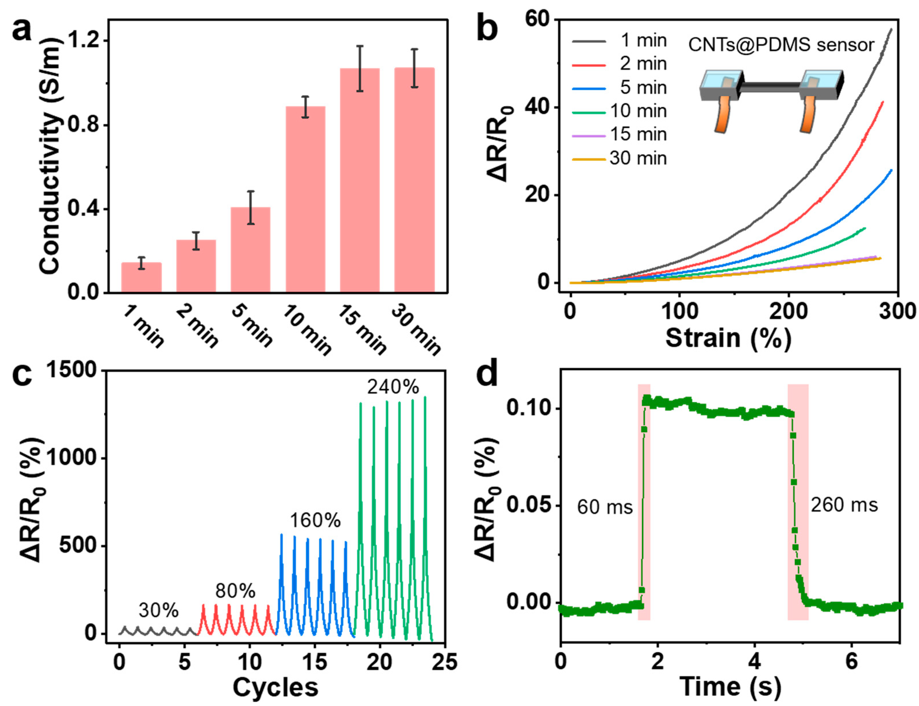
Figure 2, the CNTs in the skin layer of the PDMS fiber form a well-conductive network. Additionally, the electrical conductivity of the core-shell CNTs@PDMS fiber can be easily tuned by the ultrasonic time. As demonstrated in
Figure 6a, after ultrasonically treated for only 1 min, the insulating PDMS fiber becomes conductive (0.14 S/m). Then, the conductivity of the CNTs@PDMS fiber gradually increases with the ultrasonic treatment time from 2 min to 15 min. These results can be attributed to the fact that the anchored CNT amount increases with prolonged ultrasonic time. As the ultrasonic treatment time further increases to 30 min, the conductivity of the CNTs@PDMS fiber (1.07 S/m) shows no significant change compared with that of the corresponding fiber prepared from the ultrasonic treatment of 15 min. Furthermore, the conductivity of the CNTs@PDMS fiber can also be modulated by the concentration of the dispersion. For instance, the conductivity of the CNTs@PDMS fibers prepared from the ultrasonic treatment of 5 min in a 1 mg/mL CNT/cyclohexane dispersion is 0.91 ± 0.04 S/m, which is more than twice that of the corresponding CNTs@PDMS fiber prepared from the ultrasonic treatment of 5 min in a 0.5 mg/mL CNT/cyclohexane dispersion (0.40 ± 0.08 S/m,
Figure 6a). This can be ascribed to the following reason: with the increase in the concentration, there is a higher probability for CNTs to impact the PDMS surface under ultrasonication. Thus, the anchored amount of CNTs significantly increases, resulting in the promotion of the conductivity.
The conductive CNTs@PDMS fibers prepared from different ultrasonic treatment times are assembled into stretchable strain sensors and the corresponding strain-sensing performances are demonstrated in
Figure 6b. The relative resistance change, defined as the ratio of the change in resistance (Δ
R) to the initial resistance (
R0), is calculated to evaluate the response behavior of the fiber strain sensors. When the fiber strain sensor suffers from tensile strain, the tangled CNTs would slip to reduce the number of contact sites, thus causing the increase in the resistance. It can be clearly observed that all the fiber strain sensors present remarkable stretchability (ca. 300%). All the fiber sensors can keep the conductive paths connected before the fibers are stretched to break, indicating that the wrinkled CNT conductive networks are strong enough to resist the large strain. Upon stretching, the wrinkled CNT layer could release the restored prestrain to accommodate the applied strain, prominently enhancing the stretchability of the strain sensor. Obviously, the strain-sensing behavior is closely related to the initial conductivity of the CNTs@PDMS fiber strain sensor. At a fixed applied strain (e.g., 250%), the value of
ΔR/R0 decreases with the increase in initial conductivity of the CNTs@PDMS fiber strain sensor, indicating the declining sensitivity. Considering the fact that the higher initial conductivity of the CNTs@PDMS fiber strain sensor, the more robust conductive network would be formed, the conductive networks are less affected compared with the ones with lower initial conductivity.
For further demonstration of the strain-sensing performances, the CNTs@PDMS fiber strain sensor prepared from ultrasonic treatment of 5 min is chosen for detailed testing.
Figure 6c shows the cyclic strain-sensing behaviors of the fiber strain sensor under different applied strains. The fiber strain sensor demonstrates outstanding stability under multicycle strain loadings, irrespective of the strain applied. The cyclic stability could be ascribed to the strong interfacial interaction between the wrinkled conductive CNT skin layer and PDMS fiber, which could guarantee the reversible deformation of the conductive networks upon stretching–releasing. Furthermore, the fiber strain sensor exhibits very rapid response and recovery rates. As shown in
Figure 6d, the response time and recovery time are 60 ms and 260 ms, respectively.
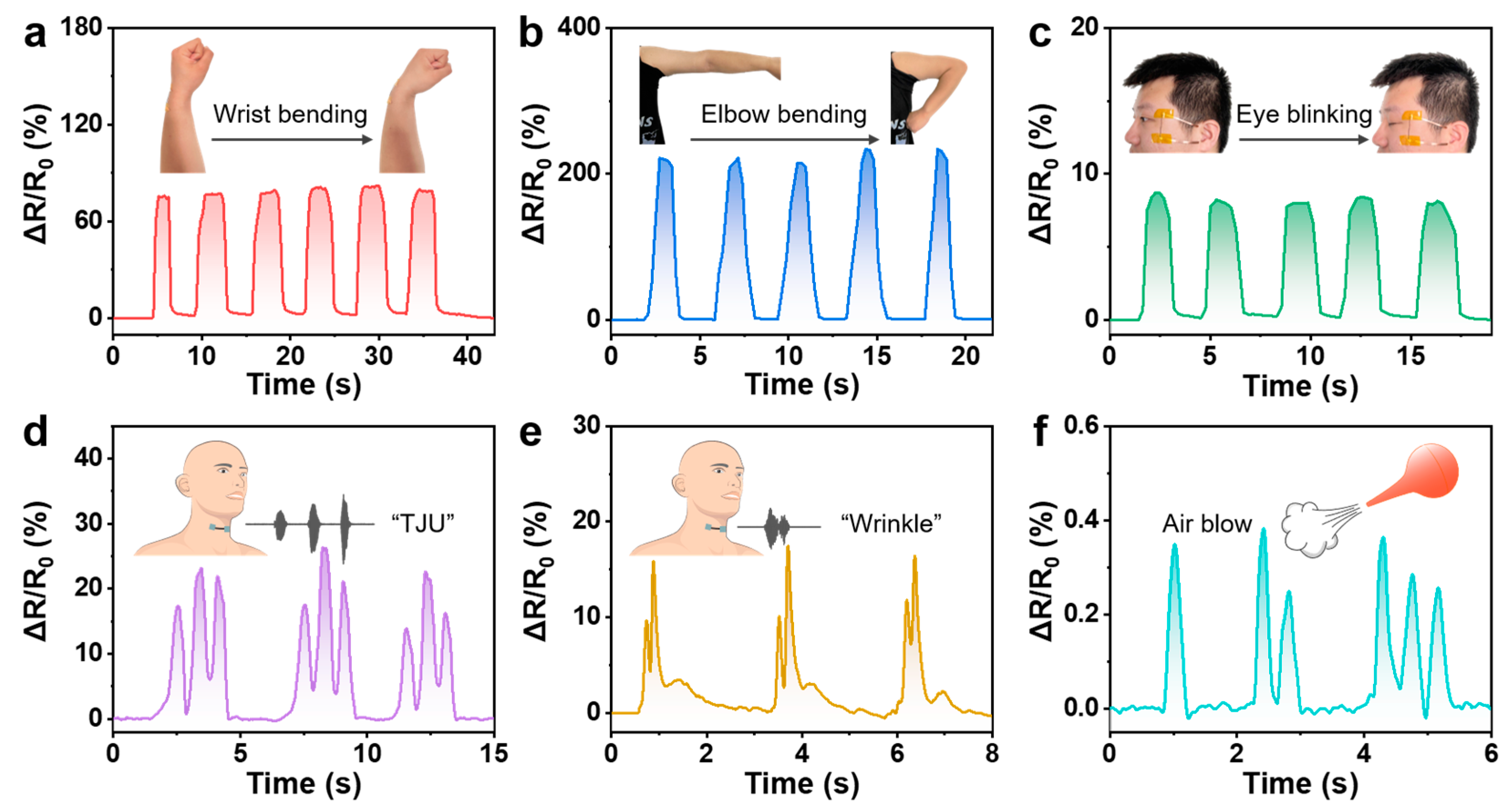
Taking advantages of the good strain-sensing behaviors of the CNTs@PDMS fiber strain sensor, the strain sensor can be applied to monitoring various human motions at different strain scales. As shown in
Figure 7a–c, the fiber strain sensors are attached onto the wrist, elbow, and canthus of the volunteer to monitor the motions of these parts in real-time, respectively. The signal response of the fiber strain sensors increases significantly when they are subjected to wrist bending and elbow bending, indicating the large tensile strains are induced by the bending motions. With respect to the relative weak blinking movement, it can be well captured by the sensitive strain sensor as well. The fiber strain sensor exhibits stable and repeatable response signals which is beneficial to wearable human motion detection. More attractively, it has the capability to identify the complex skin stretching the over human throat upon speaking “TJU” and “Wrinkle”, respectively (
Figure 7d,e). For the three-syllable word “TJU”, three individual peaks with different intensity appear (
Figure 7d). By contrast, the word “Wrinkle”, with two consecutive syllables, induces two major signal peaks (
Figure 7e). The excellent voice recognition capability enables the fiber strain sensor to have great potential in wearable intelligent voice control system and phonation rehabilitation exercises. The fiber strain sensor can even capture the extremely weak strain caused by the air flow. As shown in
Figure 7f, the frequency and the intensity of the air flow generated from a rubber suction bulb can be accurately identified. Therefore, the fiber stain sensor has excellent strain-sensing performances, irrespective of the strain level.


