
Contribution to the Research and Development of Innovative Building Components with Embedded Energy-Active Elements


Abstract
:1. Introduction
- (1)
- Analysis and synthesis of knowledge in the field of active thermal protection and thermal barrier (Section 2);
- (2)
- Description of the basic calculation equations for thermal barrier sizing (Section 3.1);
- (3)
- Analysis of the ISOMAX panel composition and the development of a mathematical–physical model (Section 3.2);
- (4)
- Analysis of the composition of the innovative envelope panel solution and development of the mathematical–physical model, (Section 3.3);
- (5)
- Development and design of innovative panels and the details of panel joining (Section 3.4);
- (6)
- Inductive and analog forms of formation of the innovative panel with integrated energy-active elements (Section 4.1);
- (7)
- Analysis of the energy potential of the retrofitted panel with a thermal barrier compared to the original panel (Section 4.2);
- (8)
- Synthesis of the knowledge obtained from the scientific analysis and the transformation of the data into the design and implementation of the IDA I prefabricated house prototype (Section 4.3).
2. Overview of Studies Dealing with Active Thermal Protection and Thermal Barrier
3. Innovated Thermal Barrier Panel Compared to the Patented ISOMAX Panel
3.1. Initial Calculation Relations for Thermal Barrier Dimensioning
- Ri is the thermal resistance of the jth layer of the structure ((m2·K)/W),
- dj is the thickness of the jth layer of the structure (m), and
- Rj is the thermal resistance of the jth layer of the structure ((m2·K)/W),
- Rc is the total thermal resistance of the structure ((m2·K)/W),
- Rsi is the thermal resistance to heat transfer at the internal surface of the structure ((m2·K)/W),
- Rse is the thermal resistance to heat transfer at the external surface of the structure ((m2·K)/W), and
- R is the thermal resistance of the structure ((m2·K)/W), [23].
- U is the heat transfer coefficient of the structure ((m2·K)/W),
- Rsi is the thermal resistance to heat transfer at the internal surface of the structure ((m2·K)/W),
- R is the thermal resistance of the structure ((m2·K)/W), and
- Rse is the thermal resistance to heat transfer at the external surface of the structure ((m2·K)/W), [23].
- θj is the temperature in the jth layer of the structure (°C),
- θi is the internal design temperature (°C),
- θe is the outdoor design temperature in winter (°C),
- U is the heat transfer coefficient of the structure ((m2·K)/W),
- Rsi is the thermal resistance to heat transfer at the internal surface of the structure ((m2·K)/W), and
- Cp is the specific heat under constant pressure (kJ/kg K),
- p is the density of the wall layer material (kJ/m3)],
- T is the temperature (°C), and
- t is the time (s) [24].
- λ is the thermal conductivity (W/m K),
- hi is the convective/radiative heat transfer coefficient on the internal surface (W/m2·K),
- TFi(t) is the internal surface temperature (°C), and
- Ti is the internal air temperature (°C) [24].
- he(t) is the convective heat transfer coefficient on the external surface (W/m2·K),
- Te(t) is the solar temperature (°C), and
- q(t) is the heat flux normal to the surface (W/m2), and
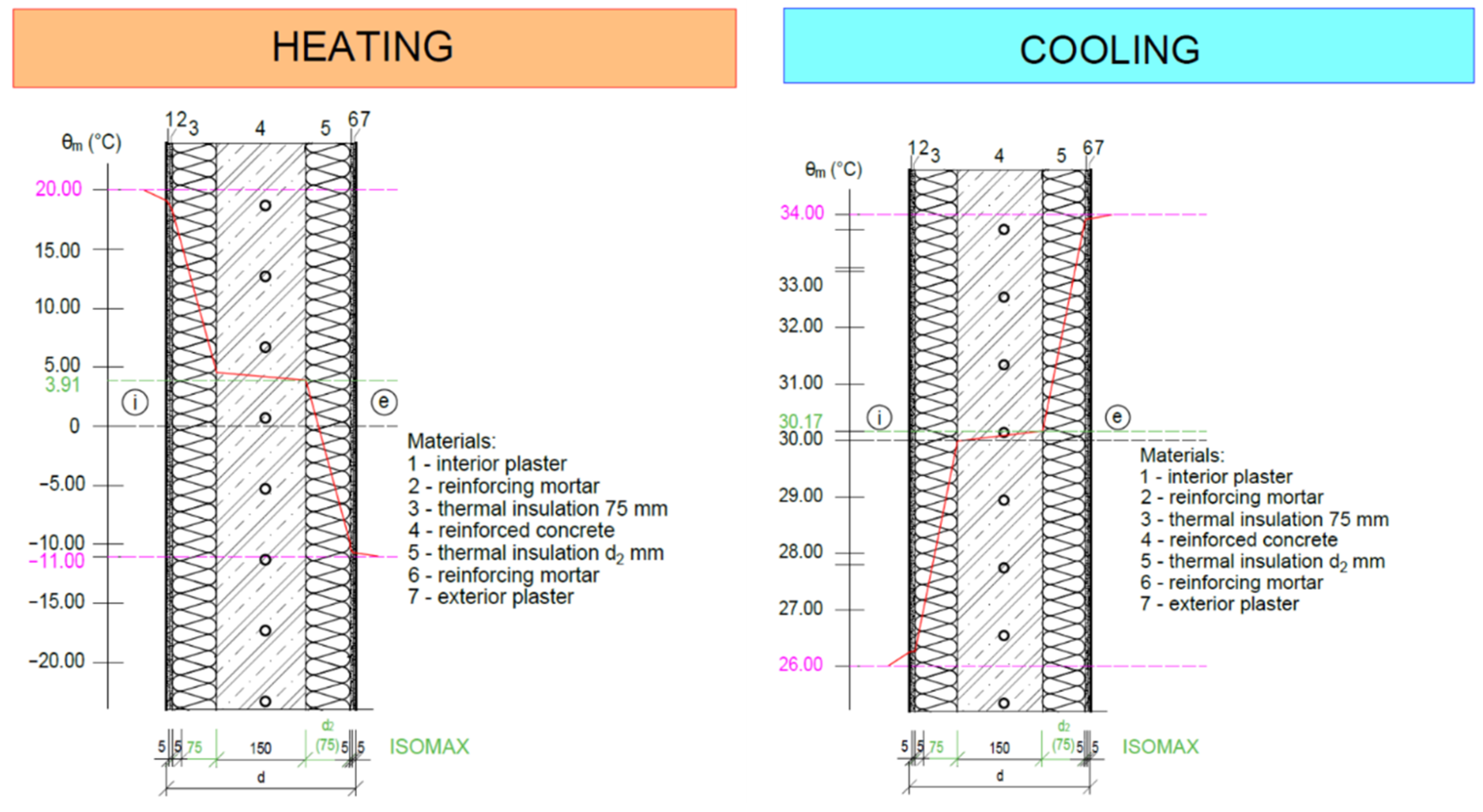
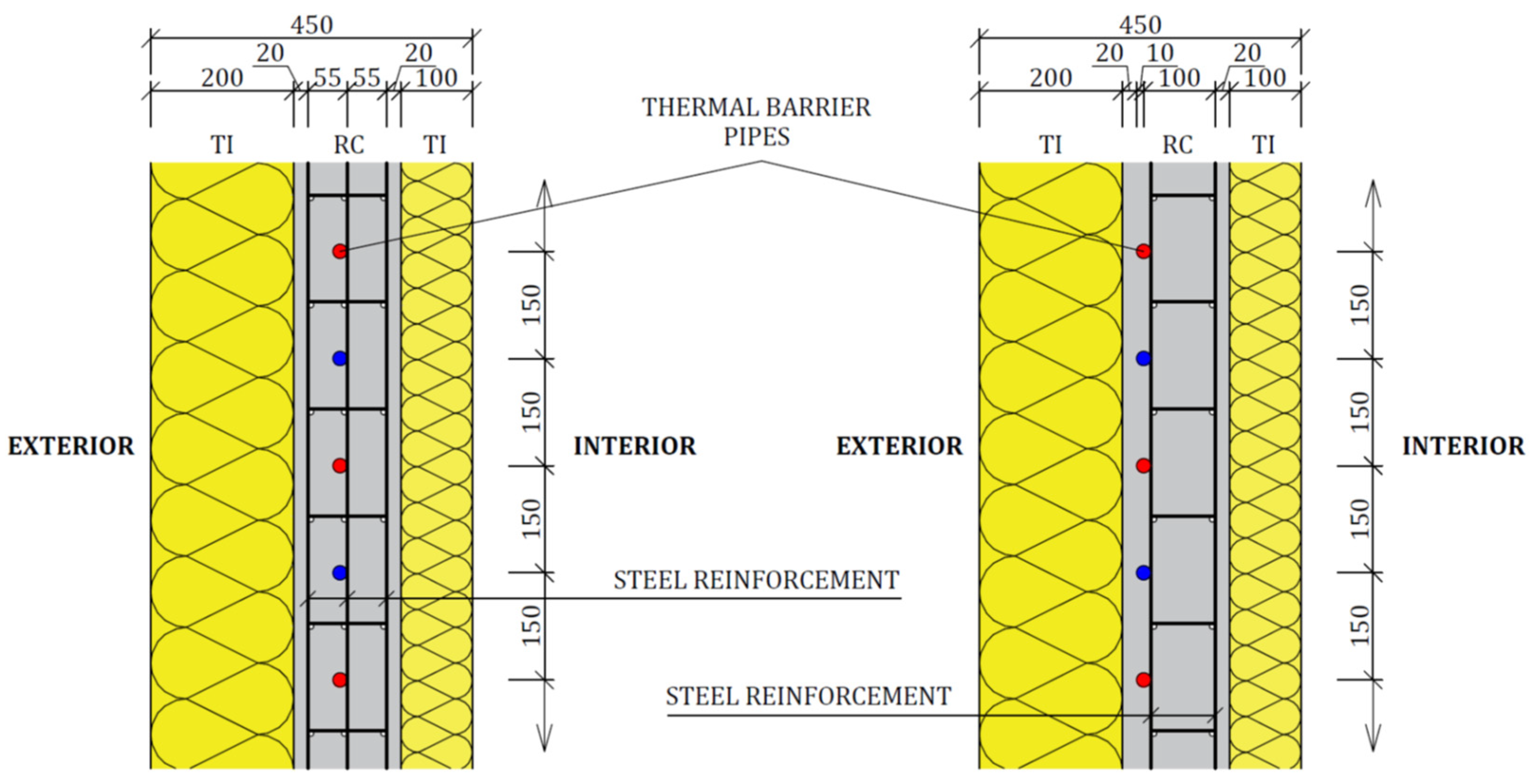
3.2. The Composition of the Patented ISOMAX Panel
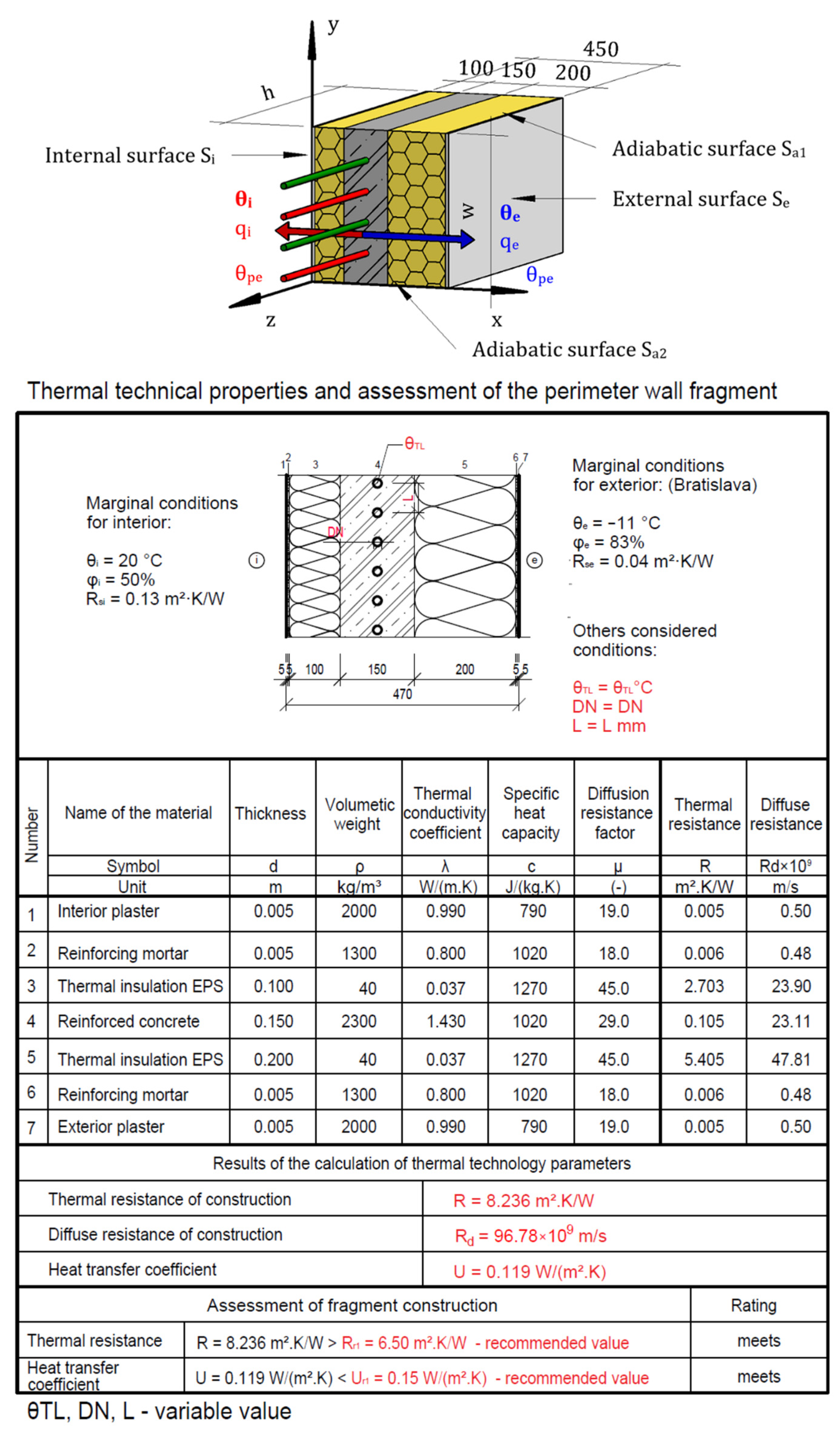
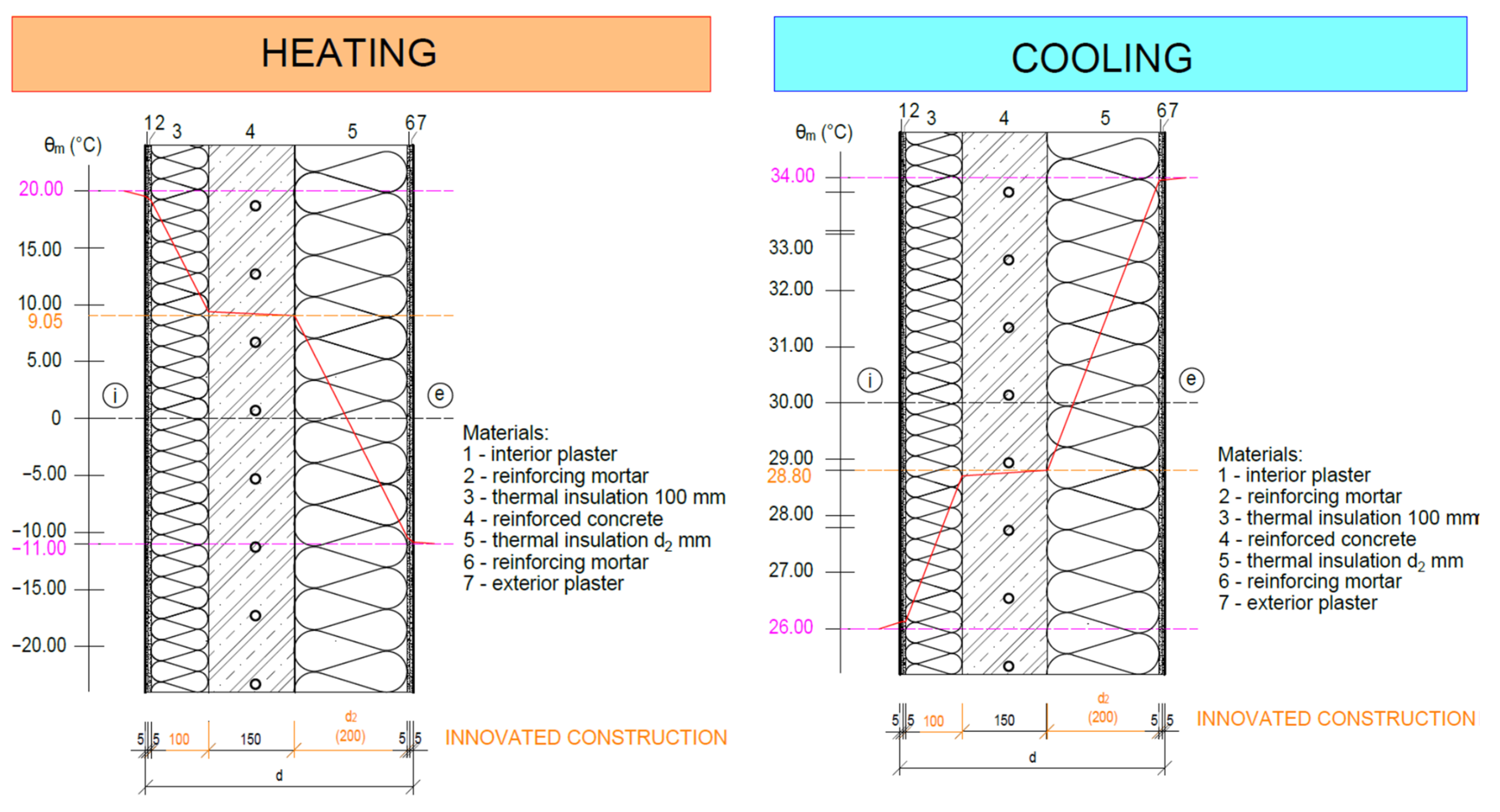
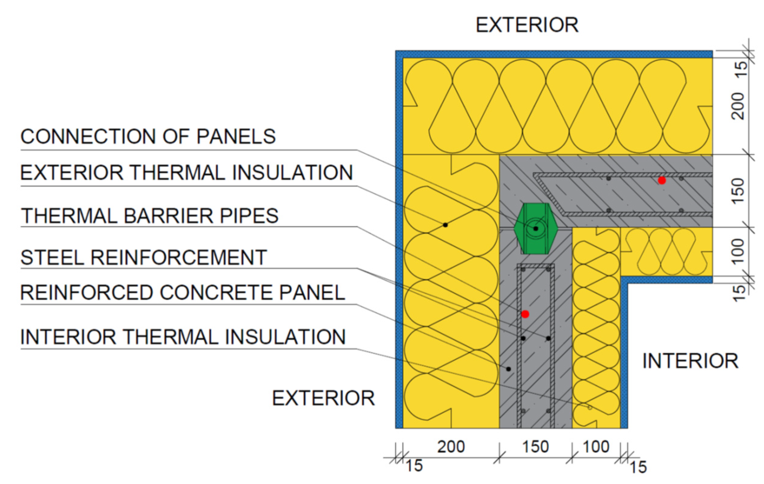
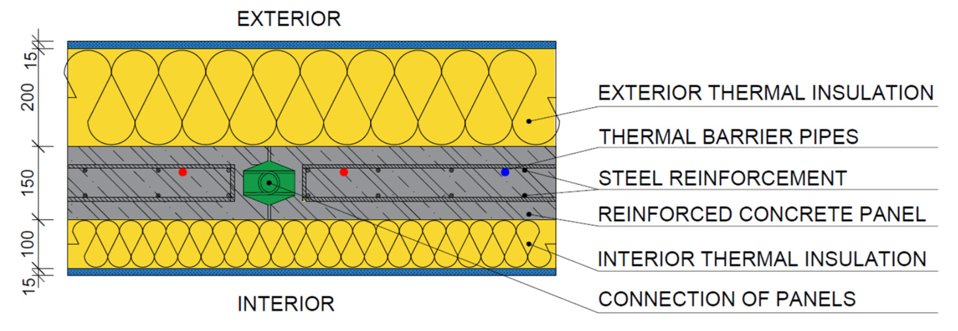
3.3. Analysis of the Design of an Innovative Panel with a Thermal Barrier
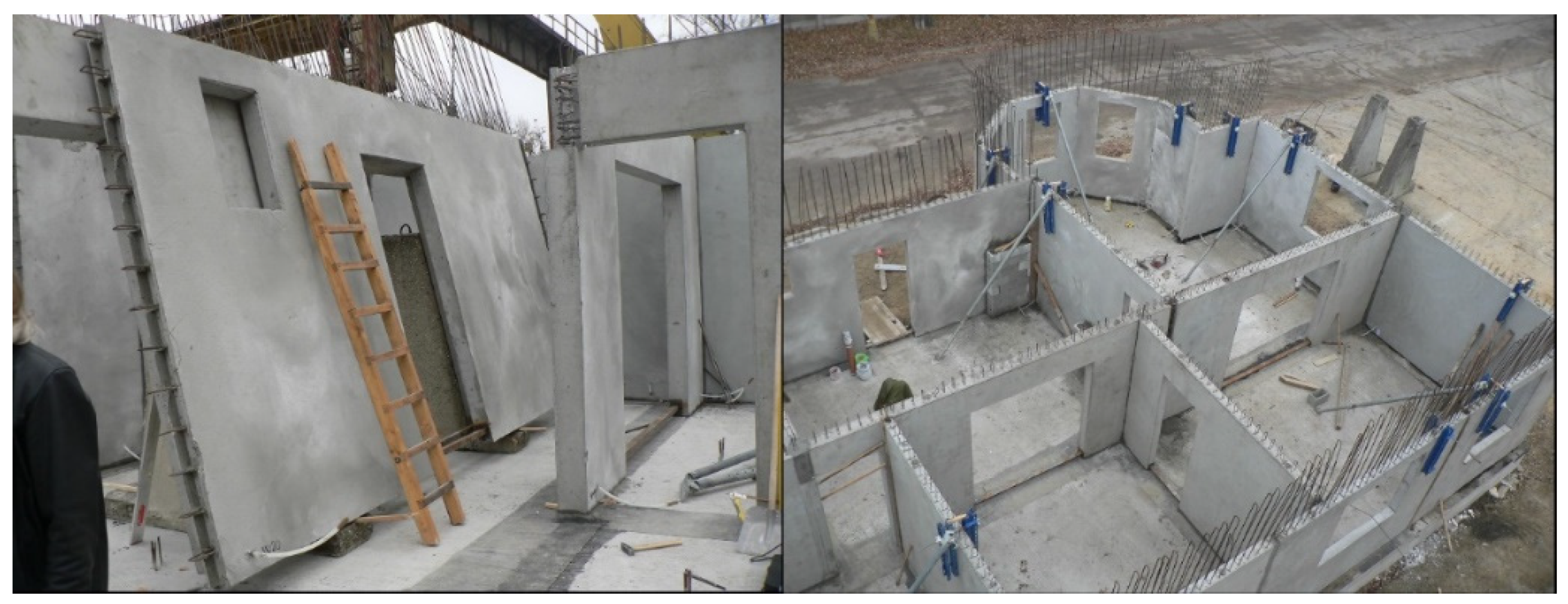
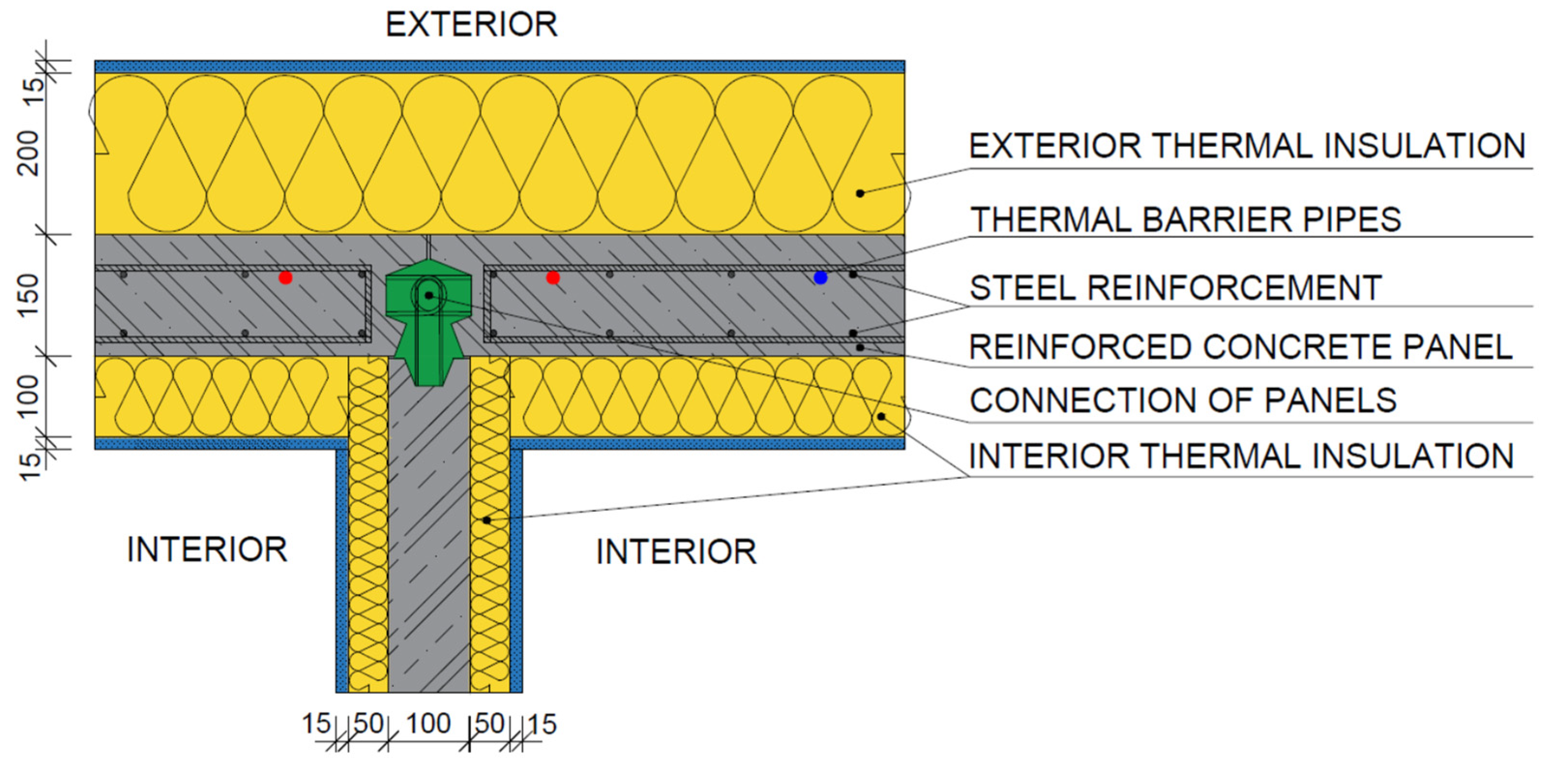
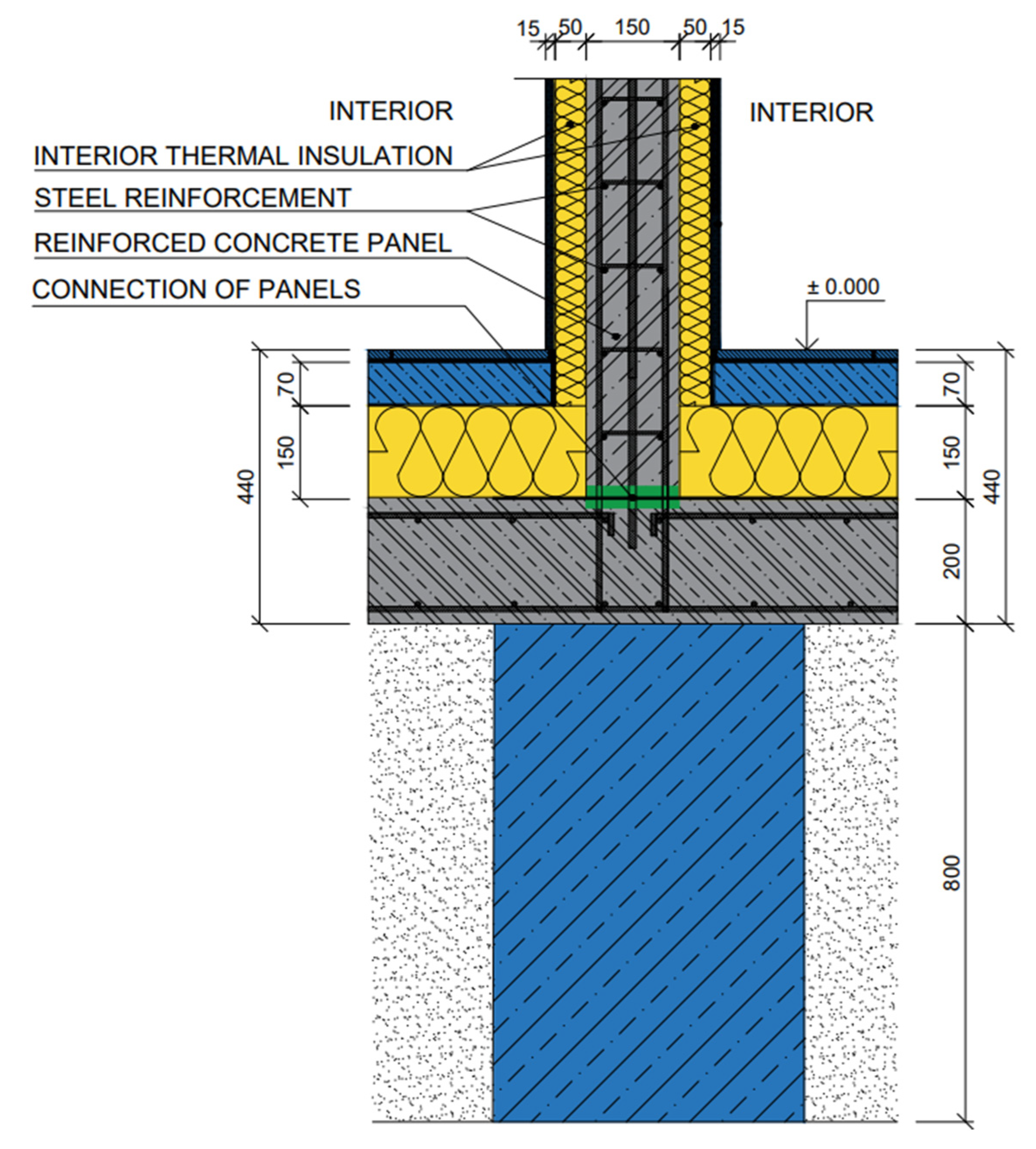
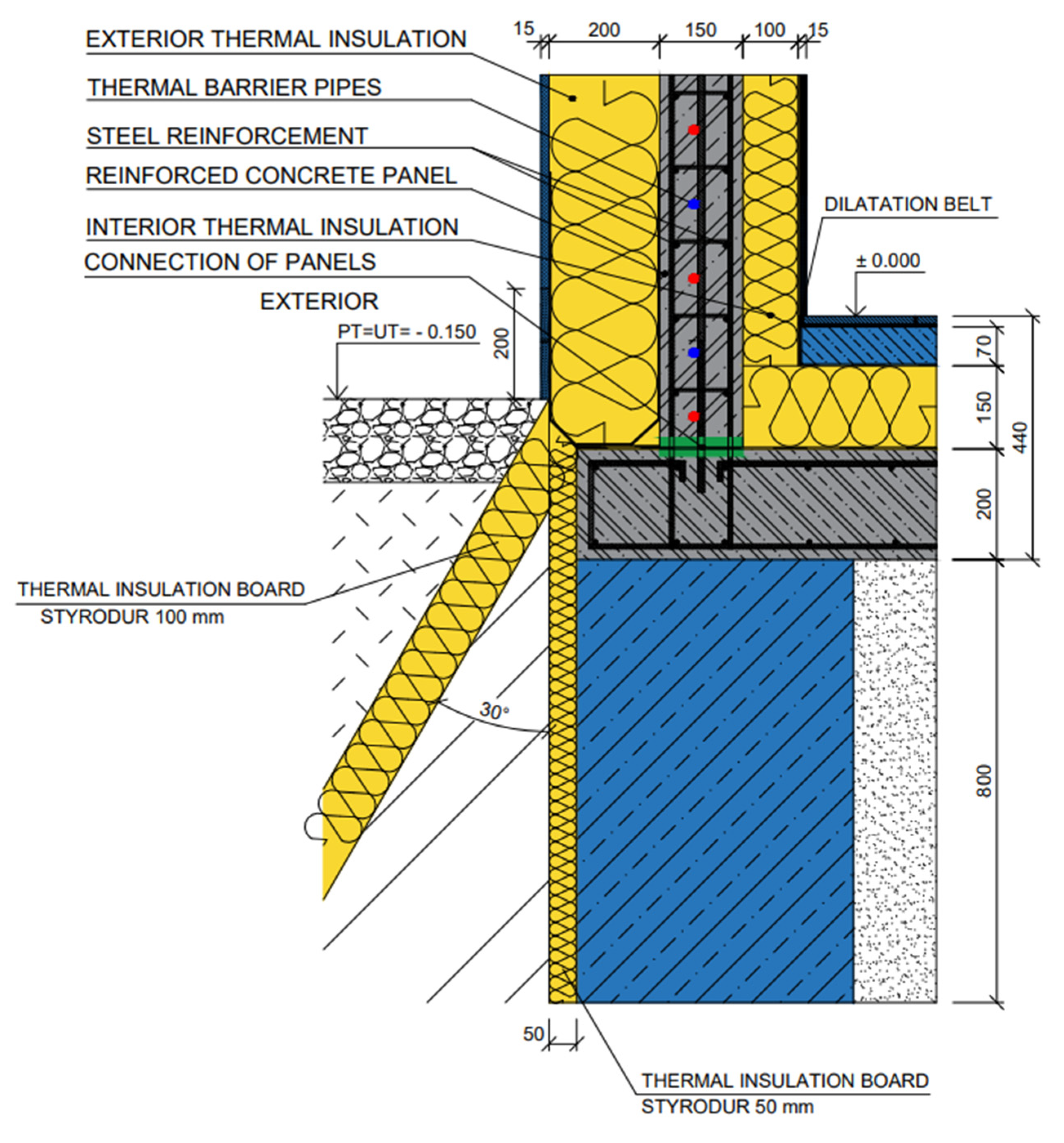
3.4. Details on Connecting Panels during Construction
4. Results and Discussion
- ▪
- Induction and analog form of forming an innovative panel with integrated energy-active elements.
- ▪
- Analysis of the energy potential of the retrofitted panel with a thermal barrier compared to the original panel.
- ▪
- Synthesis of the knowledge obtained from the scientific analysis and transformation of the data into the design and implementation of the IDA I prefabricated house prototype.
4.1. Inductive and Analogous Form of the Formation of the Innovative Panel with Integrated Energy-Active Elements
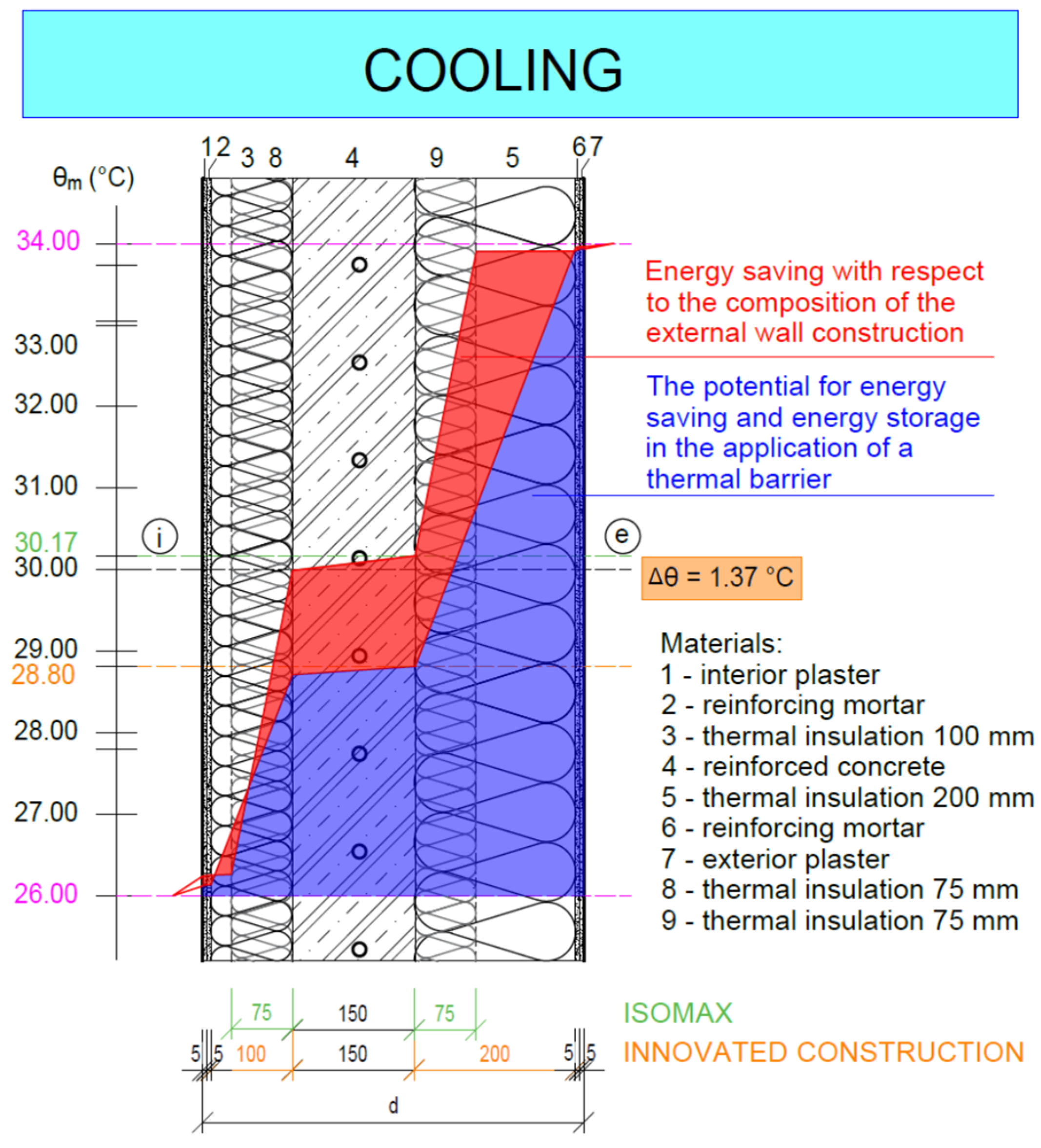
4.2. Analysis of the Energy Potential of the Retrofitted Panel with a Thermal Barrier Compared to the Original Panel
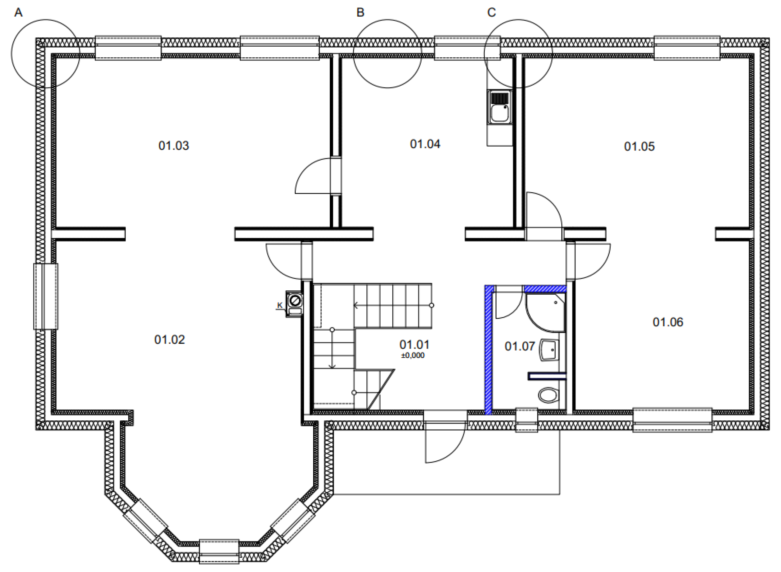
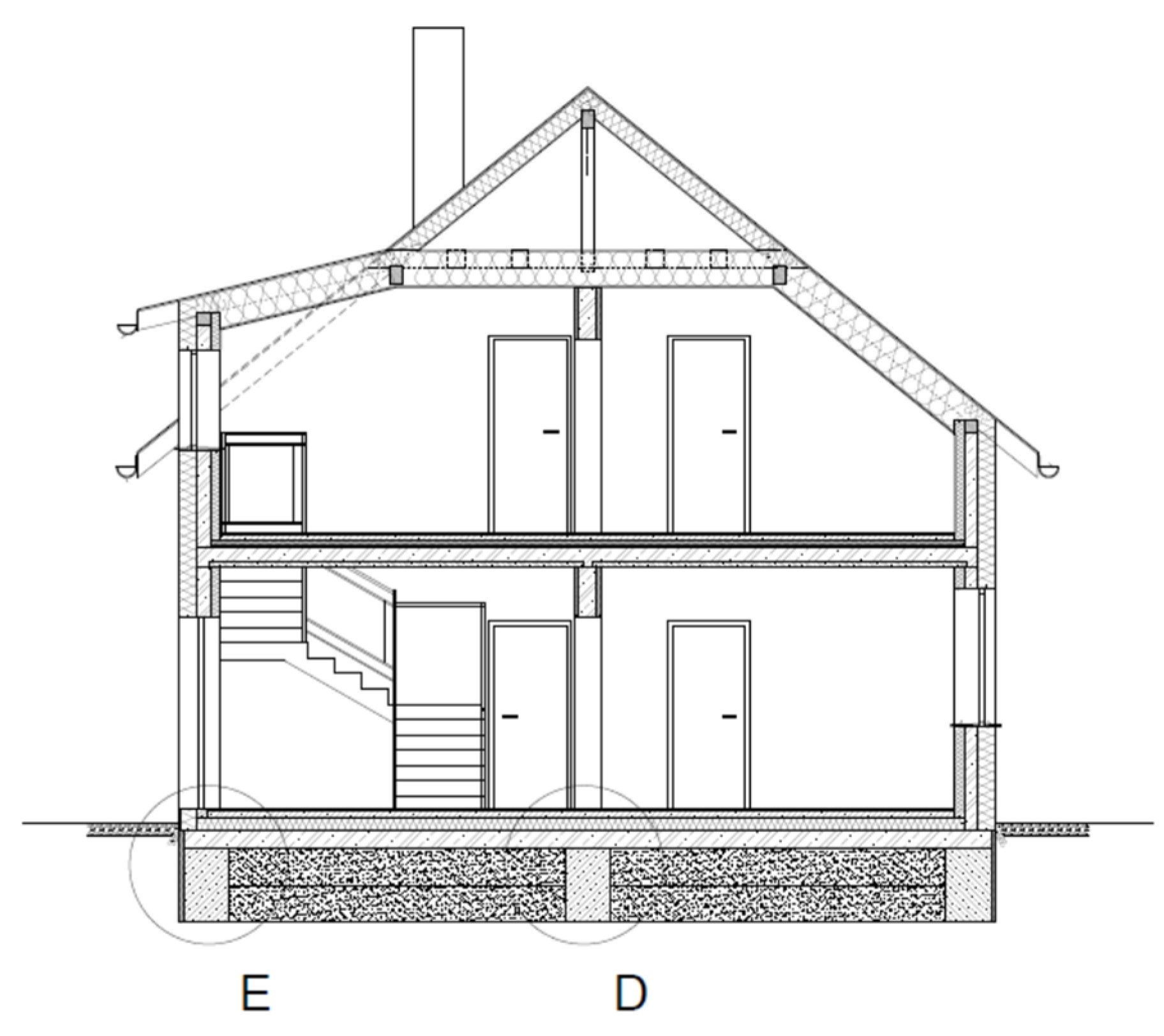
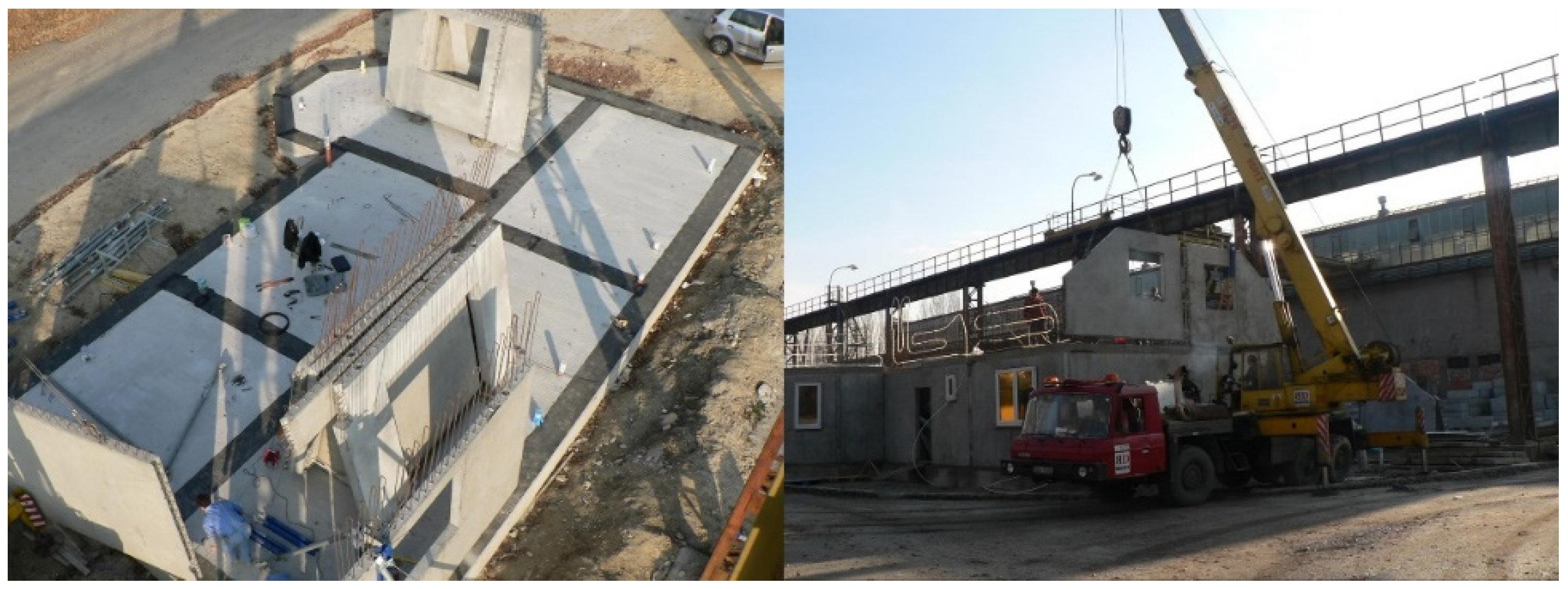
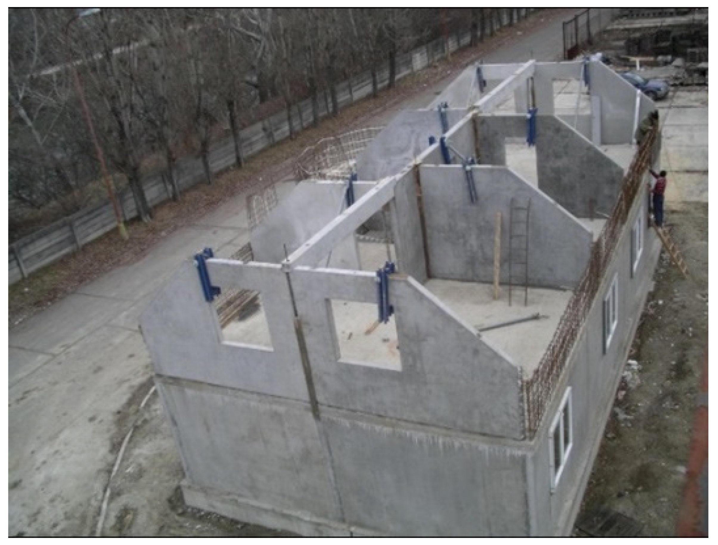
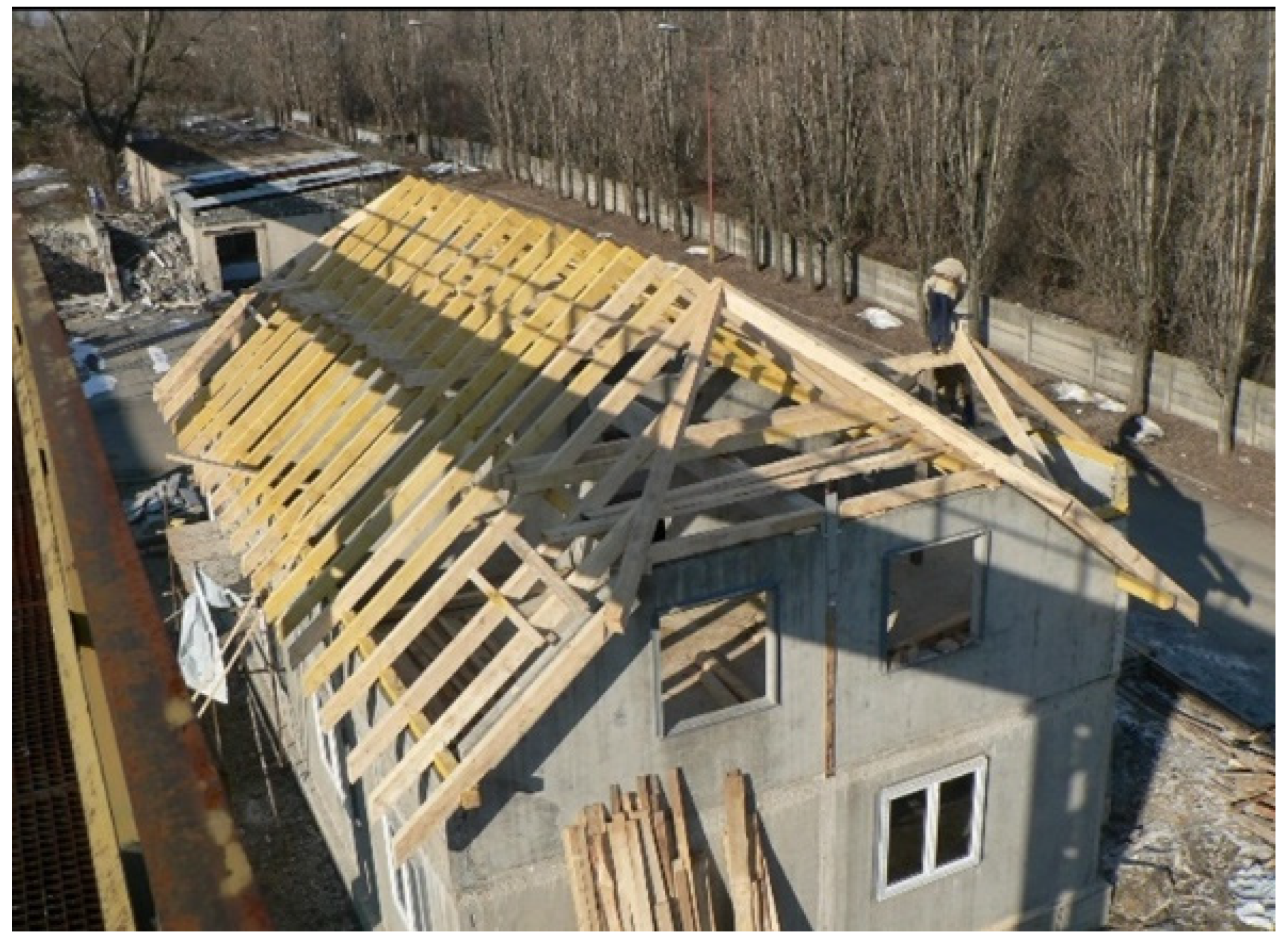
4.3. Synthesis of the Knowledge Obtained from the Scientific Analysis and Transformation of the Data into the Design and Implementation of the IDA I Prefabricated House Prototype
4.3.1. Structural System
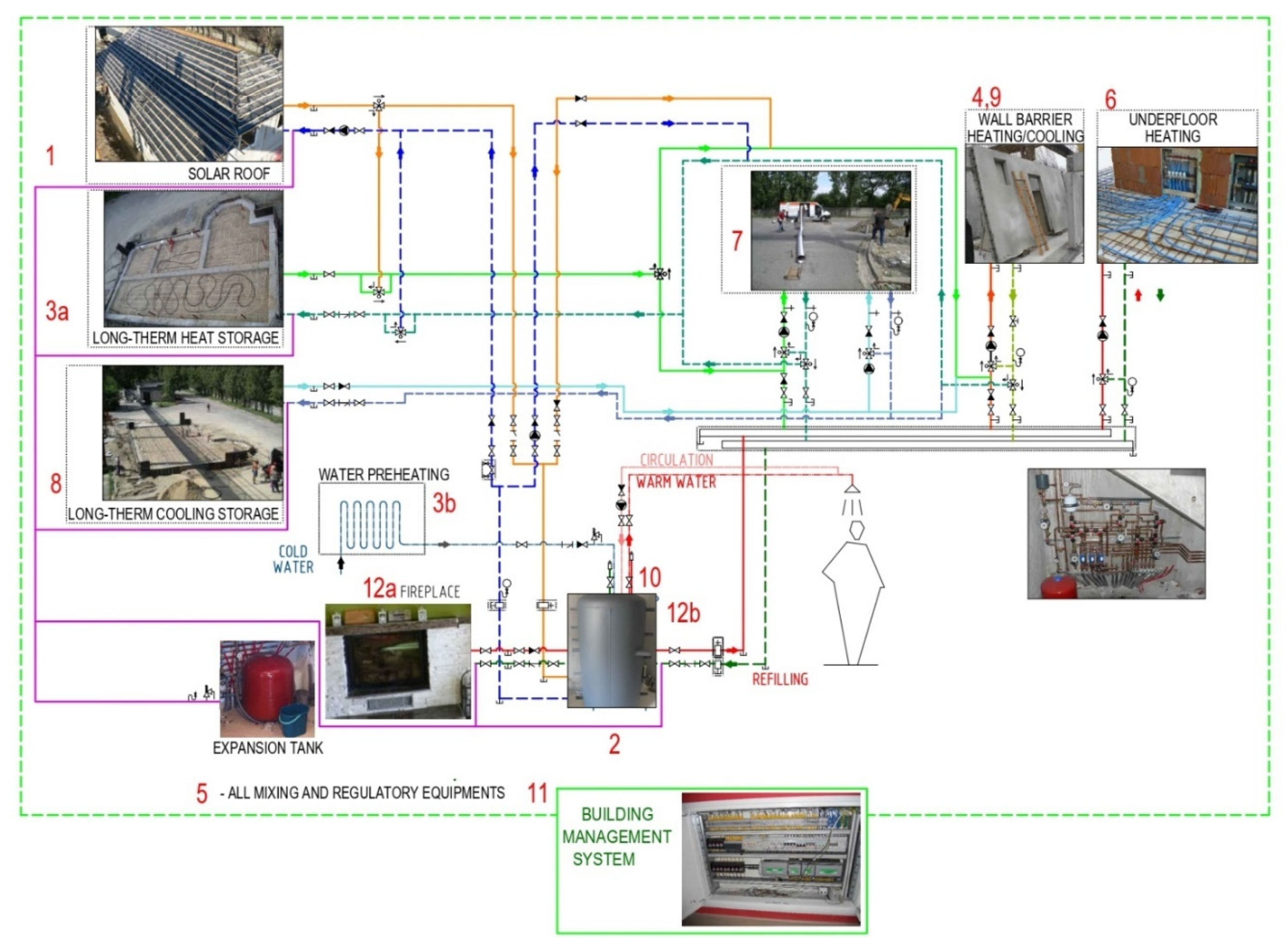
4.3.2. Energy System
5. Conclusions
- ▪
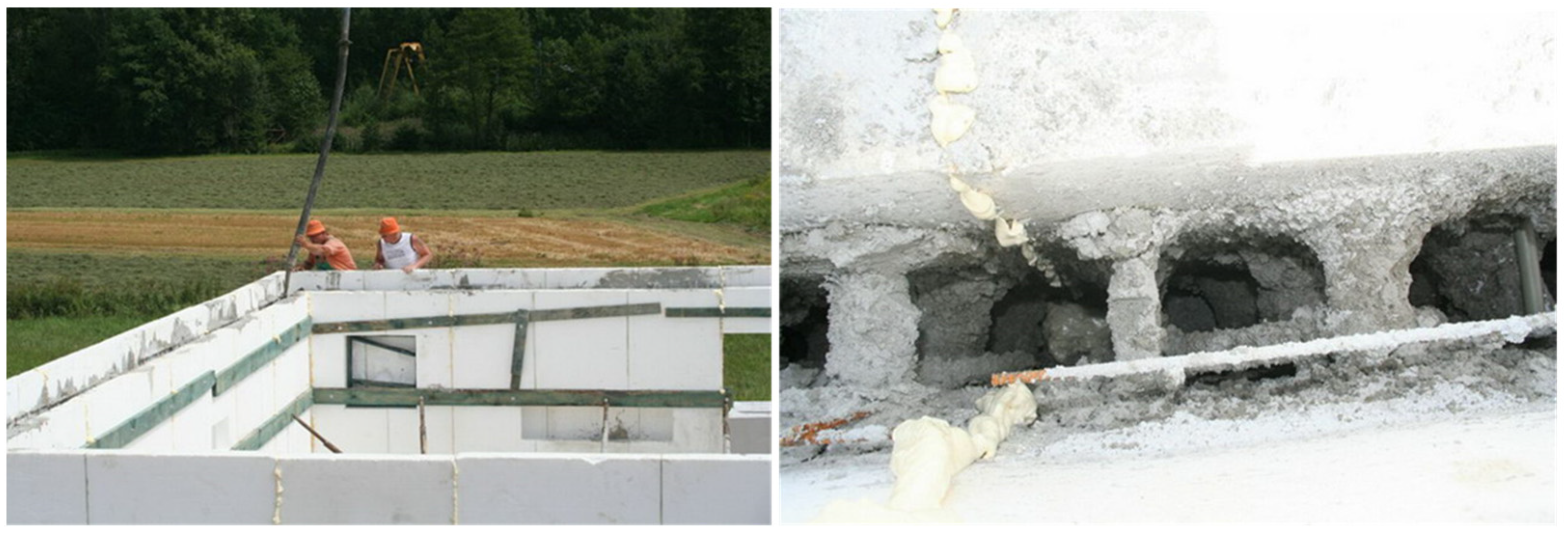
- The analysis and synthesis of the knowledge from the production and implementation of ISOMAX panels have determined the shortcomings of these panels. We have designed and developed innovative panels that eliminate the lengthy and complicated production as well as on-site implementation. We eliminated the static problems associated with insufficient concrete compaction when the original panels were poured on-site by fabricating the panels on vibratory tables in the panel factory;
- ▪
- The thermal barrier is one of the functions of building structures with integrated energy-active elements;
- ▪
- From the review of the scientific literature, it is clear that this is a very progressive area of research. So far, most studies on active thermal protection are based on calculations, computer simulations, and experimental measurements. Few studies have focused on the economic and environmental aspects of the use of active thermal protection;
- ▪
- For the analysis of both the ISOMAX panel and the upgraded panel, we developed mathematical–physical models and analyzed the energy potential of both panels based on a parametric study;
- ▪
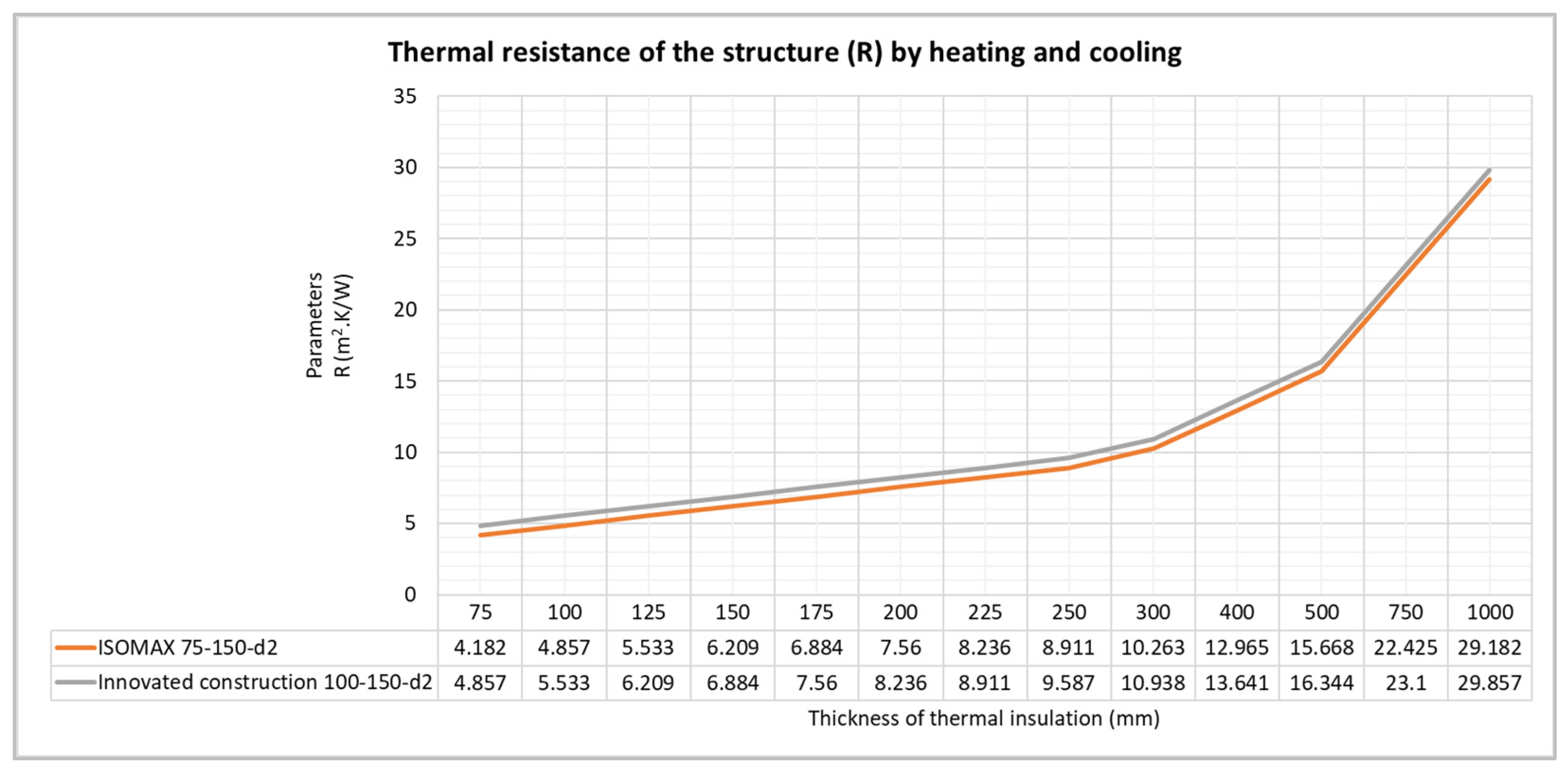
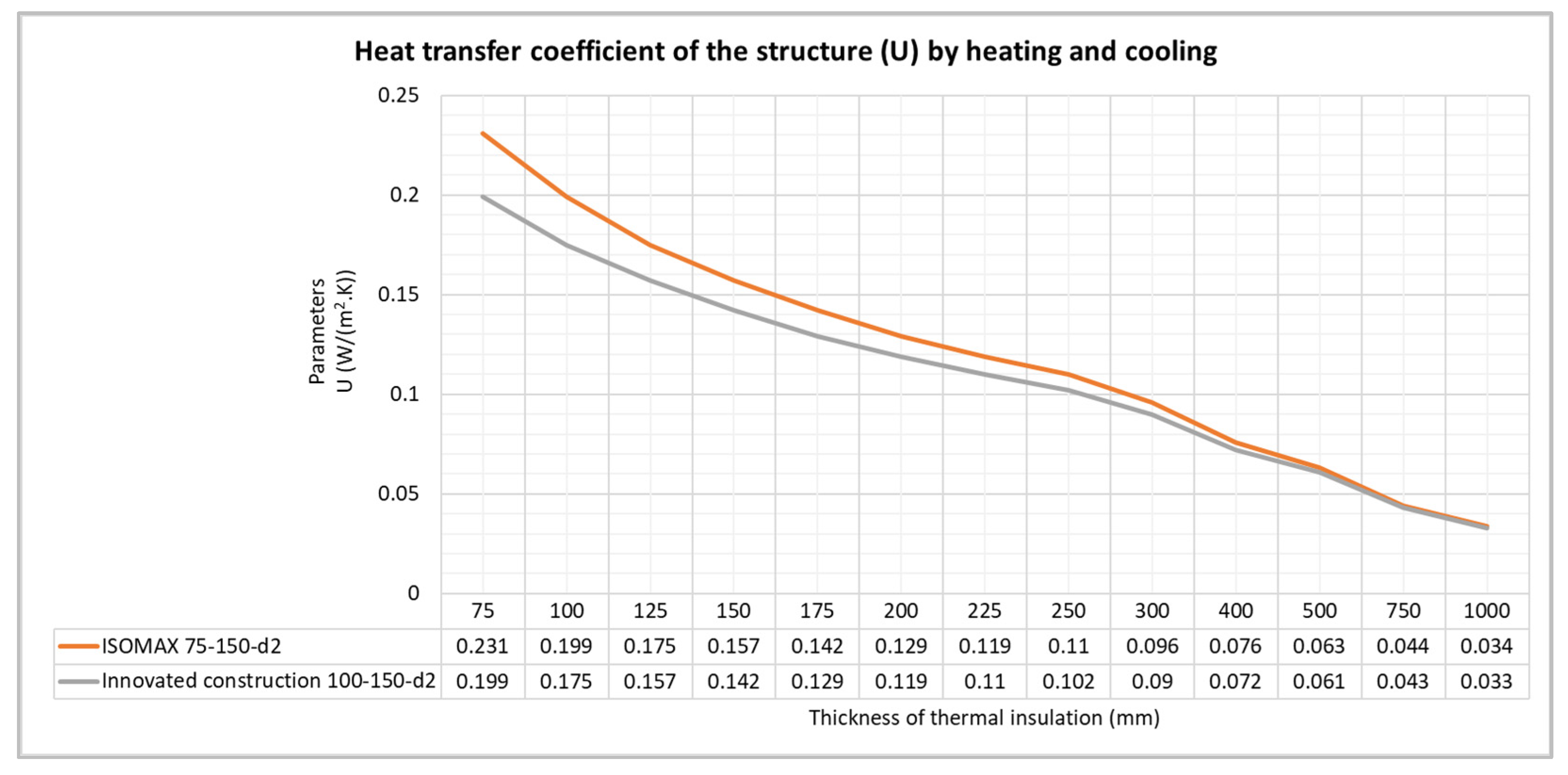
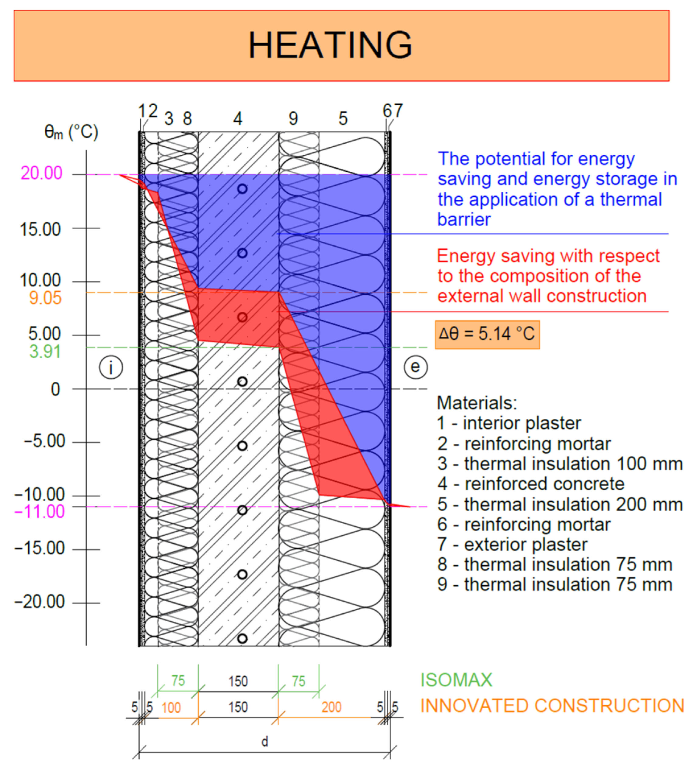
- The analysis shows that, for example, a mean temperature of θTB (°C) = +15 °C in the thermal barrier layer of this panel design during heating represents the equivalent thermal resistance Requivalent ((m2·K)/W) or equivalent heat transfer coefficient Uequivalent (W/(m2·K)) of the panel—as would be achieved with a 500 mm thick exterior thermal insulation. By analogy, this can be applied to the cooling period, where a mean temperature of θTB (°C) = +27 °C in the thermal barrier layer for this panel design represents an external thermal insulation thickness of 500 mm;
- ▪
- The energy analysis and design of the upgraded thermal barrier panel show an energy potential of the thermal barrier and heat/cold accumulation in the mass of the reinforced concrete load-bearing part of the panel. The potential was up to 2.6 times higher than that of the panel in the original ISOMAX design of the system;
- ▪
- The results of the analysis of the innovative panel design with integrated energy-active elements show high potential for the use of RES and waste heat with the technology;
- ▪
- In addition to a higher equivalent thermal resistance compared to the ISOMAX panel, our innovative building envelope panel has significantly lower requirements for the operation of the circulators, making the building’s energy intensity lower, more economically efficient, and more environmentally friendly;
- ▪
- The ISOMAX panels and the innovative panels with integrated energy-active elements only fulfil the energy functions of a thermal barrier and heat/cold storage. The design of building envelope panels (by application without external thermal insulation) offers additional energy functions, namely low-temperature radiant heating and high-temperature radiant cooling;
- ▪
- Further variants of the self-supporting thermal insulation panels for systems with active heat transfer control are presented in the utility model SK 5729 Y1 [25];
- ▪
- Among the most significant results and novelty of our research in this area can be considered the realization of the prototype of the prefabricated house IDA I.
- Develop further design variants of thermal insulation envelope panels with integrated energy-active elements.
- Develop a methodology for the installation of envelope panels with ATP.
- Implement selected types of perimeter thermal insulation panels with integrated energy-active elements on a laboratory building.
- Apply the proposed calculation methodology, selection, and assessment for selected combined building-energy systems using RES in buildings.
- Conduct experimental measurements of selected types of building envelope thermal insulation panels with integrated energy-active elements using RES as part of a laboratory building object in different operating modes.
- Measure usable energy of selected types of thermal insulation panels with integrated energy-active elements using RES in the application of active thermal protection in the functions of thermal barriers, cooling, and preparation of TV or heating water.
- Measure the efficiency of selected types of thermal insulation panels with integrated energy-active elements using RES in the application of active thermal protection for the elimination of overheating of the envelope and the interior depending on the intensity of solar radiation, shading, and the outdoor temperature.
- Develop software for designing, calculating, and assessing envelope thermal insulation panels with integrated RES-using active elements.
- Develop a methodology for applying building envelope thermal insulation panels with integrated RES energy components in a building information modeling (BIM) model.
- Ensure the automated transfer of the proposed database of envelope thermal insulation panels with integrated energy-active elements using RES to the BIM model.
- Verify the proposed solution on a concrete building project created in the BIM model.
6. Patents
Author Contributions
Funding
Institutional Review Board Statement
Informed Consent Statement
Data Availability Statement
Acknowledgments
Conflicts of Interest
References
- Kalús, D. The Contract for Work HZ 04–309–05—Design of a Passive House Using Solar and Geothermic Energy; K–TZB SvF STU: Bratislava, Slovakia, 2006. [Google Scholar]
- Available online: http://www.isomax-terrasol.eu/home.html (accessed on 20 June 2022).
- Lehmann, B.; Dorer, V.; Koschenz, M. Application range of thermally activated building systems tabs. Energy Build. 2007, 39, 593–598. [Google Scholar] [CrossRef]
- Gwerder, M.; Lehmann, B.; Tödtli, J.; Dorer, V.; Renggli, F. Control of thermally-activated building systems (TABS). Appl. Energy 2008, 85, 565–581. [Google Scholar] [CrossRef]
- Rijksen, D.O.; Wisse, C.J.; Van Schijndel, A.W.M. Reducing peak requirements for cooling by using thermally activated building systems. Energy Build. 2010, 42, 298–304. [Google Scholar] [CrossRef]
- Krzaczek, M.; Kowalczuk, Z. An effective control system for heating and cooling in residential buildings using Thermal Barrier. Build. Environ. 2010. [Google Scholar]
- Lehmann, B.; Dorer, V.; Gwerder, M.; Renggli, F.; Tödtli, J. Thermally activated building systems (TABS): Energy efficiency as a function of control strategy, hydronic circuit topology and (cold) generation system. Appl. Energy 2011, 88, 180–191. [Google Scholar] [CrossRef]
- Stojanovic, B.; Janevski, J.; Mitkovic, P.; Stojanovic, M.; Ignjatovic, M. Thermally activated building systems in the context of increasing the energy efficiency of buildings. Therm. Sci. 2014, 18, 1011–1018. [Google Scholar] [CrossRef]
- Jan, B.; Georgios, V. Thermally Activated Building System (TABS): Efficient cooling and heating of commercial buildings. In Proceedings of the Climamed, Juan-Les-Pins, France, 10 September 2015. [Google Scholar]
- Yu, Y.; Niu, F.; Guo, H.-A.; Woradechjumroen, D. A thermo-activated wall for load reduction and supplementary cooling with free to low-cost thermal water. Energy 2016, 99, 250–265. [Google Scholar] [CrossRef] [Green Version]
- Kisilewicz, T.; Fedorczak-Cisak, M.; Barkanyi, T. Active thermal insulation as an element limiting heat loss through external walls. Energy Build. 2019, 205, 109541. [Google Scholar] [CrossRef]
- Figiel, E.; Leciej-Pirczewska, D. Outer wall with thermal barrier. Impact of the barrier on heat losses and CO2 emissions. Prz. Nauk. Inż. Kształt. Śr. 2020, 29, 223–233. [Google Scholar] [CrossRef]
- Kalús, D.; Gašparík, J.; Janík, P.; Kubica, M.; Šťastný, P. Innovative building technology implemented into facades with active thermal protection. Sustainability 2021, 13, 4438. [Google Scholar] [CrossRef]
- Kalús, D.; Janík, P.; Koudelková, D.; Mučková, V.; Sokol, M. Contribution to research on ground heat storages as part of building energy systems using RES. Energy Build. 2022, 267, 112125. [Google Scholar] [CrossRef]
- Maruyama, S.; Viskanta, R.; Aihara, T. Active thermal protection system against intense irradiation. J. Thermophys. Heat Transf. 1989, 3, 389–394. [Google Scholar] [CrossRef]
- Olesen, B.W.; De Carli, M.; Scarpa’s, M.; Koschenz, M. Dynamic Evaluation of the Cooling Capacity of Thermo-Active Building Systems. ASHRAE Trans. 2006, 112, 350–357. [Google Scholar]
- Krecké, E.; Ulbrich, R.; Radlak, G. Connection of solar and near-surface geothermal energy in Isomax technology. In Proceedings of the CESB 07 PRAGUE Conference, Prague, Czech Republic, 24–26 September 2007; pp. 622–628. [Google Scholar]
- Gwerder, M.; Tödtli, J.; Lehmann, B.; Dorer, V.; Güntensperger, W.; Renggli, F. Control of thermally activated building systems (TABS) in intermittent operation with pulse width modulation. Appl. Energy 2009, 86, 1606–1616. [Google Scholar] [CrossRef]
- Xie, J.; Zhu, Q.; Xu, X. An active pipe-embedded building envelope for utilizing low-grade energy sources. J. Cent. South Univ. Technol. 2012, 19, 1663–1667. [Google Scholar] [CrossRef]
- Doležel, M. Alternative Way of Thermal Protection by Thermal Barrier. AMR 2014, 899, 107–111. [Google Scholar] [CrossRef]
- Ibrahim, M.; Wurtz, E.; Anger, J.; Ibrahim, O. Experimental and numerical study on a novel low temperature façade solar thermal collector to decrease the heating demands: A south-north pipe-embedded closed-water-loop system. Sol. Energy 2017, 147, 22–36. [Google Scholar] [CrossRef]
- K-TZB SvF STU. The contract for work HZ 04-210-05. In Assessment of Thermal Comfort State in an Experimental House; K-TZB SvF STU: Bratislava, Slovakia, 2006. [Google Scholar]
- STN 73 0540-2 + Z1 + Z2: Thermal Protection of Buildings. In Thermal Performance of Buildings and Components. Part 2: Functional Requirements; Úrad pre Normalizáciu, Metrológiu a Skúšobníctvo Slovenskej Republiky: Bratislava, Slovak Republic, 2019.
- Krzaczek, M.; Kowalczuk, Z. Thermal Barrier as a technique of indirect heating and cooling for residential buildings. Energy Build. 2011, 43, 823–837. [Google Scholar] [CrossRef]
- Available online: https://wbr.indprop.gov.sk/WebRegistre/Patent/Detail/5018-2010 (accessed on 20 June 2022).
- Available online: https://wbr.indprop.gov.sk/WebRegistre/Patent/Detail/5014-2010 (accessed on 20 June 2022).
- Available online: https://wbr.indprop.gov.sk/WebRegistre/Patent/Detail/5019-2010 (accessed on 20 June 2022).
- Available online: https://patents.google.com/patent/WO2011146025A1/und (accessed on 20 June 2022).


| Heating by ISOMAX 75–150-d2 | |||||||||||||
|---|---|---|---|---|---|---|---|---|---|---|---|---|---|
| d2 (mm) | 75 | 100 | 125 | 150 | 175 | 200 | 225 | 250 | 300 | 400 | 500 | 750 | 1000 |
| R (m2·K/W) | 4.182 | 4.857 | 5.533 | 6.209 | 6.884 | 7.560 | 8.236 | 8.911 | 10.263 | 12.965 | 15.668 | 22.425 | 29.182 |
| U (W/(m2·K)) | 0.231 | 0.199 | 0.175 | 0.157 | 0.142 | 0.129 | 0.119 | 0.110 | 0.096 | 0.076 | 0.063 | 0.044 | 0.034 |
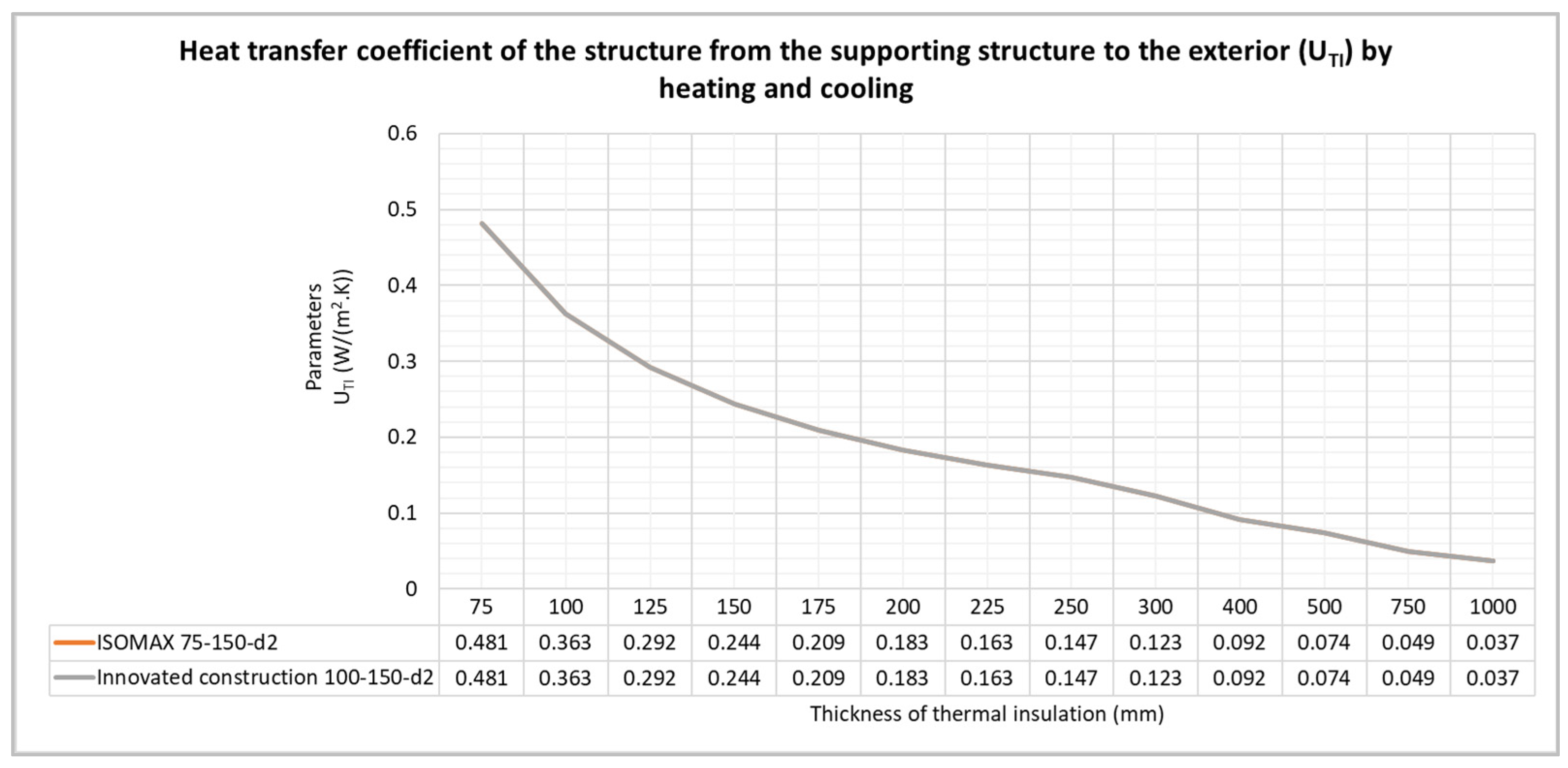
| UTI (m2·K/W)) | 0.481 | 0.363 | 0.292 | 0.244 | 0.209 | 0.183 | 0.163 | 0.147 | 0.123 | 0.092 | 0.074 | 0.049 | 0.037 |
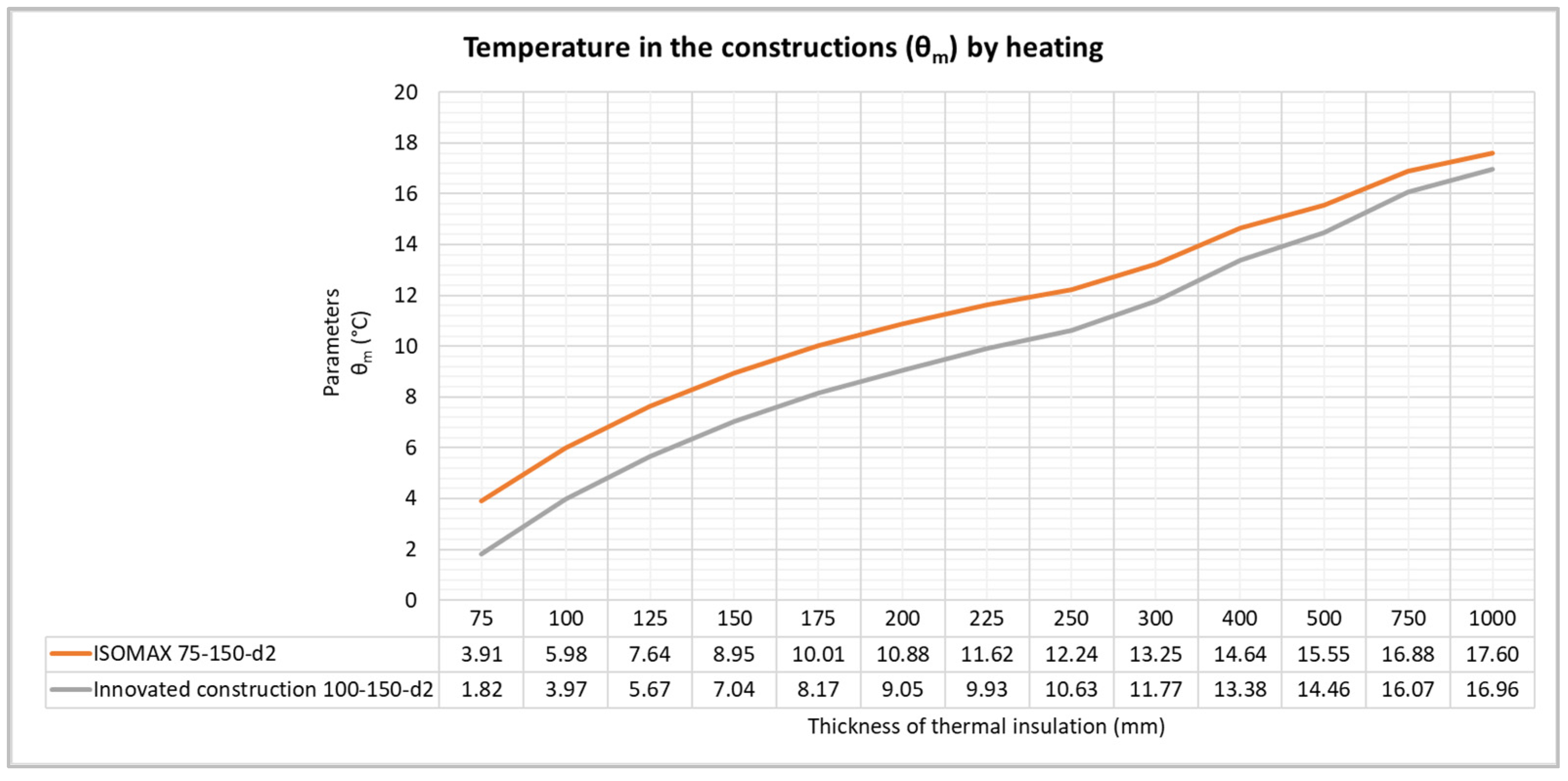
| θm (°C) | 3.91 | 5.98 | 7.64 | 8.95 | 10.01 | 10.88 | 11.62 | 12.24 | 13.25 | 14.64 | 15.55 | 16.88 | 17.60 |
| Cooling by ISOMAX 75–150-d2 | |||||||||||||
|---|---|---|---|---|---|---|---|---|---|---|---|---|---|
| d2 (mm) | 75 | 100 | 125 | 150 | 175 | 200 | 225 | 250 | 300 | 400 | 500 | 750 | 1000 |
| R (m2·K/W) | 4.182 | 4.857 | 5.533 | 6.209 | 6.884 | 7.560 | 8.236 | 8.911 | 10.263 | 12.965 | 15.668 | 22.425 | 29.182 |
| U (W/(m2·K)) | 0.231 | 0.199 | 0.175 | 0.157 | 0.142 | 0.129 | 0.119 | 0.110 | 0.096 | 0.076 | 0.063 | 0.044 | 0.034 |
| UTI (m2·K/W)) | 0.481 | 0.363 | 0.292 | 0.244 | 0.209 | 0.183 | 0.163 | 0.147 | 0.123 | 0.092 | 0.074 | 0.049 | 0.037 |
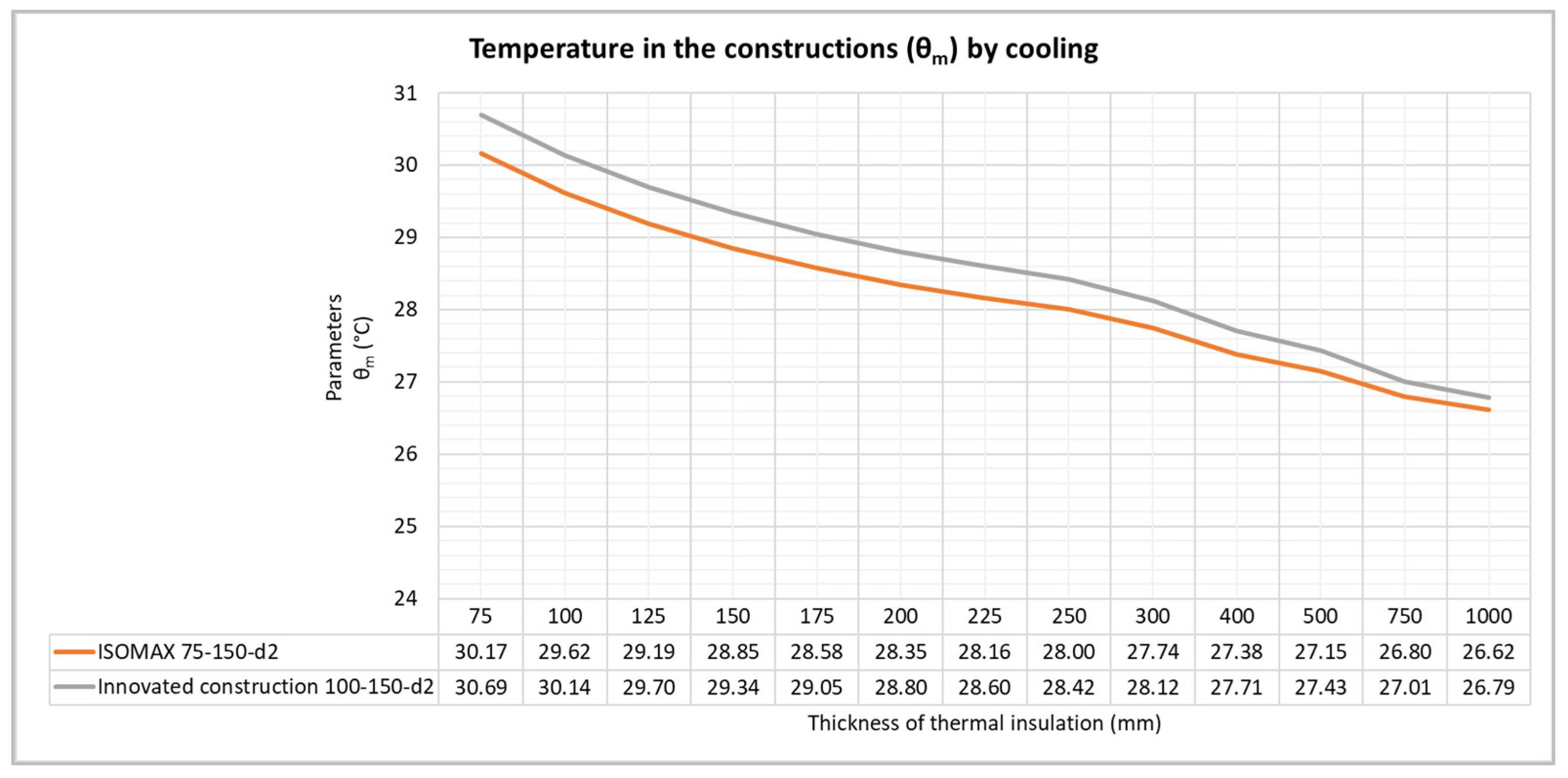
| θm (°C) | 30.17 | 29.62 | 29.19 | 28.85 | 28.58 | 28.35 | 28.16 | 28.00 | 27.74 | 27.38 | 27.15 | 26.80 | 26.62 |
| Heating by Innovated Construction 100–150-d2 | |||||||||||||
|---|---|---|---|---|---|---|---|---|---|---|---|---|---|
| d2 (mm) | 75 | 100 | 125 | 150 | 175 | 200 | 225 | 250 | 300 | 400 | 500 | 750 | 1000 |
| R (m2·K/W) | 4.857 | 5.533 | 6.209 | 6.884 | 7.560 | 8.236 | 8.911 | 9.587 | 10.938 | 13.641 | 16.344 | 23.100 | 29.857 |
| U (W/(m2·K)) | 0.199 | 0.175 | 0.157 | 0.142 | 0.129 | 0.119 | 0.110 | 0.102 | 0.090 | 0.072 | 0.061 | 0.043 | 0.033 |
| UTI (m2·K/W)) | 0.481 | 0.363 | 0.292 | 0.244 | 0.209 | 0.183 | 0.163 | 0.147 | 0.123 | 0.092 | 0.074 | 0.049 | 0.037 |
| θm (°C) | 1.82 | 3.97 | 5.67 | 7.04 | 8.17 | 9.05 | 9.93 | 10.63 | 11.77 | 13.38 | 14.46 | 16.07 | 16.96 |
| Cooling by Innovated Construction 100–150-d2 | |||||||||||||
|---|---|---|---|---|---|---|---|---|---|---|---|---|---|
| d2 (mm) | 75 | 100 | 125 | 150 | 175 | 200 | 225 | 250 | 300 | 400 | 500 | 750 | 1000 |
| R (m2·K/W) | 4.857 | 5.533 | 6.209 | 6.884 | 7.560 | 8.236 | 8.911 | 9.587 | 10.938 | 13.641 | 16.344 | 23.100 | 29.857 |
| U (W/(m2·K)) | 0.199 | 0.175 | 0.157 | 0.142 | 0.129 | 0.119 | 0.110 | 0.102 | 0.090 | 0.072 | 0.061 | 0.043 | 0.033 |
| UTI (m2·K/W)) | 0.481 | 0.363 | 0.292 | 0.244 | 0.209 | 0.183 | 0.163 | 0.147 | 0.123 | 0.092 | 0.074 | 0.049 | 0.037 |
| θm (°C) | 30.69 | 30.14 | 29.7 | 29.34 | 29.05 | 28.8 | 28.6 | 28.42 | 28.12 | 27.71 | 27.43 | 27.01 | 26.79 |
Publisher’s Note: MDPI stays neutral with regard to jurisdictional claims in published maps and institutional affiliations. |
© 2022 by the authors. Licensee MDPI, Basel, Switzerland. This article is an open access article distributed under the terms and conditions of the Creative Commons Attribution (CC BY) license (https://creativecommons.org/licenses/by/4.0/).
Share and Cite
Kalús, D.; Koudelková, D.; Mučková, V.; Sokol, M.; Kurčová, M. Contribution to the Research and Development of Innovative Building Components with Embedded Energy-Active Elements. Coatings 2022, 12, 1021. https://doi.org/10.3390/coatings12071021
Kalús D, Koudelková D, Mučková V, Sokol M, Kurčová M. Contribution to the Research and Development of Innovative Building Components with Embedded Energy-Active Elements. Coatings. 2022; 12(7):1021. https://doi.org/10.3390/coatings12071021
Chicago/Turabian StyleKalús, Daniel, Daniela Koudelková, Veronika Mučková, Martin Sokol, and Mária Kurčová. 2022. "Contribution to the Research and Development of Innovative Building Components with Embedded Energy-Active Elements" Coatings 12, no. 7: 1021. https://doi.org/10.3390/coatings12071021