Article

Gravure Printing for PVDF Thin-Film Pyroelectric Device Manufacture

Portici Research Centre, Italian National Agency for New Technologies, Energy and Sustainable Economic Development (ENEA), 80055 Portici, Italy
*
Authors to whom correspondence should be addressed.
Coatings 2022, 12(7), 1020; https://doi.org/10.3390/coatings12071020
Submission received: 30 June 2022 / Revised: 14 July 2022 / Accepted: 17 July 2022 / Published: 19 July 2022

Abstract

:
Pyroelectric energy harvesting is one of the more recent and promising solid-state approaches for directly converting time-dependent temperature fluctuations into electric energy. Conventional printing technologies can offer many advantages for the production of pyroelectric thin-film-based devices, such as low cost, low temperature, the use of flexible substrates and shaping at the same time as deposition. Nevertheless, some issues related to low printed thickness and film-forming microstructure control need to be addressed. In this exploratory study, the possibility of exploiting the highly attractive gravure printing process for the potential industrial manufacture of flexible polyvinylidene fluoride (PVDF) thin-film pyroelectric devices was investigated. By the use of corona pre-treatment of the printing substrate and low-temperature polar solvent evaporation, multilayer gravure-printed PVDF pyroelectric devices were successfully manufactured for the first time, achieving a maximum generated current of 0.1 nA at 2.5 K/s from a device with an active area of 1 cm2. Considering the very low thermal inertia and performance scaling by the area expected for pyroelectric thin-film-based devices, combined with the upscaling potential of roll-to-roll gravure printing, our results provide new opportunities for on-demand, low-cost pyroelectric device manufacture and their integration in hybrid harvesters.

Graphical Abstract

1. Introduction

With increase in environmental awareness and in the demand for self-powered electronics, energy-harvesting devices for converting wasted energy from ambient sources into useful electrical power supplies have recently become more and more a topic of study [1,2,3,4,5,6,7,8]. Although in such converters the scavenged energy is usually rather small (from nW to mW), their use starts to become feasible if applied to recently developed battery-free devices or to the extension of their battery lifetime [1,2,9,10,11,12]. In particular, the energy produced from such small energy generators is proposed as a local power source for many personal and wearable electronic devices, wireless sensors, and in emerging Internet of Things (IoT) applications, or connected to charge energy storage devices, such as supercapacitors and batteries [1,2,6,13,14,15,16,17,18]. Among potential energy sources, wasted heat remains one of the most attractive, since it is abundant, ubiquitous and easily accessible [3,17,19,20,21,22].
In the field of thermal energy harvesting, one of the more recent approaches involves the use of solid-state devices based on pyroelectric materials to directly convert temperature fluctuations into electric energy [19,20,22,23]. Pyroelectrics are a class of non-centrosymmetric polar crystals exhibiting spontaneous polarization at room temperature in the absence of an applied electric field [2,15,23,24,25]. The presence of spontaneous polarization in such materials implies the existence of a charge on their surfaces which can attract free charges [2,19,24]. Since the level of polarization varies as the temperature changes in the pyroelectrics, surface-bound charges become free (heating) or attracted (cooling) as a result of the temperature-dependent surface-charge density [26,27,28,29]. Therefore, if the pyroelectric is orthogonally sandwiched to its polar axis by two electrodes, under short circuit conditions, a generation of current ip can occur when the material undergoes temperature variation over time, as expressed by the following equation:
i p = p A d T d t ,
where p = d P s d T σ ,   E is the pyroelectric coefficient of the unclamped material defined as the change of its spontaneous polarization Ps with temperature when in constant stress σ and electric field E conditions, A is the surface area covered by the electrodes and d T d t is the rate of temperature change [9,23,26,27]. Equation (1) states that ip is independent of the material layer thickness and only scales with its active area as the current is only related to the surface charge [19]. Therefore, pyroelectric materials can be employed to fabricate low-power generators to be used under conditions of cyclic temperature variations [25,30].
Due to their high pyroelectric coefficient, single crystal materials are considered promising in pyroelectric applications. However, their high cost, expensive processing techniques and poor size scalability strongly restrict their adoption [27,29].
The interest in pyroelectric generators is due to their potential to operate at higher thermodynamic efficiency than thermoelectric generators [5,13,19,23,26,31] and to their enhanced suitability for thermal energy conversion at a small scale [15]. Even though promising, pyroelectric energy harvesting is a rather new field of research and there are still few studies, especially when compared to those on thermoelectrics, so that pyroelectric generators appear to be distant from possible prototyping [3,9,15,16,19,21,30,32,33,34,35].
Nevertheless, the physical characteristics of pyroelectric devices make them potentially compatible with established industrial printing processes for thin-film production, leading to several possible advantages [23]. Thin-film-based devices have a very large surface-to-volume ratio, which is useful for effective heat exchange, especially at high temperature oscillation frequencies [5,20,24], so that a thermal-to-electrical conversion efficiency of up to 50% can theoretically be achieved [13,16]. Printed thin-film technology is also suited to the realization of large area electrodes to which the generated current is proportional (see Equation (1)). Moreover, conventional printing technologies can offer unique additional benefits for functional thin-film deposition, such as low-cost, low-temperature processing, high-throughput, the use of flexible substrates and patterning/shaping at the same time as deposition [36,37,38,39], fulfilling the ever-increasing demand for device flexibility and customization [10,40]. To date, there have been few examples of the use of printing technologies for preparing pyroelectric films [41,42,43,44]. Nonetheless, the fine control of film-forming microstructure, necessary to meet pyroelectric polarization requirements, could easily become a challenge because printing is performed by processing polycrystalline materials from solution [45,46,47,48].
Based on these premises, in this exploratory study, we aimed to investigate the possibility of using printing technology as an innovative and cost-effective method for the potential industrial manufacture of future on-demand flexible thin-film pyroelectric devices.
For this purpose, due to its ability to couple very high-throughput and high resolution over a large area, the gravure printing method, widely used in industry, was chosen among different printing techniques because of its great potential in the manufacture of high quality material layers and devices [49,50,51,52]. Among available lead-free pyroelectric materials, polyvinylidene fluoride (PVDF) was selected, as it is potentially better suited for the testing purpose, having the typical advantages of polymers, such as low-temperature processability, low-cost and flexibility [2,29]. Semi-crystalline PVDF exhibits several phases, whose relative quantity strongly depends on film processing [2,8,53,54,55]. Among these, γ, and even more so, β polar phases are mostly recognized for providing a pyroelectric response [2,8,54,56,57,58,59,60], but they are thermodynamically less stable than the non-polar α phase and difficult to obtain [58,59,61]. Moreover, to achieve pyroelectric operation in PVDF films, a macroscopic polarization process must be performed to obtain the alignment of polarized covalent bonds in the polar phases [2,8,51]. This process, termed “poling”, is typically carried out by mechanical stretching at temperatures of 80–140 °C using a prolonged electric field of at least 100 kV·mm−1 at temperatures of 80–165 °C, or by electrospinning [8,51,62]. Although mechanical stretching is considered the preferred process in the industrial production of pyroelectric films [63], it is not compatible with direct film deposition on substrates [64].
Therefore, to enable the use of printing processes for the fabrication of PVDF-based pyroelectric devices, two main objectives were addressed: (i) to obtain crystalline polar phases in the printed PVDF film, and (ii) to orient dipoles normally to the substrate using methods compatible with solvent-based printing processes. To this purpose, PVDF crystallization by low temperature polar solvent evaporation and substrate corona pre-treatment were considered as the most suitable methods. To evaluate the effectiveness of the proposed methods, structural and functional characterizations of the printed films were carried out and are discussed.

2. Materials and Methods

Ink solutions were prepared by dissolving PVDF (Mw~180,000, Sigma Aldrich, St. Louis, MI, USA) under magnetic stirring in a mixture of dimethyl sulfoxide (DMSO) and acetone (Sigma Aldrich, St. Louis, MI, USA) with different solvent mixing ratios at concentrations ranging from 8 wt% to 15 wt% of PVDF.
The surface tension of the inks was measured by a contact angle OCA 20 system (DataPhysics Instruments GmbH, Filderstadt, Germany) in pendant drop configuration. The result for each type of ink was the average value of 10 repeated measurements carried out on each sample.
The viscosity of the inks was measured by a Viscometer (SV-10, A&D Europe Gmbh, Darmstadt, Germany) at a constant frequency of 30 Hz at 25 °C and ranged from 30 to 68 mPa·s for the 8 wt% and 15 wt% of PVDF in 50/50% w/w DMSO/acetone solution, respectively.
The electrical conductivity of the PVDF ink (12 wt%) was measured by a Conductivity MeterLab CDM210 (Radiometer Analytical, Hach, Lyon, France) obtaining 2.8 μS/cm.
The inks were gravure printed onto ITO (indium tin oxide) coated PET (polyethylene terephthalate) film and aluminum foil (both from Sigma Aldrich, St. Louis, MI, USA) using a commercial laboratory-scale gravure printer G1-5 (IGT, Almere, The Netherlands), equipped with a cylinder having a line density of 40 lines/cm, stylus angle of 120°, cell depth of 72 mm and screen angle of 53°. All the prints were performed in air. For multilayer printing, each layer was dried at 50 °C for 30 min before printing the next overlapped layer.
The thickness and the surface roughness (Sq) of the printed samples were investigated by a coherence-correlation interferometry-enabled surface-profiler (Taylor-Hobson, model CCI HD4K, Leicester, UK) and by a stylus profiler (KLA, model Tencor P-7, Milpitas, CA, USA).
The corona pre-treatment was performed on the PET-ITO substrate to increase its surface energy using a LabTEC Lab System (Tantec, Lunderskov, Denmark) equipped with a high frequency generator (range of 25–35 kHz). Contact angle measurements were carried out using the OCA-20 system in sessile drop configuration using single drops of water and diiodomethane of 0.5 µL. The final water and diiodomethane contact angle values were the average of 10 measurements carried out on each sample. The total surface energy of the substrates and its components were evaluated by the OWRK (Owens, Wendt, Rabel and Kaelble) method using SCA 20 software.
PVDF adhesion on corona-treated PET-ITO was evaluated by a tape test.
Structural characterization of the printed PVDF films was evaluated through Raman spectroscopy and XRD analysis. The measurements were carried out on the PVDF layers printed on aluminum foil only, due to the superimposition of PVDF signals with the broad signals of the PET substrate. Raman measurements were performed through a Renishaw InVia Reflex Raman spectrometer, using a laser wavelength of 514.5 nm (laser power 100%) and a 100×-magnification objective. The investigated wavelength range was 300−1500 cm−1. For each sample, 20 subsequent accumulations were acquired with an exposure time of 20 s. The band assignment to the specific vibrations in the PVDF is reported in Table S1 [65,66,67,68,69]. The XRD results were obtained using a X’Pert MDP DY872 X-ray diffractometer (Malvern Panalytical Ltd., Malvern, UK) with Cu-Kα radiation (wavelength 0.154 nm) operating at 40 kV and 40 mA. The samples were scanned in thin-film configuration in a 2θ range of 5° to 80° with a step interval of 0.05°and a step time of 10 s.
Capacitive device samples with an area of 1 cm × 1 cm were prepared by spraying a Cu-based varnish (by RS components, Corby, UK) through a stencil to deposit the upper contact on the PVDF printed films.
Dielectric displacement versus electrical field (D-E) hysteresis loop measurements were performed at room temperature on some prepared capacitors by means of a homemade Sawyer–Tower circuit. In detail, the series comprised a reference capacitor of 1.1 nF (ELC capacitance decade box DC05) and the device under test was connected to an arbitrary function generator (RS PRO AFG-21125, RS components, Corby, UK) supplying a continuous triangular wave signal having an amplitude of 5 Vpp, a voltage bias of 0 V and a frequency of 50 Hz. The output of the Sawyer-Tower circuit was measured through a digitizing oscilloscope (LeCroy Waverunner LT344 Digital Storage Oscilloscope, LeCroy, New York, NY, USA) by acquiring the voltage on the reference capacitor.
Finally, the pyroelectric properties of the printed films were evaluated using an experimental set-up able to impose controlled temperature change on a planar device and to record the thermally stimulated short-circuit current with time. In particular, the equipment was composed of a Linkam HFS600E-PB4 test chamber equipped with a programmable Linkam T96 thermal controller and cooled through a Linkam LNP96 liquid nitrogen system imposing thermal gradients. A Keysight B2985A electrometer was connected to the device through shielded cables and BNC connectors to measure the current values. A computer equipped with custom-made software written in Python with PYVISA libraries was used to log current vs. time data series. The evaluation of the pyroelectric coefficients was carried out using measurements performed during the heating ramp, since the thermal stage could guarantee suitable temperature rate stability only during such a ramp. p was calculated as the average of the pyroelectric coefficients obtained from the maximum measured currents ip, divided by the nominal temperature rates during the heating steps.

3. Results and Discussion

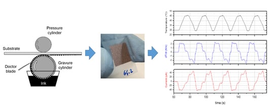
3.1. Overview on the Gravure Printable Pyroelectric Devices

Based on the operating principle of an elementary pyroelectric generator described above, the simplest configuration is a flat and parallel face capacitor [70], where a printed PVDF layer is stacked between two electrodes defining the active heat exchange area. The lower electrode forms the printing substrate. The upper electrode is subsequently placed on the top of the printed PVDF.
Printing requires the functional material to be deposited in solution form [38,71]. Mainly because of this, an important challenge is the control of the PVDF film-forming microstructure to achieve a significant level of polarization. In fact, as Equation (1) implies, the current depends strongly on the spontaneous polarization Ps of the pyroelectric material [5,18]. To meet this need, the kinetic conditionings over the physical processes involved in printing and/or the use of pre- or post-printing chemical-physical treatments require to be considered, as discussed below.
Among industrial printing techniques, gravure is the technique most used in the production of newspapers, magazines, currency and packaging, as it combines very high printing speed (over hundreds of meters per minute) with high resolution (down to 2 μm) and it is compatible with roll-to-roll processes [72,73,74,75,76,77]. This technique is characterized by the direct transfer of a low viscosity ink (1–100 mPa·s) from the micro-engraved cells of a chromium-plated cylinder to a substrate by means of the pressure of a counter-cylinder, as depicted in Figure 1 [78]. A doctor blade removes the excessive ink from the unengraved surfaces of the cylinder.
Despite its strengths, the low viscosity ink requirement represents a potential limit for gravure-printing-based devices because of the difficulty in achieving adequate film thickness. To address this issue, a multi-layered approach can be pursued [79,80].
Several physical parameters of the ink (e.g., viscosity, surface tension, solvent evaporation rate) and of the substrate (e.g., surface energy, porosity, smoothness), together with the process parameters (e.g., cells geometry and density, printing pressure, speed), contribute to determine the final quality of the printed film [38,75,78,81]. Preliminary printing tests are necessary for properly identifying the optimal operating windows of all the involved parameters, because of their interplay roles. [72].
The gravure printing process can be seen as a sequence of sub-processes (inking, doctoring, transfer, spreading, drying), each with its ideal operating regime controlling the final material arrangement in the printed layer [78]. Due to the complex multi-physical nature of this process, involving capillarity, viscoelasticity, inertia, gravity, moving contact lines and solvent evaporation changing ink composition, dimensional analysis can represent a useful tool for studying the physical system behavior [71,82,83]. At the microscopic level, the fluid dynamics of the gravure printing process are governed by the balance between viscous and surface tension forces, where the latter are the driving forces [71,84]. Consequently, the balance determines the printed pattern/shape morphology and fidelity [75]. At a particular printing speed (U), the capillary number Ca = ηU/γ (where η and γ are the viscosity and the surface tension of the ink respectively) can be used to describe the system during each stage of the process [39,52,78,84]. Typically, optimal printing can be achieved by tuning ink parameters and the print speed to attain a Ca ≈ 1 [75], but deviations could be considered to reach an optimal regime [71].

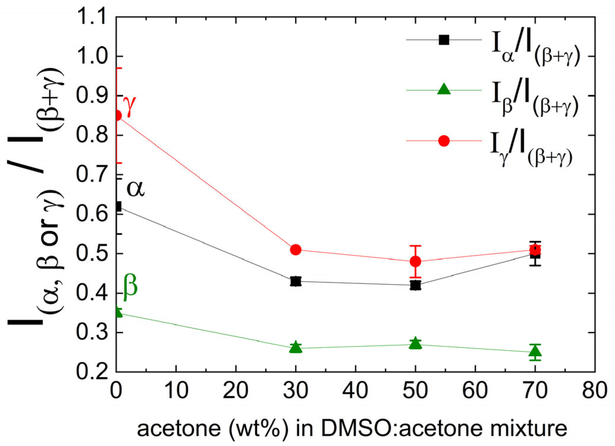
3.2. PVDF Ink Formulation

The first objective was to develop a PVDF-based gravure printable fluid (ink). To properly formulate a stable functional ink, different chemical-physical parameters, such as solubility, concentration, viscosity and surface tension need to be considered to ensure both the correct gravure printing processability and the specific characteristics for the functionality of the forming pyroelectric film.
First, the PVDF must be dissolved and appropriately diluted in a solvent to obtain a suitable viscosity [85,86,87]. Secondly, the ink concentration should be sufficiently high to obtain an adequate substrate coverage of the printed film, providing a dense polymer interconnection which is mainly responsible for the film transport properties [85]. However, the ink concentration needs to be properly adjusted, since it also contributes to determine the viscosity and the rheological behavior of the ink, together with the solvent–solvent and solvent–polymer interactions [78,88]. Moreover, the solvent also fulfills the important role of adjusting the ink surface tension on which the ink wettability depends [86]. In particular, to attain adequate wettability, the surface tension of the ink must be lower than the surface energy of the chromed engraved cylinder (42 mN/m) and of the printing substrate to favor the inking and transfer stages of the printing process [88,89]. Consequently, the quality of a printed film significantly depends on good substrate-ink interaction [52,90], however, this is only a prerequisite for obtaining good printing quality, since this is also strongly dependent on an appropriate choice of all the parameters involved in the gravure printing process. Finally, another fundamental parameter is the solvent evaporation rate, which controls the drying stage and determines the final morphology and microstructure of the solid film [78,86,89].
Therefore, obtaining the correct printing ink formulation is a complex task, involving several parameters, so that preliminary inking tests need to be conducted to identify the appropriate operating ranges to achieve the desired print quality. However, in the specific case of pyroelectric films, good printing quality is not sufficient to guarantee film functionality in a device, since it is essential that the printed film exhibits a significant level of spontaneous polarization.
From the above, the selection of the solvent is crucial for PVDF ink formulation. Due to their strong intermolecular interactions, few solvents can adequately dissolve the PVDF, or in a reasonable time [91]. Furthermore, once dissolved, PVDF tends to crystallize in its non-polar α phase, which is the most thermodynamically stable [58,59,87]. Nonetheless, the possibility of inducing phase transitions using high polar solvents has been observed [59,61,62,65,92,93]. In particular, N-methyl-2-pyrrolidone (NMP) and N, N-dimethylformamide (DMF) are the most used solvents, although they are expensive and have a high environmental impact [55,94,95,96,97].
To promote printing as an innovative and sustainable process for the production of low-cost and low environmental impact pyroelectric devices, dimethyl sulfoxide (DMSO) was chosen as the primary high polar solvent (dielectric constant, ε = 47), which favors the formation of β-PVDF as recently reported [59,62,87]. However, its high boiling point (189 °C) appears unsuitable for the rapid and low-cost gravure printing process, requiring high thermal powers for the complete drying of the printed film. Furthermore, high drying temperatures can favor PVDF crystallization in its non-polar α phase, which must be avoided for pyroelectric applications. Therefore, it was decided to use acetone as a co-solvent, since it is also a polar solvent (ε = 21), has low toxicity and a very low boiling point (56 °C) [97]. In addition, acetone has the further advantage of being able to decrease the surface tension of the PVDF-DMSO solution, as shown in Table S2. As expected, the acetone provokes a strong decrease in the ink surface tension, while the PVDF has a negligible effect in the investigated range of concentration. Such a decrease in the surface tension is essential for improving the PVDF ink printability [86].
After several preliminary dissolution and ink depositing tests simply using a wire-bar coating technique (see Appendix A), the 50/50% w/w of DMSO/acetone solution was selected as the best solvent for PVDF ink, because it showed the shortest PVDF dissolution time (1 h at 60 °C) and the best compromise between film drying time (30 min) and the development of PVDF polar phases, drying the ink film at a low temperature (50 °C). Such a low drying temperature was chosen because it has been reported that crystallization of the α phase is favored above 60 °C, becoming more and more predominant as the temperature increases [54,59,94]; moreover, exceeding 60 °C could deteriorate the PVDF film ferroelectric properties during multistep processes such as multilayer printing [26]. The structural characterization of the as-prepared PVDF film showed a high content of electroactive phases (see Figures S1 and S2 and Figure A1), satisfying the first requirement for possible PVDF pyroelectric functionality.

3.3. Tuning of the Gravure Printing Process of the PVDF Film

Low surface tension and viscosity characteristics are the basic requirements for an ink to be gravure printable and are fundamentally determined by the solvent system. Nonetheless, these properties do not by themselves ensure a good quality of final printed film, as this is also greatly dependent on the appropriate combination of all the other process parameters, such as the engraved cell geometry and density, the printing pressure and speed, and the drying conditions [39,78].
Therefore, several preliminary printing tests were carried out using PVDF inks diluted by 50/50% w/w of DMSO/acetone, varying the PVDF concentration (in a relevant range for gravure printing of 8 wt%–15 wt% of polymer), printing speed (12–60 m/min) and force (300–700 N), to investigate the optimal process parameters, namely, Ca values of about 1 (see Table S3). For such tests, the electronic engraving of the employed printing cylinder was used, having an inverted pyramidal cell geometry and a very high cell volume, to produce high substrate coverage and to maximize the ink film thickness. Once printed, the samples were dried in an oven at a temperature of 50 °C for 30 min. Once dried, inks with a PVDF solid content > 12 wt% exhibited poor print quality characterized by the presence of voids and defects, essentially due to the high viscosity of the ink (Ca ≈ 2), which did not allow optimal inking and ink transfer stages (see Figure S3a). Inks having a PVDF solid content ≤ 12 wt% produced films without macroscopic defects; using these inks, the best printing conditions in terms of resolution were found to be 500 N and 36 m/min (see Figure S3b).
To avoid the occurrence of possible micro-short circuits in the device, multilayer printing was performed to reach a PVDF film thickness of approximately 1 μm (see Table S4). The multilayer printing tests were executed by varying the concentration of the inks to be overlapped to mitigate surface roughness increase, as demonstrated elsewhere [79]. The high roughness caused by the multilayer deposition could limit the PVDF performance because of a non-optimal film/electrode interface. The best result (Sq of 0.10 ± 0.03 µm) was obtained by progressively printing five inks having decreasing concentrations of 12 wt%, 11 wt%, 10 wt%, 9 wt% and 8 wt% of PVDF, respectively, leaving unchanged the other process parameters, simplifying the overall printing process.
The final multilayer PVDF film was characterized by X-ray diffraction to analyze its crystalline phases (see Figure 2). As can be seen, there was a dominant broad signal centered at 2θ = 20.6°, mainly attributed to the presence of both β and γ phases; the shoulder on the left of this peak is given by the sum of the α and γ phase contributions [98]. The area under the substrate peak at 17.3 was also attributed to amorphous PVDF [99]. Furthermore, the observed broadening of the PVDF signal was due to the roughness of the printed samples [100] and/or to the small size of crystallites. The overlapping of the printed layers did not seem to alter the electroactive phases and α phase ratio. Therefore, the prepared multilayer showed high polar phases fractions (β and γ), which is the primary requirement for a possible pyroelectric response of PVDF printed film. Secondly, it was essential to have a high degree of dipole alignment in the film [8,10,18]—the larger this alignment is, the larger is the output of the generator [10]; in particular, the maximum condition for the capacitor is that its spontaneous polarization is orthogonal to the electrodes [70].
Controlling this alignment appears to be a particularly critical factor in solution-based printing processes, since these typically produce homogeneous polycrystalline films having, in general, random orientations of the crystalline domains, resulting in no macroscopic net polarization [45,46,47,48,101,102]. Consequently, the polycrystalline PVDF should be processed to orientate ideally all its crystalline domains to be normal to the substrate (electrode) for the pyroelectric application [2,45,70].
Therefore, as an alignment method compatible with the printing process, the corona pre-treatment of the substrate was considered. Corona treatment is currently the most used in-line process in the printing industry to modify the surface energy of a substrate, making it more wettable and therefore printable [103,104]. Corona treatment consists in producing a high-frequency electrical discharge able to break the surface molecular bonds of the substrate, creating free radicals able to form new surface functional groups [105]. Recently, it has been reported that, by depositing the PVDF from solution onto a hydrophilic substrate, it is possible to obtain self-polarization of the dipoles orthogonally to the substrate, through substrate-PVDF interaction via hydrogen bonds [51]. Since the corona discharge is performed in the air, the free radicals that superficially form on the substrate can interact and combine with oxygen and water atoms, resulting in hydrophilic polar functions [103,104].
To confirm this hypothesis, a contact angle characterization of corona-treated PET-ITO substrates was performed (see Figure 3). The treatment tests were conducted at a nominal power of 120 W; lower powers were not examined since they were found to be insufficient to provide adequate ITO wettability (see Figure S4), while no differences in the ink printability were observed by setting higher power values. Figure 3A shows the results of water and diiodomethane contact angle measurements and the surface energy values estimated for the treated substrates with increasing time. As can be seen, the contact angles strongly decreased with corona treatment time resulting in higher substrate hydrophilicity. This behavior was due to increase in the total surface energy of the substrates (Figure 3B). In particular, the polar component increased more than the dispersed component, suggesting a larger presence of the polar functions on the treated surface of the ITO [106,107]. Furthermore, the pre-treatment of the substrate increased the PVDF adhesion and did not appear to alter the crystallization of the PVDF in terms of amount and crystalline structure, as shown in Figure S5.
To evaluate the ferroelectric response of the as-prepared PVDF films, D-E hysteresis loops were also performed on some representative capacitor-like samples (see Figure 4). As can be seen, the multilayer printed PVDF showed large hysteresis loops indicating the presence of domains of spontaneously oriented polarization, namely a net remnant polarization moment. This result supports the hypothesis that the superficial hydrophilic groups of the corona-treated substrate can form hydrogen bonds with fluorine atoms of the PVDF triggering a layer-by-layer alignment mechanism across the multilayer [108,109].

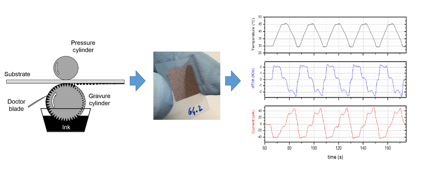
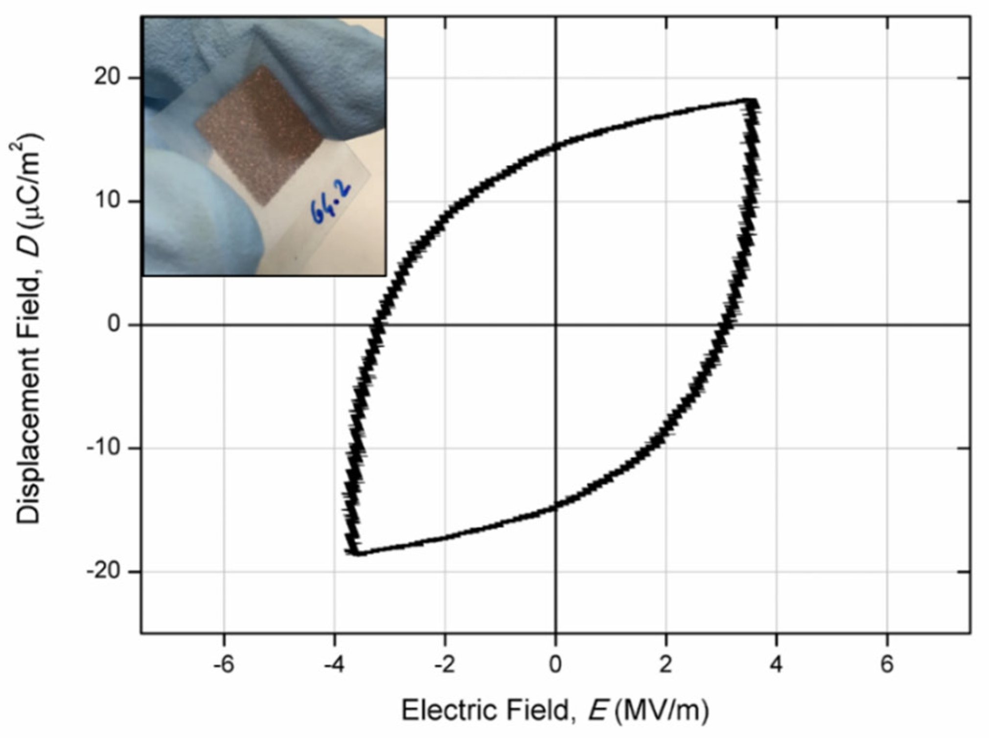
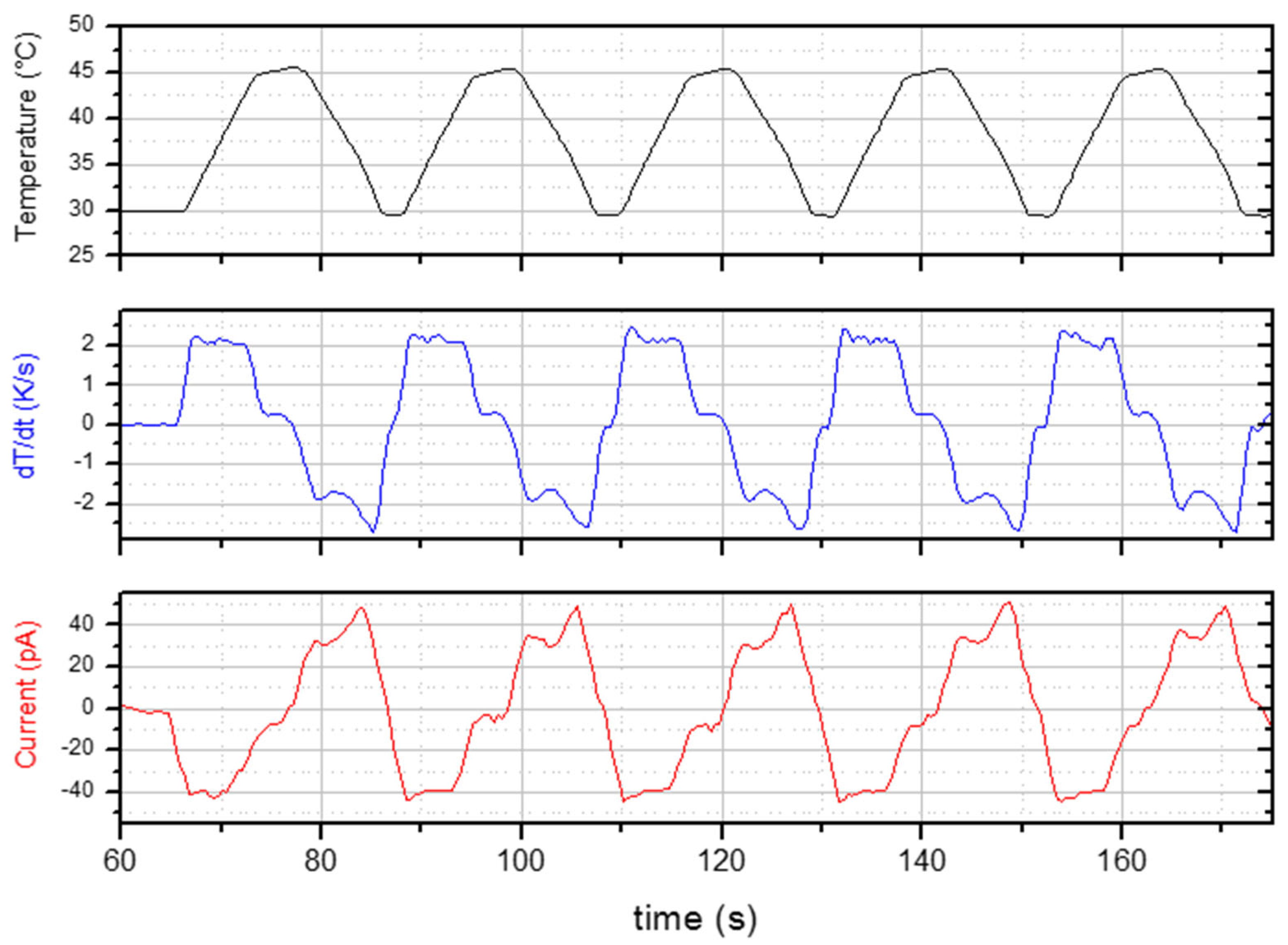
3.4. Functional Characterization of the Printed Devices

Finally, representative prepared capacitor devices were functionally characterized by imposing controlled thermal ramps at different nominal rates (0.8, 1.7, 2.1 and 2.5 K/s) between 30 and 45 °C setpoints and measuring the short-circuit current ip during the heating ramp (see Figure S6). Figure 5 shows an example of data acquisition, while in Table 1 the measured current and the pyroelectric coefficient p obtained by Equation (1) are reported. As can be seen, the obtained trends were compatible with pyroelectric phenomena: the measured electric current was proportional to the dT/dt profile and the time intervals of the null-measured electric current were identified and related to time intervals having constant temperature (null dT/dt). Moreover, the modulus of the pyroelectric current increased proportionally to the temperature rate. Such observations are expected from pyroelectric theory and appear coherent with the given model (Equation (1)). In addition, the pyroelectric characteristics appeared to increase as the corona pre-treatment time increased, confirming that the PVDF film self-poling mechanism, generated by the hydrophilic properties of the treated substrate, was able to vertically align the polymer dipoles.
The measured performances were lower than those reported for most of the pyroelectrics [19,70]. However, since, to date, there have been no examples of pyroelectric devices produced by gravure printing, there is the potential for further performance optimization.
Due to their novelty, the results obtained appear to be very significant from a technological point of view, and considering the high sustainability of the production processes, as well as for the potential to upscale the active area of the device and the production level.
Therefore, our results support the study of printed pyroelectric devices, especially considering the low expected thermal inertia and the favorable area scaling rules that characterize thin-film pyroelectric devices [15,19,23,24,30]. Highly scalable [52,110], and industrially widespread, large-area gravure printing [36,75] enables the deposition of high-quality layers at low cost, compensating for the possible performance limits of small deviceseven by connecting a large number of them.
There is the potential for further development to optimize the gravure printing process for production of pyroelectric devices and to improve the performance reported here. For example, opportunities include optimizing gravure cell geometry, reducing process times, assessing other poling methods compatible with printing, enhancing PVDF electroactive phase formation, using more performing PVDF co-polymers, and introducing ferroelectric nanofillers.

4. Conclusions

In this study, the application of highly scalable and industrially used gravure printing as an innovative and low-cost production method for the potential manufacture of pyroelectric devices was investigated. For the first time, due to a self-poling mechanism induced by corona pre-treatment of the printing substrate and to crystallization by low temperature polar solvent evaporation, multilayer gravure-printed PVDF thin-film pyroelectric devices have been successfully realized, without any poling post-processing step. Given the very low thermal inertia and surface-scaling performance expected for such devices, and the upscaling and customization potential of roll-to-roll gravure printing, the obtained results open new opportunities for the future development of flexible, cost-effective, on-demand pyroelectric devices and hybrid harvesters.

Supplementary Materials

The following supporting information can be downloaded at: https://www.mdpi.com/article/10.3390/coatings12071020/s1: Table S1: Raman bands assignment identified for the PVDF; Table S2: Results of surface tension measurements carried out on PVDF diluted in DMSO/Acetone solutions; Table S3: Preliminary printing tests results changing PVDF ink concentration, printing speed and force (ranking: ++ = Best quality/high resolution; + = Medium quality/acceptable resolution; - = Low quality/low resolution; X = Poor quality/layer defects). The printing results were the same for both Aluminum foil and PET-ITO substrates; Table S4: Layer characteristics of the gravure printed PVDF on Aluminum foil and PET-ITO substrates; Figure S1: Typical Raman spectrum of a PVDF film deposited on Aluminum foil by wire-bar coating; Figure S2: X-rays data of PVDF film obtained by depositing PVDF (15 wt%) dissolved in a mixture of 50/50 (%w/w) DMSO/acetone on Aluminum foil; Figure S3: Examples of preliminary printing tests on Aluminum foil: defects obtained using 15 wt% PVDF ink (a); high printing quality using 10 wt% PVDF ink (b); Figure S4: Example of gravure printed PVDF on PET-ITO substrate pre-treated by Corona at a power of 50 W; Figure S5: X-ray diffraction patterns (Cu Kα) of a gravure printed multilayer PVDF film (5 layers) on Aluminum foil: pristine (NT) and treated by corona at the nominal power of 120 W for 64 s (64); Figure S6: Temperature and electric current vs time for a multilayer PVDF device printed on a PET-ITO substrate treated by Corona at a nominal power of 120 W for 64 s.

Author Contributions

Conceptualization, G.S.; methodology, G.S., M.M., F.L., C.B. and R.M.; validation, G.S., M.M., F.L., C.B. and R.M.; investigation, G.S., M.M., F.L., C.B. and R.M.; resources, G.S.; data curation, G.S., M.M., F.L., C.B. and R.M.; writing—original draft preparation, G.S.; writing—review and editing, G.S., M.M., F.L., C.B. and R.M.; visualization, G.S., M.M., F.L., C.B. and R.M.; supervision, G.S. and M.M. All authors have read and agreed to the published version of the manuscript.

Funding

This work was supported by the Italian Ministry for Economic Development (MISE) through the projects “1.3 Materiali di frontiera per usi energetici” (CUP: I34I19005780001) within the Three-Year Plan 2019–2021 of the National Electric System Research Fund.

Institutional Review Board Statement

Not applicable.

Informed Consent Statement

Not applicable.

Data Availability Statement

The raw data can be obtained from the corresponding authors upon reasonable request.

Conflicts of Interest

The authors declare no conflict of interest.

Appendix A

Preliminary tests were carried out to verify PVDF (10 wt%–20 wt%) dissolution in the DMSO. Up to 60 °C, the dissolution of the PVDF was observed over a relatively long time (about 4 h); higher temperatures resulted in more rapid dissolution but also a yellowing of the solutions and, consequently, have not been used. Acetone was used as a co-solvent to reduce the PVDF dissolution time and to adjust the surface tension (see Table S2) and drying rate of the PVDF ink. Once the PVDF concentration (15 wt%) was fixed, different mixtures were tested to determine the optimal DMSO/acetone ratio (%w/w), in terms of dissolution and drying times, and PVDF electroactive phase development of the deposited ink film. The solutions with low acetone quantities (<50 wt%) showed long dissolution times, similar to pure DMSO; the shortest dissolution time (1h) was obtained using a 50/50% w/w solution of DMSO/acetone.
The prepared solutions (viscosity of 68 mPa·s at 25 °C) were deposited on an aluminum foil via a wire-bar coater to evaluate the morphological characteristics and the crystallization of the PVDF films. For the deposition, a standard green k bar (wire diameter of 0.31 mm, depth of 24 µm) was used. Macroscopically, no differences were observed in applying the different solutions, which appeared uniform and eye-defects free. The deposited films were then dried in an oven at 50 °C for one hour before characterization.
Figure S1 shows a typical Raman spectrum of a prepared PVDF film measured in the region 300–1400 cm−1. The assignments of the bands to the specific vibrations in the polymer chain are reported in Table S1. As most researchers attribute the bands at 514 cm−1 to the β, 799 cm−1 to the α, 812 cm−1 to the γ and 840 cm−1 to both the β and γ phases, respectively, only these bands were considered in this study [65,66,67,68,69]. To estimate the relative content of each phase in the prepared films due to the presence of acetone, the intensity of the most representative peaks of each phase (α, β, γ) was related to the band generally attributed to the β and/or γ phase in the sample (see Figure A1). The intensity ratios Iα/I(β+γ) and Iγ/I(β+γ) quickly decreased by increasing the acetone concentration while the Iβ/I(β+γ) was about constant. Although the use of a low polar and boiling solvent may favor the α phase, the results do not seem to confirm such a hypothesis. In fact, the final effect of the solvent mixture on PDVF polymorph behavior was complex and influenced by several parameters: the solvent polarity, the evaporation rate, and the post-deposition annealing conditions [87].
Therefore, the 50/50% w/w DMSO/acetone solution was selected as the optimal mixed solvent ratio for making PVDF printing inks, because it showed the shortest PVDF dissolution time (1 h) and the best compromise between the film drying time (30 min) and the development of PVDF polar phases drying at 50 °C. In fact, using more DMSO than 50 wt%, the complete drying of the PVDF films at 50 °C was very slow (up to 2h in the case of pure DMSO), due to its high boiling temperature (189 °C). Conversely, using more than 50 wt% of acetone, the film drying time was greatly reduced, due to the low boiling point of acetone (56 °C), but favoring the growth of the α phase (see Figure A1).
To confirm the crystalline phases of the PVDF, the film prepared using 50/50% w/w DMSO/acetone solution was also characterized by X-ray diffraction, as reported in Figure S2. The diffractogram confirmed a high fraction of electroactive PVDF in the prepared samples, showing a dominant peak at 2θ = 20.4°, which was mainly attributed to the γ and β phases [54,98]. Indeed, the γ phase had a higher peak at 20.3° and two lower peaks at about 18.5° and 39°, while the β phase diffraction peaks were at 20.6 and 36.3° [98]. The shoulder was due to both the γ and α phases; the α phase was characterized by three peaks at about 2θ = 17.7°, 18.6° and 19.9° and a weak peak at about 35.9° [54]. Furthermore, the substrate signals were present at 17.2° and 44.8°.
Figure A1. Intensity ratios of the bands centered at 799 cm−1 (form α), 514 cm−1 (form β), and 812 cm−1 (form γ), with the band at 840 cm−1 (attributed to polar forms β and γ), measured for PVDF films produced by wire-bar coating, using inks with different DMSO/acetone ratio.
Coatings 12 01020 g0a1

References

  1. Karim, H.; Sarker, M.R.; Shahriar, S.; Shuvo, M.A.I.; Delfin, D.; Hodges, D.; Tseng, T.-L.; Roberson, D.; Love, N.; Lin, Y. Feasibility study of thermal energy harvesting using lead free pyroelectrics. Smart Mater. Struct. 2016, 25, 055022. [Google Scholar] [CrossRef]
  2. Wan, C.; Bowen, C.R. Multiscale-structuring of polyvinylidene fluoride for energy harvesting: The impact of molecular-, micro- and macro-structure. J. Mater. Chem. A 2017, 5, 3091–3128. [Google Scholar] [CrossRef] [Green Version]
  3. Zhang, Z.; Hanrahan, B.; Shi, C.; Khaligh, A. Management and storage of energy converted via a pyroelectric heat engine. Appl. Energy 2018, 230, 1326–1331. [Google Scholar] [CrossRef]
  4. Thakur, P.; Kool, A.; Hoque, N.A.; Bagchi, B.; Khatun, F.; Biswas, P.; Brahma, D.; Roy, S.; Banerjee, S.; Das, S. Superior performances of in situ synthesized ZnO/PVDF thin film based self-poled piezoelectric nanogenerator and self-charged photo-power bank with high durability. Nano Energy 2018, 44, 456–467. [Google Scholar] [CrossRef]
  5. Hsiao, C.-C.; Siao, A.-S.; Tsai, Y.-J. A strategy for optimal energy conversion by pyroelectricity. Int. J. Green Energy 2018, 15, 780–788. [Google Scholar] [CrossRef]
  6. Khan, A.A.; Mahmud, A.; Ban, D. Evolution from single to hybrid nanogenerator: A contemporary review on multimode energy harvesting for self-powered electronics. IEEE Trans. Nanotechnol. 2019, 18, 21–36. [Google Scholar] [CrossRef]
  7. Bai, Y.; Jantunen, H.; Juuti, J. Energy harvesting research: The road from single source to multisource. Adv. Mater. 2018, 30, 1707271. [Google Scholar] [CrossRef] [Green Version]
  8. Costa, P.; Nunes-Pereira, J.; Pereira, N.; Castro, N.; Goncalves, S.; Lanceros-Mendez, S. Recent progress on piezoelectric, pyroelectric, and magnetoelectric polymer-based energy-harvesting devices. Energy Technol. 2019, 7, 1800852. [Google Scholar] [CrossRef]
  9. Ko, Y.J.; Yun, B.K.; Jung, J.H. A 0.7Pb(Mg1/3Nb2/3)O3-0.3PbTiO3-based pyroelectric generator and temperature sensor. J. Korean Phys. Soc. 2015, 66, 713–716. [Google Scholar] [CrossRef]
  10. Kim, J.; Lee, J.H.; Ryu, H.; Lee, J.-H.; Khan, U.; Kim, H.; Kwak, S.S.; Kim, S.-W. High-performance piezoelectric, pyroelectric, and, triboelectric nanogenerators based on P(VDF-TrFE) with controlled crystallinity and dipole alignment. Adv. Funct. Mater. 2017, 27, 1700702. [Google Scholar] [CrossRef]
  11. Zabek, D.; Seunarine, K.; Spacie, C.; Bowen, C. Graphene ink laminate structures on Poly(vinylidene difluoride) (PVDF) for pyroelectric thermal energy harvesting and waste heat recovery. ACS Appl. Mater. Interfaces 2017, 9, 9161–9167. [Google Scholar] [CrossRef] [PubMed] [Green Version]
  12. Beasley, A.E.; Bowen, C.R.; Zabek, D.A.; Clarke, C.T. Use it or lose it: The influence of second order effects of practical components on storing energy harvested by pyroelectric effects. Tm-Tech. Mess. 2018, 85, 533–540. [Google Scholar] [CrossRef]
  13. Ravindran, S.K.T.; Huesgen, T.; Kroener, M.; Woias, P. A self-sustaining micro thermomechanic-pyroelectric generator. Appl. Phys. Lett. 2011, 99, 104102. [Google Scholar] [CrossRef]
  14. Hsiao, C.-C.; Huang, S.-W.; Chang, R.-C. Temperature field analysis for ZnO thin-film pyroelectric devices with partially covered electrode. Sens. Mater. 2012, 24, 421–441. [Google Scholar]
  15. Lingam, D.; Parikh, A.R.; Huang, J.; Jain, A.; Minary-Jolandan, M. Nano/microscale pyroelectric energy harvesting: Challenges and opportunities. Int. J. Smart Nano Mater. 2013, 4, 229–245. [Google Scholar] [CrossRef] [Green Version]
  16. Lee, S.; Singh, N.; Phelan, P.E.; Wu, C.-J. Harvesting CPU Waste Heat Through Pyroelectric Materials. In Proceedings of the ASME 2015 International Technical Conference and Exhibition on Packaging and Integration of Electronic and Photonic Microsystems, San Francisco, CA, USA, 6–9 July 2015; pp. 1–9. [Google Scholar]
  17. Zabek, D.; Morini, F. Solid state generators and energy harvesters for waste heat recovery and thermal energy harvesting. Therm. Sci. Eng. Prog. 2019, 9, 235–247. [Google Scholar] [CrossRef]
  18. Thakre, A.; Kumar, A.; Song, H.-C.; Jeong, D.-Y.; Ryu, J. Pyroelectric energy conversion and its applications-flexible energy harvesters and sensors. Sensors 2019, 19, 2170. [Google Scholar] [CrossRef] [Green Version]
  19. Bowen, C.R.; Taylor, J.; LeBoulbar, E.; Zabek, D.; Chauhan, A.; Vaish, R. Pyroelectric materials and devices for energy harvesting applications. Energy Environ. Sci. 2014, 7, 3836–3856. [Google Scholar] [CrossRef] [Green Version]
  20. Xie, M.; Zabek, D.; Bowen, C.; Abdelmageed, M.; Arafa, M. Wind-driven pyroelectric energy harvesting device. Smart Mater. Struct. 2016, 25, 125023. [Google Scholar] [CrossRef] [Green Version]
  21. Zhang, H.; Xie, Y.; Li, X.; Huang, Z.; Zhang, S.; Su, Y.; Wu, B.; He, L.; Yang, W.; Lin, Y. Flexible pyroelectric generators for scavenging ambient thermal energy and as self-powered thermosensors. Energy 2016, 101, 202–210. [Google Scholar] [CrossRef]
  22. Chen, Y.; Zhang, Y.; Yuan, F.; Ding, F.; Schmidt, O.G. A flexible PMN-PT ribbon-based piezoelectric-pyroelectric hybrid generator for human-activity energy harvesting and monitoring. Adv. Electron. Mater. 2017, 3, 1600540. [Google Scholar] [CrossRef] [Green Version]
  23. Pandya, S.; Velarde, G.; Zhang, L.; Wilbur, J.D.; Smith, A.; Hanrahan, B.; Dames, C.; Martin, L.W. New approach to waste-heat energy harvesting: Pyroelectric energy conversion. NPG Asia Mater. 2019, 11, 1–26. [Google Scholar] [CrossRef]
  24. Zabek, D.; Taylor, J.; Bowen, C.R. Performance of Thin Film Polyvinylidenefluoride (PVDF) for Pyroelectric Energy Harvesting. In Proceedings of the Joint IEEE International Symposium on the Applications of Ferroelectric, State College, PA, USA, 12–16 May 2014; pp. 1–4. [Google Scholar]
  25. Kishore, R.A.; Priya, S. A review on low-grade thermal energy harvesting: Materials, methods and devices. Materials 2018, 11, 1433. [Google Scholar] [CrossRef] [PubMed] [Green Version]
  26. Zabek, D.; Taylor, J.; Le Boulbar, E.; Bowen, C.R. Micropatterning of flexible and free standing polyvinylidene difluoride (PVDF) films for enhanced pyroelectric energy transformation. Adv. Energy Mater. 2015, 5, 1401891. [Google Scholar] [CrossRef] [Green Version]
  27. Bowen, C.R.; Xie, M.; Zhang, Y.; Topolov, V.Y.; Wan, C. Pyroelectric Energy Harvesting: Materials and Applications. In Ferroelectric Materials for Energy Applications; Huang, H., Scott, J.F., Eds.; Wiley-VCH Verlag GmbH &Co. KGaA: Weinheim, Germany, 2018; pp. 203–230. [Google Scholar]
  28. Sultana, A.; Alam, M.M.; Middya, T.R.; Mandal, D. A pyroelectric generator as a self-powered temperature sensor for sustainable thermal energy harvesting from waste heat and human body. Appl. Energy 2018, 221, 299–307. [Google Scholar] [CrossRef]
  29. He, H.; Lu, X.; Hanc, E.; Chen, C.; Zhang, H.; Lu, L. Advances in lead-free pyroelectric materials: A comprehensive review. J. Mater. Chem. C 2020, 8, 1494–1516. [Google Scholar] [CrossRef]
  30. Poprawski, W.; Gnutek, Z.; Radojewski, J.; Poprawski, R. Pyroelectric and dielectric energy conversion–a new view of the old problem. Appl. Therm. Eng. 2015, 90, 858–868. [Google Scholar] [CrossRef]
  31. Jankowski, N.R.; Smith, A.N.; Hanrahan, B.M. Thermal model of a thin film pulsed pyroelectric generator. In Proceedings of the ASME 2016 Heat Transfer Summer Conference, Washington, DC, USA, 10–14 July 2016. [Google Scholar]
  32. Yang, Y.; Guo, W.; Pradel, K.C.; Zhu, G.; Zhou, Y.; Zhang, Y.; Hu, Y.; Lin, L.; Wang, Z.L. Pyroelectric nanogenerator for harvesting thermoelectric energy. Nano Lett. 2012, 12, 2833–2838. [Google Scholar] [CrossRef]
  33. Dorey, R.A. Integrated Powder-Based Thick Films for Thermoelectric, Pyroelectric, and Piezoelectric Energy Harvesting Devices. IEEE Sens. J. 2014, 14, 2177–2184. [Google Scholar] [CrossRef] [Green Version]
  34. Ji, Y.; Wang, Y.; Yang, Y. Photovoltaic–Pyroelectric–Piezoelectric Coupled Effect Induced Electricity for Self-Powered Coupled Sensing. Adv. Electron. Mater. 2019, 5, 1900195. [Google Scholar] [CrossRef]
  35. Bevione, M.; Garofalo, E.; Cecchini, L.; Chiolerio, A. Liquid-state pyroelectric energy harvesting. MRS Energy Sustain. 2020, 7, 38. [Google Scholar] [CrossRef]
  36. Wu, W. Inorganic nanomaterials for printed electronics: A review. Nanoscale 2017, 9, 7342–7372. [Google Scholar] [CrossRef] [PubMed]
  37. Abbel, R.; Galagan, Y.; Groen, P. Roll-to-Roll Fabrication of Solution Processed Electronics. Adv. Eng. Mater. 2018, 20, 1701190–1701219. [Google Scholar] [CrossRef] [Green Version]
  38. Khan, S.; Lorenzelli, L.; Dahiya, R.S. Technologies for printing sensors and electronics over large flexible substrates: A review. IEEE Sens. J. 2014, 15, 3164–3185. [Google Scholar] [CrossRef]
  39. Arrabito, G.; Aleeva, Y.; Pezzilli, R.; Ferrara, V.; Medaglia, P.G.; Pignataro, B.; Prestopino, G. Printing ZnO Inks: From Principles to Devices. Crystals 2020, 10, 449. [Google Scholar] [CrossRef]
  40. Bodkhe, S.; Rajesh, P.S.M.; Gosselin, F.P.; Therriault, D. Simultaneous 3D printing and poling of PVDF and its nanocomposites. ACS Appl. Energy Mater. 2018, 1, 2474–2482. [Google Scholar] [CrossRef]
  41. Takamatsu, K.; Kobayashi, N.; Tsujimura, T.; Matsumoto, K.; Takada, K.; Ichimura, H. Ceramic Films of Pb4.95Ba0.05Ge3O11 by Printing Technique and Their Pyroelectric Characteristics. Jpn. J. Appl. Phys. 1985, 24, 175. [Google Scholar] [CrossRef] [Green Version]
  42. Futakuchi, T.; Tanino, K. Pyroelectric Properties of La-Modified PbTiO3 Thin Films Prepared by Screen Printing. Jpn. J. Appl. Phys. 1994, 33, 5294. [Google Scholar] [CrossRef]
  43. Menil, F.; Debeda, H.; Lucat, C. Screen-printed thick-films: From materials to functional devices. J. Eur. Ceram. Soc. 2005, 25, 2105–2113. [Google Scholar] [CrossRef]
  44. Noh, H.-J.; Lee, S.-G.; Nam, S.-P. Dielectric and Pyroelectric Properties of Dy-doped BSCT Thick Films by Screen-printing Method. J. Electr. Eng. Technol. 2009, 4, 527–530. [Google Scholar] [CrossRef] [Green Version]
  45. Dorey, R. Microstructure–property relationships: How the microstructure of the film affects its properties. In Ceramic Thick Films for MEMS and Microdevices; Andrew, W., Ed.; Elsevier: Waltham, MA, USA, 2012; pp. 85–112. [Google Scholar]
  46. Wang, H.; Xu, Y.; Yu, X.; Xing, R.; Liu, J.; Han, Y. Structure and morphology control in thin films of conjugated polymers for an improved charge transport. Polymers 2013, 5, 1272–1324. [Google Scholar] [CrossRef] [Green Version]
  47. Diao, Y.; Shaw, L.; Bao, Z.; Mannsfeld, S.C.B. Morphology control strategies for solution-processed organic semiconductor thin films. Energy Environ. Sci. 2014, 7, 2145–2159. [Google Scholar] [CrossRef] [Green Version]
  48. Diao, Y.; Zhou, Y.; Kurosawa, T.; Shaw, L.; Wang, C.; Park, S.; Guo, Y.; Reinspach, J.A.; Gu, K.; Gu, X.; et al. Flow-enhanced solution printing of all-polymer solar cells. Nat. Commun. 2015, 6, 1–10. [Google Scholar] [CrossRef] [PubMed] [Green Version]
  49. Søndergaard, R.R.; Hösel, M.; Krebs, F.C. Roll-to-Roll fabrication of large area functional organic materials. J. Polym. Sci. Part. B Polym. Phys. 2013, 51, 16–34. [Google Scholar] [CrossRef]
  50. Krebs, F.C. Fabrication and processing of polymer solar cells: A review of printing and coating techniques. Sol. Energy Mater. Sol. Cells 2009, 93, 394–412. [Google Scholar] [CrossRef]
  51. Wu, C.-M.; Chou, M.-H.; Chala, T.F.; Shimamura, Y.; Murakami, R.-I. Infrared-driven poly(vinylidene difluoride)/tungsten oxide pyroelectric generator for non-contact energy harvesting. Compos. Sci. Technol. 2019, 178, 26–32. [Google Scholar] [CrossRef]
  52. Liang, J.; Jiang, C.; Wu, W. Printed flexible supercapacitor: Ink formulation, printable electrode materials and applications. Appl. Phys. Rev. 2021, 8, 021319. [Google Scholar] [CrossRef]
  53. Jiang, Y.; Ye, Y.; Yu, J.; Wu, Z.; Li, W.; Xu, J.; Xie, G. Study of thermally poled and corona charged poly(vinylidene fluoride) films. Polym. Eng. Sci. 2007, 47, 1344–1350. [Google Scholar] [CrossRef]
  54. Mahadeva, S.K.; Berring, J.; Walus, K.; Stoeber, B. Effect of poling time and grid voltage on phase transition and piezoelectricity of poly (vinylidene fluoride) thin films using corona poling. J. Phys. D Appl. Phys. 2013, 46, 285305. [Google Scholar] [CrossRef]
  55. Shaik, H.; Rachith, S.N.; Rudresh, K.J.; Sheik, A.S.; Raman, K.H.T.; Kondaiah, P.; Rao, G.M. Towards β-phase formation probability in spin coated PVDF thin films. J. Polym. Res. 2017, 24, 1–6. [Google Scholar] [CrossRef]
  56. Tan, K.S.; Gan, W.C.; Velayutham, T.S.; Abd Majid, W.H. Pyroelectricity enhancement of PVDF nanocomposites thin films doped with ZnO nanoparticles. Smart Mater. Struct. 2014, 23, 125006. [Google Scholar] [CrossRef]
  57. Martins, P.; Lopes, A.C.; Lanceros-Mendez, S. Electroactive phases of poly(vinylidene fluoride): Determination, processing and applications. Prog. Polym. Sci. 2014, 39, 683–706. [Google Scholar] [CrossRef]
  58. Wang, F.; Zhao, X.; Li, J. PVDF energy-harvesting devices: Film preparation, electric poling, energy-harvesting efficiency. In Proceedings of the IEEE Conference on Electrical Insulation and Dielectric Phenomena (CEIDP), Ann Arbor, MI, USA, 18–21 October 2015; pp. 80–83. [Google Scholar]
  59. Li, X.; Wang, Y.; He, T.; Hu, Q.; Yang, Y. Preparation of PVDF flexible piezoelectric film with high β-phase content by matching solvent dipole moment and crystallization temperature. J. Mater. Sci. Mater. Electron. 2019, 30, 20174–20180. [Google Scholar] [CrossRef]
  60. Tu, R.; Sprague, E.; Sodano, H.A. Precipitation-printed high-β phase Poly(vinylidene fluoride) for energy harvesting. ACS Appl. Mater. Interfaces 2020, 12, 58072–58081. [Google Scholar]
  61. Tansel, T. High beta-phase processing of polyvinylidenefluoride for pyroelectric applications. J. Polym. Res. 2020, 27, 95. [Google Scholar] [CrossRef]
  62. Ruan, L.; Yao, X.; Chang, Y.; Zhou, L.; Qin, G.; Zhang, X. Properties and applications of the β phase Poly(vinylidene fluoride). Polymers 2018, 10, 228. [Google Scholar] [CrossRef] [Green Version]
  63. Li, Y.; Ma, X.; Ding, Y.; Li, X.; Li, Z. Density Functional Theory Simulation of PVDF Transition in Electric Field Polarization. In Proceedings of the International Conference on Mathematics, Modeling and Simulation Technologies and Applications, Xiamen, China, 27–28 October 2019. [Google Scholar]
  64. Guo, X.; Wang, J.; Ding, J.; Jiang, Y. Study on preparation and polarization process of PVDF thin film. In Proceedings of the International Symposium on Advanced Optical Manufacturing and Testing Technologies, Harbin, China, 26–29 April 2014; p. 92841F-7. [Google Scholar]
  65. Satapathy, S.; Pawar, S.; Gupta, P.K.; Varma, K.B.R. Effect of annealing on phase transition in poly(vinylidene fluoride) films prepared using polar solvent. Bull. Mater. Sci. 2011, 34, 727–733. [Google Scholar] [CrossRef] [Green Version]
  66. Ma, J.; Zhang, Q.; Lin, K.; Zhou, L.; Ni, Z. Piezoelectric and optoelectronic properties of electrospinning hybrid PVDF and ZnO nanofibers. Mater. Res. Express 2018, 5, 035057. [Google Scholar] [CrossRef]
  67. Elashmawi, I.S.; Gaabour, L.H. Raman, morphology and electrical behavior of nanocomposites based on PEO/PVDF with multi-walled carbon nanotubes. Results Phys. 2015, 5, 105–110. [Google Scholar] [CrossRef] [Green Version]
  68. Barnakov, Y.A.; Paul, O.; Joaquim, A.; Falconer, A.; Mu, R.; Barnakov, V.Y.; Dikin, D.; Petranovskii, V.P.; Zavalin, A.; Ueda, A.; et al. Light intensity-induced phase transitions in Graphene oxide doped polyvinylidene fluoride. Opt. Mater. Express 2018, 8, 2579–2585. [Google Scholar] [CrossRef]
  69. Constantino, C.J.L.; Job, A.E.; Simoes, R.D.; Giacometti, J.A.; Zucolotto, V.; Oliveira, O.N.; Gozzi, G.; Chinaglia, D.L. Phase Transition in Poly(vinylidene fluoride) Investigated with Micro-Raman Spectroscopy. Appl. Spectrosc. 2005, 59, 275–279. [Google Scholar] [CrossRef] [PubMed]
  70. Ryu, H.; Kim, S.-W. Emerging pyroelectric nanogenerators to convert thermal energy into electrical energy. Small 2021, 17, 1903469. [Google Scholar] [CrossRef] [PubMed]
  71. Grau, G.; Cen, J.; Kang, H.; Kitsomboonloha, R.; Scheideler, W.J.; Subramanian, V. Gravure-printed electronics: Recent progress in tooling development, understanding of printing physics, and realization of printed devices. Flex. Print. Electron. 2016, 1, 1–23. [Google Scholar] [CrossRef]
  72. Lee, J.A.; Rothstein, J.P.; Pasquali, M. Computational study of viscoelastic effects on liquid transfer during gravure printing. J. Non-Newton. Fluid Mech. 2013, 199, 1–11. [Google Scholar] [CrossRef]
  73. Grau, G.; Kitsomboonloha, R.; Subramanian, V. Fabrication of a high-resolution roll for gravure printing of 2μm features. In Proceedings of the SPIE Organic Photonics + Electronics, San Diego, CA, USA, 9–13 August 2015. [Google Scholar]
  74. Grau, G.; Subramanian, V. Fully High-Speed Gravure Printed, Low-Variability, High-Performance Organic Polymer Transistors with Sub-5 V Operation. Adv. Electron. Mater. 2016, 2, 1500328. [Google Scholar] [CrossRef]
  75. Huang, Q.; Zhu, Y. Printing conductive nanomaterials for flexible and stretchable electronics: A review of materials, processes, and applications. Adv. Mater. Technol. 2019, 4, 1800546. [Google Scholar] [CrossRef]
  76. Bonnassieux, Y.; Brabec, C.J.; Cao, Y.; Breen Carmichael, T.; Chabinyc, M.L.; Cheng, K.-T.; Cho, G.; Chung, A.; Cobb, C.L.; Distler, A.; et al. The 2021 flexible and printed electronics roadmap. Flex. Print. Electron. 2021, 6, 023001. [Google Scholar] [CrossRef]
  77. Tiara, A.M.; Moon, H.; Cho, G.; Lee, J. Fully roll-to-roll gravure printed electronics: Challenges and the way to integrating logic gates. Jpn. J. Appl. Phys. 2022, 61, SE0802. [Google Scholar]
  78. Sico, G.; Montanino, M.; Prontera, C.T.; De Girolamo Del Mauro, A.; Minarini, C. Gravure printing for thin film ceramics manufacturing from nanoparticles. Ceram. Int. 2018, 44, 19526–19534. [Google Scholar] [CrossRef]
  79. Sico, G.; Montanino, M.; De Girolamo Del Mauro, A.; Imparato, A.; Nobile, G.; Minarini, C. Effects of the ink concentration on multi-layer gravure-printed PEDOT:PSS. Org. Electron. 2016, 28, 257–262. [Google Scholar] [CrossRef]
  80. Montanino, M.; Sico, G.; De Girolamo Del Mauro, A.; Asenbauer, J.; Binder, J.R.; Bresser, D.; Passerini, S. Gravure-Printed Conversion/Alloying Anodes for Lithium-Ion Batteries. Energy Technol. 2021, 9, 2100315. [Google Scholar] [CrossRef]
  81. Choi, Y.; Kim, G.H.; Jeong, W.H.; Kim, H.J.; Chin, B.D.; Yu, J.-W. Characteristics of gravure printed InGaZnO thin films as an active channel layer in thin film transistors. Thin Solid Film. 2010, 518, 6249–6252. [Google Scholar] [CrossRef]
  82. Khandavalli, S.; Rothstein, J.P. Ink transfer of non-Newtonian fluids from an idealized gravure cell: The effect of shear and extensional deformation. J. Non-Newton. Fluid Mech. 2017, 243, 16–26. [Google Scholar] [CrossRef]
  83. Pingulkar, H.; Peixinho, J.; Crumeyrolle, O. Liquid transfer for viscoelastic solutions. Langmuir 2021, 37, 10348–10353. [Google Scholar] [CrossRef] [PubMed]
  84. Sankaran, A.K.; Rothstein, J.P. Effect of viscoelasticity on liquid transfer during gravure printing. J. Non-Newton. Fluid Mech. 2012, 175, 64–75. [Google Scholar] [CrossRef]
  85. Jo, S.; Choo, S.; Kim, F.; Heo, S.H.; Son, J.S. Ink processing for thermoelectric materials and power-generating devices. Adv. Mater. 2018, 31, 1804930. [Google Scholar] [CrossRef] [PubMed]
  86. Schlisske, S.; Rosenauer, C.; Rödlmeier, T.; Giringer, K.; Michels, J.J.; Kremer, K.; Lemmer, U.; Morsbach, S.; Daoulas, K.C.; Hernandez-Sosa, G. Ink Formulation for Printed Organic Electronics: Investigating Effects of Aggregation on Structure and Rheology of Functional Inks Based on Conjugated Polymers in Mixed Solvents. Adv. Mater. Technol. 2020, 6, 2000335. [Google Scholar] [CrossRef]
  87. Marshall, J.E.; Zhenova, A.; Roberts, S.; Petchey, T.; Zhu, P.; Dancer, C.E.J.; McElroy, C.R.; Kendrick, E.; Goodship, V. On the solubility and stability of Polyvinylidene Fluoride. Polymers 2021, 13, 1354. [Google Scholar] [CrossRef]
  88. Glasser, A.; Cloutet, E.; Hadziioannou, G.; Kellay, H. Tuning the rheology of conductiong polymer inks for various deposition processes. Chem. Mater. 2019, 31, 6936–6944. [Google Scholar] [CrossRef]
  89. Chang, Q.; Cao, C.; Qiao, H.; Hu, Y.; Xiao, G.; Shi, W. Ink transfer for printed flexible microsupercapacitors. Carbon 2021, 178, 285–293. [Google Scholar] [CrossRef]
  90. Kamarudin, M.A.; Sahamir, S.R.; Datta, R.S.; Long, B.D.; Sabri, M.F.M.; Said, S.M. A review on fabrication of polymer-based thermoelectric materials and fabrication methods. Sci. World J. 2013, 2013, 1–17. [Google Scholar] [CrossRef] [PubMed] [Green Version]
  91. Bottino, A.; Capannelli, G.; Munari, S.; Turturro, A. Solubility parameters of poly(vinylidene fluoride). J. Polym. Sci. Part B Polym. Phys. 1988, 26, 785–794. [Google Scholar] [CrossRef]
  92. Jee, T.; Lee, H.; Mika, B.; Liang, H. Effect of microstructures of PVDF on surface adhesive forces. Tribol. Lett. 2007, 26, 125–130. [Google Scholar] [CrossRef]
  93. Mai, M.; Fridkin, V.; Martin, B.; Leschhorn, A.; Kliem, H. The thickness dependence of the phase transition temperature in PVDF. Phys. B 2013, 421, 23–27. [Google Scholar] [CrossRef]
  94. Gregorio, R. Determination of the α, β, and γ crystalline phases of Poly(vinylidene fluoride) films prepared at different conditions. J. Appl. Polym. Sci. 2006, 100, 3272–3279. [Google Scholar] [CrossRef]
  95. Harstad, S.; D’Souza, N.; Soin, N.; El-Gendy, A.A.; Gupta, S.; Pecharsky, V.K.; Shah, T.; Siores, E.; Hadimani, R.L. Enhancement of β-phase in PVDF films embedded with ferromagnetic Gd5Si4 nanoparticles for piezoelectric energy harvesting. AIP Adv. 2017, 7, 056411. [Google Scholar] [CrossRef]
  96. Mahale, B.; Bodas, D.; Gangal, S.A. Study of β-phase development in spin-coated PVDF thick film. Bull. Mater. Sci. 2017, 40, 569–575. [Google Scholar] [CrossRef]
  97. Joshi, D.R.; Adhikari, N. An Overview on Common Organic Solvents and Their Toxicity. J. Pharm. Res. Int. 2019, 28, 1–18. [Google Scholar] [CrossRef]
  98. Cai, X.; Lei, T.; Sund, D.; Lind, L. A critical analysis of the α, β and γ phases in poly(vinylidene fluoride) using FTIR. RSC Adv. 2017, 7, 15382–15389. [Google Scholar] [CrossRef] [Green Version]
  99. Wu, L.; Jin, Z.; Liu, Y.; Ning, H.; Liu, X.; Alamusi; Hu, N. Recent advances in the preparation of PVDF-based piezoelectric materials. Nanotechnol. Rev. 2022, 11, 1386–1407. [Google Scholar] [CrossRef]
  100. Payne, A.P.; Clemens, B.M. Influence of roughness distributions and correlations on x-ray diffraction from superlattices. Phys. Rev. B 1993, 47, 2289. [Google Scholar] [CrossRef] [PubMed]
  101. Garcia, A.J.L.; Sico, G.; Montanino, M.; Defoor, V.; Pusty, M.; Mescot, X.; Loffredo, F.; Villani, F.; Nenna, G.; Ardila, G. Low-Temperature Growth of ZnO Nanowires from Gravure-Printed ZnO Nanoparticle Seed Layers for Flexible Piezoelectric Devices. Nanomaterials 2021, 11, 1430. [Google Scholar] [CrossRef] [PubMed]
  102. Tansel, T. Effect of electric field assisted crystallisation of PVDF-TrFE and their functional properties. Sens. Actuators A 2021, 332, 113059. [Google Scholar] [CrossRef]
  103. Johansson, K.S. Surface Modification of Plastics. In Applied Plastics Engineering Handbook, 2nd ed.; Kutz, M., Ed.; William Andrew: Oxford, UK, 2017; pp. 443–487. [Google Scholar]
  104. Fabbri, P.; Messori, M. Surface Modification of Polymers: Chemical, Physical, and Biological Routes. In Modification of Polymer Properties; Jasso-Gastinel, C.F., Kenny, J.M., Eds.; William Andrew: Oxford, UK, 2017; pp. 109–130. [Google Scholar]
  105. McKeen, L.W. Powder Coating and Films. In Fluorinated Coatings and Finishes Handbook; William Andrew: Norwich, NY, USA, 2006; pp. 185–209. [Google Scholar]
  106. Jung, M.-H.; Choi, H.-S. Surface treatment and characterization of ITO thin films using atmospheric pressure plasma for organic light emitting diodes. J. Colloid Interface Sci. 2007, 310, 550–558. [Google Scholar] [CrossRef]
  107. Homola, T.; Matousek, J.; Medvecka, V.; Zahoranova, A.; Kormunda, M.; Kovacik, D.; Cernak, M. Atmospheric pressure diffuse plasma in ambient air for ITO surface cleaning. Appl. Surf. Sci. 2012, 258, 7135–7139. [Google Scholar] [CrossRef]
  108. Son, I.; Yoo, J.Y.; Kim, J.H.; Lee, B.; Kim, C.; Lee, J.H. Vertical alignment of liquid crystal using an in situ self-assembled molecular layer on hydrophilic ITO electrodes. Ferroelectrics 2016, 495, 174–180. [Google Scholar] [CrossRef]
  109. Wu, Y.; Du, X.; Gao, R.; Li, J.; Li, W.; Yu, H.; Jiang, Z.; Wang, Z.; Tai, H. Self-polarization of PVDF film triggered by hydrophilic treatment for pyroelectric sensor with ultra-low piezoelectric noise. Nanoscale Res. Lett. 2019, 14, 1–9. [Google Scholar] [CrossRef] [Green Version]
  110. Grau, G.; Subramanian, V. Dimensional scaling of high-speed printed organic transistors enabling high-frequency operation. Flexible Printed Electron. 2020, 5, 014013. [Google Scholar] [CrossRef]
Figure 1. Schematic of typical roto-gravure printing operation principle.
Coatings 12 01020 g001
Figure 2. X-ray diffraction data (Cu Kα) of 5-layer (5L) PVDF film obtained by gravure printing inks with decreasing concentration on an aluminum foil.
Coatings 12 01020 g002
Figure 3. (A) Water and diiodomethane contact angles. (B) Total surface energy and its polar and dispersed components measured onto PET-ITO after different times of corona treatment at a nominal power of 120 W.
Coatings 12 01020 g003
Figure 4. Dielectric displacement versus electrical field hysteresis loop measured for multilayer PVDF device gravure printed on corona-treated PET-ITO substrate. Example of gravure printed PVDF device as an inset.
Coatings 12 01020 g004
Figure 5. Example of temperature and electric current measured vs. time for a multilayer PVDF device gravure printed on a corona pre-treated PET-ITO substrate.
Coatings 12 01020 g005
Table 1. Values of pyroelectric currents (ip) measured for different nominal rates on multilayer PVDF devices printed on corona-treated PET-ITO substrate at nominal power of 120 W as the treatment time; the average of the pyroelectric coefficient (p) is also reported.
Corona Pre-Treatment Time(s)Nominal Rate dT/dt
(K/s)
ip
(pA)
p
(nC·m−2·K−1)
40.8−9.1 ± 1.1−96 ± 9
1.7−16.1 ± 0.1
2.1−18.9 ± 0.3
2.5−22.0 ± 0.1
160.8−20.1 ± 0.1−242 ± 7
1.7−40.7 ± 0.7
2.1−52.0 ± 0.4
2.5−58.1 ± 7.5
640.8−34.7 ± 11.2−427 ± 9
1.7−73.1 ± 0.7
2.1−89.2 ± 0.1
2.5−105. 8 ± 1.3
Publisher’s Note: MDPI stays neutral with regard to jurisdictional claims in published maps and institutional affiliations.

