Article

Effect of hBN on Corrosion and Wear Performances of DC Electrodeposited NiW and NiW–SiC on Brass Substrates

Chemical Engineering, Polytechnique Montréal, Montreal, QC H3T 1J4, Canada
*
Authors to whom correspondence should be addressed.
Coatings 2022, 12(7), 1011; https://doi.org/10.3390/coatings12071011
Submission received: 3 June 2022 / Revised: 2 July 2022 / Accepted: 11 July 2022 / Published: 18 July 2022

Abstract

:
Crack-free and uniform nickel–tungsten (NiW) coatings and their composite coatings filled with ceramic particles such as silicon carbide (SiC) and hexagonal-boron nitride (hBN) were deposited on brass substrates by applying direct current (DC) waveforms. Among all coatings, NiW–SiC–hBN coatings displayed the noblest corrosion potential (−0.49 V) and lowest current density (4.36 × 10⁻⁶ A·cm−2). It also seems that addition of hBN and SiC ceramic particles to NiW matrix remarkably improved the wear performance of the NiW coatings. However, NiW–hBN exhibited the lowest wear volume (48.84 × 103 µm3) and the friction coefficient of 0.1 due to ultra–low friction coefficient of hBN particles.

1. Introduction

Brass has been used in a wide variety of demanding applications such as aerospace, automotive, electronics, construction, marine, and many others. This material has low cost, good machinability, high electrical, and thermal conductivity. However, it is very susceptible to corrosion and wear after exposure to humid environment at any pH including marine medium producing harmful corrosion products that can have adverse effect on the biological systems. The low mechanical strength of the brass can also negatively influence the performance, shorten the lifespan of equipment resulting in expensive downtime, extra maintenance, power and economical losses [1,2,3,4]. Therefore, an attempt has been made to develop various barrier coatings to enhance the mechanical, wear and corrosion performance of brass.
Recently, development of solid lubricant coatings has been the major topic of interest in fabrication of corrosion and wear resistant coatings for various industries. Among various solid lubricants, hexagonal-boron nitride (hBN) has attracted significant attention from researchers due to its chemical inert properties and its ultra-low coefficient of friction. The anisotropic structure of hBN consisting of covalently bonded boron and nitrogen intra-layers stacked together by weak interlayer van der Waals forces provides efficient inter-layer sliding and long wear life [5,6,7]. The schematic structure of hBN is displayed in Figure 1 [8].
Recently, metal matrix composites (MMCs) with superior performance, have shown a great potential in aerospace, automotive, military, and electronic applications. In these materials, the properties of a metallic matrix are modified through incorporating of a different material type (second phase). Electrodeposition is one of the most important techniques for producing MMC. During this process, insoluble particles are dispersed in the plating electrolyte and tapped in the growing metal layer in order to form a composite coating. Nickel, copper, gold, and silver are commonly used as the continuous metallic phase. The dispersed phase can be hard oxides such as alumina (Al2O3), titanium oxide (TiO2), and silicon dioxide (SiO2), carbides such as tungsten carbide (WC), boron carbide (B4C), and silicon carbide (SiC), diamond or polymers such as polytetrafluoroethylene (PTFE) and polyethylene terephthalate (PET) [9,10,11,12,13,14]. Nickel–boron nitride (Ni–BN) composites have become increasingly attractive for various industrial applications due to their high hardness and wear performance [15,16,17,18]. Electrodeposition of nickel–boron nitride (Ni–hBN) composites was reported. It was found that microhardness and wear resistance of the composites were impacted by the content of the codeposited boron nitride particles [14]. Gyawali et al. [19] reported successful fabrication of Ni–hBN composite coating by using pulse electrodeposition technique. They investigated grain structure as well as corrosion behavior of the deposit in 3.5 wt% NaCl solution. They found that the coatings had smooth surface compared to pure Ni coating and had mixed orientations of crystallite unlike pure Ni. As well, they found that the addition of hBN particles within Ni matrix improved corrosion performance of the coating in 3.5 wt% NaCl solution [19]. The properties of electrodeposited Ni-based composites can be further improved through alloying with other transition metals such as tungsten (W) [20,21,22,23,24,25]. Sangeetha et al. [26] reported DC and pulse electrodeposition of NiW–hBN composites on mild steel. They investigated corrosion and tribological performances of the composites. They reported uniform surface finish, higher microhardness, and excellent corrosion performance of pulse electrodeposited composites compared to DC electrodeposits [26]. Li et al. [27] investigated pulse electrodeposition of functionally graded NiW–hBN nanocomposite coatings where the amount of codeposited hBN particles varied along the coating thickness. They found that the wear resistance, corrosion resistance and microhardness of coatings were improved substantially compared to that of non-graded NiW–hBN coatings. In another study, NiW–hBN nanocomposite coatings were fabricated by using DC electrodeposition method. Morphology, phase structure, roughness, grain size, wear resistance, and corrosion resistance of deposited composites were investigated. It was found that the increase of co-deposited hBN increases corrosion resistance. This was attributed to grain refinement and porosity reduction due to the fact that the hBN particles could perform as nucleation sites hence preventing crystal growth. It was also reported that, the wear resistance and hardness increased with the increase of hBN content to a certain level in composites [28]. To the best of our knowledge, there is no research activities reported on electrodeposition of NiW–SiC–hBN composites and investigation on their microstructure and properties. In this paper, the influence of hBN on wear performance and corrosion resistance of DC-deposited NiW and NiW–SiC was investigated. It was found that the addition of hBN to NiW matrix enhanced the wear resistance significantly due to high lubricity of hBN. Moreover, addition of SiC to NiW–hBN improved corrosion resistance significantly by shifting of corrosion potential to more positive values and lowering the corrosion current density.

2. Methodology

2.1. Electrolyte Components and Substrate Preparation

The substrates used for plating were made of brass (65% Cu, remaining Zn) having dimension of 2.5 × 1.5 cm2. The surface of substrate was degreased through immersion into 50 g·L−1 alkaline soap solution (TEC1001; Technic Inc, Cranston, RI, USA) at 50 (±5 °C) for ~1 min followed by rinsing with deionized (DI) water. The cleaned substrate was then sensitized by immersing into dilute sulfuric acid (10% v/v) at room temperature for~10 s followed by rinsing with DI water. Electrodeposition process was accomplished in electroplating bath containing nickel sulfate (NiSO4·6H2O) as a source of nickel ions, citric acid as a complexing agent [25,26], sodium tungstate dehydrate (Na2WO4·2H2O) as a source of tungstate ions, o-benzoic sulfimide (sodium saccharin, C7H5NO3S) as stress reducer to reduce the internal stress within the electrodeposited coating materials [27], propargyl-oxopropane-2,3-dihydroxy as a grain refiner and brightener, and DuPont Capstone Fluorosurfactant F–63 as a wetting agent. NiW electrolyte composition, concentration, and optimized operating conditions are summarized in Table 1. Finally, NiW–SiC, NiW–hBN, and NiW–hBN–SiC baths were made by adding hBN (20 g·L−1), SiC particles (20 g·L−1) and a dispersant agent such as polyethyleneimine branched, Mn~600 by GPC (0.5 g·L−1) as dispersing agent. SiC and hBN particles are transported to the electrode surface through the diffusion layer by convective-diffusion and then are adsorbed onto the growing surface. The adsorbed particles get physically entrapped into the metallic matrix without forming any molecular bonding only if their residence time is large relative to the burial time. Burial time is inversely proportional to the rate of metal electrodeposition and proportional to the particle size. Larger particles require longer time to be engulfed in the depositing metal [28,29].

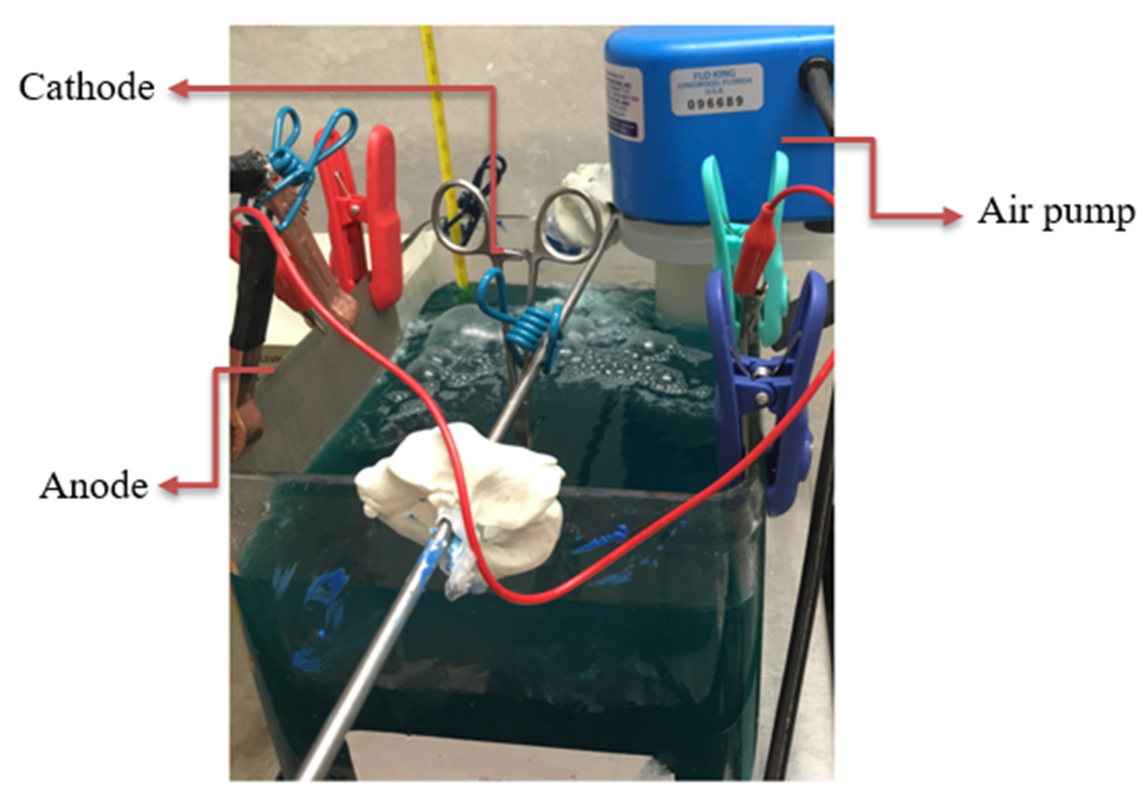
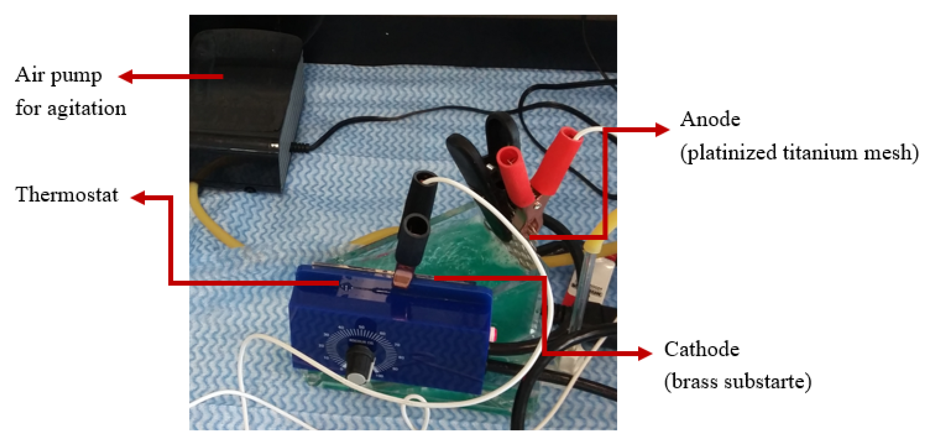
2.2. Electrodeposition Setup

The electrodeposition bath setup (Figure 2) was composed of an electrodeposition tank containing electrolyte, a pump (Flo King Filter System Inc., Longwood, FL, USA) to provide electrolyte agitation, two stainless steel anodes, brass substrate as cathode, and a reversed pulse plating power supply (Model pe8005, Plating Electronic GmbH, Plating Electronic GmbH, Sexau, Berlin, Germany).
Figure 3 displays the Hull cell setup (Figure 3) equipped with heater, thermostat, and air pump. Hull cell was used to perform the initial electrodeposition tests and to optimize the conditions of the electrodeposition. A platinized titanium mesh was used as anode and brass substrate was used as cathode.

2.3. Characterization of Deposits

Surface morphology and elemental composition of the deposits were characterized by using scanning electron microscopy and energy dispersive spectroscopy (SEM–EDS, Joel 7600 TFE, JEOL Ltd., Akishima, Tokyo, Japan) with an acceleration voltage of 20 kV. The observations of surfaces were performed without any specific sample preparation. Grain size analysis were also performed using X–ray diffraction (XRD, Bruker D8 Advance, Bruker AXS, Madison, WI, USA) with Cu–Kα radiation (λ = 0.154 nm) and transmission electron microscopy (TEM, Jeol JEM–2100F, JEOL Ltd, Akishima, Tokyo, Japan) at 200 kV, respectively. The samples were thinned to the thickness of ~100 nm using a Gallium Focused Ion Beam (Ga–FIB, Hitachi FB–2000A, Hitachi High-Tech Kyushu Corporation, Tegama, Omuta-shi, Fukuoka, Japan) at 30 kV.
Various electrochemical corrosion tests including potentiodynamic polarization (PP) and cyclic potentiodynamic polarization (CPP) tests were performed to evaluate the corrosion performance of the deposits. The potentiostat was operated by a PC equipped with corrosion software (CorrWare) enabling the test parameters to be set and the experiments to be conducted. Potentiodynamic polarization (PP) measurements were performed in the potential range of −0.6 to 1.0 V vs. Ecorr at room temperature and scan rate of 5 mV·s−1. Similarly, cyclic potentiodynamic polarization (CPP) scans were performed in the potential range of −0.6 to 1.0 V in forward direction and from 1.0 to −1.0 V in reversed direction at room temperature and 5 mV·s−1 scan rate. For all the PP and CPP experiments, graphite rod was employed as reference electrode and silver/silver sulfate was used as reference electrode. The coated specimens were sealed with an insulating adhesive tape and 1 cm2 of the surface was exposed to artificial sea water. The composition of the artificial sea water is displayed in Table 2.
Wear tests were performed using a custom-built pin-on-disk wear testing machine under dry air conditions and room temperature. The pin specimens were spherical with a diameter of 1.6 mm and were made of steel (AISI). ASTM G99–05 (2010) was used as a standard to conduct the tests. The applied load was 1 N for all the experiments and the sliding speed and the number of revolutions were 100 mm·s−1 and 3500, respectively. The friction experiments were continuously recorded and repeated three times with regard to the sliding distance. Profilometer (Bruker Dektak XT, Bruker Corporation, Billerica, MA, USA) was used to measure the volume of the worn tracks.

3. Results and Discussion

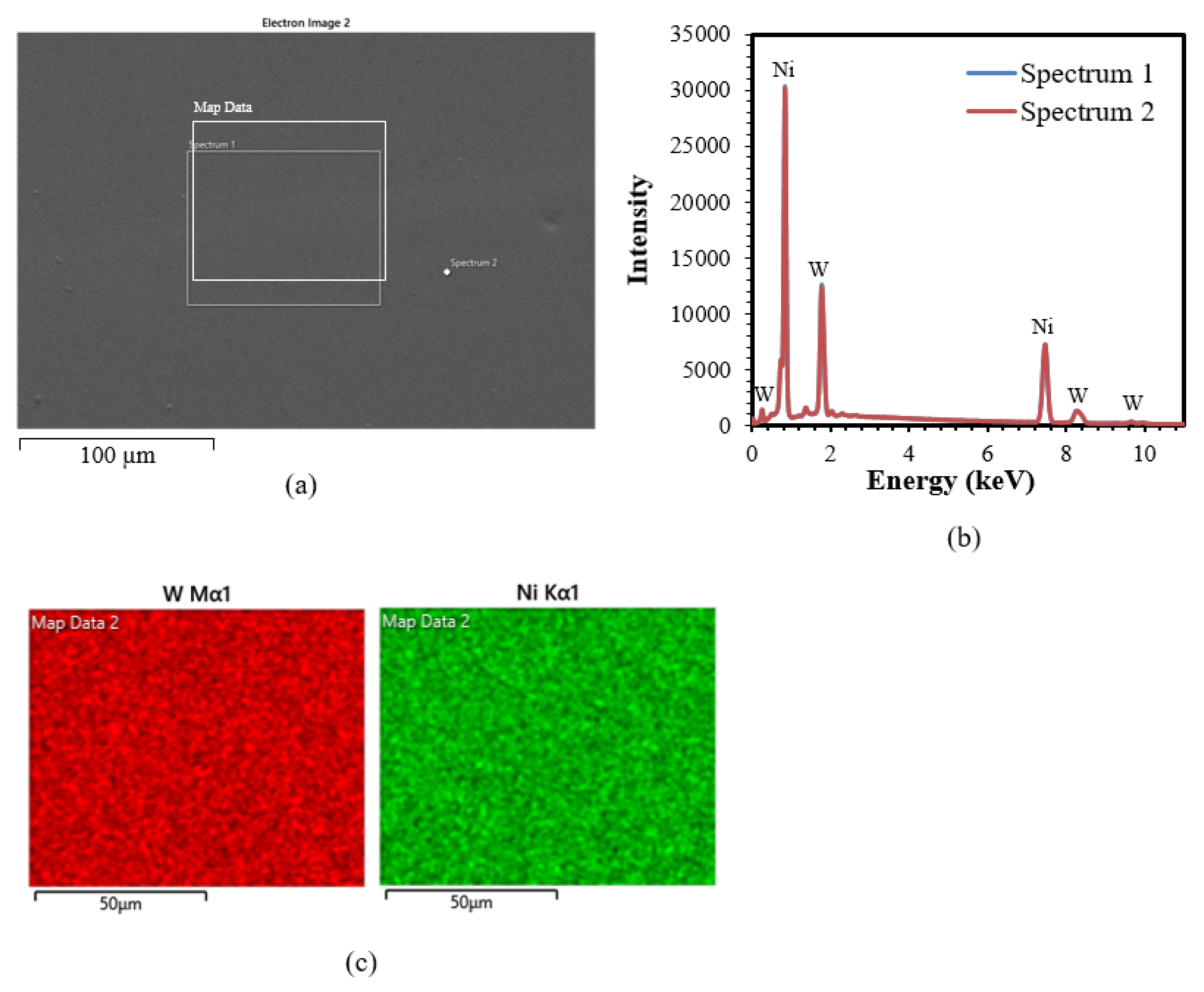
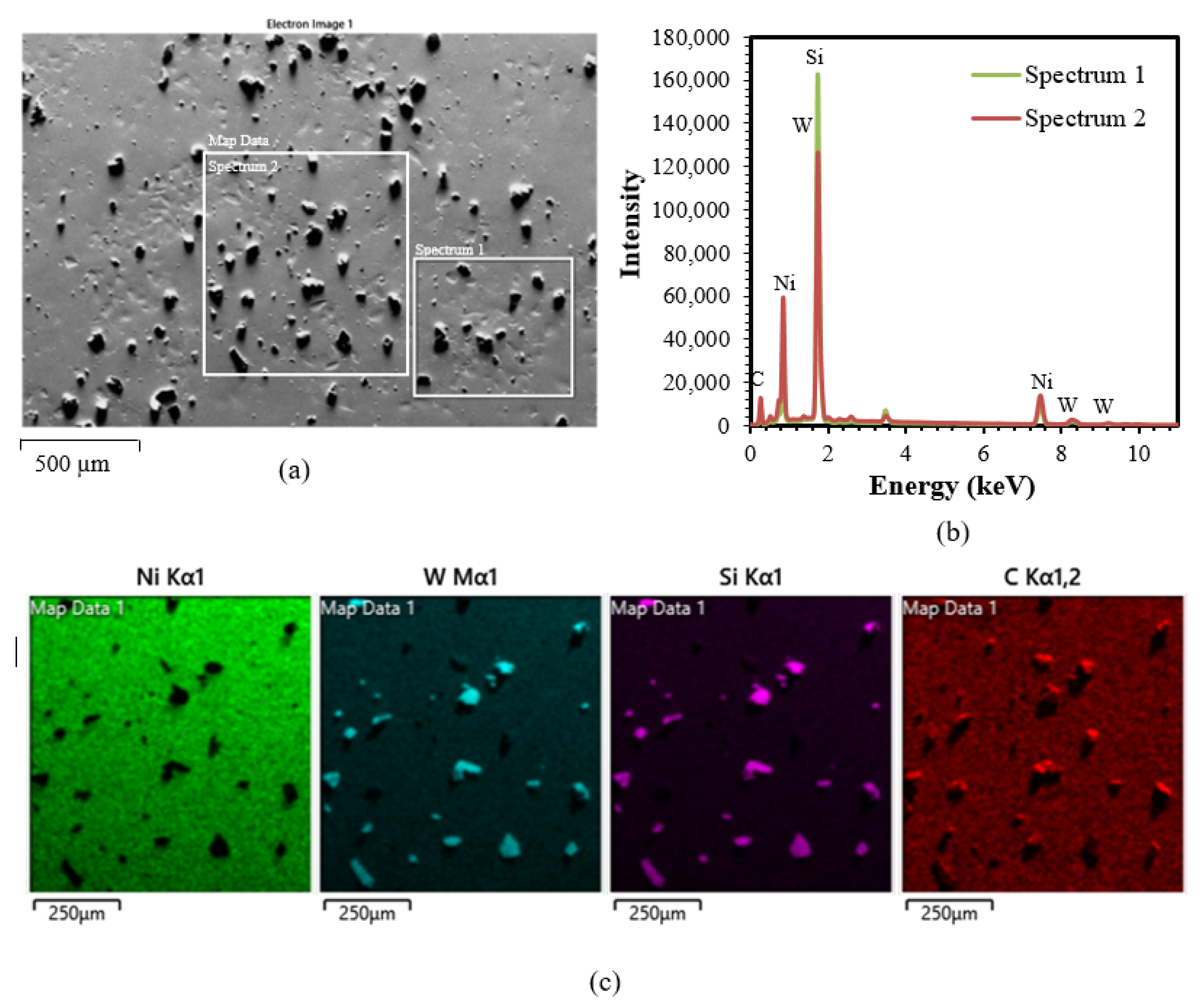
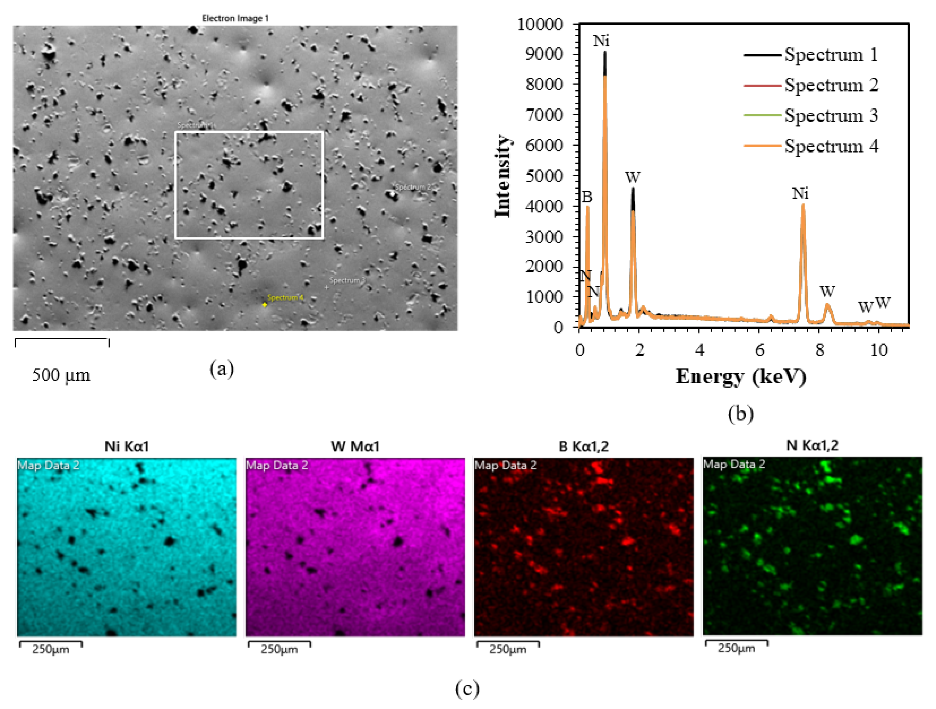
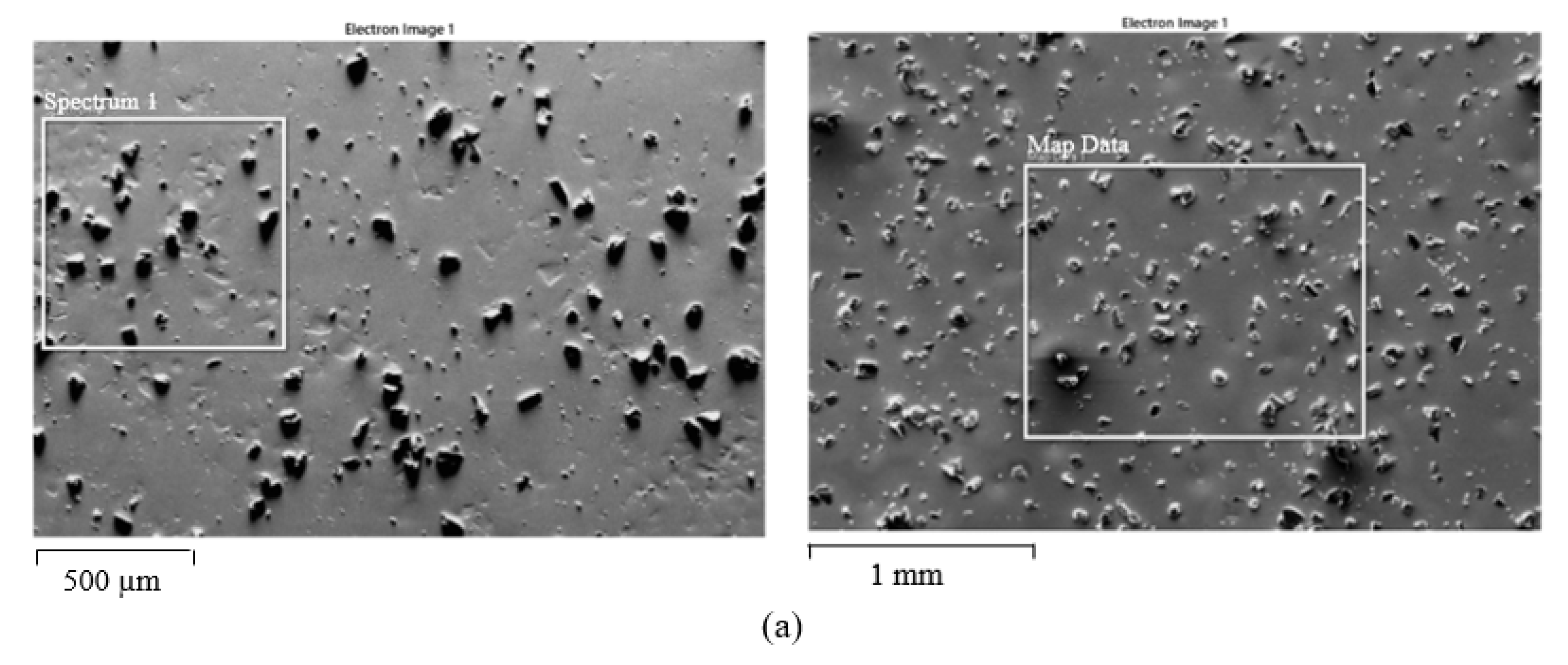
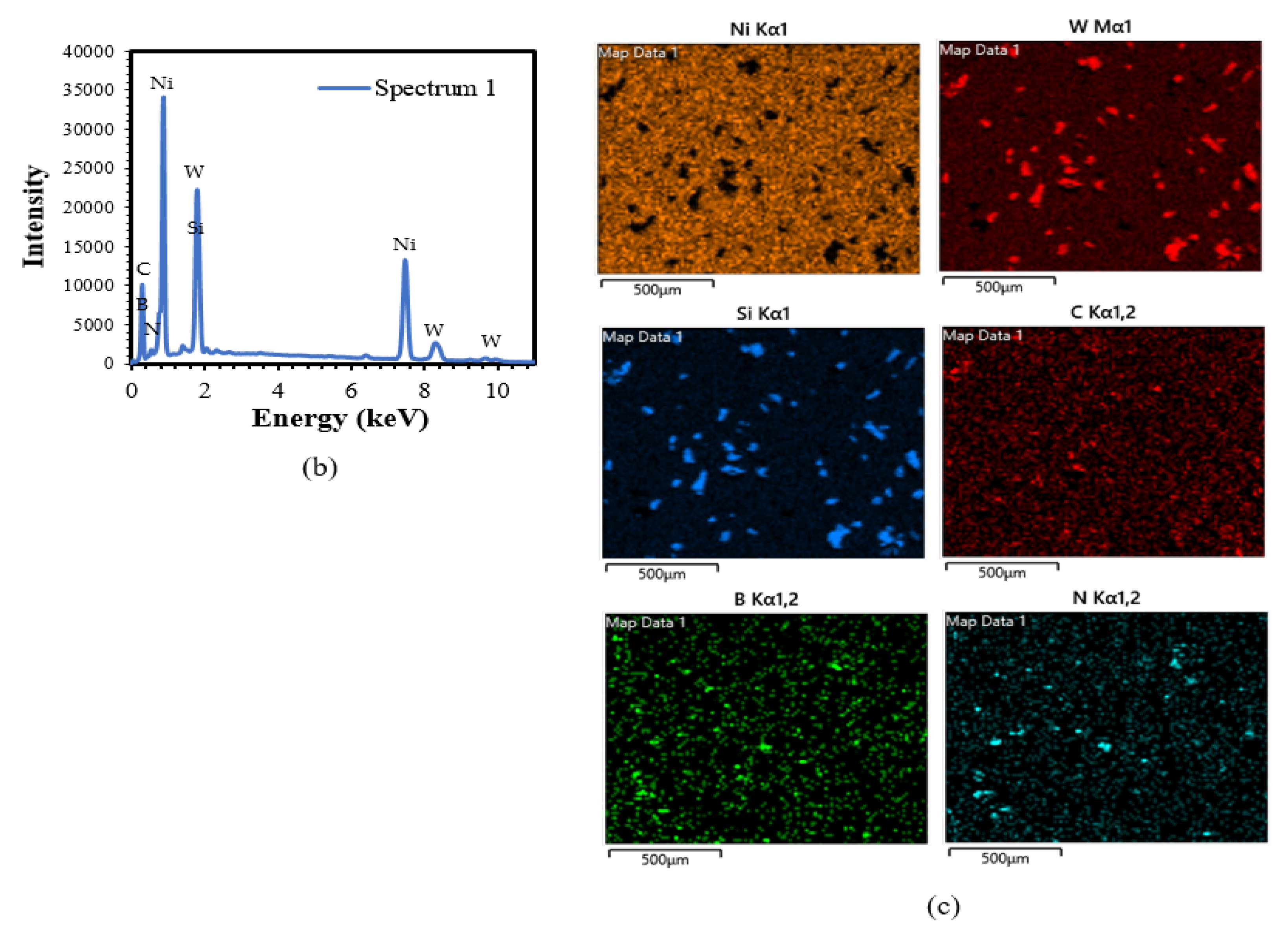
3.1. SEM/EDS Analysis

The SEM images were taken from the surface of NiW electrodeposited on brass substrate (Figure 4a). The micrograph shows that the coating surface is smooth and free of any cracks or defects. This can have a great influence on the durability and on the performance of the coating in terms of corrosion since such surface can greatly prevent the penetration of corrosive agents from reaching the substrate. EDS spectra and X-ray mapping (Figure 4b,c) were also taken from different locations of the DC-deposited NiW. Accordingly, Ni (~65.9 wt%) and W (~34.1 wt%) were the main elements of the coatings (Figure 4b) and were distributed uniformly across the coating surface (Figure 4c). The homogeneous microstructure and elemental distributions can remarkably improve the corrosion and wear performance of the coating.
SEM micrographs (Figure 5a) were taken from the surfaces of the DC-deposited NiW–SiC to examine any possible defects at the surface of coatings. No defect or delamination was observed on the surface of the coatings and SiC particles with average size of 60 µm were uniformly distributed across the surface. Furthermore, EDS spectra and X-ray mapping (Figure 5b,c) taken from various locations on the surface suggest that the elemental composition of the coatings Ni (~45.6 wt%), W (~20.7 wt%), Si (~32.5 wt%), and C (~1.2 wt%) were uniformly distributed throughout the surface. Surface roughness of the coatings can have a remarkable influence on the longevity and performance of the coating in terms of contact stress, friction, and wear. Higher surface roughness may result in a lower contact area and lower adhesion between contact surfaces, minimizing the friction and adhesive wear [30,31].
SEM micrograph (Figure 6a) was taken from the surfaces of the DC-deposited NiW–hBN. No crack or delamination was observed on the surface of the coating and hBN particles with average size of 44 µm were uniformly distributed across the surface. Furthermore, EDS spectra and X-ray mapping (Figure 6b,c) taken from various locations on the surface suggest that the elemental composition of the coatings Ni (~66.2 wt%), W (~24.2 wt%), B (~8.5 wt%), and N (~1.1 wt%) were homogeneously distributed throughout the surface.
SEM micrograph, EDS spectra, and X-ray mapping (Figure 7) were taken from the surfaces of the electrodeposited NiW–SiC–hBN. The coating surface was crack-free without any delamination and coating elements were homogeneously distributed across the surface. As well, EDS spectra and X-ray mapping results suggest that the elemental composition of the coatings Ni (~69.6 wt%), W (~9.3 wt%), Si (~8.6 wt%), C (~5.1 wt%), B (~5.8 wt%), and N (~1.1 wt%) were homogeneously distributed throughout the surface.

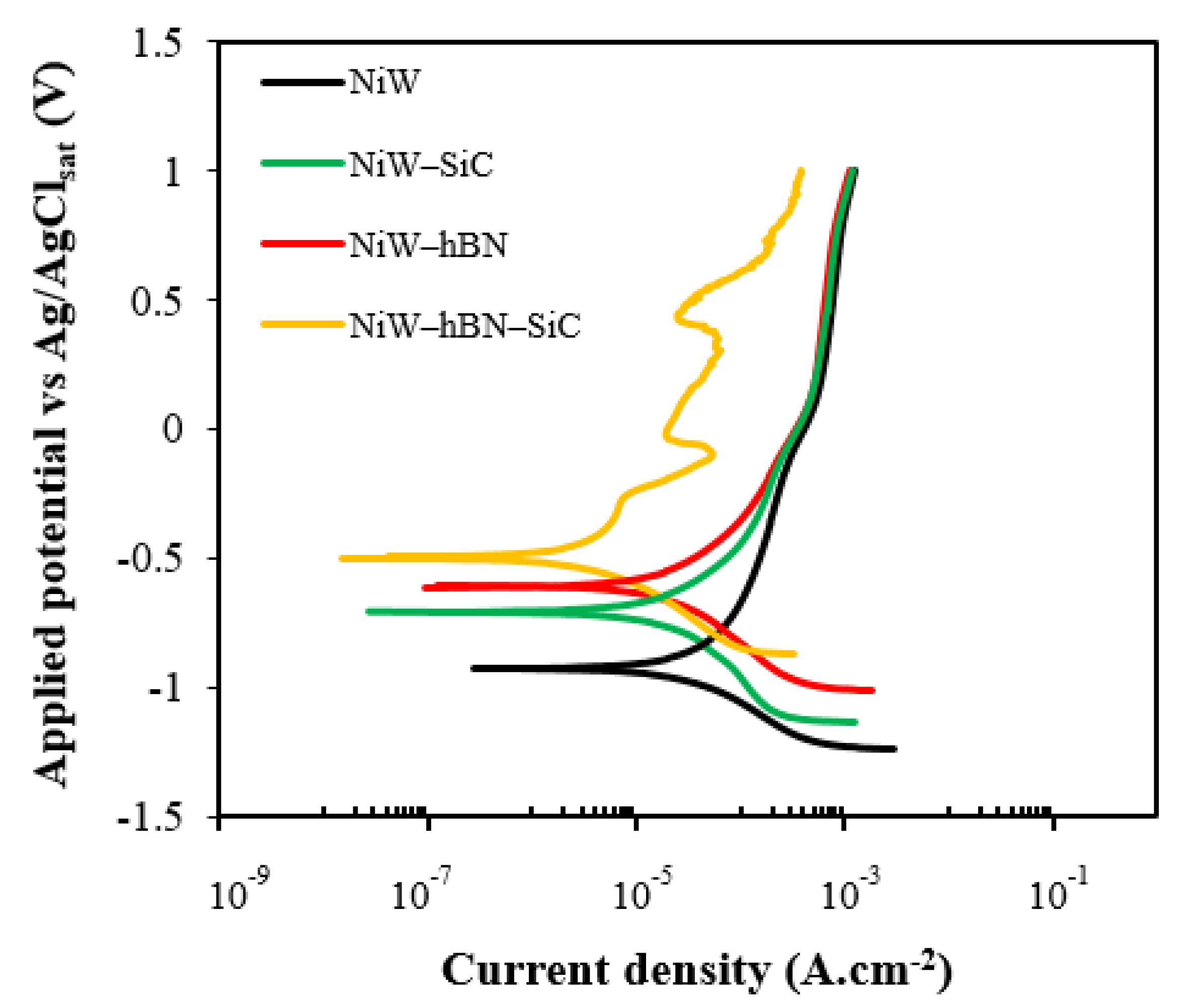
3.2. Potentiodynamic Polarization of DC Electrodeposited of NiW, NiW–hBN, and NiW–hBN–SiC

Potentiodynamic polarization (PP) tests (Figure 8) were performed on the surface of various DC-deposited NiW, NiW–hBN, and NiW–hBN–SiC composites. The intersecting point of the anodic and cathodic polarization curves (Ecorr) showed a significant shift toward the nobler values from −0.92 VAg/AgCl to −0.49 VAg/AgCl and lower current density values were obtained with the addition of SiC, hBN, and mixture of SiC and hBN, respectively (Table 3).
The increase in corrosion potential of NiW toward positive values with the addition of SiC could be attributed to a uniform distribution of SiC particles within the NiW, surface oxidation of SiC particles or presence of SiO2 in the interplanar layers of individual SiC [32,33]. As well, formation of double layer of NiWO4 due to the oxidation of the NiW when exposed to corrosive media. These protective layers will act as physical barriers to initiation and propagation of cracks or defect corrosion and thus hinder the matrix dissolution. Similar observations were reported by Yao and et al., Jin and et al., Li and et al. [22,23,24]. The formation of NiWO4 and SiO2 barrier layers might be attributed to the following reactions [34,35,36]:
Ni2++WO42− → NiWO4
SiC + 4H2O → SiO2 + 8H+ + CO2 + 8e
The formations of NiWO4, SiO2 and CO2 are supported by the zone of stabilities of m potential vs pH diagrams of Ni–H2O, W–H2O, Si–H2O and C–H2O at 25 °C. [37]
Moreover, the corrosion resistance enhancement in NiW with the addition of hBN could be explained by its chemical inertness due to its wide band gap (Eg~5.15 eV) [38] and strong in-plane covalent bond, preventing corrosive ion diffusion to the surface of the electrode.
The results are in agreement with those reported by Sangeetha and et al. [26]. They found that the inclusion of hBN nanoparticles within in the NiW matrix could decrease the cracking, porosity, and pinholes of the coating, improving the shielding effect.
Further improvement of corrosion performance in NiW by incorporating a mixture of SiC and hBN could be related to taking advantage of the properties of both ceramic particles for example combination of chemical inertness of hBN together with the formation of protective layers of NiWO4 and SiO2. Similar to hBN, SiC is also a wide band gap semiconductor (Eg~3.26 eV). [39]
According to potentiodynamic polarization (PP) graphs, NiW–SiC–hBN coatings displayed active–passive transitions, and relatively small passive regions were observed that could be attributed to slightly defective passive films. Presence of active–passive transitions in the anodic curve indicates that the time used to scan the potential range where passivation is expected to occur is much longer than the natural timescale required to obtain the passive film. If the material does not go under active–passive transition, it would corrode at much higher rate in the corrosive environment. Formation of a passive layer offers a great protection against the ionic and electronic diffusions and lowers the corrosion rate of the metal. It also has self-repairing ability after the rupture. The performance of passive layer in corrosive media is affected by many factors, such as pH, temperature, and dissolved oxygen content [40,41,42,43].

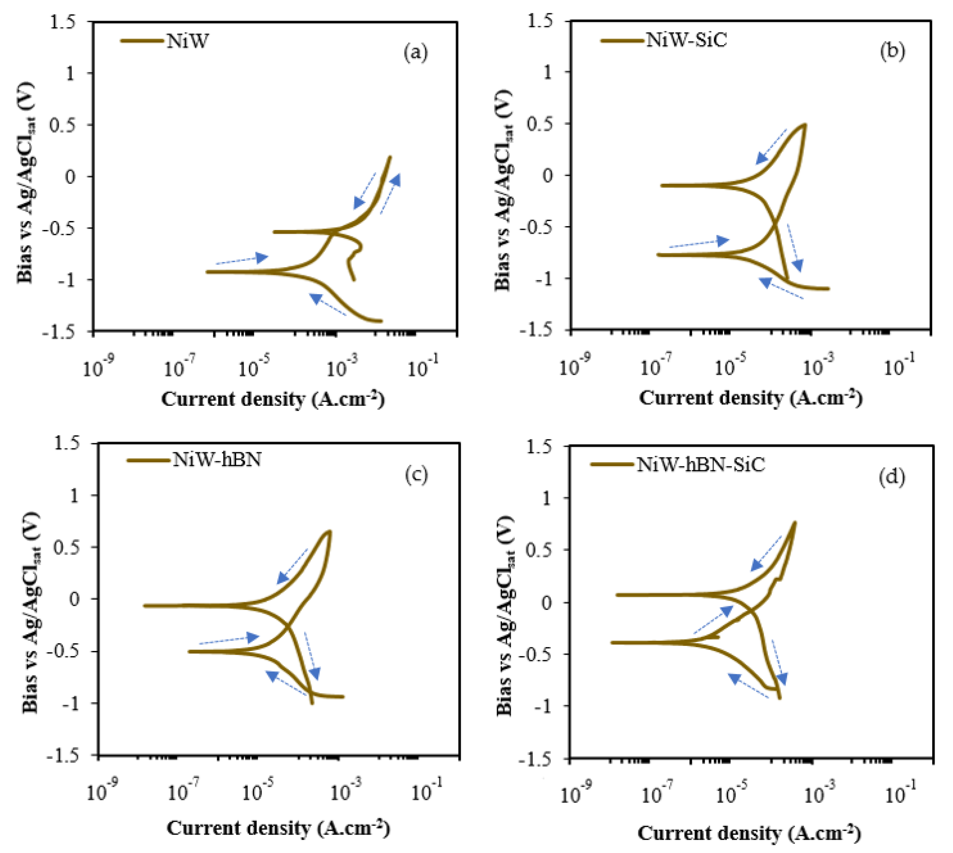
3.3. Cyclic Polarization of DC Electrodeposited NiW, NiW–hBN, and NiW–hBN–SiC

Figure 9 displays the CPP graphs for DC electrodeposited NiW, NiW–SiC, NiW–hBN, and NiW–hBN–SiC coatings. In the anodic polarization scan, the potential scanning begins from the corrosion potential (Ecorr). A rapid rise in anodic current density at the potential below the potential of oxygen evolution can be due to: (1) Local dissolution of passive films and formation of metastable pits in the presence of aggressive Cl ions; (2) presence and propagation of active defects on the surface of passive layer. The potential at which current density increases sharply is called critical pitting potential, pitting potential, rupture potential, or breakdown potential [44,45,46]. In order to investigate the materials’ response to the pitting corrosion, the scanning direction of the potential was changed at the pitting potential from positive values toward the negative values. It can be observed that DC-deposited NiW exhibits a zero hysteresis loop, while NiW–hBN, NiW–SiC, and NiW–hBN–SiC indicate negative hysteresis loop, depicting repassivation of pits. In fact, reverse anodic curve is shifted to lower current densities in contrast to the forward anodic scan. This indicates the uniform corrosion and reconstruction of the damaged passive layer at higher potentials. As well, the corrosion potential for the electrodeposited NiW–hBN and NiW–hBN–SiC appeared to be similar and nobler compared to NiW and NiW–SiC coatings due to hBN’s chemical inertness. As it is seen in Figure 9, all deposits displayed anodic to cathodic transition potential. During the reversal scan, the rapid decrease in corrosion current density at anodic nose or active–passive transition potential was observed at more positive potentials compared to Ecorr. Therefore, the potential of the corroded region is nobler than the un-corroded area. This behavior is usually characteristics of materials that are susceptible to passivation or the materials that are not susceptible to pitting corrosion [40,41,42,43].

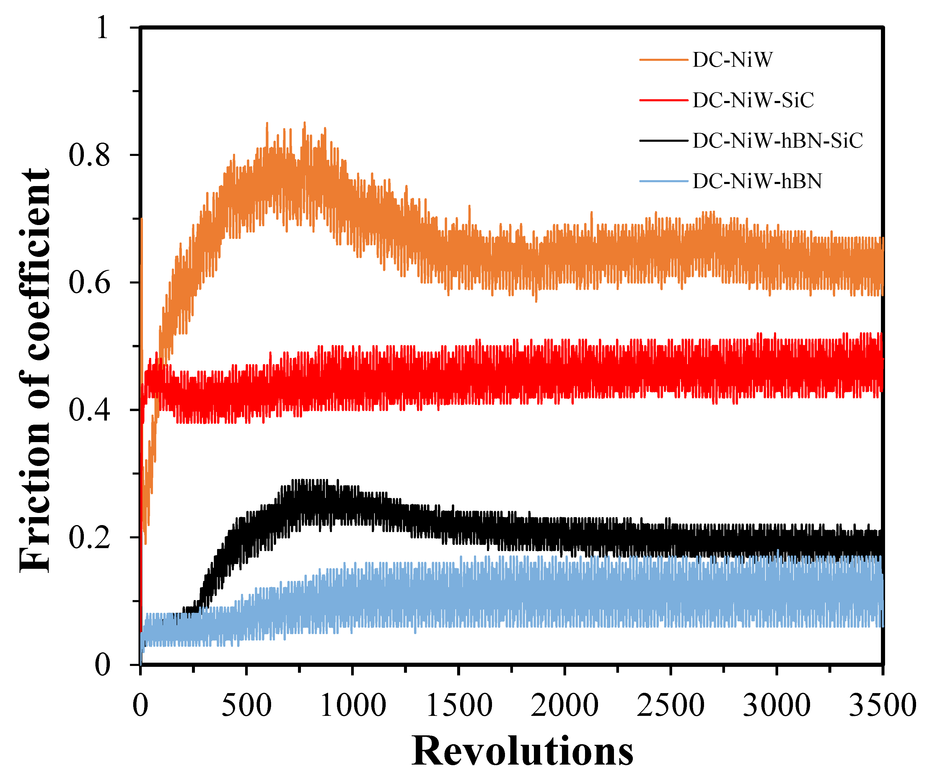
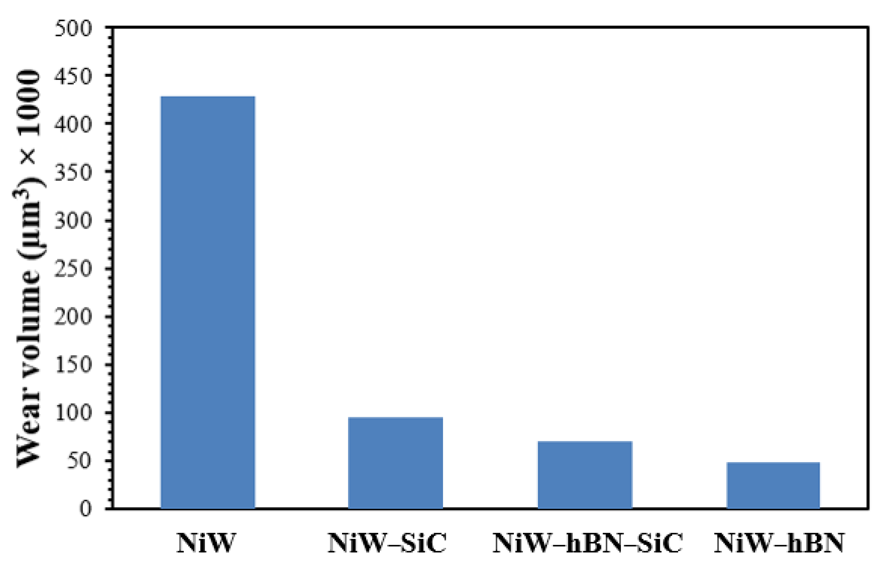
3.4. Tribological Analysis (Coefficient of Friction and Wear Rate)

Figure 10 displays the variation in the average coefficient of friction of NiW, NiW–hBN, and NiW–hBN–SiC materials, respectively, DC-electrodeposited on brass substrate using pin-on-disc wear testing equipment. As it can be seen, the DC electrodeposit of NiW–hBN demonstrated a lower coefficient of friction (0.1) compared to those of the DC electrodeposits of NiW–hBN–SiC (0.2), NiW–SiC (0.4), and NiW (0.6), respectively. This is attributed to the ultra-low coefficient and anisotropic structure of hBN consisting of covalently bonded boron and nitrogen intra-layers stacked together by weak interlayer van der Waals forces providing efficient inter-layer sliding effect. As well, presence of SiC particles in the NiW matrix will effectively reduce the contact between the sliding surfaces due to the formation of stable SiO2. Figure 11 displays the wear volume rate of each coating after the friction test.

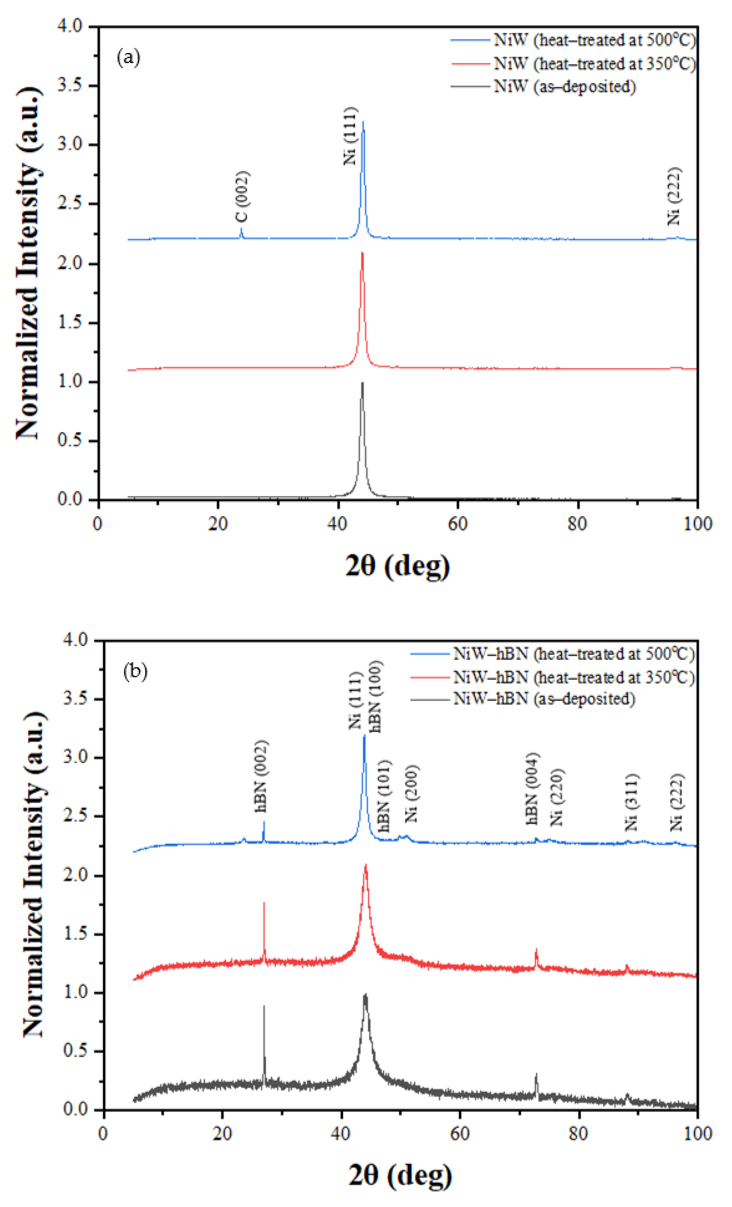
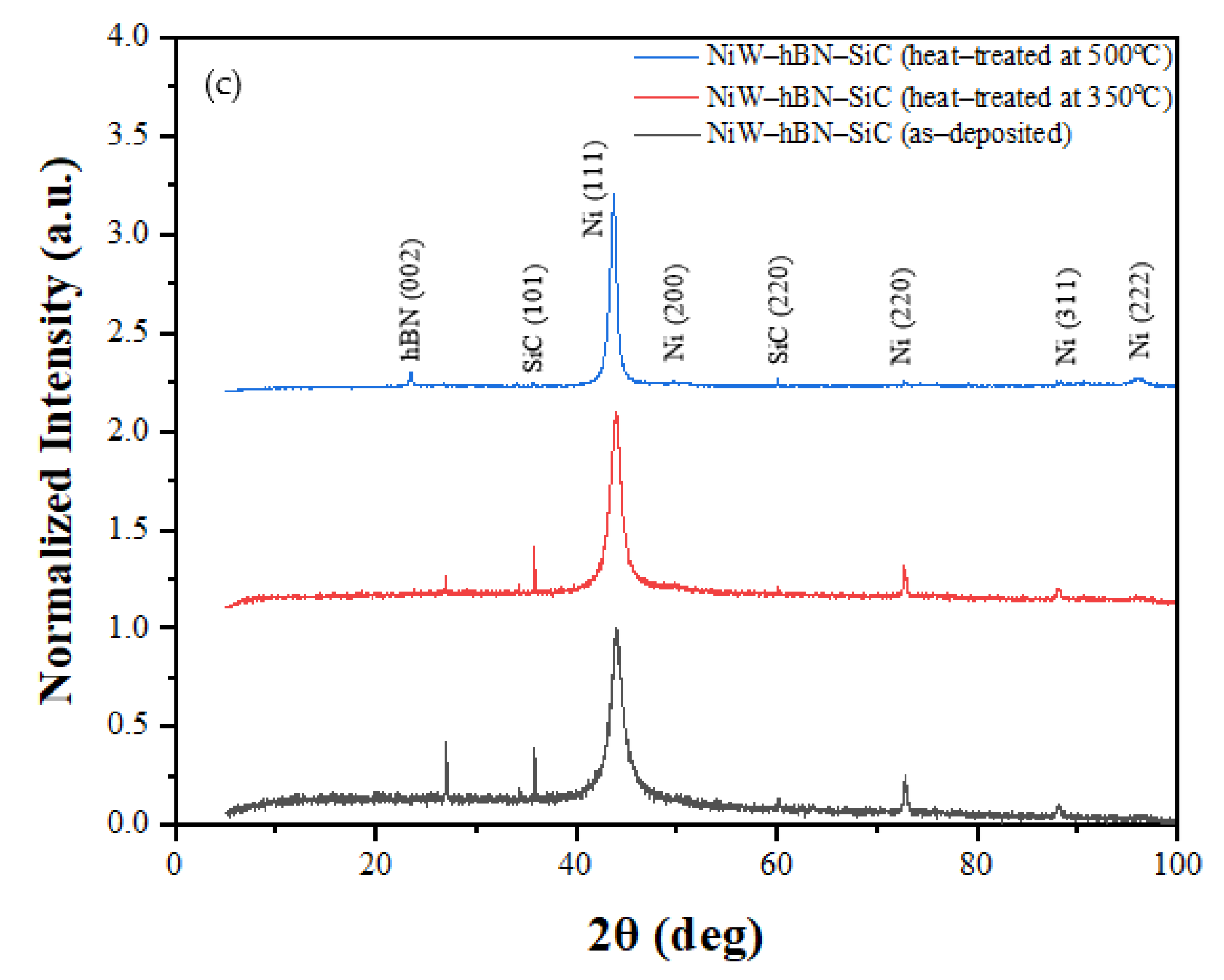
3.5. XRD Analysis (Influence of Annealing on Crystallite Sizes of DC Electrodeposited NiW, NiW–hBN, and NiW–hBN–SiC)
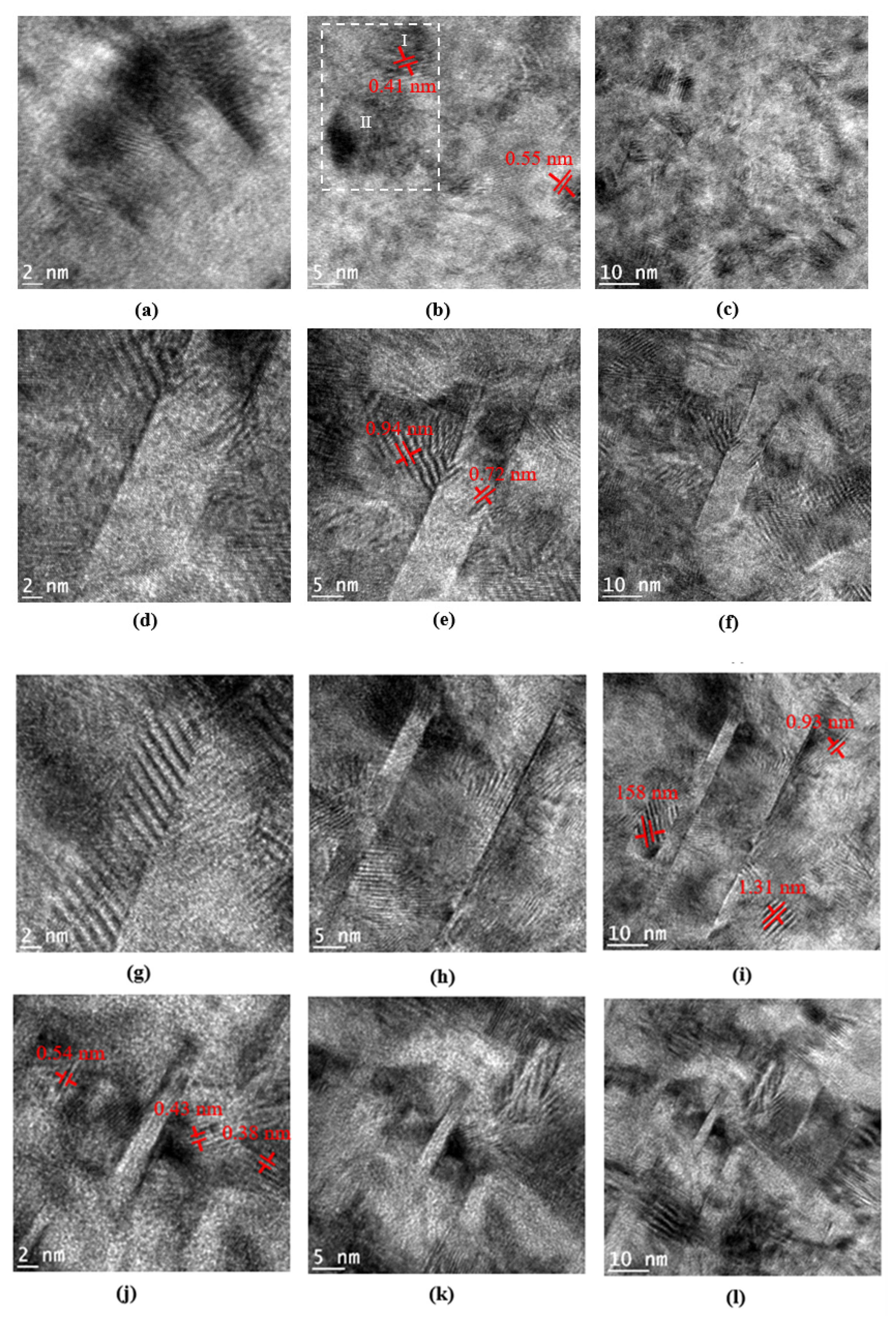
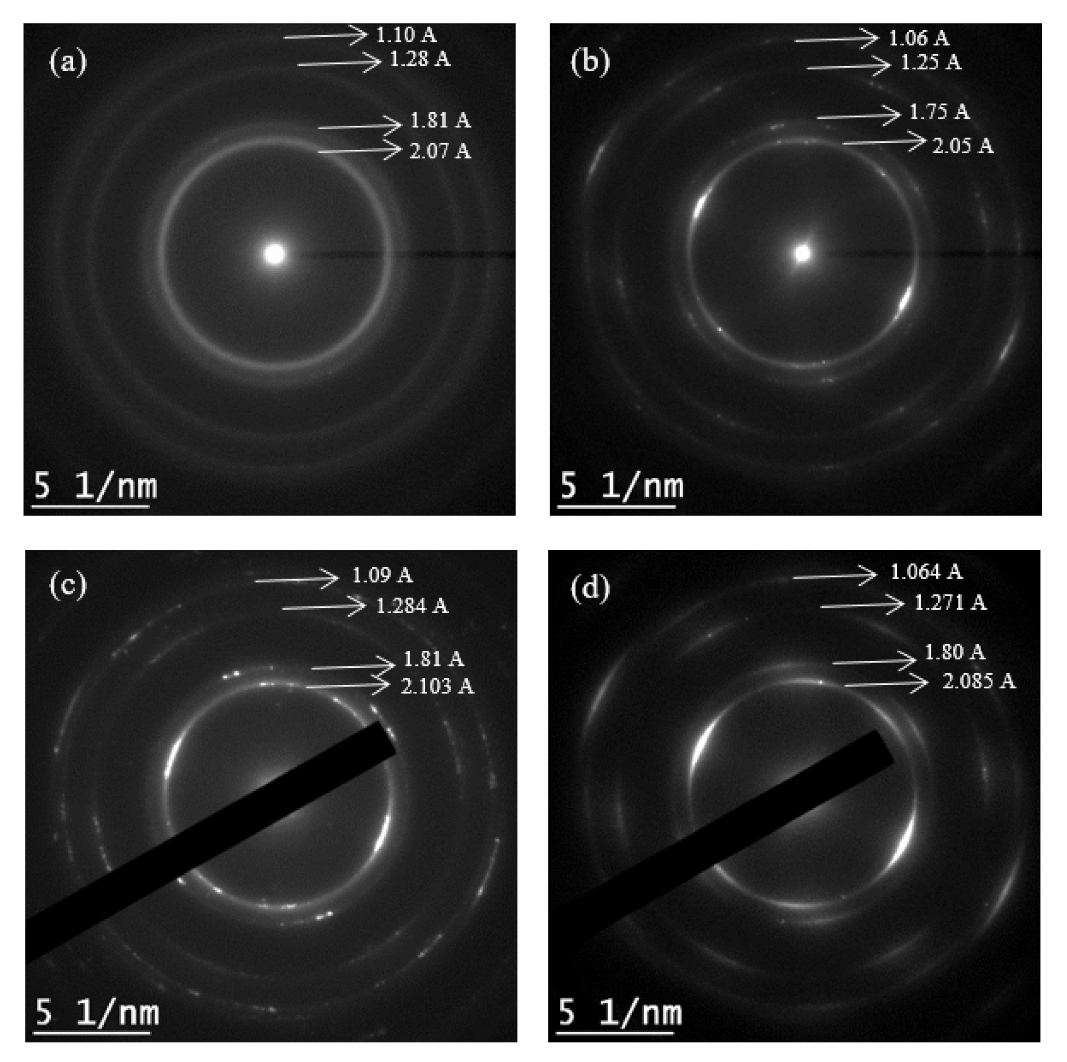
Curves (a), (b) and (c) of Figure 12 display, respectively, the XRD patterns obtained from the surfaces of as-deposited and heat-treated NiW, NiW–hBN, and NiW–SiC–hBN at 350 and 500 °C on brass substrates. No significant differences were found between the XRD patterns of heat-treated and as-deposited coatings. However, crystallite size and peak intensity of the as-deposited coatings were lower than those of the annealed coatings. The increase in peak intensity and crystallite size as a function of annealing temperature can be attributed to FCC crystal grain growth, phase transformation from amorphous type to crystalline structure, and reduction in internal micro-strains.
The crystallites size (D) of the coatings were calculated (Table 4) from the broadening of the (111) peaks using Scherrer equation [47].
D = Kλ/βcosθ
where D is the crystallite size (nm), K is the Scherrer constant (0.9), λ is the wavelength of the X-ray source (Cu–Kα, 0.15406 nm), β is the FWHM (radians), and θ is the peak position (radians).
As we can see in Figure 12b, the diffraction peaks of DC-deposited NiW–hBN were assigned to the Ni (111), Ni (200), Ni (220), Ni (311), Ni (222), hBN (002), hBN (100), hBN (101), and hBN (004) planes, respectively. The intensity of the peaks and average crystallite size as displayed in Table 4 increases from 68 Å up to 261 Å with rising the annealing temperature. This was attributed to an increase in crystallinity of the coating and hence increase in number of the crystallites with the increase of the temperature.
It was noticed that the intensity of the Ni (111) was increased and additional peaks of hBN (101) and Ni (200) were formed after heat treatment at 500 °C. Furthermore, the average crystallite size increased with the increase of the temperature. The results of the average grain size before and after annealing at 350 and 500 °C are presented in Table 4.
Similar results are obtained from Figure 12c which shows the XRD spectra from the surface of as-deposited and annealed electrodeposited NiW–hBN–SiC at 350 and 500 °C.
As presented in Table 4, incorporation of SiC and hBN in the DC electrodeposited NiW matrix resulted in a decrease in the crystallite size compared to DC–NiW due to micro-strain, lattice distortion of the Ni (W) matrix and grain refinement effect of SiC and hBN particles. The smaller grain size promotes the formation of highly dense and stable passive films with a lower defect density due to a higher amount of active surface atoms. This can repel the adsorption of chloride ions on the surface of the coating and remarkably improves the pitting corrosion and wear performance of the coatings [48,49,50,51].
It was also observed that intensity of Ni (111), Ni (200) were higher with the increase of the annealing temperature. However, some peaks of SiC (101) disappeared after annealing at 500 °C which could be attributed to the decomposition of SiC at high temperatures. Furthermore, the influence of annealing temperature on average crystallite size was investigated. It was found that the average grain size increased from 90 to 165 Å by increase of the annealing temperature from 350 °C up to 500 °C.

3.6. TEM Analysis

Crystal structure of the DC-electrodeposited NiW, NiW–SiC, NiW–hBN, and NiW–hBN–SiC samples was investigated by TEM at 200 kV in bright-field (BF) imaging mode (Figure 13). TEM samples were cut at the thickness of ~100 nm by focused ion beam (FIB) at normal operating parameters to allow the electron beam to transmit through the ultra-thin samples to form an image. The DC–NiW sample presented mainly a dominant amorphous phase structure, while the DC-deposited NiW–SiC, NiW–hBN, and NiW–hBN–SiC samples exhibited mostly crystalline structure with high crystallographic texture. Figure 13d–l revealed plenty of nanotwin bundles for DC electrodeposited NiW–SiC, NiW–hBN, and NiW–hBN-SiC with an average inter-plane distances of 0.63, 0.53, and 0.43 nm formed throughout the surface of the samples. However, DC–NiW coating (Figure 13a–c) displayed only few nano-scale twin bundles with average inter-plane distance of 0.47 nm. Nanograins and nanotwins in the coatings can remarkably improve the mechanical, tribological, as well as corrosion properties of coatings by serving as strong dislocation barriers, altering the microstructure, and semiconducting response of the passive film [52,53]. Figure 13b is the high resolution TEM (HRTEM) image revealing the presence of two nanograins with different orientations (marked in dotted box). In between two nanograins, there is a presence of amorphous structure.
Figure 14 shows the selected area of the electron diffraction (SAED) pattern of DC-electrodeposited NiW, NiW–SiC, NiW–hBN, and NiW–hBN–SiC coatings, respectively. DC–NiW reveals diffused ring patterns suggesting the existence of dominant amorphous phase, while the DC electrodeposited NiW–hBN and NiW–hBN–SiC exhibit the non-continuous rings, which is indicative of a crystalline structure with preferred orientation in the microstructure. The interplanar spacings between the atoms can be calculated by measuring the radius of these circular rings. The value of miller indices (hkl) or the phase structure of the materials can be obtained by comparing the estimated values of interplanar spacings derived from SAED rings with the standard values available from JCPDS data cards. According to these values, the primary constituent phase is FCC Ni with random grain orientation. Therefore, the diffraction pattern analysis from Tem confirms the XRD results.

4. Conclusions

In this research work, NiW filled with hBN and SiC nanocomposite coatings were successfully fabricated via DC electrodeposition and their morphological features, grain structure, electrochemical and wear properties of the coatings were investigated, and the following results were obtained:
  • Inclusion of wide band gap semiconductors particles such as hBN and SiC within NiW is shown to enhance the corrosion and wear performance of electrodeposited NiW coatings by altering the morphological features, composition, grain structure, and surface properties of the coatings.
  • The coatings were uniform, compact without defects or any cracks. Elemental distribution map also confirmed that the SiC and hBN particles were homogeneously distributed within the NiW matrix.
  • Incorporation of hBN and SiC ceramic particles within the NiW matrix enhanced the corrosion performance of the NiW coating. Several sets of experiments were performed to investigate the corrosion performance of the NiW coatings reinforced with hBN and SiC ceramic particles. It was observed that that reinforcement of hBN within NiW and NiW–SiC significantly improved the corrosion performance of the coating and NiW–SiC–hBN exhibited the highest corrosion performance compared to DC-deposited NiW, NiW–SiC, and NiW–hBN. According to potentiodynamic polarization test results, the corrosion resistance improves in the following order for deposits:
NiW < NiW–SiC < NiW–hBN < NiW–SiC–hBN
  • According to wear performance results, NiW–hBN demonstrated the lowest wear rate and coefficient of friction (0.04) compared to NiW–SiC–hBN (0.15), DC–NiW–SiC (0.4), and DC–NiW deposits (0.6).
  • The XRD results obtained from the surfaces of the as-deposited and annealed DC-deposited NiW, NiW–hBN, and NiW–SiC–hBN at 350 and 500 °C also revealed that the intensity of the peaks and the average crystallite size increased with the annealing temperature up to 500 °C. Inclusion of hBN and SiC within NiW also reduced the grain size due to micro-strain and lattice distortion of the Ni (W) matrix.
  • According to BF-TEM results, plenty of nanotwin bundles were formed across the surface of DC-deposited NiW–hBN and NiW–hBN–SiC coatings. However few nano-twin bundles were observed on the surface of DC-NiW coating. Nanotwins can effectively hinder the dislocation motion, and therefore enhance the tribological performance of the coatings.

Author Contributions

Conceptualization, M.D. and O.S.; methodology, M.D.; software, M.D.; validation, M.D. and O.S.; formal analysis, M.D.; investigation, M.D.; resources, O.S.; data curation, M.D.; writing—original draft preparation, M.D.; writing—review and editing, M.D. and O.S.; visualization, M.D.; supervision, O.S.; project administration, O.S.; funding acquisition, O.S. All authors have read and agreed to the published version of the manuscript.

Funding

Laboratory of New Materials for Electrochemistry and Energy (LANOMAT), Montreal.

Institutional Review Board Statement

Not applicable.

Informed Consent Statement

Not applicable.

Data Availability Statement

Not applicable.

Conflicts of Interest

The authors declare that they have no known competing financial interests or personal relationships that could have appeared to influence the work reported in this paper.

References

  1. Feyzullahoğlu, E.; Zeren, A.; Zeren, M. Tribological behaviour of tin-based materials and brass in oil lubricated conditions. Mater. Des. 2008, 29, 714–720. [Google Scholar] [CrossRef]
  2. Liu, C.; Huang, X.; Xu, R.; Mai, Y.; Zhang, L.; Jie, X. Microstructure and Properties of Nanocrystalline Ni-Mo Coatings Prepared by Ultrasound-Assisted Pulse Electrodeposition. J. Mater. Eng. Perform. 2021, 30, 2514–2525. [Google Scholar] [CrossRef]
  3. Dinaharan, I.; Karpagarajan, S.; Palanivel, R.; Raja Selvam, D.J. Microstructure and sliding wear behavior of fly ash reinforced dual phase brass surface composites synthesized through friction stir processing. Mater. Chem. Phys. 2021, 263, 124430. [Google Scholar] [CrossRef]
  4. Wang, X.; Chou, C.C.; Lee, W.J.; Wu, R.; Chang, H.Y.; Ding, Y. Preparation and investigation of diamond-incorporated copper coatings on a brass substrate by composite electrodeposition. Surf. Coat. Technol. 2020, 386, 125508. [Google Scholar] [CrossRef]
  5. Reeves, J.C.; Menezes, P.L.; Lovell, M.R.; Jen, T.C. Tribology of Solid Lubricants; Springer: New York, NY, USA, 2013; pp. 447–494. [Google Scholar]
  6. Joseph, A.; Gautham, V.; Akshay, K.; Sajith, V. 2D MoS2-hBN hybrid coatings for enhanced corrosion resistance of solid lubricant coatings. Surf. Coat. Technol. 2022, 443, 128612. [Google Scholar] [CrossRef]
  7. Zhao, B.; Ding, W.; Jiang, G.; Li, X.; Xu, J. Investigation on microstructure characteristics and tribological properties of self-lubricating metallic composites based on hexagonal boron nitride and molybdenum disulphide. J. Tribol. 2021, 143, 021902. [Google Scholar] [CrossRef]
  8. Kumar, A.; Malik, G.; Chandra, R.; Mulik, R. Bluish emission of economical phosphor h–BN nanoparticle fabricated via mixing annealing route using non–toxic precursor. J. Solid State Chem. 2020, 288, 121430. [Google Scholar] [CrossRef]
  9. An-Hua, R. Effect of current density on the properties of Ni–CeO2 composite coatings prepared using magnetic field–assisted jet electrodeposition. Int. J. Electrochem. Sci. 2021, 16, 210658. [Google Scholar] [CrossRef]
  10. Guo, S.; Wang, L.; Jin, Y.; Piao, N.; Chen, Z.; Tian, G.; Li, J.; Zhao, C.; He, X. A polymeric composite protective layer for stable Li metal anodes. Nano Converg. 2020, 7, 21. [Google Scholar] [CrossRef]
  11. Cao, J.; Wang, L.; He, X.; Fang, M.; Gao, J.; Li, J.; Deng, L.; Chen, H.; Tian, G.; Wang, J.; et al. In situ prepared nano–crystalline TiO2–poly(methyl methacrylate) hybrid enhanced composite polymer electrolyte for Li–ion batteries. J. Mater. Chem. A 2013, 1, 5955–5961. [Google Scholar] [CrossRef]
  12. Yao, Y.; Dong, H.; Jiao, L.; Yu, N.; He, L. Preparation and Electrocatalytic Property of PbO2–CeO2 Nanocomposite Electrodes by Pulse Reverse Electrodeposition Methods. J. Electrochem. Soc. 2016, 163, D179–D184. [Google Scholar] [CrossRef]
  13. Bao, Y.; Liu, Y.H.; Liu, Q.; Gao, L.L.; Zhang, C.Q. Mechanical states of repaired full–thickness defects of articular cartilage by tissue engineering under compression. Appl. Mech. Mater. 2013, 395, 658–661. [Google Scholar] [CrossRef]
  14. Wang, L.; Xing, S.; Liu, H.; Jiang, C.; Ji, V. Improved wear properties of NiTi nanocomposite coating with tailored spatial microstructures by extra adding CeO2 nanoparticles. Surf. Coat. Technol. 2020, 399, 126119. [Google Scholar] [CrossRef]
  15. Pompei, E.; Magagnin, L.; Lecis, N.; Cavallotti, L.P. Electrodeposition of nickel–BN composite coatings. Electrochim. Acta 2009, 54, 2571–2574. [Google Scholar] [CrossRef]
  16. Shrestha, K.N.; Hamal, B.D.; Saji, T. Composite plating of Ni–P–Al2O3 in two steps and its anti–wear performance. Surf. Coat. Technol. 2004, 183, 247–253. [Google Scholar] [CrossRef]
  17. Pushpavanam, M.; Natarajan, R.S. Nickel–boron nitride electrocomposites. Met. Finish. 1996, 6, 97–99. [Google Scholar] [CrossRef]
  18. Teruyama, S.; Shrestha, N.; Ito, Y.; Iwanaga, M.; Saji, T. Plating of Ni/c–BN composite film in two steps. J. Mater. Sci. 2004, 39, 2941–2943. [Google Scholar] [CrossRef]
  19. Gyawali, G.; Adhikari, R.; Kim, S.H.; Cho, H.B.; Lee, S.W. Effect of h–BN Nanosheets Codeposition on Electrochemical Corrosion Behavior of Electrodeposited Nickel Composite Coatings. ECS Electrochem. Lett. 2012, 2, C7–C10. [Google Scholar] [CrossRef]
  20. Tarkowski, L.; Indyka, P.; Bełtowska-Lehman, E. XRD characterisation of composite Ni–based coatings prepared by electrodeposition. Nucl. Instrum. Methods Phys. Res. Sect. B 2012, 284, 40–43. [Google Scholar] [CrossRef]
  21. Atanassov, N.; Gencheva, K.; Bratoeva, M. Properties of nickel–tungsten alloys electrodeposited from sulfamate electrolyte. Plat. Surf. Finish. 1997, 84, 67–74. [Google Scholar]
  22. Jinlong, L.; Zhuqing, W.; Tongxiang, L.; Suzuki, K.; Hideo, M. Effect of tungsten on microstructures of annealed electrodeposited Ni–W alloy and its corrosion resistance. Surf. Coat. Technol. 2018, 337, 516–524. [Google Scholar]
  23. Younes-Metzler, O.; Gileadi, E. Electroplating of Ni/W Alloys. J. Electrochem. Soc. 2002, 149, C100. [Google Scholar] [CrossRef]
  24. Klimenkov, M.; Haseeb, A.S.M.A.; Bade, K. Structural investigations on nanocrystalline Ni–W alloy films by transmission electron microscopy. Thin Solid Film. 2009, 517, 6593–6598. [Google Scholar] [CrossRef]
  25. Sriraman, R.K.; Sundara, G.S.; Raman, S.; Seshadri, K. Synthesis and evaluation of hardness and sliding wear resistance of electrodeposited nanocrystalline Ni–Fe–W alloys. Mater. Sci. Technol. 2013, 22, 14–20. [Google Scholar] [CrossRef]
  26. Sangeetha, S.; Kalaignan, P.G. Tribological and electrochemical corrosion behavior of Ni–W/BN (hexagonal) nano–composite coatings. Ceram. Int. 2015, 41, 10415–10424. [Google Scholar]
  27. Li, H.; He, Y.; He, T.; Qing, D.; Luo, F.; Fan, Y.; Chen, X. Ni–W/BN(h) electrodeposited nanocomposite coating with functionally graded microstructure. J. Alloys Compd. 2017, 704, 32–43. [Google Scholar] [CrossRef]
  28. Eroglu, D.; West, C.A. Mathematical modeling of Ni/SiC co-deposition in the presence of a cationic dispersant. J. Electrochem. Soc. 2013, 160, D354–D360. [Google Scholar] [CrossRef]
  29. Fransaer, J.; Celis, P.J.; Roos, J. Analysis of the electrolytic codeposition of non–brownian particles with metals. J. Electrochem. Soc. 1992, 139, 413. [Google Scholar] [CrossRef]
  30. Hsia, C.F.; Franklin, S.; Audebert, P.; Brouwer, M.A.; Bonn, D.; Weber, B. Rougher is more slippery: How adhesive friction decreases with increasing surface roughness due to the suppression of capillary adhesion. Phys. Rev. Res. 2021, 3, 043204. [Google Scholar] [CrossRef]
  31. Elleuch, R.; Elleuch, K.; Ben Abdelounis, H. Surface roughness effect on friction behaviour of elastomeric material. Mater. Sci. Eng. A 2007, 465, 8–12. [Google Scholar] [CrossRef]
  32. Brozek, V. Corrosion of Ceramic Silicon Carbide in Hydrofluoric Acid. Ceram.-Silik. 2021, 65, 158–169. [Google Scholar] [CrossRef]
  33. Li, H.; Sun, J. Highly Selective Photocatalytic CO2 Reduction to CH4 by Ball-Milled Cubic Silicon Carbide Nanoparticles under Visible-Light Irradiation. ACS Appl. Mater. Interfaces 2021, 13, 5073–5078. [Google Scholar] [CrossRef] [PubMed]
  34. Farsi, H.; Hosseini, S.A. The electrochemical behaviors of methylene blue on the surface of nanostructured NiWO4 prepared by coprecipitation method. J. Solid State Electrochem. 2013, 17, 2079–2086. [Google Scholar] [CrossRef]
  35. Niu, L.; Li, Z.; Xu, Y.; Sun, J.; Hong, W.; Liu, X.; Wang, J.; Yang, S. Simple synthesis of amorphous NiWO4 nanostructure and its application as a novel cathode material for asymmetric supercapacitors. ACS Appl. Mater. Interfaces 2013, 5, 8044–8052. [Google Scholar] [CrossRef]
  36. Ahadian, M.; Nouri, E.; Ranjbar, M.; Dolati, A. Diffusion and segregation of substrate copper in electrodeposited Ni–Fe thin films. J. Alloys Compd. 2007, 443, 81–86. [Google Scholar] [CrossRef]
  37. Murphy, G. Potential-p H Diagrams: Atlas of Electrochemical Equilibria in Aqueous Solutions. By Marcel Pourbaix. James A. Franklin, Transl. Centre Belge d’Etude de la Corrosion (CEBELCOR), Brussels; Pergamon, New York, 1966. 644 pp., illus. $36. Science 1966, 154, 1537. [Google Scholar] [CrossRef]
  38. Kharche, N.; Nayak, S.K. Quasiparticle band gap engineering of graphene and graphone on hexagonal boron nitride substrate. Nano Lett. 2011, 11, 5274–5278. [Google Scholar] [CrossRef] [Green Version]
  39. Roccaforte, F.; Fiorenza, P.; Greco, G.; Nigro, R.L.; Giannazzo, F.; Iucolano, F.; Saggio, M. Emerging trends in wide band gap semiconductors (SiC and GaN) technology for power devices. Microelectron. Eng. 2018, 187, 66–77. [Google Scholar] [CrossRef]
  40. Esmailzadeh, S.; Aliofkhazraei, M.; Sarlak, H. Interpretation of Cyclic Potentiodynamic Polarization Test Results for Study of Corrosion Behavior of Metals: A Review. Prot. Met. Phys. Chem. Surf. 2018, 54, 976–989. [Google Scholar] [CrossRef]
  41. Lee, D.; Lee, H.; Jeong, H. Slurry components in metal chemical mechanical planarization (CMP) process: A review. Int. J. Precis. Eng. Manuf. 2016, 17, 1751–1762. [Google Scholar] [CrossRef]
  42. Viramontes-Gamboa, G.; Rivera-Vasquez, B.F.; Dixon, D.G. The Active-Passive Behavior of Chalcopyrite. J. Electrochem. Soc. 2007, 154, C299. [Google Scholar] [CrossRef]
  43. Zhang, Y.; Yan, T.; Fan, L.; Liu, Z.; Song, L.; Li, X. Effect of pH on the Corrosion and Repassivation Behavior of TA2 in Simulated Seawater. Materials 2021, 14, 6764. [Google Scholar] [CrossRef] [PubMed]
  44. Shi, Y.; Yang, B.; Liaw, K.P. Corrosion-resistant high-entropy alloys: A review. Metals 2017, 7, 43. [Google Scholar] [CrossRef] [Green Version]
  45. Feng, L.; Ren, Y.Y.; Zhang, H.Y.; Wang, S.; Li, L. Direct correlations among the grain size, texture, and indentation behavior of nanocrystalline nickel coatings. Metals 2019, 9, 188. [Google Scholar] [CrossRef] [Green Version]
  46. Dong, C.; Luo, H.; Xiao, K.; Li, X.Y. In situ characterization of pitting corrosion of stainless steel by a scanning electrochemical microscopy. J. Mater. Eng. Perform. 2012, 21, 406–410. [Google Scholar] [CrossRef]
  47. Alimadadi, H.; Ahmadi, M.; Aliofkhazraei, M.; Younesi, R.S. Corrosion properties of electrodeposited nanocrystalline and amorphous patterned Ni–W alloy. Mater. Des. 2009, 30, 1356–1361. [Google Scholar] [CrossRef]
  48. Li, B.; Li, D.; Mei, T.; Xia, W.; Zhang, W. Fabrication and characterization of boron nitride reinforced Ni–W nanocomposite coating by electrodeposition. J. Alloys Compd. 2019, 777, 1234–1244. [Google Scholar] [CrossRef]
  49. Jin, P.; Sun, C.; Zhang, Z.; Zhou, C.; Williams, T. Fabrication of the Ni–W–SiC thin film by pulse electrodeposition. Surf. Coat. Technol. 2020, 392, 125738. [Google Scholar] [CrossRef]
  50. Li, B.; Zhang, W.; Zhang, W.; Huan, Y. Preparation of Ni–W/SiC nanocomposite coatings by electrochemical deposition. J. Alloys Compd. 2017, 702, 38–50. [Google Scholar] [CrossRef]
  51. Yao, Y.; Yao, S.; Zhang, L.; Wang, H. Electrodeposition and mechanical and corrosion resistance properties of Ni–W/SiC nanocomposite coatings. Mater. Lett. 2007, 61, 67–70. [Google Scholar] [CrossRef]
  52. Meng, G.; Li, Y.; Shao, Y.; Zhang, T.; Wang, Y.; Wang, F.; Cheng, X.; Dong, C.; Li, X. Effect of Microstructures on Corrosion Behavior of Nickel Coatings: (II) Competitive Effect of Grain Size and Twins Density on Corrosion Behavior. J. Mater. Sci. Technol. 2016, 32, 465–469. [Google Scholar] [CrossRef]
  53. Meng, G.; Shao, Y.; Zhang, T.; Zhang, Y.; Wang, F. Synthesis and corrosion property of pure Ni with a high density of nanoscale twins. Electrochim. Acta 2008, 53, 5923–5926. [Google Scholar] [CrossRef]
Figure 1. Crystal structure representation of the hexagonal boron nitride (h–BN).
Coatings 12 01011 g001
Figure 2. Image of the electrodeposition bath setup.
Coatings 12 01011 g002
Figure 3. Image of the Hull cell setup equipped with thermostat and air pump.
Coatings 12 01011 g003
Figure 4. SEM micrograph (a), EDS spectra (b), and X-ray mapping (c) taken from the surface of the NiW coating; EDS spectra and EDS map of the area are highlighted with white rectangles in the SEM image.
Coatings 12 01011 g004
Figure 5. SEM micrograph (a), EDS spectra (b), and X-ray mapping (c) taken from the surface of the NiW–SiC coating; EDS spectra and EDS map of the area are highlighted with white rectangles in the SEM image.
Coatings 12 01011 g005
Figure 6. SEM micrograph (a), EDS spectra (b), and X-ray mapping (c) taken from the surface of the NiW–hBN coating; EDS map ofthe area is highlighted with a white rectangle in the SEM image.
Coatings 12 01011 g006
Figure 7. SEM micrograph (a), EDS spectra (b), and X-ray mapping (c) taken from the surface of the NiW–SiC–hBN coating; EDS spectra and EDS map of the area are highlighted with white rectangles in the SEM images.
Coatings 12 01011 g007aCoatings 12 01011 g007b
Figure 8. Potentiodynamic polarization of DC electrodeposited NiW, NiW–SiC, NiW–hBN, and NiW–hBN–SiC performed at room temperature (~25 °C) and pH of ~8.
Coatings 12 01011 g008
Figure 9. CPP (cyclic potentiodynamic polarization) of a DC electrodeposited: NiW (a), NiW–SiC (b), NiW–hBN (c), and NiW–hBN–SiC (d) performed at room temperature (∼25 °C) and pH of ∼8.
Coatings 12 01011 g009
Figure 10. Coefficient of friction for the respective DC electrodeposited of NiW, NiW–SiC, NiW–hBN, and NiW–hBN–SiC electrodeposited from an optimized electrolyte on the brass substrate for 3500 revolutions at room temperature and normal applied load of 1 N.
Coatings 12 01011 g010
Figure 11. Wear volume for the respective DC electrodeposited coatings of NiW, NiW–SiC, NiW–hBN, and NiW–hBN–SiC.
Coatings 12 01011 g011
Figure 12. XRD spectra from the surface of, respectively, as-deposited, heat-treated at 350 °C and heat treated at 500 °C of DC electrodeposits: NiW(a), NiW–hBN (b), and NiW–hBN–SiC (c).
Coatings 12 01011 g012aCoatings 12 01011 g012b
Figure 13. BF–TEM images of DC–electrodeposited NiW (ac); NiW–SiC (df); NiW–hBN (gi), and NiW–hBN–SiC (jl) at different resolutions.
Coatings 12 01011 g013
Figure 14. SAED patterns from DC electrodeposited NiW (a); NiW–SiC (b); NiW-hBN (c); NiW-hBN-SiC (d).
Coatings 12 01011 g014
Table 1. Electrodeposition bath ingredients and optimized experimental parameters.
Name of ChemicalsConcentration
Nickel sulfate29.5–30 (g·L−1)
Sodium tungstate58–60 (g·L−1)
Citric acid63–67 (g·L−1)
Ammonia58 (mL·L−1)
Sulfuric acidas needed
Propargyl-oxo-propane-2,3-dihydroxy (POPDH)0.9–1 (g·L−1)
DuPont™ Capstone® Fluoro–surfactant FS–631.8–2 (g·L−1)
Sodium saccharin0.5–1 (g·L−1)
Experimental Parameters
pH7.8–8.0
Temperature58–61 °C
Duration of electrodeposition30 min
Applied current density0.14 A·cm−2
Table 2. Composition of artificial sea water.
IngredientsConcentration (wt%)
NaCl58.49
Na2SO49.75
CaCl22.765
KCl1.645
NaHCO30.477
KBr0.238
H3BO30.071
SrCl2·6H2O0.095
NaF0.007
MgCl226.46
Table 3. Corrosion potential and current density values extracted from potentiodynamic polarization graph.
Name of CoatingsCorrosion Potential (V)Current Density (A·cm−2)
NiW−0.922.38 × 10−5
NiW–SiC−0.702.04 × 10−5
NiW–hBN−0.602 × 1−5
NiW–hBN–SiC−0.494.3 × 10−6
Table 4. Crystallite sizes of DC-deposited NiW, NiW–hBN, and NiW–hBN–SiC.
CoatingsPeak Position of (111)
[°2Th]
FWHM
[°2Th]
Crystallite Size
[Å]
DC–NiW (as–deposited)43.9310.720120
DC–NiW (heat–treated at 350 °C)44.0110.673129
DC–NiW (heat–treated at 500 °C)44.2130.413212
DC–NiW–hBN (as–deposited)44.2261.26068
DC–NiW–hBN (heat–treated at 350 °C)44.0561.10278
DC–NiW–hBN (heat–treated at 500 °C)43.8510.336261
DC–NiW–hBN–SiC (as–deposited)43.9400.96090
DC–NiW–hBN–SiC (heat–treated at 350 °C)43.9490.630138
DC–NiW–hBN–SiC (heat–treated at 500 °C)43.7720.528165
Publisher’s Note: MDPI stays neutral with regard to jurisdictional claims in published maps and institutional affiliations.

