Article

Two-Layer Rt-QFN: A New Coreless Substrate Based on Lead Frame Technology

LF R&D Team, Haesung DS, 726, Ungnam-ro, Seongsan-gu, Changwon-si 06178, Gyeongsangnam-do, Korea
*
Author to whom correspondence should be addressed.
Coatings 2022, 12(5), 612; https://doi.org/10.3390/coatings12050612
Submission received: 30 March 2022 / Revised: 25 April 2022 / Accepted: 28 April 2022 / Published: 29 April 2022
(This article belongs to the Special Issue Coatings and Interfaces II)

Abstract

:
Lead frames have been widely used in the semiconductor package assembly industry; a lot of demand is still maintained in fields requiring high reliability, such as automobiles, although many fields are being replaced by laminated substrates according to the recent electronic package product trend that requires high I/O pin count. The purpose of this paper is to introduce two-layer Rt-QFN, one of the lead frame-based coreless substrates. (Rt-QFN is a trademark of Haesung DS, which means premold type lead frame substrate.) two-layer Rt-QFN can secure more advanced design freedom compared with the lead frame and thus has I/O pin count coverage intermediate between the lead frame and laminated substrate. In addition, Rt-QFN can exhibit excellent heat dissipation performance by replacing via holes of the laminated substrate with Cu bumps formed by etching. CAE analysis showed that the thermal resistance of the two-layer Rt-QFN substrate was about 23% lower than that of the laminate substrate. The excellent heat dissipation property of two-layer Rt-QFN allows it to replace the existing expensive ceramic substrate and can achieve cost savings. In addition, the sputtering technique, including the LIS (Linear Ion Source) module, was introduced as a method to sufficiently secure the interfacial adhesion between the resin/Cu interface, which is a key factor in producing a two-layer substrate. As a method to enhance the interfacial adhesion between the resin/Cu interface, the collimated mode of LIS was used in the Ar atmosphere inside the vacuum chamber to activate the resin surface. After plasma pretreatment on the surface of the resin, a Cu seed layer was continuously formed by sputtering. As a result, it was possible to secure the high reliability of the two-layer Rt-QFN substrate, and it was confirmed through the evaluation of interfacial adhesion of more than 1.2 kgƒ/cm during the peel-off tape test at the resin/Cu interface and further moisture absorption evaluation.

1. Introduction

The semiconductor package industry is rapidly evolving from the lead frame packages to much more complex packages such as wafer-level packages and multichip module packages, as their application has been expanded from the traditional PC industry to many other applications, such as mobile phones, telecommunications, automobiles, etc. [1,2,3]. Accordingly, the semiconductor package industry market is continuously demanding trends such as small form factors, high thermal and electrical performance, and low cost. Among the various markets for semiconductor electronic devices, the automotive market is one of the fastest growing. Especially as automobiles have become more and more electric recently, it is inevitable that many functional electronic devices, such as ADAS sensors, computing devices, and connectivity devices, are going to be applied to automobiles [4,5]. These new kinds of electronic devices for the automotive industry require semiconductor packaging technology that exhibits high reliability and high thermal performance so that the electronics can operate under harsh conditions and realize high power density and efficiency [6,7,8].
In particular, silicon carbide (SiC), which has recently been spotlighted as a semiconductor material for automobiles, has superior thermal and electrical performance compared with the conventional silicon chip. The SiC-based power devices are able to implement a much smaller form factor and higher performance than the Si-based devices [9,10]. Since effective thermal management for the electronic devices of the automobiles plays a key role in improving the performance of the power package, the use of such a high-performance chip also requires various packaging materials such as substrates, die-attach materials, interconnects, and encapsulations that exhibit excellent heat-dissipation properties [11,12,13,14]. Accordingly, as a semiconductor substrate for automobiles, a power module structure using a lead frame and Cu clips with excellent heat dissipation characteristics, or a structure using a DBC ceramic substrate, is more widely adopted.
Haesung DS is one of the main suppliers of semiconductor substrates that produce both lead frame substrate and laminated substrate [15,16,17] and is developing a more advanced substrate technology that is based on its long experience [18]. As one of the developing technologies, the two-layer Rt-QFN substrate technology to be introduced in this paper is a new type of metal-base substrate that complements the weakness of the existing lead frame substrate and laminated substrate technology. Rt-QFN substrate technology is based on the lead frame manufacturing technology, including shape processing through etching, and the structural advantages are realized by filling some areas with mold compound materials. More practically, two-layer Rt-QFN technology secures the premolding structure and thereby provides high design flexibility, enabling various kinds of substrate designs, such as long lead, no tie-bar, and no pad designs, that could not be realized in the existing lead frame technology. In addition, this technology can achieve superior heat dissipation characteristics compared with the laminated substrate because a wide area of Cu connection path can be secured by replacing small-sized via holes with Cu bumps formed by an etching process.
In this paper, the following tasks were performed to implement and evaluate this new type of metal-based substrate. Firstly, a reel-to-reel process for fabricating a two-layer Rt-QFN substrate structure was established, and an actual product was implemented according to the process. After that, the key processes were optimized to ensure the high quality of the product, and reliability evaluation was performed accordingly. Lastly, the thermal performance assessments were carried out for the developed two-layer Rt-QFN through the CAE simulation, and they were compared to other types of substrates, such as a laminated substrate or ceramic substrate.

2. Two-Layer Rt-QFN Substrate Technology

2.1. Two-Layer Rt-QFN Manufacturing Processes Flow

In general, a metal-based lead frame substrate and a laminate substrate, using copper clad laminate as raw material, are most commonly used in semiconductor packaging. The two kinds of substrates have different manufacturing processes, structures, advantages, and disadvantages, and new types of substrate technologies are continuously emerging to complement the strengths and weaknesses of these existing substrates. Two-Layer Rt-QFN, an advanced substrate technology, is based on the lead frame substrate technology. Unlike a lead frame that forms a substrate structure only by an etching process, Rt-QFN exhibits a premolding structure through a process of resin filling and grinding, thereby maintaining a higher degree of design freedom. Figure 1 shows the construction of Two-Layer Rt-QFN processes schematically. The bottom side is firstly etched using a rolled Cu raw material in the same way as the lead frame. Then, it is roughened to improve interfacial adhesion with the resin material, followed by the resin filling and grinding to form the middle layer structure. Additional Cu layer is to be formed by sputtering and plating, and the final upper and lower structures are formed by secondary etching. Finally, it undergoes surface finishing and cutting processes to create the final product.

2.2. Two-Layer Rt-QFN Main Key Process

The two-layer Rt-QFN substrate forms an additional Cu layer through a copper-sputtering and -plating process. The total thickness of the Cu layer is up to about 15-μm, and it is composed of a 0.3-μm-thick Cu seed layer and a 15-μm-thick copper plating layer [19]. In the case of the Cu seed layer, it was introduced by the sputtering method to improve the adhesion between the resin surface and copper plating of the two-layer Rt-QFN.
In the two-layer Rt-QFN substrate, the seed layer is formed using only pure copper without using titanium, chromium, or nickel, which are seed materials used to realize high interfacial adhesion [20]. However, it is difficult to easily realize high adhesion between the resin and the metal interface without an additional adhesion layer. In fact, when the Cu seed/Cu plating layer was implemented on the resin surface, interfacial peeling occurred due to the deterioration of the bonding force between the resin surface and the metal material, as shown in Figure 2. To resolve this problem, a linear ion source (LIS) module using ion beam plasma pretreatment technology was introduced, as shown in Figure 3 [21,22,23,24,25,26,27,28].
Figure 4 shows the current density uniformity in the width direction of the LIS module, which was developed through joint research with KIMS (Korea Institute of Materials Science, Tribology Coating Lab., Ph.D. J. -K. Kim, Ph.D. Y. -J. Jang). It was confirmed that a uniform current density (within ±10%) was exhibited in the 420 mm width section, and it was confirmed that it had a sufficient effective width for a width of about 150 to 350 mm required for product manufacturing. Through this, a wide area of resin surface can be sufficiently activated by using the collimated mode of LIS in an Ar atmosphere inside a vacuum chamber to realize high adhesion in the two-layer Rt-QFN manufacturing method.

3. Two-Layer Rt-QFN Substrate Characteristics

3.1. Surface Characterizations

The main factors in the copper plating process, which is the core process of a two-layer Rt-QFN substrate, include surface roughness, flatness (dimples), and plating thickness. This is related to the high quality of two-layer Rt-QFN, and control in the process is important because defects related to reliability may occur in the customer’s postprocessing. The copper plating thickness of two-layer Rt-QFN is set and produced within the range of minimum 10~maximum 15 μm thickness management. In addition, in order to minimize defects in the customer postprocessing and the final customer product, the plating process was optimized to improve the uniformity of the thickness, surface roughness, and flatness compared with the existing plating method by controlling the additive concentration and Anode distance.
In the case of the existing plating method, as shown in Figure 5, a dimple of up to 2.5 μm was confirmed depending on the rough surface roughness and the position of the product surface, showing uneven flatness, whereas in the case of the new plating method through control, excellent surface roughness and the flatness of the zero dimple level was confirmed in Figure 5. In addition, in the case of copper plating thickness, when 2.5~3.5 ASD current was used, a uniform layer with ±5% thickness deviation was realized in the entire area of the two-layer Rt-QFN product, as shown in Figure 6. In addition, after plating the copper plating 10-μm-thick, when the surface was observed using a 3D profile (OLS5000, Olympus), excellent uniformity and surface roughness were confirmed on the copper plating surface in Figure 7.

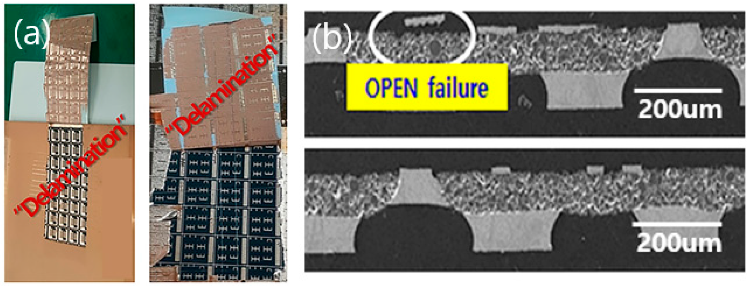
3.2. The Interfacial Adhesion Property and Reliability

Before the reliability evaluation of the two-layer Rt-QFN substrate, the adhesion force evaluation at the interface was performed. This must be verified because it is directly related to human life in semiconductor substrates for vehicles (self-driving and electric vehicles, etc.) requiring high reliability. As a verification and evaluation method, the crosscut peel-off tape test of the resin/Cu seed/Cu plating interface was performed immediately after the copper plating process. In this evaluation method, four types of tape were used through the ASTM D3359 test method [29,30], and up to Tesa#7475 tape, having a strength of 1.2 kgf/cm or more was used. As a result, as shown in Figure 8, both the 5B Level (ASTM D3359 High Level) result and the interfacial adhesion force of 1.2 kgf/cm or more were confirmed at the resin/Cu seed/Cu plating interface, and in the SEM image of Figure 8, the resin and Cu interface Excellent adhesion results were confirmed without peeling between them.
Additionally, in order to verify the interfacial adhesion according to the pretreatment effect, we compared it with the crosscut peel-off tape test under the three conditions of no pretreatment acid, dipping, and LIS pretreatment at the resin/Cu seed layer/Cu plating interface. As shown in Figure 9, 0 kgf/cm in no pretreatment and 1.2 kgf/cm in LIS pretreatment were confirmed. Through this, it was possible to verify the effect of the LIS pretreatment once more [31]. To confirm the high reliability of the two-layer Rt-QFN substrate, we performed a moisture absorption evaluation of the product immediately after copper plating and finally manufactured the product. The moisture absorption evaluation was carried out by maintaining it at 85 °C/85% temperature/humidity condition for 5 h, as shown in Figure 10. As a result, we confirmed that there was no delamination or cracks at the resin/Cu interface in the intermediate and final product. Figure 10 shows the status of the samples after moisture absorption evaluation of the intermediate product and the final finished product and their resultant Cu/resin interface, which was observed through an SEM microscope. Through this, we confirmed that the resin/Cu interface of the two-layer Rt-QFN showed high reliability.

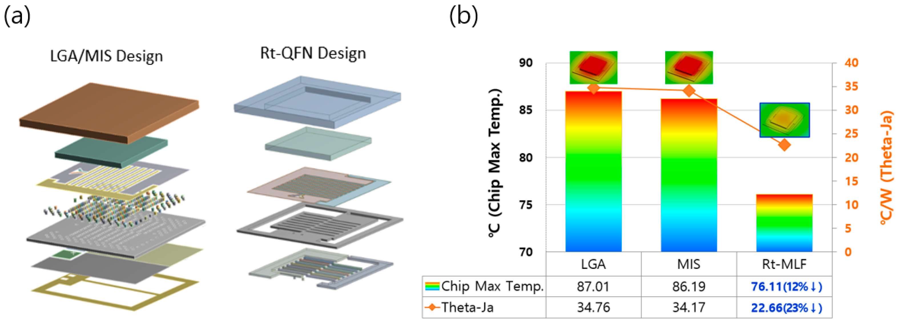
3.3. Thermal Property Analysis with CAE Simulation

In order to evaluate the thermal performance of the two-layer Rt-QFN substrate, a comparative analysis by CAE simulation was performed on the LGA type substrate and the Rt-QFN substrate having almost the same package structure. In the case of the LGA or MIS type substrate, the upper and lower layers are connected through a number of small Cu vias, whereas in the Rt-QFN substrate, both layers are connected through large-area Cu bumps formed by the etching process. The thermal analysis conditions were assumed by applying different thermal conductivity of materials included in each substrate under the conditions of applying the same chip design. The thermal conductivity of EMC, Cu, and resin was applied as 160, 400, and 0.89 W/mK, respectively.
As a result of the CAE simulation, it was confirmed that the thermal resistance of the Rt-QFN substrate was lowered by about 23% compared with the LGA-type substrate, and thus the maximum chip temperature was reduced by about 12%. (Figure 11) This analysis result is presumably due to the structural advantage of the Rt-QFN substrate. In the Rt-QFN substrate, the Cu intermediate layer implemented as a small via hole in the laminated substrate is replaced with a large-area Cu bump so that more heat is expected to be released through the corresponding passage.
As another example of thermal performance evaluation analysis, a thermal performance comparison with AlN ceramic substrate was performed. Similarly, we compared a 65-μm-sized Cu via on a ceramic substrate with a 510-μm-wide Cu bump replaced with a nearly identical structure. The thermal analysis conditions assumed to use a heat source of 0.1 W/mm2 power of the Si chip, and the thermal conductivity of AlN, Cu, and resin were applied as 160, 400, and 0.89 W/mK, respectively. From the analysis results, we were able to confirm the following two things: First, it was confirmed that the AlN substrate and the Rt-QFN substrate showed different types of heat dissipation paths through the heat flux distribution in the cross-sectional view. Second, in the case of the AlN substrate, most of the heat is evenly radiated through the ceramic material, whereas in the Rt-QFN substrate, almost no heat is emitted through the resin with low thermal conductivity and only through the Cu bump. (Figure 12) However, the thermal conductivity of Cu material is superior to that of ceramic material, and in the case of Rt-QFN, since it has a wide area of the thermal path, which is the Cu bump, it leads to almost the same level of heat dissipation performance and, accordingly, it is confirmed that the maximum chip temperature is at a similar level.

4. Summary

Two-layer Rt-QFN substrate technology has been proposed as a new substrate based on the existing lead frame technology, as exhibiting a higher degree of design freedom and excellent thermal dissipation performance and reliability. By introducing a special type of plasma technology and grafting it with sputtering, we were able to maintain high adhesion strength of over 1.2 kgf/cm between the Cu and the resin interface while directly forming a Cu layer on the resin surface without any other adhesion layer, such as Ti, Ni, or Cr. As a result, we were able to confirm the high reliability through moisture absorption evaluation of the final product.
In addition, it was confirmed that the Rt-QFN fabricated using the above technology exhibited structurally excellent heat dissipation characteristics. Rt-QFN substrate showed up to 23% better thermal performance than the laminated substrate under the assumption of implementing a similar design. Furthermore, it was confirmed that it exhibited heat dissipation properties close to the same level as ceramic substrates with excellent heat dissipation properties. It is expected to be used as a substrate for the fields requiring high heat dissipation performance, such as LED applications.

Author Contributions

Investigation, H.-C.K., H.-J.R. and I.-S.B.; Project administration, S.-I.K. and I.-S.B.; Supervision, S.-I.K. and I.-S.B.; Visualization, H.-C.K. and H.-J.R.; Writing—original draft, H.-C.K. and H.-J.R.; Writing—review & editing, I.-S.B. All authors have read and agreed to the published version of the manuscript.

Funding

This research received no external funding.

Institutional Review Board Statement

Not applicable.

Informed Consent Statement

Not applicable.

Data Availability Statement

Data sharing is not applicable to this article.

Acknowledgments

This study was conducted based on joint research and development with the Korea Institute of Materials Science (KIMS) tribology Lab.

Conflicts of Interest

The authors declare no conflict of interest.

References

  1. Lau, J.H. Recent advances and trends in heterogeneous integrations. J. Microelectron. Electron. Packag. 2019, 16, 45–77. [Google Scholar]
  2. Lau, J.H. Recent advances and trends in fan-out wafer/panel-level packaging. J. Electron. Packag. 2019, 141, 040801. [Google Scholar] [CrossRef] [Green Version]
  3. Fujihira, T.; Otsuki, M.; Ikawa, O.; Nishiura, A.; Fujishima, N. The state-of-the-art and future trend of power semiconductor devices. In Proceedings of the PCIM Europe 2015, International Exhibition and Conference for Power Electronics, Intelligent Motion, Renewable Energy and Energy Management, Nuremberg, Germany, 19–20 May 2015; pp. 1–8. [Google Scholar]
  4. Ahmad, A. Automotive semiconductor industry—Trends, safety and security challenges. In Proceedings of the 2020 8th International Conference on Reliability, Infocom Technologies and Optimization, Noida, India, 4–5 June 2020; pp. 1373–1377. [Google Scholar]
  5. Leteinturier, P. Automotive semi-conductor trend & challenges. In Proceedings of the Design Automation & Test. in Europe Conference, Munich, Germany, 6–10 March 2006; p. 1. [Google Scholar]
  6. Abelein, U.; Lochner, H.; Hahn, D.; Straube, S. Complexity, quality and robustness—The challenges of tomorrow’s automotive electronics. In Proceedings of the 2012 Design, Automation & Test in Europe Conference & Exhibition, Dresden, Germany, 12–16 March 2012; pp. 870–871. [Google Scholar]
  7. Chang, N.; Pan, S.; Srinivasan, K.; Feng, Z.; Xia, W.; Pawlak, T.; Geb, D. Emerging ADAS thermal reliability needs and solutions. IEEE Micro. 2018, 38, 66–81. [Google Scholar] [CrossRef]
  8. Johnson, R.; Evans, J.; Jacobsen, P.; Thompson, J.; Christopher, M. The changing automotive environment: High-temperature Electronics. IEEE Trans. Electron. Packag. Manuf. 2004, 27, 164–176. [Google Scholar] [CrossRef]
  9. Pinkos, A.F.; Guo, Y. Automotive design challenges for wide-band-gap devices used in high temperature capable, scalable power vehicle electronics. In Proceedings of the 2013 IEEE Energytech, Cleveland, OH, USA, 21–23 May 2013; pp. 1–5. [Google Scholar]
  10. Yang, Y.; Hefny, M.; Noronha, K.; Callegaro, A.; Goykhman, M.; Baronian, A.; Emadi, A. A fast and accurate thermal-electrical coupled model for SiC traction inverter. In Proceedings of the 2021 IEEE Transportation Electrification Conference & Expo (ITEC), Chicago, IL, USA, 21–25 June 2021; pp. 496–501. [Google Scholar]
  11. Yu, C.; Buttay, C.; Laboure, E. Thermal management and electromagnetic analysis for GaN devices packaging on DBC substrate. Substrate. IEEE Trans. Power Electron. 2017, 32, 906–910. [Google Scholar] [CrossRef] [Green Version]
  12. Manikam, V.R.; Cheong, K.Y. Die Attach materials for high temperature applications: A review. IEEE Trans. Compon. Packag. Manuf. Technol. 2011, 1, 457–478. [Google Scholar] [CrossRef]
  13. Weidner, K.; Kaspar, M.; Seliger, N. Planar interconnect technology for power module system integration. In Proceedings of the 2012 7th International Conference on Integrated Power Electronics Systems (CIPS), Nuremberg, Germany, 6–8 March 2012; pp. 1–5. [Google Scholar]
  14. Locatelli, M.-L.; Khazaka, R.; Diaham, S.; Pham, C.-D.; Bechara, M.; Dinculescu, S.; Bidan, P. Evaluation of encapsulation materials for high-temperature power device packaging. IEEE Trans. Power Electron. 2014, 29, 2281–2288. [Google Scholar] [CrossRef]
  15. HAESUNG DS. Semiconductor Artisan, Products. 2021. Available online: www.haesungds.com (accessed on 1 March 2016).
  16. Lee, K.-H.; Lee, S.-H.; Kang, S.I.; Park, S.-C. Lead Frame and Method for Plating the Same. U.S. Patent Application No. US6469386B1, 22 October 2002. [Google Scholar]
  17. Kang, S.I.; Bae, I.S.; Kim, J.W. Method of Manufacturing Semiconductor Package Substrate and Semiconductor Package Substrate Manufactured Using the Same. U.S. Patent Application No. US10811302B2, 14 February 2020. [Google Scholar]
  18. Bae, I.S.; Kang, S.I. Semiconductor Package Substrate and Method for Manufacturing Same. U.S. Patent Application No. WO2017159954A1, 17 September 2017. [Google Scholar]
  19. Pan, Y.; Liu, Y.; Wang, T.; Lu, X. Effect of a Cu seed layer on electroplated Cu film. Microelectron. Eng. 2013, 105, 18–24. [Google Scholar] [CrossRef]
  20. Woo, T.G.; Park, I.S.; Seol, K.W. Effect of kind and thickness of seed metal on the surface morphology of copper foil. Korean J. Mater. Res. 2007, 17, 283–288. [Google Scholar] [CrossRef]
  21. Lee, S.; Byun, E.-Y.; Kim, J.-K.; Kim, D.-G. Ar and O2 linear ion beam PET treatments using an anode layer ion source. Curr. Appl. Phys. 2014, 14, S180–S182. [Google Scholar] [CrossRef]
  22. Lee, S.; Kim, J.-K.; Kim, D.-G. Effects of electrode geometry on the ion beam extraction of closed drift type anode layer linear ion source. Rev. Sci. Instrum. 2012, 83, 02B703. [Google Scholar] [CrossRef] [PubMed]
  23. Choi, Y.; Kim, T.-G.; Han, J.; Min, B.-K.; Kim, Y.-J.; Lee, S.J. Design and fabrication of multi-aperture plate for multi-ion beam patterning system. Jpn. J. Appl. Phys. 2010, 49, 06GE06. [Google Scholar] [CrossRef]
  24. Jiang, X.; Ji, Q.; Chang, A.; Leung, K.N. Mini rf-driven ion sources for focused ion beam systems. Rev. Sci. Instrum. 2003, 74, 2288–2292. [Google Scholar] [CrossRef]
  25. Hahto, S.K.; Hahto, S.T.; Ji, Q.; Leung, K.N.; Wilde, S.; Foley, E.L.; Grisham, L.R.; Levinton, F.M. Multicusp ion source with external rf antenna for production of protons. Rev. Sci. Instrum. 2004, 75, 355–359. [Google Scholar] [CrossRef] [Green Version]
  26. Lee, Y.; Gough, R.A.; Kunkel, W.B.; Leung, K.N.; Perkins, L.T.; Pickard, D.S.; Sun, L.; Vujic, J.; Williams, M.D.; Wutte, D. Ion energy spread and current measurements of the rf-driven multicusp ion source. Rev. Sci. Instrum. 1997, 68, 1398–1402. [Google Scholar] [CrossRef]
  27. Lieberman, M.A.; Lichtenberg, A.J. Principles of Plasma Discharges and Materials Processing; Wiley-Interscience: Hoboken, NJ, USA, 1994. [Google Scholar]
  28. Volkert, C.A.; Minor, A.M. Introductory article: Focused ion beam microscopy and micromachining. MRS Bull. 2007, 32, 389–399. [Google Scholar] [CrossRef] [Green Version]
  29. Rezaee, M.; Tsai, L.C.; Haider, M.I.; Yazdi, A.; Sanatizadeh, E.; Salowitz, N.P. Quantitative peel test for thin films/layers based on a coupled parametric and statistical study. Sci. Rep. 2019, 9, 19805. [Google Scholar] [CrossRef] [PubMed]
  30. Miloš, D.; Jaroslav, L.; Silvia, R.; Zuzana, S.; Piero, T.; Jaroslav, V. Standardization of peeling tests for assessing the cohesion and consolidation characteristics of historic stone surfaces. Mater. Struct. 2011, 45, 505–520. [Google Scholar]
  31. Lee, S.W.; Kim, J.B.; Lee, C.M. Effects of plasma cleaning of the Cu seed layer surface on Cu electroplating. J. Korean Phys. Soc. 2001, 39, S472–S477. [Google Scholar]
Figure 1. Schematic diagram of two-layer Rt-QFN Manufacturing Process.
Coatings 12 00612 g001
Figure 2. Example of Cu layer peeling failure: (a) Delamination of Cu layer on resin surface; (b) SEM image for the resulting open failure.
Coatings 12 00612 g002
Figure 3. HDS Cu sputtering process w/plasma pretreatment to secure high adhesion.
Coatings 12 00612 g003
Figure 4. Current density profile of HDS LIS module.
Coatings 12 00612 g004
Figure 5. Cu layer flatness before (left) and after (right) Cu plating improvement.
Coatings 12 00612 g005
Figure 6. Cu thickness uniformity after Cu plating process.
Coatings 12 00612 g006
Figure 7. Surface roughness profile of Cu plating layer in two-layer Rt-QFN.
Coatings 12 00612 g007
Figure 8. Adhesive strength evaluation method: (a) Example photo of Crosscut test; (b) SEM microscope between resin and Cu interface.
Coatings 12 00612 g008
Figure 9. Effect of plasma treatment on adhesion strength between resin and Cu interface.
Coatings 12 00612 g009
Figure 10. Moisture absorption evaluation of two-layer Rt-QFN: (a) Peel off tape test after moisture absorption; (b) SEM image of the interface between resin and Cu.
Coatings 12 00612 g010
Figure 11. Comparison of heat dissipation performance between LGA and Rt-QFN substrate: (a) Structure of LGA/MIS substrate and Rt-QFN substrate; (b) Heat dissipation performance.
Coatings 12 00612 g011
Figure 12. Comparison of heat dissipation performance between Ceramic and Rt-QFN substrate: (a) AlN Substrate; (b) Rt-QFN Substrate.
Coatings 12 00612 g012
Publisher’s Note: MDPI stays neutral with regard to jurisdictional claims in published maps and institutional affiliations.

