
A Study on Functional Hydrophobic Stainless Steel 316L Using Single-Step Anodization and a Self-Assembled Monolayer Coating to Improve Corrosion Resistance


Abstract
:1. Introduction
2. Materials and Methods
3. Results and Discussion
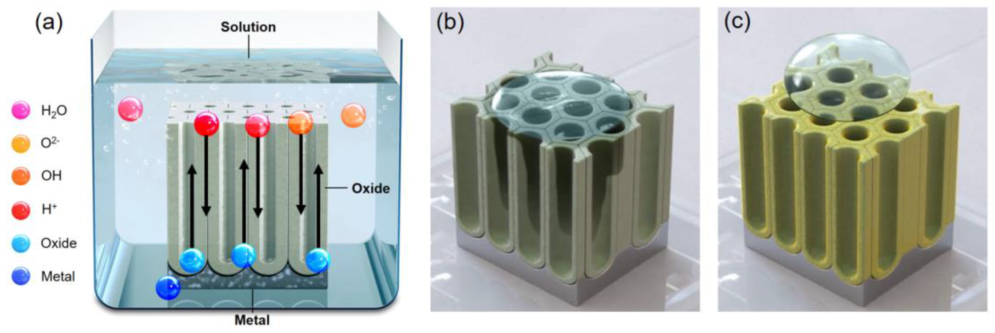
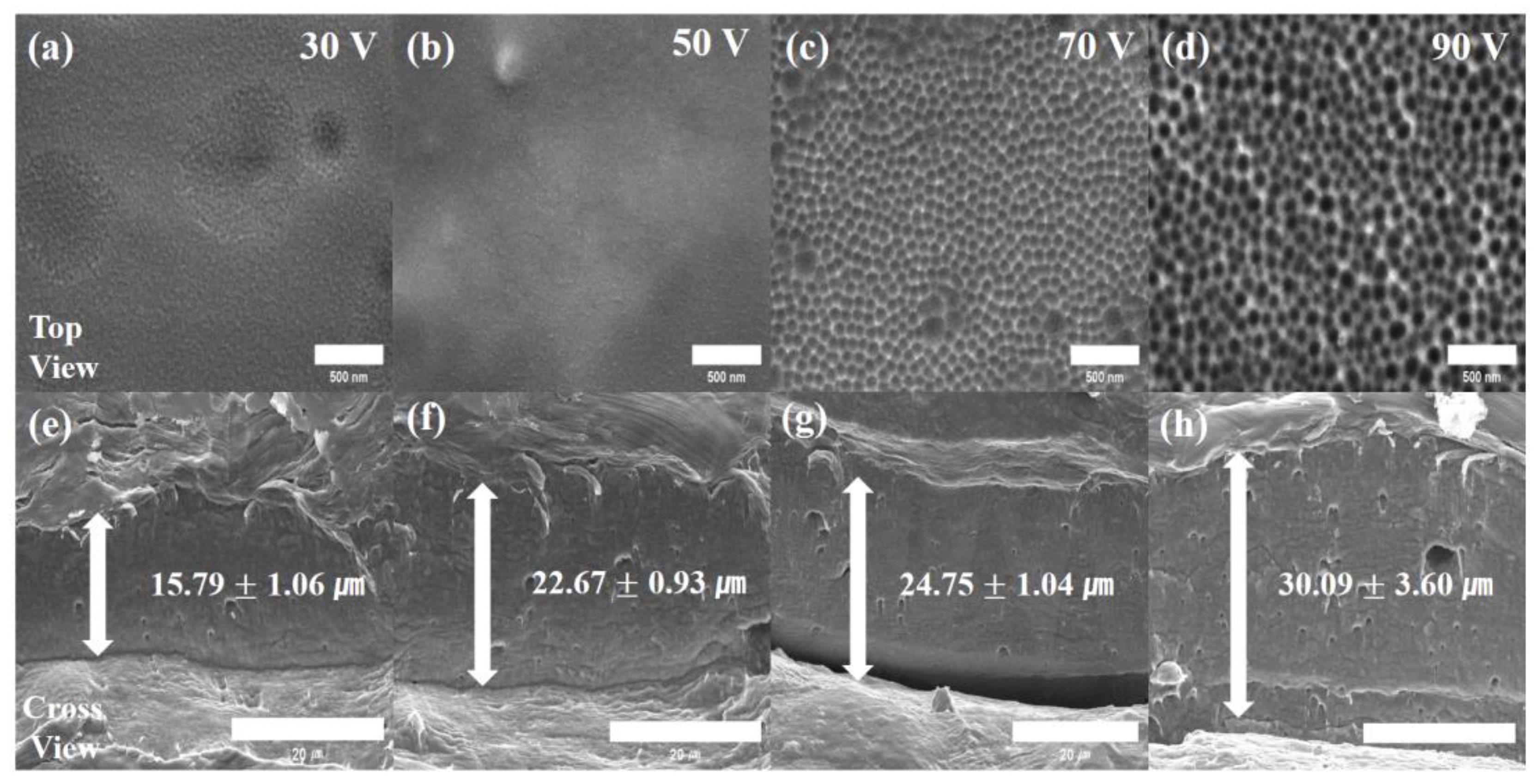
3.1. Fabrication Stainless Steel Anodizing
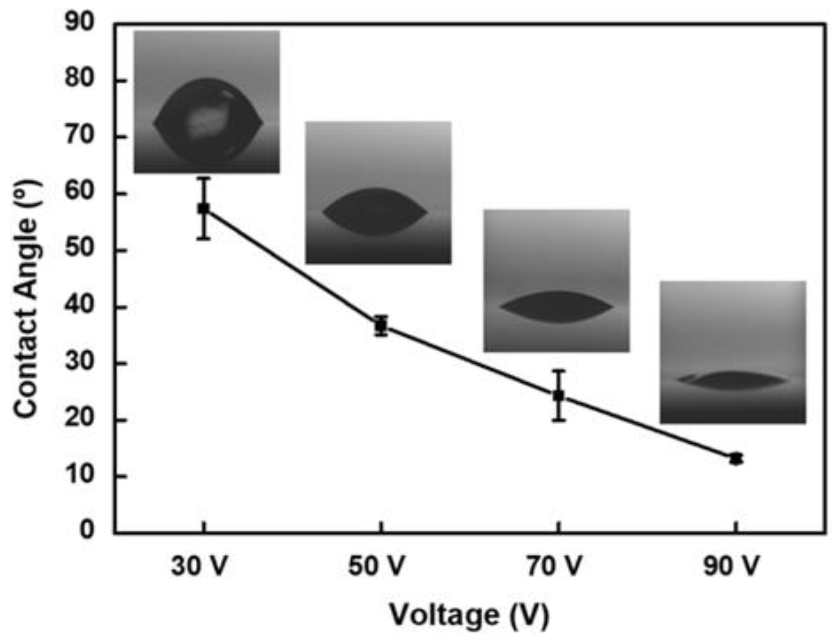
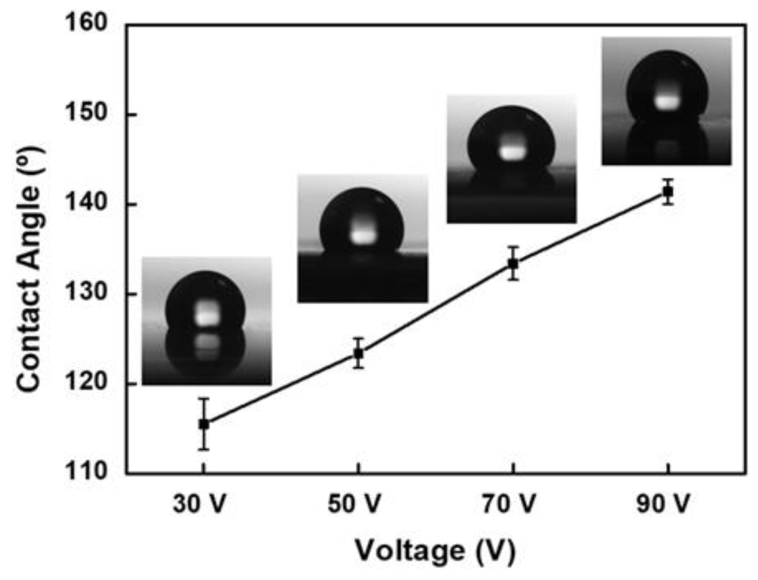
3.2. Characterization of Wettability
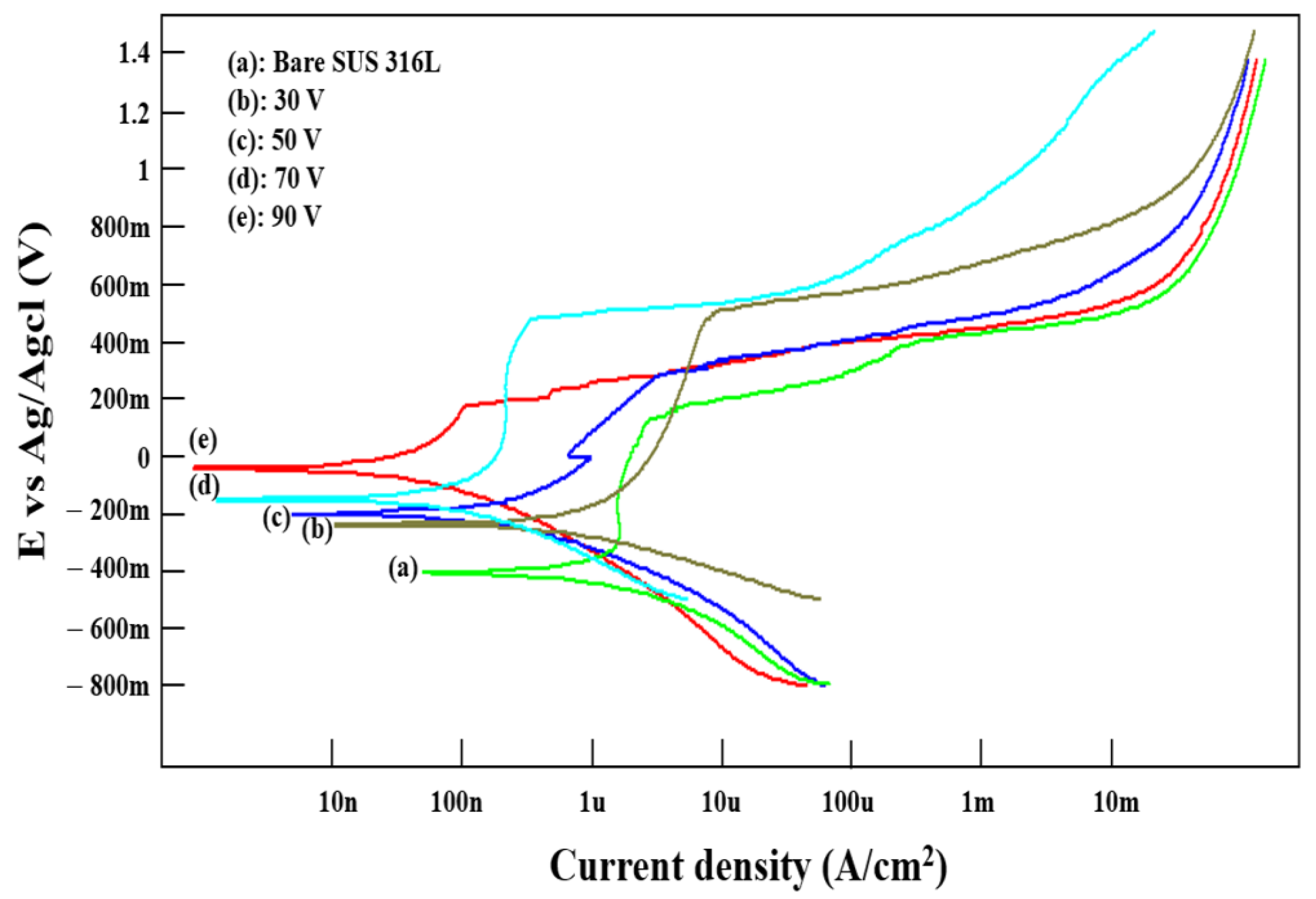
3.3. Analysis of Potentiodynamic Polarization
4. Conclusions
Funding
Institutional Review Board Statement
Informed Consent Statement
Data Availability Statement
Conflicts of Interest
References
- Cai, Y.; Chang, W.; Luo, X.; Sousa, A.M.; Lau, K.H.A.; Qin, Y. Superhydrophobic structures on 316L stainless steel surfaces machined by nanosecond pulsed laser. Precis. Eng. 2018, 52, 266–275. [Google Scholar] [CrossRef] [Green Version]
- Klimas, V.; Pakstas, V.; Vrublevsky, I.; Chernyakova, K.; Jagminas, A. Fabrication and Characterization of Anodic Films onto the Type-304 Stainless Steel in Glycerol Electrolyte. J. Phys. Chem. C 2013, 117, 20730–20737. [Google Scholar] [CrossRef]
- Lee, C.; Kim, J. Surface Modification Method of Stainless Steel using Electrochemical Etching. J. Korean Soc. Precis. Eng. 2014, 31, 353–358. [Google Scholar] [CrossRef]
- Metroke, T.L.; Parkhill, R.L.; Knobbe, E.T. Passivation of metal alloys using sol–gel-derived materials—A review. Prog. Org. Coat. 2001, 41, 233–238. [Google Scholar] [CrossRef]
- Zhilei, C.; Maobing, S.; Lida, W. Cathodic etching for fabrication of super-hydrophobic aluminum coating with micro/nano-hierarchical structure. J. Solid State Electrochem. 2013, 17, 2661–2669. [Google Scholar] [CrossRef]
- Feng, L.; Che, Y.; Liu, Y.; Qiang, X.; Wang, Y. Fabrication of superhydrophobic aluminium alloy surface with excellent corrosion resistance by a facile and environment-friendly method. Appl. Surf. Sci. 2013, 283, 367–374. [Google Scholar] [CrossRef]
- Vazirinasab, E.; Jafari, R.; Momen, G. Application of superhydrophobic coatings as a corrosion barrier: A review. Surf. Coat. Technol. 2018, 341, 40–56. [Google Scholar] [CrossRef]
- Zhang, F.; Zhao, L.; Chen, H.; Xu, S.; Evans, D.G.; Duan, X. Corrosion Resistance of Superhydrophobic Layered Double Hydroxide Films on Aluminum. Angew. Chem. 2008, 120, 2500–2503. [Google Scholar] [CrossRef]
- Cao, L.; Jones, A.K.; Sikka, V.K.; Wu, J.; Gao, D. Anti-icing superhydrophobic coatings. Langmuir 2009, 25, 12444–12448. [Google Scholar] [CrossRef]
- Sarshar, M.A.; Swarctz, C.; Hunter., S.; Simpson., J.; Choi., C.-H. Self-cleaning surfaces—Virtual realities. Nat. Mater. 2003, 2, 301–306. [Google Scholar]
- Lim, H.E.; Park, J.S.; Kim, W.D. Micro/nanostructured Superhydrophobic Surface. Elastomers Compos. 2009, 44, 244. [Google Scholar]
- Kalin, M.; Polajnar, M.J.T.I. The correlation between the surface energy, the contact angle and the spreading parameter, and their relevance for the wetting behaviour of DLC with lubricating oils. Tribol. Int. 2013, 66, 225–233. [Google Scholar] [CrossRef]
- Song, D.; Lian, B.; Fu, Y.; Wang, G.; Qiao, Y.; Klu, E.E.; Gong, X.; Jiang, J. Dual-Layer Corrosion-Resistant Conversion Coatings on Mg-9Li Alloy via Hydrothermal Synthesis in Deionized Water. Metals 2021, 11, 1396. [Google Scholar] [CrossRef]
- Jeong, C.; Choi, C.H. Single-step direct fabrication of pillar-on-pore hybrid nanostructures in anodizing aluminum for superior superhydrophobic efficiency. ACS Appl. Mater. Interfaces 2012, 4, 842–848. [Google Scholar] [CrossRef] [PubMed]
- Yerokhin, A.L.; Snizhko, L.O.; Gurevina, N.L.; Leyland, A.; Pilkington, A.; Matthews, A. Discharge characterization in plasma electrolytic oxidation of aluminium. Appl. Phys. 2003, 36, 2110. [Google Scholar] [CrossRef]
- Wang, Z.; Li, Q.; She, Z.; Chen, F.; Li, L. Low-cost and large-scale fabrication method for an environmentally-friendly superhydrophobic coating on magnesium alloy. J. Mater. Chem. 2012, 22, 4097. [Google Scholar] [CrossRef]
- Boinovich, L.B.; Emelyanenko, A.M.; Modestov, A.D.; Domantovsky, A.G.; Emelyanenko, K.A. Synergistic Effect of Superhydrophobicity and Oxidized Layers on Corrosion Resistance of Aluminum Alloy Surface Textured by Nanosecond Laser Treatment. ACS Appl. Mater. Interfaces 2015, 7, 19500–19508. [Google Scholar] [CrossRef] [PubMed] [Green Version]
- Xu, Q.F.; Wang, J.N.; Sanderson, K.D. A general approach for superhydrophobic coating with strong adhesion strength. J. Mater. Chem. 2010, 20, 5961. [Google Scholar] [CrossRef]
- Lee, W.; Nielsch, K.; Gösele, U. Self-ordering behavior of nanoporous anodic aluminum oxide (AAO) in malonic acid anodization. Nanotechnology 2007, 18, 8. [Google Scholar] [CrossRef] [Green Version]
- Lee, W.; Ji, R.; Gösele, U.; Nielsch, K. Fast fabrication of long-range ordered porous alumina membranes by hard anodization. Nat. Mater. 2006, 5, 741–747. [Google Scholar] [CrossRef]
- Lee, W.; Scholz, R.; Gösele, U. A continuous process for structurally well-defined Al2O3 nanotubes based on pulse anodization of aluminum. Nano Lett. 2008, 8, 2155–2160. [Google Scholar] [CrossRef] [PubMed] [Green Version]
- Nosonovsky, M.; Bhushan, B. Biomimetic superhydrophobic surfaces: Multiscale approach. Nano Lett. 2007, 7, 2633–2637. [Google Scholar] [CrossRef] [PubMed]
- Chen, Y.; Zhang, Y.; Shi, L.; Li, J.; Xin, Y.; Yang, T.; Guo, Z. Transparent superhydrophobic/superhydrophilic coatings for self-cleaning and anti-fogging. Appl. Phys. Lett. 2012, 101, 033701. [Google Scholar] [CrossRef]
- Jeong, C. Nano-Engineering of Superhydrophobic Aluminum Surfaces for Anti-Corrosion. Ph.D. Thesis, Stevens Institute of Technology, Hoboken, NJ, USA, 2013. [Google Scholar]
- Hassan, A.; Ali, G.; Park, Y.J.; Hussain, A.; Cho, S.O. Formation of a self-organized nanoporous structure with open-top morphology on 304L austenitic stainless steel. Nanotechnology 2020, 31, 315603. [Google Scholar] [CrossRef] [PubMed]
- Ji, H.; Jeong, C. Fabrication of Superhydrophobic Aluminum Alloy Surface with Hierarchical Pore Nanostructure for Anti-Corrosion. Corros. Sci. Technol. 2019, 18, 228. [Google Scholar]
- Jeong, C.; Ji, H. Systematic Control of Anodic Aluminum Oxide Nanostructures for Enhancing the Superhydrophobicity of 5052 Aluminum Alloy. Materials 2019, 12, 3231. [Google Scholar] [CrossRef] [PubMed] [Green Version]
- Wang, Z.; Paschalidou, E.; Seyeux, A.; Zanna, S.; Maurice, V.; Marcus, P. Mechanisms of Cr and Mo Enrichments in the Passive Oxide Film on 316L Austenitic Stainless Steel. Front. Mater. 2019, 6, 232. [Google Scholar] [CrossRef] [Green Version]
- Park, E.J.; Cho, Y.K.; Kim, D.H.; Jeong, M.G.; Kim, Y.H.; Kim, Y.D. Hydrophobic polydimethylsiloxane (PDMS) coating of mesoporous silica and its use as a preconcentrating agent of gas analytes. Langmuir 2014, 30, 10256–10262. [Google Scholar] [CrossRef]
- Jeong, C.; Lee, J.; Sheppard, K.; Choi, C.H. Air-Impregnated Nanoporous Anodic Aluminum Oxide Layers for Enhancing the Corrosion Resistance of Aluminum. Langmuir 2015, 31, 11040–11050. [Google Scholar] [CrossRef]
- Hu, P.; Xie, Q.; Ma, C.; Zhang, G. Silicone-Based Fouling-Release Coatings for Marine Antifouling. Langmuir 2020, 36, 2170–2183. [Google Scholar] [CrossRef] [Green Version]
- Wang, H.; Shuro, I.; Umemoto, M.; Ho-Hung, K.; Todaka, Y. Annealing behavior of nano-crystalline austenitic SUS316L produced by HPT. Mater. Sci. Eng. A 2012, 556, 906–910. [Google Scholar] [CrossRef]
- Cai, Q.; Paulose, M.; Varghese, O.K.; Grimes, C.A. The Effect of Electrolyte Composition on the Fabrication of Self-Organized Titanium Oxide Nanotube Arrays by Anodic Oxidation. J. Mater. Res. 2005, 20, 230–236. [Google Scholar] [CrossRef]
- Jani, A.M.; Losic, D.; Voelcker, N.H. Nanoporous anodic aluminium oxide: Advances in surface engineering and emerging applications. Prog. Mater. Sci. 2013, 58, 636–704. [Google Scholar] [CrossRef]
- Park, Y.; Jeong, C. Study on a Superhydrophobic Stainless Steel (SUS 304) Surface to Enhance Corrosion Resistance. Korean J. Met. Mater. 2021, 59, 217–222. [Google Scholar] [CrossRef]
- Kim, S.H.; Jeong, C. Feasibility of Machine Learning Algorithms for Predicting the Deformation of Anodic Titanium Films by Modulating Anodization Processes. Materials 2021, 14, 1089. [Google Scholar] [CrossRef] [PubMed]
- Cassie, A.; Baxter, S. Wettability of porous surfaces. Trans. Faraday Soc. 1944, 40, 546. [Google Scholar] [CrossRef]
- Jeong, C.; Choi, C.H. Google Patents. 2014. Available online: http://google.com/patent/US20140255682A1/en (accessed on 11 September 2014).
- Lee, W. The anodization of aluminum for nanotechnology applications. JOM 2010, 62, 57–63. [Google Scholar] [CrossRef]
- Song, H.; Kim, M.; Jung, G.; Vang, M.; Park, Y. The effects of spark anodizing treatment of pure titanium metals and titanium alloys on corrosion characteristics. Surf. Coat. Technol. 2007, 201, 8738–8745. [Google Scholar] [CrossRef]


| C | Mn | P | S | Ni | Cr | Mo | Fe | |
|---|---|---|---|---|---|---|---|---|
| SUS 316L | 0.03 | 2.00 | 0.45 | 0.03 | 12.0–15.0 | 16.0–18.0 | 2.0–3.0 | Bal. |
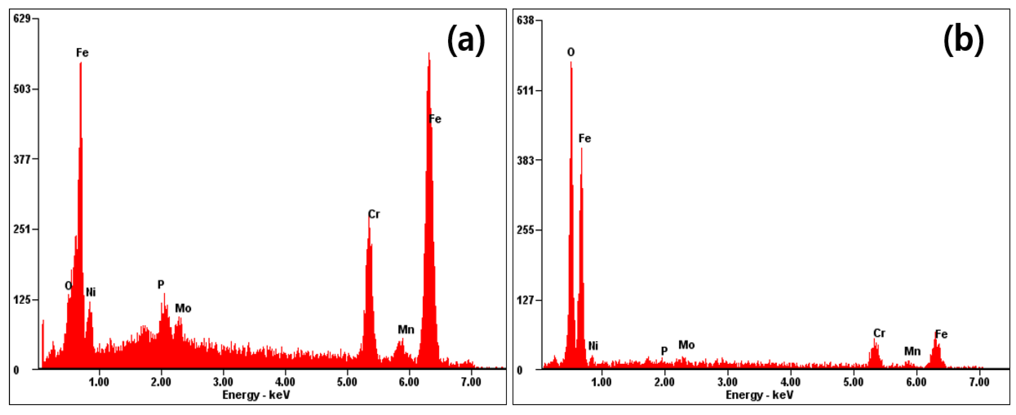
| Sample | Elements (at%) | ||||||
|---|---|---|---|---|---|---|---|
| O | Ni | P | Mo | Cr | Mn | Fe | |
| SUS 316L | 10.87 | 11.99 | 2.83 | 1.54 | 16.25 | 3.17 | 53.35 |
| SUS 316L Anodized | 75.17 | 2.62 | 0.16 | 0.81 | 7.12 | 1.41 | 12.71 |
| DP (nm) | Dint (nm) | Solid Fraction | |
|---|---|---|---|
| 30 V | Not available | Not available | Not available |
| 50 V | Not available | Not available | Not available |
| 70 V | 68.62 ± 8.07 | 89.78 ± 8.30 | 0.4559 |
| 90 V | 92.17 ± 8.25 | 106.45 ± 7.22 | 0.3201 |
| Anodization | Anodization + Coating | |
|---|---|---|
| 30 V | 57.4° ± 5.36° | 115.5° ± 2.85° |
| 50 V | 36.7° ± 1.59° | 123.4° ± 1.63° |
| 70 V | 24.3° ± 4.36° | 133.4° ± 1.82° |
| 90 V | 13.2° ± 0.60° | 141.4° ± 1.37° |
| Samples | Ecorr (mV) | Icorr (A/cm2) | IE (%) |
|---|---|---|---|
| SUS 316L | −404.2 ± 5.84 | 2.36 ± 0.13 × 10⁻⁷ | 0 |
| 30 V anodized | −232.2 ± 3.18 | 1.67 ± 0.2 × 10⁻⁷ | 29.23 |
| 50 V anodized | −192.4 ± 3.61 | 1.16 ± 0.17 × 10⁻⁷ | 50.84 |
| 70 V anodized | −144.6 ± 1.62 | 2.49 ± 0.12 × 10⁻⁸ | 89.44 |
| 90 V anodized | −38.3 ± 4.61 | 9.02 ± 0.36 × 10⁻⁹ | 96.18 |
Publisher’s Note: MDPI stays neutral with regard to jurisdictional claims in published maps and institutional affiliations. |
© 2022 by the author. Licensee MDPI, Basel, Switzerland. This article is an open access article distributed under the terms and conditions of the Creative Commons Attribution (CC BY) license (https://creativecommons.org/licenses/by/4.0/).
Share and Cite
Jeong, C. A Study on Functional Hydrophobic Stainless Steel 316L Using Single-Step Anodization and a Self-Assembled Monolayer Coating to Improve Corrosion Resistance. Coatings 2022, 12, 395. https://doi.org/10.3390/coatings12030395
Jeong C. A Study on Functional Hydrophobic Stainless Steel 316L Using Single-Step Anodization and a Self-Assembled Monolayer Coating to Improve Corrosion Resistance. Coatings. 2022; 12(3):395. https://doi.org/10.3390/coatings12030395
Chicago/Turabian StyleJeong, Chanyoung. 2022. "A Study on Functional Hydrophobic Stainless Steel 316L Using Single-Step Anodization and a Self-Assembled Monolayer Coating to Improve Corrosion Resistance" Coatings 12, no. 3: 395. https://doi.org/10.3390/coatings12030395