Article

Properties of Different Waterproof Bonding Layer Systems for Cement Concrete Bridge Deck Pavement

1
School of Highway, Chang’an University, Xi’an 710064, China
2
Shandong Transportation Institute, Jinan 250002, China
*
Author to whom correspondence should be addressed.
Coatings 2022, 12(3), 308; https://doi.org/10.3390/coatings12030308
Submission received: 25 December 2021 / Revised: 11 February 2022 / Accepted: 21 February 2022 / Published: 24 February 2022
(This article belongs to the Special Issue Asphalt Pavement Materials and Surface)

Abstract

:
The performance of waterproof bonding layer systems significantly affects the service life of concrete bridge deck pavement. This article aims to compare the bonding properties and composite structure mechanical properties of different waterproof bonding layer systems in bridge deck pavement to recommend appropriate structures based on service conditions. To fulfill this objective, four kinds of waterproof bonding material composite systems were designed, and test samples were fabricated. Then, the waterproof bonding layer properties were studied by penetration resistance tests, scalding resistance tests, and corrosion resistance tests. Pull-off tests were conducted to compare the bonding properties. Then, dynamic modulus tests, Hamburg wheel tracking tests, and static load creep tests of composite structure specimens were implemented to evaluate the dynamic and static mechanical performances and water-temperature stability. The findings showed that the four schemes had good impermeability. The pull-off strengths of scheme III at 25 °C were about 2.5-, 2.5-, and 4-times those of schemes I, II, and IV, respectively, and the pull-off strengths at 50 °C were about 1.6-, 2-, and 1.6-times those of schemes I, II, and IV, respectively, and the bonding performances and dynamic modulus of different schemes were ranked as follows: III > I > II > IV. The results of the Hamburg wheel tracking test were consistent with the static load creep test. The high-temperature stability of scheme IV was the best, while the stabilities of scheme III and I were better than that of scheme II. In conclusion, the scheme of concrete bridge deck pavement can be selected based on the environmental conditions and traffic load, and schemes III and I should be considered first. The findings of this research could provide technical support for the future design of bridge deck waterproof bonding systems.

1. Introduction

With increasing traffic volumes and axle loads and increasingly harsh weather conditions, serious early disease appears on bridge deck pavement, which significantly affects the function of expressways and induces traffic accidents [1,2,3,4,5]. The performance differences between asphalt concrete and cement concrete are significant, so the interface is often considered to be vulnerable zone. There will inevitably be an insufficient bond strength between the interlayer if there are no waterproof bonding layers between the asphalt concrete and the cement concrete. This will cause delamination, rutting, cracking, and other diseases on the bridge deck pavement, which will affect the safety of traffic [6,7,8]. According to the research and analysis of multi objective grey target decision theory, some scholars have obtained the priority relationship among shear performance, bond performance, and cost [9]. Therefore, this paper mainly analyzes the four schemes from the bonding properties and composite structure mechanical properties.
To strengthen the overall bonding performance of the bridge deck and pavement materials, a considerable amount of research has been conducted on the performances of waterproof bonding materials around the world [10,11,12,13,14,15,16,17,18]. Large numbers of investigations have shown that the bonding effect of the waterproof system under low and normal temperatures is the main factor affecting the layer performance. Under high temperatures, the working temperature of the bridge deck is close to or even reaches the softening point of the asphalt-based waterproof material. Therefore, during the construction process, the rolling action of the roller and the high temperature generated during paving will cause the waterproof layer to fail to varying degrees [19,20,21,22]. Kruntcheva et al. [23] showed that the type of contact between the layers has a significant influence on the performance of the interface through dynamic and static tests. It is recommended to introduce vertical and horizontal shear response modulus to describe the stiffness and strength of the waterproof bonding layer. Xu et al. [24] used laboratory direct shear and pull-out tests to test the interface bonding strength of the waterproof bonding layer. Guo et al. [25,26] selected three different waterproof bonding layers to do waterproof and shear strength tests, and the results showed that SBS-modified asphalt was better. Zhang et al. [27] found that modified asphalt had the highest bonding strength to concrete slabs through experiments, followed by ordinary asphalt and then emulsified asphalt. Guo et al. [28] studied the influence of factors such as the drawing rate, roughness, thickness, temperature, and humidity on the drawing strength and shear strength of waterproof bonding layers. The research results showed that the construction quality of the waterproof bond system was greatly affected by temperature and humidity. The construction temperature should be 25 °C, and the relative humidity should not exceed 60%. Zhang et al. [10] analyzed the interlaminar performance of waterproof and cohesive materials for concrete bridge deck via oblique shear tests, pull-off tests, and shear tests after loading under specific test conditions. The results showed that the order of the shear failure life of the selected waterproof and cohesive materials is SBS-modified asphalt were superior to those of asphalt rubber (19%). For the bridge deck paving–waterproof bonding layer, not only the performance of the waterproof adhesive material itself needs to be tested, but the composite structure of the bridge deck paving system also needs to be tested and evaluated, which will help to determine the overall anti-destructive ability of the pavement. Ai et al. [29] carried out a direct tensile, direct shear, and 45-degree skew shear tests at different temperatures (0, 25, and 70 °C) on specimens to compare the bonding properties of different waterproof bonding material composites. The results showed that the composite specimens with the best direct tensile strength and fatigue life used CILBOND®55C as the upper bonding materials and CILBOND®62 W as the lower bonding materials. Qiu et al. [9] used a waterproof bonding system consisting of two layers, a waterproof layer and a bonding layer, to ensure that the deck pavement and the steel panel could form a monolithic structure. They conducted a series of laboratory experiments that demonstrated that applying a waterproof bonding system improved the fatigue life of the bridge deck pavement significantly.
In summary, there are many types of waterproof bonding layers on the market at present. Although there have been a large number of experiments to detect the waterproof bonding layer [30,31,32,33,34,35], most of the relevant research has focused on optimizing a specific aspect of its performance, such as its shear strength or fatigue performance. Waterproof bonding layers have different influences on the upper paving structure, so the whole bridge deck pavement system’s mechanical properties and temperature stability are changed. However, the previous research on the properties of different cement concrete bridge deck pavement waterproof bonding layer systems was not comprehensive, which limits the structural design of waterproof bonding layer of concrete bridge deck. Therefore, four commonly used cement concrete bridge-deck waterproof-bonding-material composite systems were designed and evaluated comprehensively in this paper, and the research framework is shown in Figure 1. The waterproof bonding layer properties were studied by impermeability tests, scalding resistance tests, and corrosion resistance tests. The interface bonding performances were studied by pull-out tests at two different test temperatures (25 and 50 °C). The properties of the composite bridge deck pavement structure were tested by Hamburg wheel track tests, dynamic modulus tests, and static load creep tests. Based on this study, the scheme of concrete bridge deck pavement can be selected based on the environmental conditions and traffic load, which is of great significance for the structure design of cement concrete bridge deck pavement.

2. Experiment Program

2.1. Materials and Methods

In order to compare the bonding properties and composite structure mechanical properties of different waterproof bonding layer systems of bridge deck pavement, a deep research study was conducted. Firstly, the four waterproof bonding layers and composite bridge deck pavement schemes were designed. Secondly, the preparation of waterproof bonding layer and the technical indices of component materials were introduced. Then, the four composite bridge deck pavement specimens were prepared based on the cement prefabricated slabs with dimensions of 32 cm × 26 cm. The details are described in the following chapter.

2.1.1. Structure Design of Bridge Deck Pavement

The four commonly used waterproof bonding layers and composite bridge deck pavement schemes were designed and are shown in Table 1. About 10 kinds of materials were examined, including styrene–butadiene–styrene (SBS) modified asphalt, modified emulsified asphalt, and protective board. Asphalt sand (AC–5), pouring asphalt concrete (GA–10), and stone matrix asphalt (SMA–13) were used in the different schemes, the aggregate gradation of the three mixtures is shown in Table 2. The technical indexes of AC-5, SMA-13 meet the requirements of JTG F40-2004, technical indexes of GA-5 comply with standard technical regulations of “Design and Construction of Pavement on Highway Steel Deck Bridge” (JTG/T 3364-02-2019).

2.1.2. Preparation of Waterproof Bonding Layer

(1) Scheme I
First, the SBS-modified asphalt was sprayed with the amount of 1.2 L/m2. Second, a layer with a thickness of 5–10 mm was spread with 3–5‰ asphalt ready-mixed crushed stone added. Third, when the sealing layer was complete, the AC–5 mixture was constructed by a linear rubbing test machine. Finally, the SBS–modified emulsified asphalt bonding layer was sprayed with a distribution amount of 1.0 kg/m2.
The technical indices of the SBS–modified asphalt complied with the requirements of the I–D standard JTG F40–2004. The modified emulsified asphalt met the technical requirements of the specifications of JTG–2004.
(2) Scheme II
First, rubber asphalt was coated with a controlled thickness of 5 mm. The rubber asphalt was different from the conventional rubber asphalt, which was processed through the composite modification process and had a high elasticity, viscosity, and toughness [36]. The test indices of rubber asphalt are shown in Table 3.
The protective plate impregnated with asphalt was placed, which mainly protected the rubber asphalt. The protective plate with the size of 30 mm × 30 mm × 4 mm was used in the laboratory. Finally, the modified emulsified asphalt bonding layer was sprayed with a distribution of 1.0 kg/m2.
(3) Scheme III
The waterproof bonding layer was mainly composed of a GIS–I solvent-based adhesive coating and GA–10 waterproof layer. The GIS–I was coated first and then the GA–10 was constructed. The pouring asphalt concrete had a small porosity and a good waterproofing function. Due to the high asphalt content, it exhibited excellent interface contact performances. The GIS–I solvent-based adhesive was a single-component solvent-based waterproof adhesive formed by melting asphalt and a variety of polymer-resin-based additives in organic solvents through special processing technology. Table 4 shows the drying and curing times of the GIS–I adhesive at different temperatures.
(4) Scheme IV
The waterproof bonding layer was a mechanically sprayed waterproof coating film. Different from the conventional flexible waterproof film, a polymer-modified asphalt waterproof coating was sprayed as five layers, and alkali-free glass was sprayed simultaneously when spraying the 2nd and 4th layers were completed. The technical indicators of the bridge deck bonding waterproof coating are shown in Table 5. The fiber that was sprayed simultaneously with the waterproof coating was alkali-free glass-fiber non-twisted coarse-sand-glass type-E fiber, with a single-fiber diameter of 13 μm and the technical indicators shown in Table 6.

2.1.3. Preparation of Bridge Deck Pavement Specimens

For the specimen preparation, the following steps were taken:
  • The cement prefabricated slabs with dimensions of 32 cm × 26 cm were prepared. To approximate the actual site conditions, the bridge-cement concrete-box-girder construction ratio and materials were used, which were formed and cured simultaneously. The box girder was cured for 28 days to meet the strength requirements. Then, cutting and surface grinding were carried out successively to remove the laitance on the surface and increase the surface roughness, as shown in Figure 2.
  • The four waterproof bonding layers and composite bridge deck pavement structures were constructed on the bridge deck according to schemes I–IV. The four bridge deck pavement specimens are shown in Figure 3.
  • According to the demands of the test, the bridge deck pavement specimens could be cut or drilled with a specific size. Figure 4 shows the drilling of cylindrical specimens.

2.2. Basic Performance Tests Method

2.2.1. Waterproof Bonding Layer Property Tests

(1) Impermeability Test
The composite specimens composed of cement concrete, asphalt mixture, and four kinds of waterproof and cohesive materials were formed. The impermeability was tested according to the regulations of “Standard Test Methods of Bitumen and Bituminous Mixtures for Highway Engineering” (JTG E20–2011) T 0730–2011. The impermeability test of a composite specimen was carried out by using the material permeameter for the structural layer, which is shown in Figure 5. The number of replicates was no less than three. The material permeameter for the structural layer was composed of a barometer, a pressure cylinder with a plate, a clamping bolt, and a base [37]. The water seepage on the side of the rutting plate was observed, and the starting time of the water seepage was recorded.
(2) Scalding resistance test
This scalding resistance test refers to “Standard Test Methods of Bitumen and Bituminous Mixtures for Highway Engineering” (JTG E20–2011) T 0755–2011. This test mainly verified whether the crack resistance of each waterproof layer material decreased or if the layer lost its waterproof effect after the surface layer was constructed. A release agent was coated on a glass plate, and the waterproof layer film was completely peeled off after forming. The waterproof layer film was covered with a cement concrete slab, and the asphalt mixture was overlaid via rotary compaction or rolling with a Hamburg linear kneading machine. The temperature was the on-site construction control temperature. After simulating the on-site rolling and forming, it was determined whether the bottom of the waterproof membrane was damaged.
(3) Corrosion resistance test
Corrosion resistance test refers to “Corrosion tests in artificial atmospheres. Salt spray tests” (GB/T 10125–2012). The purpose of this experiment was to qualitatively simulate the durability, corrosion resistance, and protection of the bridge deck when chlorine salt seeped into the waterproof layer with water after repeated high-temperature and low-temperature cycles [38]. The specimens were obtained by cutting the bridge deck pavement specimens with dimensions of 10 mm × 30 mm × 10 mm. There were three replicates for every scheme. Figure 6 shows the device for simulating chloride penetration into the waterproof layer specimens.
The test procedures were as follows:
  • When the specimen is formed, it was vacuumed and immersed in water at room temperature for 7 days. It was divided into two groups: ordinary fresh water and seawater;
  • The specimens were saturated in a 60 °C constant-temperature water bath for 7 days, and then they were put in air for 7 days. Finally, they were placed into a −10 °C freezer for 7 days, and the process was repeated twice;
  • The test specimens were removed and placed into a salt spray corrosion box with 5% salt spray at 35 °C. The test was stopped after 4 days;
  • The damage of the waterproof bonding layer at any time during the period was observed.

2.2.2. Interlayer Bonding Characteristics Test Method

In the bridge deck pavement structure, the interface bonding properties of the waterproof bonding materials are very important to the overall performance of the composite structure. To evaluate the tensile strength of different waterproof bonding materials, pull-off tests were conducted with the LGZ–1 structural layer material strength drawing instrument (Figure 7). The test temperatures were 25 and 50 °C, and the drawing head diameter was 100 mm. Two tests were carried out for each structure, and the average was taken as the result. The test results were processed, and the interlayer adhesion force can be calculated as follows:
C = F S ,
where C is the interlayer pull strength (MPa), F is the pulling force measured by the drawing instrument (kN), and S is the shear area between layers (m2).

2.2.3. Bridge Deck Pavement Structure Test Method

(1) Dynamic modulus test
The dynamic modulus was tested according to the regulations of American Association of State Highway and Transportation Officials (AASHTO) T312. The specimens were obtained by coring the test board. Each group had three samples. The test temperatures were 5, 25, and 50 °C, and the load frequencies were 0.1 and 10 Hz.
(2) Hamburg wheel tracking test
The test was conducted according to T324–2014 of AASHTO. The Hamburg wheel tracking device was from Helmut-wind company in Hamburg, Germany. There were two specimens in each group. The device is shown in Figure 8.
(3) Static load creep test
The MTS material testing machine was used for uniaxial, static-load, high-temperature creep tests. The axial stress was 0.2 MPa and the loading time was 3600 s. To eliminate the contact gap, the sample was preloaded with a 200-N load for 60 s before the formal test. The test temperature was strictly controlled at 50 °C, and the test piece was made by drilling cores of the composite rutting plate with dimensions of Ø100 mm × 100 mm.

3. Test Conclusions and Analysis

3.1. Waterproof Bonding Layer Properties

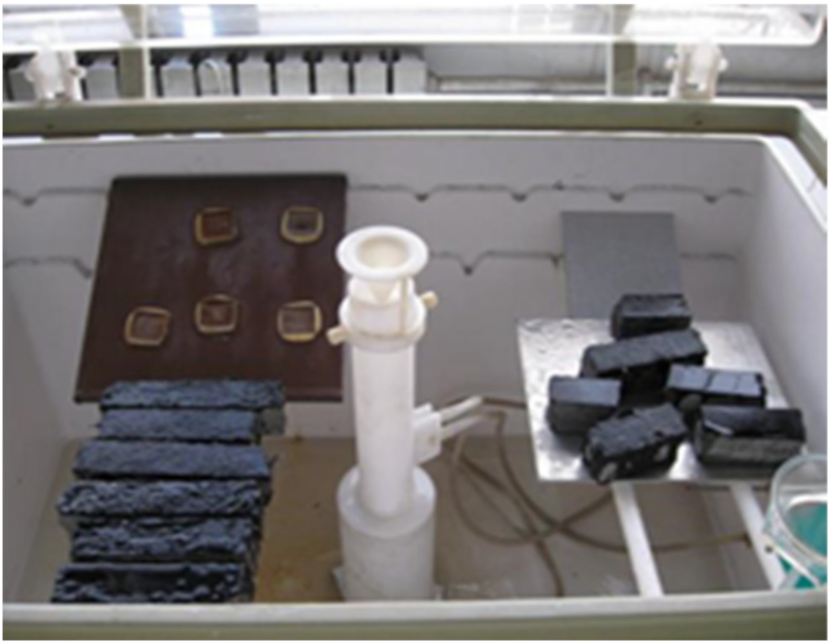
(1) Impermeability of waterproof bonding layer
There was no water seepage in the four waterproof bonding layer structures after water injection for 24 and 48 h. This indicated that the four kinds of waterproof bonding systems had good permeability resistances.
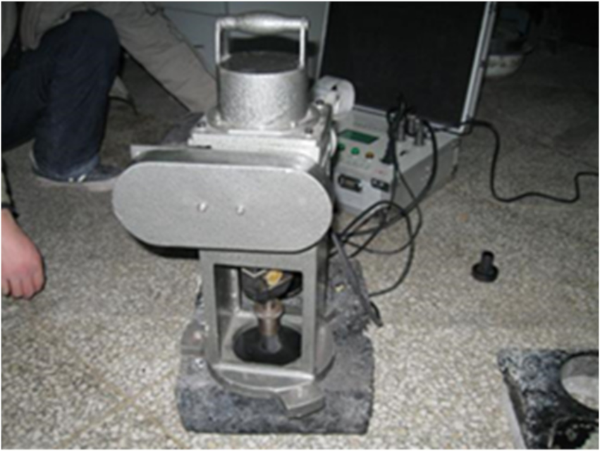
(2) Scalding resistance of waterproof bonding layer
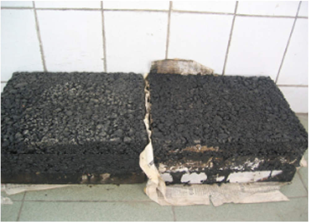
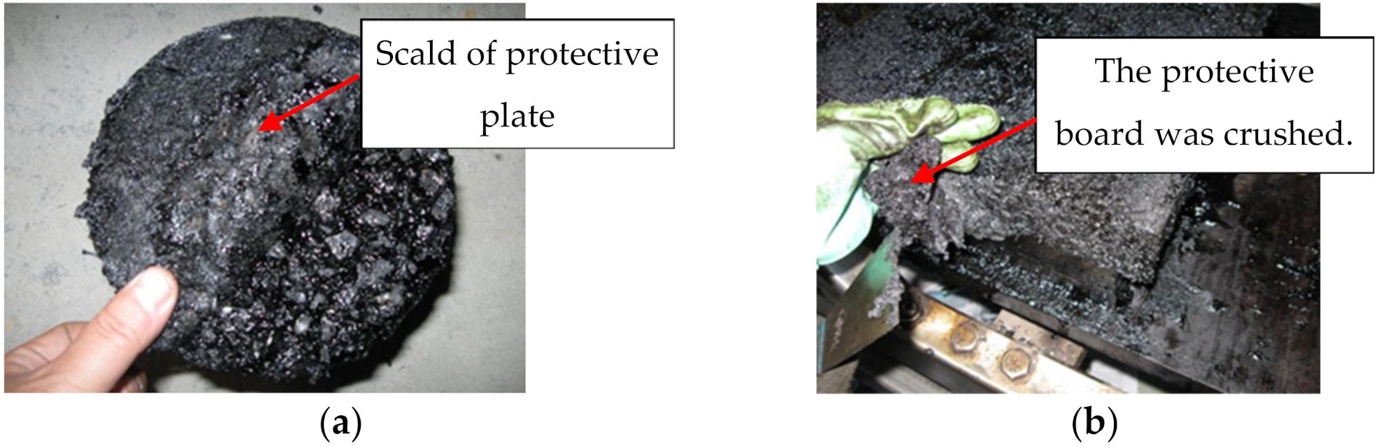
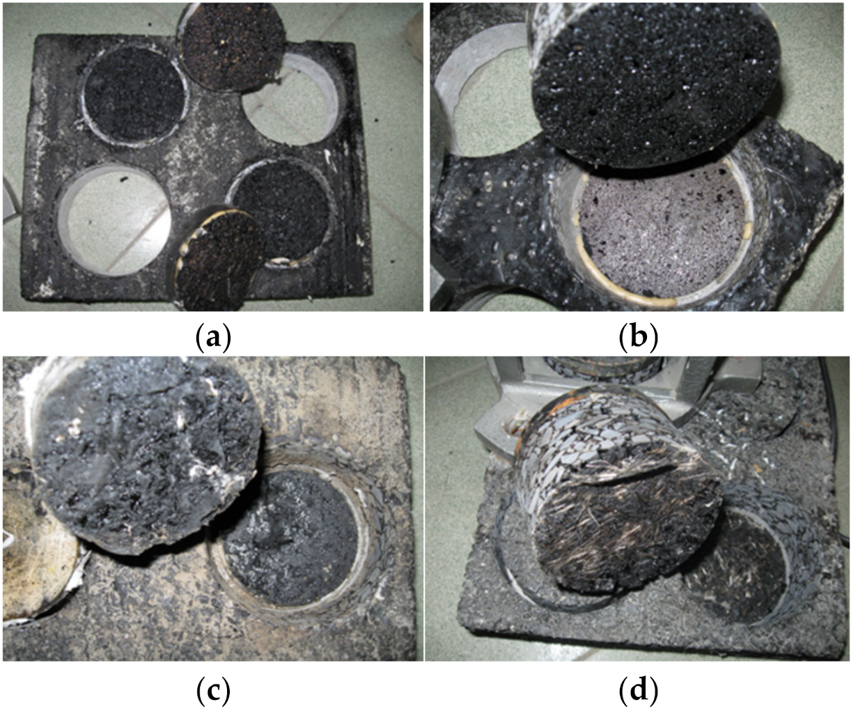
The surface of the waterproof bonding layer had various degrees of damage after rolling. However, the damage of scheme II was the greatest. In the process of rolling, the board that played a protective role was more complicated. When the lower rubber asphalt was less and the concrete slab was relatively flat, the underside of the protective board became scalded as shown in Figure 9a, and there was a layer of non-sticky fiber plant between the rubber asphalt and the concrete, as shown in Figure 9b. In most cases, the protective plate was crushed, resulting in local enrichment. The protective plate was much less viscous than rubber asphalt, which could affect the bonding strength between the layers.
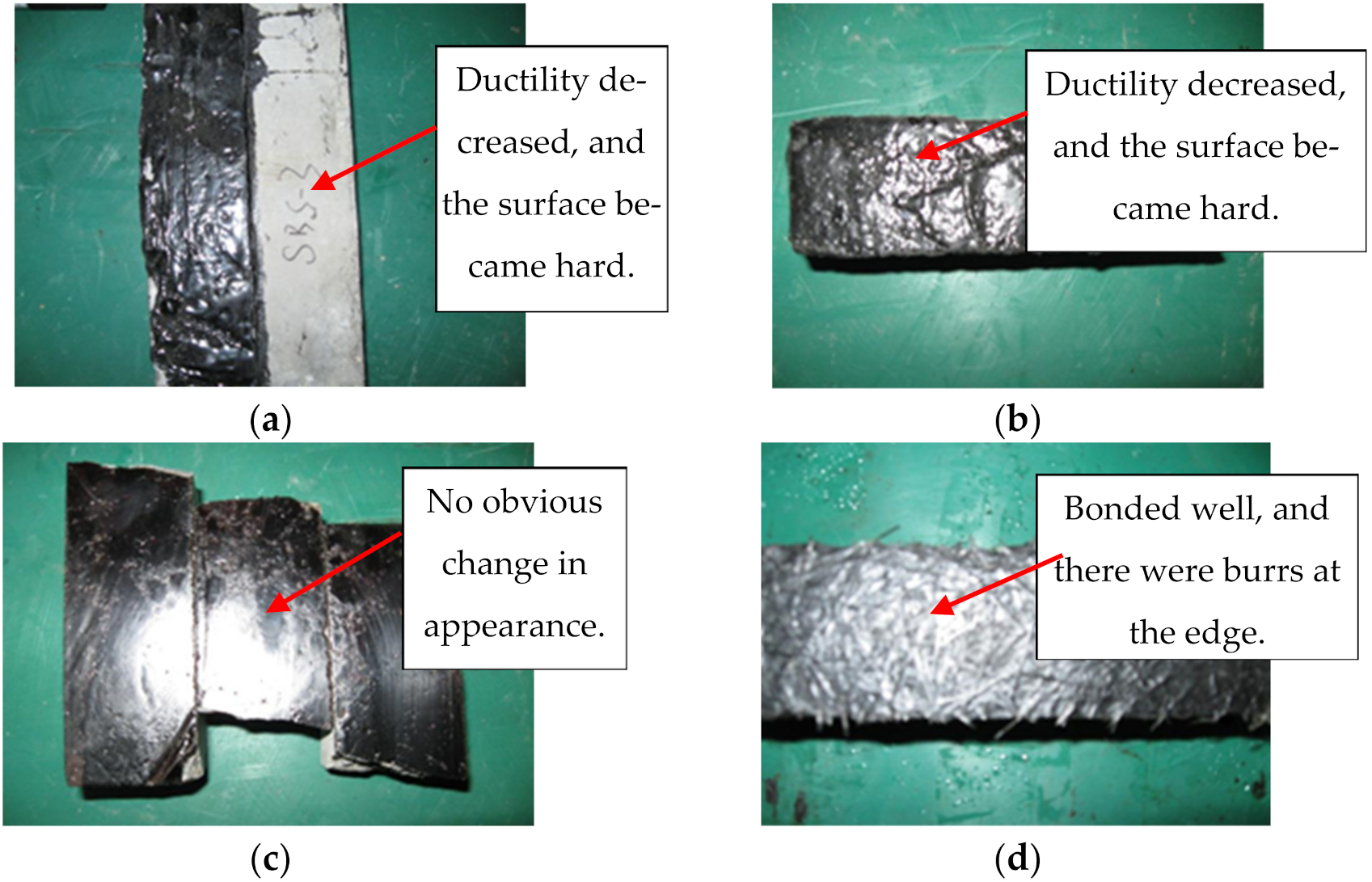
(3) Corrosion resistance of waterproof bonding layer
The test results of the corrosion resistance test are shown in Figure 10.
As shown in Figure 10, after repeated freezing and thawing cycles and salt spray corrosion, the four waterproof layers or undercoats were all well connected to the cement concrete bridge deck. However, the surfaces of schemes I and II became hard when pressed with a finger. The reason may have been that the chemical properties and physical composition of SBS–modified asphalt and rubber asphalt changed after the high-temperature and low-temperature cycles, and the viscosity and toughness decreased. There was no significant change of scheme III, indicating that the GIS–I–type primer had strong durability and corrosion resistance. Scheme IV bonded well, and there were burrs at the edge. Therefore, the long-term coupling effects of water, temperature, and salinity would accelerate the deterioration of waterproof layer materials in a short time. Thus, the influence of these factors should be considered in the design of bridge deck pavement structures.

3.2. Interlayer Bonding Characteristics

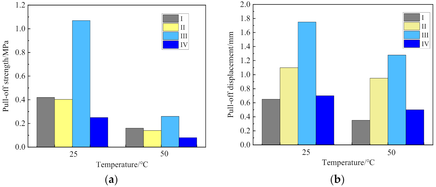
The pull-off test results of the four schemes are shown in Figure 11, and the section forms after the pull-out test are shown in Figure 12.
(1) Pull-off strength and deformation
The pull-off strength and deformation of bridge deck pavement scheme III were the largest at 25 and 50 °C. The pull-off strengths of scheme III at 25 °C were about 2.5-, 2.5-, and 4-times those of schemes I, II, and IV, respectively, and the pull-off strengths at 50 °C were about 1.6-, 2-, and 1.6-times those of schemes I, II, and IV, respectively. Hence, the order of the pull-off strengths of the bonding materials in the different schemes was as follows: III > I > II > IV, indicating that the order of the bonding performances between different waterproof bonding composite systems and cement concrete slab was as follows: III > I > II > IV.
The pull-off strengths of schemes I and II were relatively close, and the pull-off strength at 25 °C was greater than that at 0.35 MPa, which could meet the technical requirements of bridge deck pavement in “Technical Specifications for Construction of Highway Asphalt Pavement” (JTG F40–2004). The bonding principles of the two pavement structures were the same. The modified asphalt waterproof membrane achieved a good connection with the cement concrete bridge deck, and the bonding with the upper SMA–13 pavement layer was enhanced by the modified emulsified asphalt layer. However, the high-temperature pull-off test results showed the bonding strength of scheme II decreased rapidly, indicating that the thickness and temperature stability of the asphalt film determined the stability of the bonding layer. Therefore, it is necessary to optimize the distribution of modified asphalt and the appropriate thickness of rubber asphalt during the design of the bridge deck pavement structure.
The pull-off strength of scheme IV was not ideal. The reason may have been that the manual distribution method was used in the indoor tests, which could not accurately simulate the roller brush construction process. This affected the distribution uniformity of alkali-free glass fibers, resulting in partial thickening and strong plate properties and affecting the connection with the upper layer. Otherwise, based on the damage condition after the pull-off tests, the waterproof coating was well connected with the bridge deck. It cracked at the connection with the upper paving layer or between the waterproof layer. This indicated that scheme IV overemphasized the connection with the bridge deck and the overall anti-cracking capacity, while the current distribution amount and number of glass fibers made the waterproof coating too hard, and the contact area with the mixture of the upper paving layer was small. This reduced the pull-off strength between layers.
The pull-off deformation amounts and pull-off strengths of the four schemes at 50 °C were less than those at 25 °C. The variation range of scheme IV was small, which was mainly due to the low-temperature sensitivity of the cold-constructed GIS–I–type primer, and the temperature had little effect on its resistance to pull-off deformation.
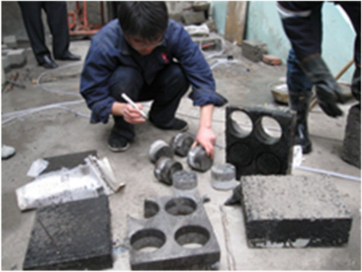
(2) Failure section after pull-off test
The pull-off failure section of scheme III appeared between the pull-off head and the epoxy layer, as shown in Figure 12c. The reason was that, on the one hand, the GIS–I organic solvent was used as the bonding layer material, which had a strong permeability and improved the surface characteristics of the cement concrete bridge deck. On the other hand, the pouring asphalt concrete had a small porosity, good durability, strong adhesion, and good adaptability with deformation. Thus, it increased the interlayer bonding strength.

3.3. Bridge Deck Pavement Structural Properties

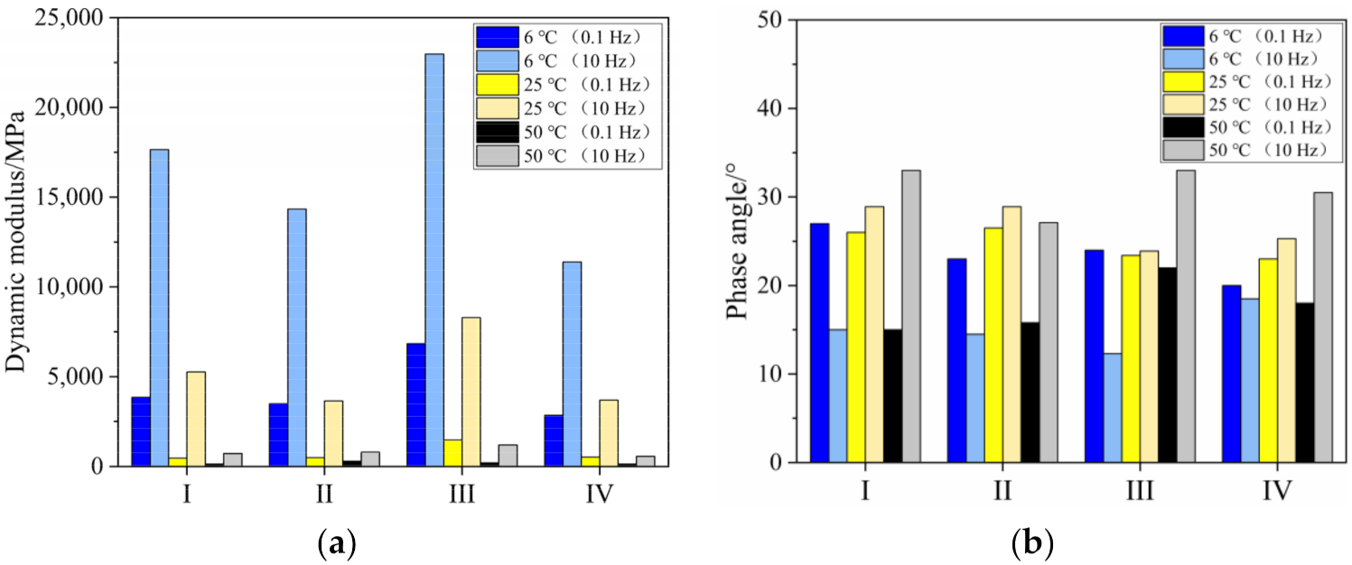
(1) Dynamic mechanical properties
The dynamic modulus test results are shown in Figure 13.
For the same bridge deck pavement structure, the higher the test temperature was, the smaller the measured value of dynamic modulus was. The higher the test frequency was, the larger the measured value of dynamic modulus was. Hence, the order of the dynamic modulus of the different schemes was as follows: III > I > II > IV. The dynamic modulus of scheme III was higher than those of the other three schemes. The dynamic modulus of scheme III at 6, 25, and 50 °C were, respectively, 1.5–2.4 times, 1.5–3.0 times, and 1–2.2 times those of schemes I, II, and IV. This indicated that scheme III exhibited good dynamic mechanical properties.
With the loading frequencies of 0.1 and 10 Hz, the phase angles of the four bridge deck pavement systems changed between 15–30°, indicating that the viscoelastic properties of the four composite structures were stable in the service temperature range of 6–50 °C, which was very beneficial to the stress of the whole bridge deck pavement structure.
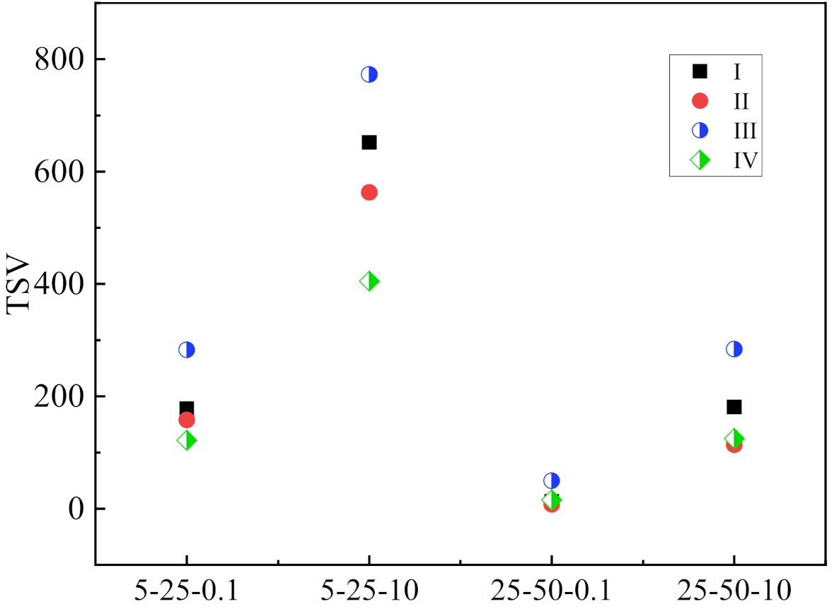
To analyze the influence of the temperature on the dynamic modulus of different bridge deck pavement structures, the temperature-sensitive values (TSVs) of each bridge deck pavement structure with different temperature ranges were calculated. The formula is as follows:
TSV i j = D i D j i j ,
where D i and D j are the dynamic modulus of the pavement structure at test temperatures i and j (°C). The calculation results are shown in Figure 14.
The TSVs of scheme III in the low- and high-temperature ranges were greater than those of the other three schemes, indicating that scheme III’s dynamic mechanical properties were greatly affected by the temperature. Although scheme III had good comprehensive properties in the medium-temperature region, it was still possible to be brittle at low temperatures and creep at high temperatures. This may have been caused by the high asphalt content of GA–10. The TSVs of schemes I and IV were less than those of the other three schemes, indicating that schemes I and IV had good temperature stability.
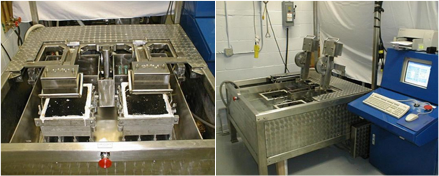
(2) Water-temperature stability
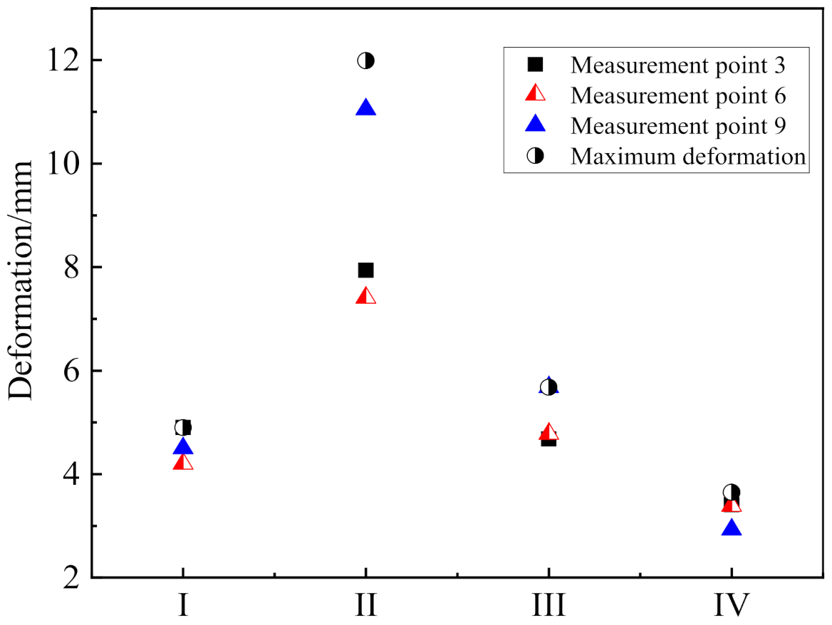
Until the Hamburg wheel tracking test stopped after 20,000 loading cycles, inflection points of the four bridge deck pavement systems did not appear, so the peeling inflection points were not obtained. The Hamburg wheel tracking test system automatically recorded the deformation of 12 points of the left and right wheel ruts, and the maximum deformation generally occurred near point 6. Therefore, the rutting depth and maximum rutting depth of each structure at points 3, 6, and 9 were collected, and the data are shown in Figure 15.
Figure 15 shows that the maximum deformation and the deformation at measurement point 9 of scheme II were larger than 10 mm, while the deformation values of the other three schemes did not exceed 8 mm, indicating that the water-temperature stability of scheme II was poor. Thus, it was not suitable for high-temperature environments.
The order of the deformation amounts of the different schemes were as follows: II > III > I > IV, indicating that the order of the water stabilities of the different waterproof bonding composite systems were as follows: IV > I > III > II. The deformation of scheme I was between 4–5 mm, that of scheme III was between 4.5–6 mm, and that of scheme IV was the smallest, between 2.5–3.5 mm. These results indicated that the water temperature stabilities of schemes I, III, and IV were good. Scheme IV showed an excellent water temperature stability. The reason may be that the fibers played a reinforcement role, effectively improving the overall strength of the waterproof bonding layer and the puncture resistance during construction. Furthermore, it could adapt to the dynamic load and the compression and tensile characteristics of the bridge, and it exhibited good waterproof performances and corrosion resistance.
(3) Static mechanical properties
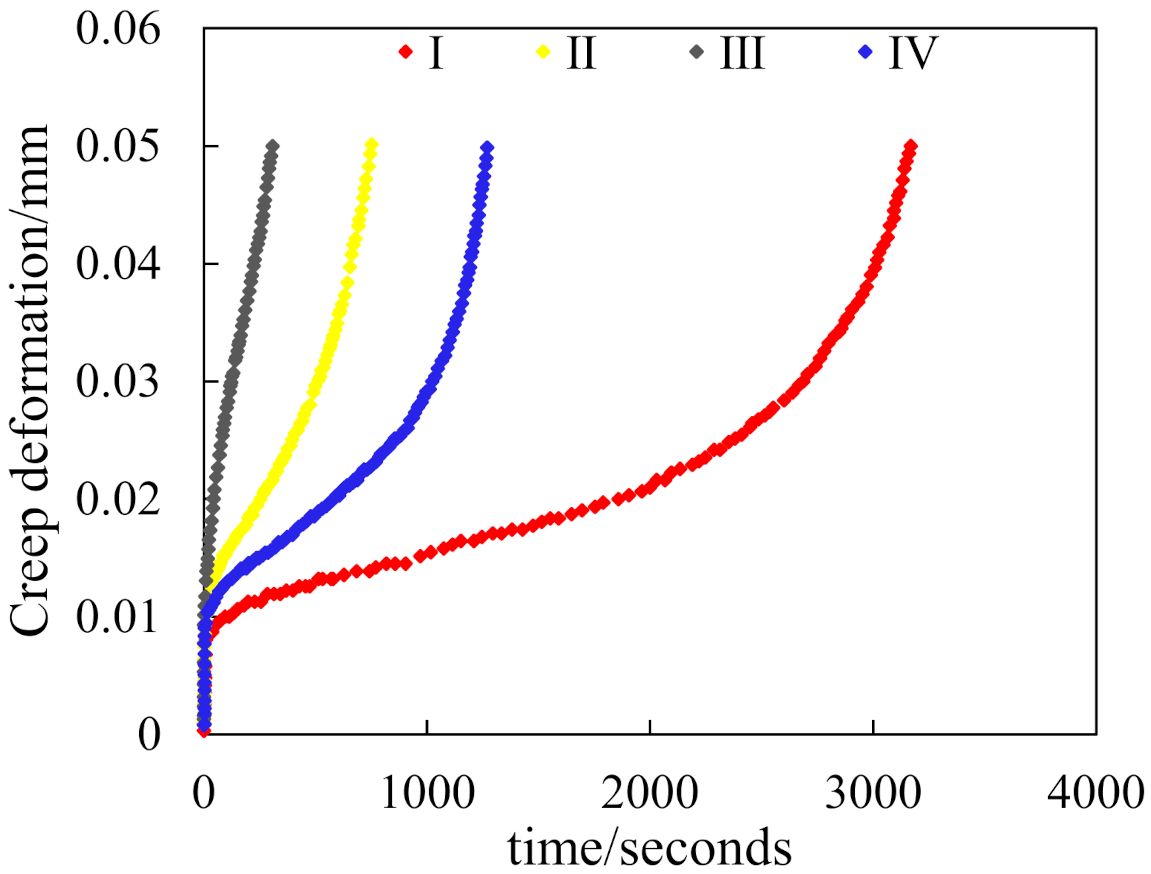
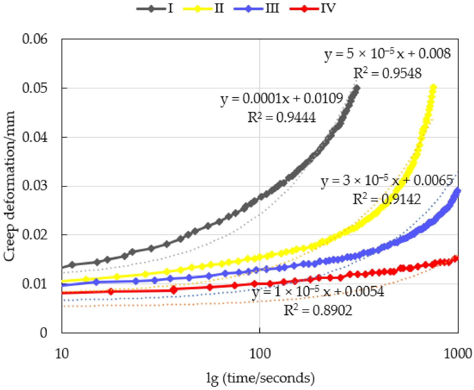
Figure 16 shows the creep deformation and time curves of the four schemes measured by static load creep test. Although the creep deformation increases of different schemes were different at 50 °C, the variations were consistent. If the relationship between the creep deformation and time before rheology was plotted on semi-logarithmic coordinates, there was a good linear relationship between them, the linear correlation formulas were shown in Figure 17. Thus, according to the linear correlation formulas the creep deformation of the four structures can be predicted easily.
The creep deformation amounts of the four schemes under load went through three stages. First, in the migration period, the deformation increased quickly with time. Second, in the stable period, the deformation increased steadily. Third, the deformation increased rapidly with time until failure. The rheological time was defined as the time when the total volume did not change, that is, the beginning of the third stage was the rheological point, and the corresponding time was the rheological time (Ft). Thus, the Ft values of the four schemes were calculated, as shown in Table 7.
The rheological time of scheme IV was the longest, and it was 4.5-, 5.5-, and 1.8-times those of schemes I, II, and III, respectively. The rheological time of scheme III was about 2.5- and 3.0-times greater than that of schemes I and II, respectively, indicating that the schemes III and IV had strong high-temperature deformation resistances. Scheme II had the weakest high-temperature deformation resistance. This result was consistent with the test conclusion of the Hamburg rutting test. Therefore, when the ambient temperature was high, scheme III is recommended.

4. Conclusions

In this study, a series of tests were carried out to evaluate the waterproof bonding material composite systems of cement concrete bridge deck pavement. The following conclusions can be drawn from the tests:
(1)
The four waterproof bonding systems exhibited good permeability resistances. In the process of rolling, scheme II was easily damaged because the protective board was scalded and crushed. According to the corrosion resistance test, the stability of scheme III was the best.
(2)
The pull-off strengths of scheme III at 25 °C were about 2.5-, 2.5-, and 4-times those of schemes I, II, and IV, respectively, and the pull-off strengths at 50 °C were about 1.6-, 2-, and 1.6-times those of schemes I, II, and IV, respectively. The pull-off tests indicated that the bonding performances of different waterproof bonding composite systems and cement concrete slabs ranked as follows: III > I > II > IV, and only scheme IV could not meet the requirements of the standard.
(3)
The dynamic modulus of scheme III was higher than those of the other three schemes. The dynamic modulus of scheme III at 6, 25, and 50 °C were respectively 1.5–2.4 times, 1.5–3.0-times, and 1–2.2-times those of schemes I, II, and IV. This indicated that scheme III exhibited good dynamic mechanical properties. The results of dynamic modulus tests showed that the dynamic modulus of the different schemes ranked as follows: III > I > II > IV. However, the TSV of scheme III in the low-temperature and high-temperature range was greater than those of the other three schemes, indicating that the scheme III dynamic mechanical properties were greatly affected by temperature.
(4)
The results of the Hamburg wheel tracking test were consistent with the static load creep test results. The high-temperature stability of scheme IV was the best, while the stability of schemes III and I were better than that of scheme II. In conclusion, the scheme of concrete bridge deck pavement can be selected according to the environmental conditions and traffic loads, and schemes III and I are recommended.
(5)
In this paper, the performances of four waterproof bonding layer systems for cement concrete bridge deck pavement are tested and evaluated. However, there are many different systems in practical engineering. Therefore, it is necessary to carry out more extensive research on the concrete bridge deck pavement structure, evaluate the properties of more structures, to serve the concrete bridge deck pavement structure design.

Author Contributions

Methodology, J.F. and A.S.; data curation, J.F.; writing—original draft preparation, J.F. and Z.Y.; writing—review and editing, A.S. and Z.Y.; funding acquisition, J.F. All authors have read and agreed to the published version of the manuscript.

Funding

This research was funded by Science and Technology Projects of Inner Mongolia Department of Transportation, (Contract number: NJ-2013-30).

Institutional Review Board Statement

Not applicable.

Informed Consent Statement

Not applicable.

Data Availability Statement

The data that support the findings of this study are available from the corresponding author upon reasonable request.

Conflicts of Interest

The authors declare no conflict of interest. The funders had no role in the design of the study; in the collection, analyses, or interpretation of data; in the writing of the manuscript, or in the decision to publish the results.

References

  1. Manning, D.G. Waterproofing Membranes for Concrete Bridge Decks; Transportation Research Board: Washington, DC, USA, 1995; pp. 55–56. [Google Scholar]
  2. Van Til, C.J.; Carr, B.J.; Vallerga, B.A. Waterproof membranes for protection of concrete bridge decks-laboratory phase. NCHRP 1976, 165, 66–67. [Google Scholar]
  3. Zhou, Q.; Xu, Q. Experimental study of waterproof membranes on concrete deck: Interface adhesion under influences of critical factors. Mater. Des. 2009, 30, 1161–1168. [Google Scholar] [CrossRef]
  4. PRIC, A.R. Waterproofing of Concrete Bridge Decks Site Practice and Failures. TRRL 1991, 317, 57–60. [Google Scholar]
  5. PRICE, A.R. Laboratory Tests on Waterproofing Systems for Concrete Bridge Decks. TRRL 1990, 248, 35–39. [Google Scholar]
  6. Chen, X.; Zhu, Y.; Cai, D.; Xu, G.; Dong, T. Investigation on Interface Damage between Cement Concrete Base Plate and Asphalt Concrete Waterproofing Layer under Temperature Load in Ballastless Track. Appl. Sci. 2020, 10, 2654. [Google Scholar] [CrossRef] [Green Version]
  7. Qian, G.; Li, S.; Yu, H.; Gong, X. Interlaminar Bonding Properties on Cement Concrete Deck and Phosphorous Slag Asphalt Pavement. Materials 2019, 12, 1427. [Google Scholar] [CrossRef] [Green Version]
  8. Haynes, M.A.; Coleri, E.; Obaid, I. Performance of Waterproofing Membranes to Protect Concrete Bridge Decks. Transp. Res. Rec. 2021, 2675, 1693–1706. [Google Scholar] [CrossRef]
  9. Qiu, Y.J.; Shaoke, A.; Ali, R.; Ai, C.F. Evaluation and optimization of bridge deck waterproof bonding system using multi-objective grey target decision method. Road Mater. Pavement Des. 2020, 21, 1844–1858. [Google Scholar] [CrossRef]
  10. Zhang, K.; Luo, Y.F. Interlaminar Performance of Waterproof and Cohesive Materials for Concrete Bridge Deck under Specific Test Conditions. J. Mater. Civ. Eng. 2018, 30, 04018161. [Google Scholar] [CrossRef]
  11. Ye, F.; Zhou, K.; Jia, X. Evaluation of shear performance of flexible waterproof-adhesive layer in concrete bridge pavement based on grey correlation analysis. Road Mater. Pavement Des. 2009, 10, 349–360. [Google Scholar]
  12. Xie, H.; Zhao, R.; Wang, R.; Xi, Z.; Yuan, Z.; Zhang, J.; Wang, Q. Influence of thermal shock on the performance of B-staged epoxy bond coat for orthotropic steel bridge pavements. Constr. Build. Mater. 2021, 294, 123598. [Google Scholar] [CrossRef]
  13. Wang, H.; Jin, C.; Liu, H.; Xue, Z. Rubber asphalt waterproof adhesive layer for steel bridge gussasphalt pavement. Int. J. Struct. Integr. 2020, 12, 261–270. [Google Scholar] [CrossRef]
  14. Li, Y.; Li, S.; Lv, R.; Zhang, P.; Xu, Y.; Hou, G.; Cui, C. Research on failure mode and mechanism of different types of waterproof adhesive materials for bridge deck. Int. J. Pavement Eng. 2015, 16, 602–608. [Google Scholar] [CrossRef]
  15. Feng, D.C.; Xu, M.; Wei, W.D. Analysis of the Influence of Cement Concrete Deck Moisture Content on the Bonding Performance of Waterproof Adhesion Layer. J. Highw. Transp. Res. Dev. 2014, 8, 31–36. [Google Scholar] [CrossRef]
  16. Mazzotta, F.; Lantieri, C.; Vignali, V.; Simone, A.; Dondi, G.; Sangiorgi, C. Performance evaluation of recycled rubber waterproofing bituminous membranes for concrete bridge decks and other surfaces. Constr. Build. Mater. 2017, 136, 524–532. [Google Scholar] [CrossRef]
  17. Xu, G.; Zhou, J.; Chen, X.; Liang, Y.; Cai, D.; Lou, L. Temperature features of the asphalt concrete waterproofing layer on high-speed railway in cold regions. Constr. Build. Mater. 2021, 305, 124665. [Google Scholar] [CrossRef]
  18. Shi, X.; Zhang, H.; Bu, X.; Zhang, G.; Zhang, H.; Kang, H. Performance evaluation of BDM/unsaturated polyester resin-modified asphalt mixture for application in bridge deck pavement. Road Mater. Pavement Des. 2020, 23, 684–700. [Google Scholar] [CrossRef]
  19. Zhang, M.; Hao, P.; Men, G.; Liu, N.; Yuan, G. Research on the compatibility of waterproof layer materials and asphalt mixture for steel bridge deck. Constr. Build. Mater. 2021, 269, 121346. [Google Scholar] [CrossRef]
  20. Xu, Y.; Lv, X.; Ma, C.; Liang, F.; Qi, J.; Chou, Z.; Xu, S. Shear Fatigue Performance of Epoxy Resin Waterproof Adhesive Layer on Steel Bridge Deck Pavement. Front. Mater. 2021, 7, 469. [Google Scholar] [CrossRef]
  21. Cao, M.-M.; Huang, W.-Q.; Lu, Y.; Tan, Q.-Q. Test and Evaluation Method of lnterlaminar Shear Performance of Composite Pavement. J. Highw. Transp. Res. Dev. 2018, 12, 33–43. [Google Scholar] [CrossRef]
  22. Liu, Y.; Wu, J.T.; Chen, J. Mechanical properties of a waterproofing adhesive layer used on concrete bridges under heavy traffic and temperature loading. Int. J. Adhes. Adhes. 2014, 48, 102–109. [Google Scholar] [CrossRef]
  23. Kruntcheva, M.R.; Collop, A.C.; Thom, N.H. Properties of asphalt concrete layer interfaces. J. Mater. Civ. Eng. 2006, 18, 467–471. [Google Scholar] [CrossRef]
  24. Xu, Q.; Zhou, Q.; Medina, C.; Chang, G.K.; Rozycki, D.K. Experimental and numerical analysis of a waterproofing adhesive layer used on concrete-bridge decks. Int. J. Adhes. Adhes. 2009, 29, 525–534. [Google Scholar] [CrossRef]
  25. Guo, M.; Tan, Y.; Wang, L.; Ye, Z.; Hou, Y.; Wu, J.; Yang, H. Study on water permeability, shear and pull-off performance of waterproof bonding layer for highway bridge. Int. J. Pavement Res. Technol. 2018, 11, 396–400. [Google Scholar] [CrossRef]
  26. Jiao, Y.; Zhang, Y.; Fu, L.; Guo, M.; Zhang, L. Influence of crumb rubber and tafpack super on performances of SBS modified porous asphalt mixtures. Road Mater. Pavement Des. 2019, 20, S196–S216. [Google Scholar] [CrossRef]
  27. Zhang, H.; Gao, P.; Zhang, Z.; Pan, Y. Experimental study of the performance of a stress-absorbing waterproof layer for use in asphalt pavements on bridge decks. Constr. Build. Mater. 2020, 254, 119290. [Google Scholar] [CrossRef]
  28. Guo, L.C.; Zeng, G.D. Study on mechanical properties of typical steel bridge deck pavement waterproof bonding system. J. Phys. Conf. Ser. 2021, 1802, 022018. [Google Scholar] [CrossRef]
  29. Ai, C.F.; Huang, H.W.; Ali, R.; Shaoke, A. Establishment of a new approach to optimized selection of steel bridge deck waterproof bonding materials composite system. Constr. Build. Mater. 2020, 264, 120269. [Google Scholar] [CrossRef]
  30. AASHTO. LRFD Bridge Design Specifications, 3rd ed.; American Association of State Highway and Transportation of Officials: Washington, DC, USA, 2004. [Google Scholar]
  31. AASHTO. AASHTO Guide Specifications for Fatigue Evaluation of Existing Steel Bridges; American Association of State Highway and Transportation of Officials: Washington, DC, USA, 1990. [Google Scholar]
  32. BS5400 Steel, Concrete and Composite Bridges; British Standard Institute: London, UK, 2000.
  33. AASHTO. AASHTO Guide Manual for Condition Evaluation and Load and Resistance Factor Rating (LRFR) of Highway Bridges; American Association of State Highway and Transportation of Officials: Washington, DC, USA, 2002. [Google Scholar]
  34. Wang, T.L.; Liu, C.; Huang, D.; Shahawy, M. Truck loading and fatigue damage analysis for girder bridges based on weightin-motion data. J. Bridge Eng. 2005, 10, 12–20. [Google Scholar] [CrossRef]
  35. Zhao, P.; Dong, M.; Yang, Y.; Shi, J.; Wang, J.; Wu, W.; Zhao, X.; Zhou, X.; Wang, C. Research on the Mechanism of Surfactant Warm Mix Asphalt Additive-Based on Molecular Dynamics Simulation. Coatings 2021, 11, 1303. [Google Scholar] [CrossRef]
  36. Ma, J.; Hu, M.; Sun, D.; Lu, T.; Sun, G.; Ling, S.; Xu, L. Understanding the role of waste cooking oil residue during the preparation of rubber asphalt. Resour. Conserv. Recycl. 2020, 167, 105235. [Google Scholar] [CrossRef]
  37. Xiao, X.; Wang, J.; Cai, D.; Lou, L.; Xiao, F. A novel application of thermoplastic polyurethane/waste rubber powder blend for waterproof seal layer in high-speed railway. Transp. Geotech. 2021, 27, 100503. [Google Scholar] [CrossRef]
  38. Wang, F.; Lei, S.; Ou, J.; Li, W. Effect of PDMS on the waterproofing performance and corrosion resistance of cement mortar. Appl. Surf. Sci. 2020, 507, 145016. [Google Scholar] [CrossRef]
Figure 1. The research flowchart.
Coatings 12 00308 g001
Figure 2. Cement concrete deck.
Coatings 12 00308 g002
Figure 3. Formed bridge deck pavement specimens.
Coatings 12 00308 g003
Figure 4. Drilling cylindrical specimen.
Coatings 12 00308 g004
Figure 5. ZHY permeability instrument.
Coatings 12 00308 g005
Figure 6. Device for simulating chloride penetration.
Coatings 12 00308 g006
Figure 7. Pull-off test instrument.
Coatings 12 00308 g007
Figure 8. Hamburg test instrument.
Coatings 12 00308 g008
Figure 9. Burst resistance test phenomena of scheme II. (a) Scald of protective plate. (b) Protective board was crushed.
Coatings 12 00308 g009
Figure 10. Specimen after corrosion resistance test. (a) Results of scheme I. (b) Results of scheme II. (c) Results of scheme III. (d) Results of scheme IV.
Coatings 12 00308 g010
Figure 11. Test results of pull-off test. (a) Pull-off strength. (b) Pull-off displacement.
Coatings 12 00308 g011
Figure 12. Sections of specimens after pull-off test. (a) Scheme I. (b) Scheme II. (c) Scheme III. (d) Scheme IV.
Coatings 12 00308 g012
Figure 13. Test results of dynamic modulus. (a) Dynamic modulus. (b) Phase angle.
Coatings 12 00308 g013
Figure 14. Temperature sensitive value.
Coatings 12 00308 g014
Figure 15. Hamburg wheel tracking deformation.
Coatings 12 00308 g015
Figure 16. Results of static load creep test.
Coatings 12 00308 g016
Figure 17. Deformation–time semilog curves.
Coatings 12 00308 g017
Table 1. Cement concrete bridge deck systems.
SchemeWaterproof Bonding LayerUpper Bridge Deck Pavement Structure
IGravel asphalt sealing layer + 20 mm AC–5 + modified emulsified asphalt60 mm SMA–13
II5 mm rubber asphalt + 3.6 mm protective board + modified emulsified asphalt 70 mm SMA–13
IIIGIS–I primer + 30 mm GA–1050 mm SMA–13
IV1.2 mm fiber-reinforced waterproof coating (five–layer spraying)80 mm SMA–13
Table 2. Aggregate gradation of the three mixtures.
Sieve Size (mm)16.013.29.504.752.361.180.600.300.150.075Binder Content/%
AC–5100100100956545302012.57.56.1
GA–101001009071.555.5453933.530257.3
SMA–1310081.661.224.219.916.814.512.410.99.86.2
Table 3. Technical indices of rubber asphalt.
ProjectMeasured ValueTest Method
Penetration at 25 °C,100 g, and 5 s (0.1 mm)47.5T0604
Fluidity at 60 °C (Pa·s)2.3ASTM D5329
Softening point (°C)89.5T0606
G*/sinδ (with the pressure of 4800 Pa and rotation speed of 8 rad/s)18.7T0628
G*/sinδ (with the pressure of 1600 Pa and rotation speed of 10 rad/s)4.95T0628
Table 4. Hard surface time and curing time of GIS–I adhesives at different temperatures.
Temperature (°C)Hard Surface Time (h)Curing Time (h)
5848
15536
25324
35218
451 12
Table 5. Technical indices of polymer-modified asphalt waterproof coating.
NumberProjectType II
1Solid content≥50
2Hard surface time, h<2
3Actual dry time, h4
4Heat resistance, °C180
5Impermeable, 0.3 MPa, 30 minImpermeable
6Low-temperature flexibility, °C−20
7Tensile strength, MPa1.0
8Elongation at break, %≥800
9Salt treatmentTensile strength retention rate, %≥80
Elongation at break, %≥800
Low-temperature flexibility, °C−15
Quality increase, %≤2.0
10Hot agingTensile strength retention rate, %≥80
Elongation at break, %≥600
Low-temperature flexibility, °C−15
Heating expansion rate, %≤1.0
Quality loss, %≤1.0
Table 6. Technical indicators of alkali-free glass fiber.
Burn LossWater ContentStiffnessDispersion
0.80.1≥140≥95
Table 7. Rheological time of four schemes.
SchemeIIIIIIIV
Rheological time/seconds3642989051636
Publisher’s Note: MDPI stays neutral with regard to jurisdictional claims in published maps and institutional affiliations.

