Article

Effect of Cr3C2 Content on the Microstructure and Wear Resistance of Fe3Al/Cr3C2 Composites

1
Department of Mechanical Engineering, Tsinghua University, Beijing 100084, China
2
Beijing Technology Research Branch of Tian Di Science & Technology Co., Ltd., Chinese Institute of Coal Science, Beijing 100013, China
3
Welding Institute, Central Iron and Steel Research Institute, Beijing 100081, China
4
Department of Industrial and Materials Science, Chalmers University of Technology, SE-41296 Gothenburg, Sweden
*
Authors to whom correspondence should be addressed.
Coatings 2022, 12(12), 1980; https://doi.org/10.3390/coatings12121980
Submission received: 3 November 2022 / Revised: 8 December 2022 / Accepted: 12 December 2022 / Published: 17 December 2022
(This article belongs to the Special Issue Laser Cladding Coatings: Microstructure, Properties, and Applications)

Abstract

:
In this paper, an engine piston ring coating comprising composite material of Fe3Al and Cr3C2 mixed powder was prepared by laser cladding onto carbon structural steel. The microstructure and tribological properties of the cladding materials were investigated through X-ray diffraction (XRD), scanning electron microscopy (SEM), energy dispersive spectroscopy (EDS), transmission electron microscopy (TEM), and wear tests. The influence mechanism of the Cr3C2 content in cladding powder was studied. During the process of wear, the soft Fe3Al/Fe2AlCr matrix is first ground off, and the hard Cr7C3 phase initially supports the abrasive surface before being worn away into hard particles, resulting in abrasive wear. With the increase in Cr3C2 content, the hardness of the cladding layer increases, the proportion of the Cr7C3 phase increases, and the morphology changes from a sparse network to a dense floccule. Of the cladding layers with different Cr3C2 content, the 15 wt.% Cr3C2 cladding layer had the lowest friction coefficient, and the 25 wt.% Cr3C2 cladding layer had the lowest wear rate. The low wear rate of the 25 wt.% Cr3C2 cladding layer can be attributed to the fact that adhesive wear does not easily occur and the fine microstructure of the strengthening phase, which facilitates better separation in the grinding surfaces.

Graphical Abstract

1. Introduction

With the development of high-temperature, wear-resistant structural materials, the research into intermetallic compounds and their composites has been gradually increasing. TheFe3Al alloy and its composite materials have good resistance against wear, high temperatures, and oxidation [1,2,3,4]. Compared with other intermetallic compounds, Fe and Al are relatively cheap, representing a large raw material cost advantage. Thus, alloys comprising Fe and Al have great application potential in ships, automobiles, aviation, and other fields.
Due to the importance of developing a new generation of wear-resistant piston ring materials, Chen et al. [5] utilized a TiC-reinforced Fe3Al base composite material for coating via laser cladding onto the stainless steel base material. This type of coating has good wear resistance, and its performance is gradually enhanced due to the increase in the strengthening phase. As the load is increased, the wear type changes from abrasive to adhesive. Zhang et al. [6] prepared a nano-Fe3Al/Al2O3 gradient coating using the laser-cladding method. Their experimental results showed that the nanocoating had significantly improved wear resistance, hardness, and corrosion resistance, and the microstructure and properties of the gradient material changed significantly at different locations.
Cr3C2 has a high thermal hardness, good corrosion resistance, and high oxidation resistance, which are compatible with the thermal expansion coefficient of most alloys. Therefore, the addition of Cr3C2 to the matrix as a hard strengthening phase will greatly improve the wear resistance of a material. Zhao et al. [7] obtained a high-temperature, wear-resistant material coating with excellent comprehensive performance by preparing an Ni3Al base material composite reinforced with Cr3C2 particles. They found that the laser-clad Ni3Al alloy and Ni3Al/Cr3C2 composite coatings differed in terms of their microstructures, mechanical properties, and friction and wear properties. Chen et al. [8] prepared wear-resistant cladding materials by laser cladding onto a 304 stainless steel base material, using either pure Ni3Al or Ni3Al/Cr3C2 mixed powder. By analyzing its structure, the cladding layer that was prepared from mixing powder was found to be mainly composed of an Ni3Al matrix phase and in situ, self-generated M7C3. The wear resistance of the cladding layer was also characterized.
Laser cladding refers to the use of a laser as a heat source to deposit the required material onto a substrate. The dilution rate of laser cladding is very low due to the higher concentration of energy. Due to the rapid heating and cooling in this process, the heat-affected zone of the material is small. In particular, when used to melt different materials, the characteristics of laser cladding are vastly superior to other heating methods [9]. After cladding, the material has good grain structure and properties similar or even superior to the intrinsic material.
The research on the Fe3Al alloy and Fe3Al matrix composite materials has mainly focused on Fe-Al/Al2O3, Fe-Al/WC, and other composite materials, and in the research on Fe-Al/Cr3C2 composite materials, only thermal spraying coating technology has been largely considered. Systematic investigations on the wear resistance of the Fe3Al/Cr3C2 cladding layer, the influence of Cr3C2 on the properties of the Fe3Al/Cr3C2 composite, and the friction and wear mechanism of the Fe3Al/Cr3C2 composite laser cladding are still lacking. Compared with previous studies, the main novelty of this work is that we studied the effect of Cr3C2 content on the microstructure and wear resistance of Fe3Al/Cr3C2 composites. The influence mechanism of carbide behavior on the wear resistance of Fe3Al/Cr3C2 composites was also investigated.

2. Experimental Materials and Method

2.1. Composite Powders

Carbon structural steel was used as the base material. The cladding powder was a mixture of Fe3Al and Cr3C2 powder of particle size 75–125 μm. The Cr3C2 powder was a commercial pure Cr3C2 prepared by crushing a large Cr3C2 block. The chemical composition of Fe3Al powder is shown in Table 1.
Aluminum blocks and nickel powder (CISRI, Beijing, China), applied as raw materials for powder atomization, were melted in a vacuum furnace at 1900~2000 °C for 1 h and then atomized into powder. In this paper, cladding layers with 0, 5, 15, 25, and 35 wt.% Cr3C2 content were prepared and investigated.

2.2. Preparation of the Cladding Layer

A YLS-6000 fiber laser-cladding system composed of a YLS-6000 fiber laser (IPG Photonic, Oxford, MA, USA), KUKA mechanical arm, and powder feeder was utilized for the laser-cladding experiment, and images and details of the setup are shown in Figure 1. The laser wavelength was 1.07 μm. A Gaussian distribution focusing lens was selected for use on the laser head to generate a rectangular laser spot of size 2 mm × 5 mm. The powder feeding type was coaxial powder feeding; the shielding gas and powder-carrying gas were high-purity argon (99.99%), and the flow of shielding gas was 15 L/min. Before cladding, the surface of the base material was polished with 320# SiC sandpaper to reduce its brightness and remove the surface oxide layer, which was followed by cleaning and wiping of the polished base material with acetone.
Through the preliminary experiment, process parameters that led to fewer cracks and better forming were determined, as were the following parameters: laser power of 2.2 kW, laser scanning speed of 0.002 m/s, and powder feed rate of 0.644 kg/h. These process parameters were used to prepare cladding layers with five different levels of Cr3C2 content.

2.3. Microstructure Characterization

Sections of the cladding layer along the direction perpendicular to the cladding layer were obtained by wire-electrode cutting. The sample sizes were 10 mm × 10 mm and the full thickness of the section. We sanded the sections with 320#, 600#, and 1000# sandpaper in succession, and the samples were then polished with a 5 μm diamond-polishing agent. After polishing, the samples were cleaned and dried. Phase analysis of the alloyed powder and cladding layer was carried out using a Bruker D8 ADVANCE X-ray diffractometer (XRD, BRUKER, Karlsruhe, Germany) with a scanning speed of 2°/min. In order to observe the microstructure of the cladding layer, Zeiss high-resolution field emission scanning electron microscopy (SEM, ZEISS, Jena, Germany) was used to observe the cross section of the cladding layer. An Auriga focused ion beam Zeiss FIB was used to prepare TEM samples. The selected observation area was coated and marked using a vapor deposition system (GIS), and the samples were then sheared to an appropriate thickness using an ion beam. The prepared samples were observed by high-resolution transmission electron microscopy (JEM-2010, JEOL, Tokyo, Japan). The hardness distribution from the top of the cladding layer to the substrate material was measured using an FM300 microhardness tester (F-T, Tokyo, Japan).

2.4. Wear Test

A multifunctional friction and wear testing machine (UMT, BRUKER, Madison, MA, USA) was used for the wear test. As shown in Figure 2 below, the friction type was pin disk surface contact cyclic friction. The pins were Ø3 mm in size and made of the Fe3Al/Cr3C2 cladding layer and common wear-resistant vermicular cast iron. The discs were made of gray cast iron and were cut from the inner wall of the engine to a size of Φ 24 mm × 7.88 mm. The friction and wear test conditions were as follows: dry friction and wear, load of 30 N, rotation speed of 200 r/min, rotation radius of 7 mm, testing time of 60 min, and room temperature. In this investigation, two friction indices are mainly considered: the friction coefficient and the wear rate. There are many influencing factors of friction and wear, among which the surface roughness of the contact pin and disc has a great influence on the friction coefficient. Therefore, before the experiment, we adopted finish grinding to adjust the surface roughness to Ra0.4. To more accurately measure the wear rate, the grinding pins and discs were ultrasonically cleaned with acetone for 10 min. Following this, the cleaned grinding pin and disc were weighed, and the measured masses were recorded as M1 and M2, respectively. After the experiment, the grinding pin and disc were again ultrasonically cleaned with acetone for 10 min to remove residual wear debris and determine the mass of the grinding pin and disc, M3 and M4, by weighing. We calculated M1−M3 and M2−M4, which represent the wear loss, for use in the subsequent wear rate calculation. The friction coefficient was obtained in real time during the friction experiment. Thereafter, the pins were scanned using a 3D white light interferometer. The morphology of the worn surface and section were observed by high-resolution field emission scanning electron microscopy (SEM, ZEISS, Jena, Germany).

3. Results

3.1. Microstructure and Phase Composition of the Cladding Layer

A large number of studies [10,11,12] have shown that the size and distribution of the strengthening phase in a wear-resistant coating have a large influence on its performance. In order to find the reasons for different wear rate results, the microstructure morphology was first analyzed. From Figure 2, we can see that the Cr3C2 content has a notable influence on the microstructure of the cladding layer. Figure 2a shows that no apparent strengthening phase can be observed in the 0 wt% Cr3C2 cladding layer. Figure 3b–d show that at 5, 15, and 25 wt.% Cr3C2 content, a strengthening phase appears as a reticular structure in the base material. With the increase in Cr3C2 content, the reticular structure becomes denser, and the area of voids decrease. Figure 3e shows that the strengthening phase structure changes from its original reticular structure to a block-shaped structure in the 35 wt% Cr3C2 cladding layer.
The phase composition of the cladding layer was analyzed. XRD phase analysis of the cladding layers with different Cr3C2 content was carried out, and the results are shown in Figure 3. Figure 3a shows the presence of only one phase of Fe3Al in the 0 wt.% Cr3C2 cladding layer. Figure 3b–e show that the 5, 15, 25, and 35 wt% Cr3C2 cladding layers contain Fe3Al, Fe2AlCr, and Cr7C3. Because the peak characteristic of Fe3Al coincides with that of Fe2AlCr, the existence of an Fe2AlCr phase could not be determined from the XRD results alone. As shown in Table 2 below, the number of cracks in the cladding layer gradually decreases and then increases with increasing Cr3C2 content. This indicates that the addition of Cr3C2 initially improves the plasticity of brittle Fe3Al [13]. Fe2AlCr phases are characterized by good plasticity [14], and thus, the appearance of this layer results in reduced cracking of the cladding layer. With the increase in Cr3C2 content, the brittle phase of Cr7C3 in the cladding layer increases. Although the content of the Fe2AlCr phase also increases, it is still brittle as a whole, so the cracks increase again.
Figure 4 shows TEM images and selected electron diffraction patterns of the 15 and 35 wt.% Cr3C2 cladding layers. Figure 4a,b show the TEM images of the 15 and 35 wt.% Cr3C2 cladding layers, respectively. Figure 4c,d show the electron diffraction pattern of the Fe3Al/Fe2AlCr and Cr7C3 structures, respectively. The strengthening phase exists in the form of Cr7C3. In the 15 wt.% Cr3C2 cladding layer, Cr7C3 has a strip or punctate structure, whereas in the 35 wt.% Cr3C2 cladding layer, it has a polygon structure. In terms of size, the strengthening phase is larger in the 35 wt.% Cr3C2 cladding layer.

3.2. Friction Coefficient and Wear Loss

The friction coefficient curves of each group are shown in Figure 5. Due to the significant amount of time required for the wear test, in the last stage of the test, most of the friction coefficient curves were relatively stable and could be directly obtained through reading. According to the curves, the vermicular cast iron group had a stable friction coefficient of 0.7. In the cladding layer groups, except the layers with 35 wt.% Cr3C2, the values for stable friction coefficients were all below 0.65. The coefficient of the 15 wt.% Cr3C2 group was 0.32, which was the lowest. In terms of the fluctuation of the friction coefficient, except the 5 wt.% Cr3C2 cladding group fluctuating in the end, the friction coefficient curves of the other groups were relatively stable in the last stage. To demonstrate that this phenomenon of friction coefficient instability was not accidental or the result of a single test, we repeated the tests with the 5 wt.% Cr3C2 content group, and the friction coefficient curves were obtained as shown in Figure 6. Table 3 shows the wear loss for all three tests. The differences among the coefficients of each curve were small, and the overall trends of the curves were the same. The error was within the allowable range of the test. We can draw the conclusion that fluctuation is a common phenomenon in specific groups.
Table 4 shows the wear loss in the wear tests. From the results of the pin wear rate, all the groups were below 1 × 10⁻⁵ mm3/N·m, except the 5 wt.% Cr3C2 group. Figure 7 shows that the hardness of the cladding layer increases with the increase in Cr3C2 content. In the inner parts of the cladding layer, the hardness of different positions is similar. When the Cr3C2 content was 15 and 25 wt.%, the wear loss was quite low and was correlated with hardness. The 5 and 35 wt.% groups demonstrated deviance with large wear rates. In terms of disc wear loss, the results of the 0, 5, and 15 wt.% groups were close, with the lowest determined for 25 wt.% Cr3C2 content and the highest for 35 wt.% Cr3C2 content.

3.3. Wear Mechanism of Cladding Layers

A 3D white light interferometer was used to carry out the observation of the worn pins and discs. The results are shown in Figure 8. Figure 8a shows the 3D profiles of the 0 wt.% Cr3C2 cladding layer. Figure 8b,f show the 3D profiles of the 5 wt.% Cr3C2 cladding layer. Figure 8c shows 3D profiles of the 15 wt.% Cr3C2 cladding layer. Figure 8d shows the 3D profiles of the 25 wt.% Cr3C2 cladding layer. Figure 8e shows the 3D profiles of the 35 wt.% Cr3C2 cladding layer. Very obvious furrows can be observed on the surfaces of the pins and discs, which indicate the obvious occurrence of abrasive wear. Moreover, with the increase in Cr3C2 content, the surface-height difference of pins gradually increases, and abrasive wear became increasingly serious. In addition to obvious furrows, deep pits could also be found on the surface of the grinding pin of the 5 wt.% Cr3C2 group, which demonstrates that not only abrasive wear, but also serious adhesive wear occurred [15].
Through SEM observation of the worn surfaces, we found varying numbers of black spots on the wear surface of each pin. Through EDS analysis, we found that the oxygen content of the black spots was very high. This indicates that they correspond to an oxide layer generated by oxidative wear on the surface. In the process of friction and wear, the oxide layer gradually falls off and becomes wear debris or adheres to the surface of the pin, as shown in Figure 9a. According to the size of the black spots, we could intuitively judge the severity of oxidative wear in each pin. From Figure 9b–e, we can draw the conclusion that the 5, 15, 25, and 35 wt.% Cr3C2 cladding layers had a small degree of oxidative wear, whereas a relatively large degree of oxidative wear occurred on the 0 wt.% Cr3C2 cladding layer, for which some large pieces of fallen oxide layer that adhered to the worn surface can be clearly observed.
By cutting the 0 wt.% Cr3C2 grinding pin longitudinally and observing this section (as shown in Figure 10a,b), we found that there was no obvious and continuous oxidation layer on the pin surface, which indicates that oxidative wear is not the main wear mechanism even in cases where the pin shows relatively serious oxidative wear.

4. Discussion

Generally, wear resistance and material hardness are linked; when a material is harder, its wear resistance is often higher [16]. In the wear loss results of our test data, however, this was not the case. Instead, the microstructure characteristics of the cladding layer had a decisive influence on its wear resistance.
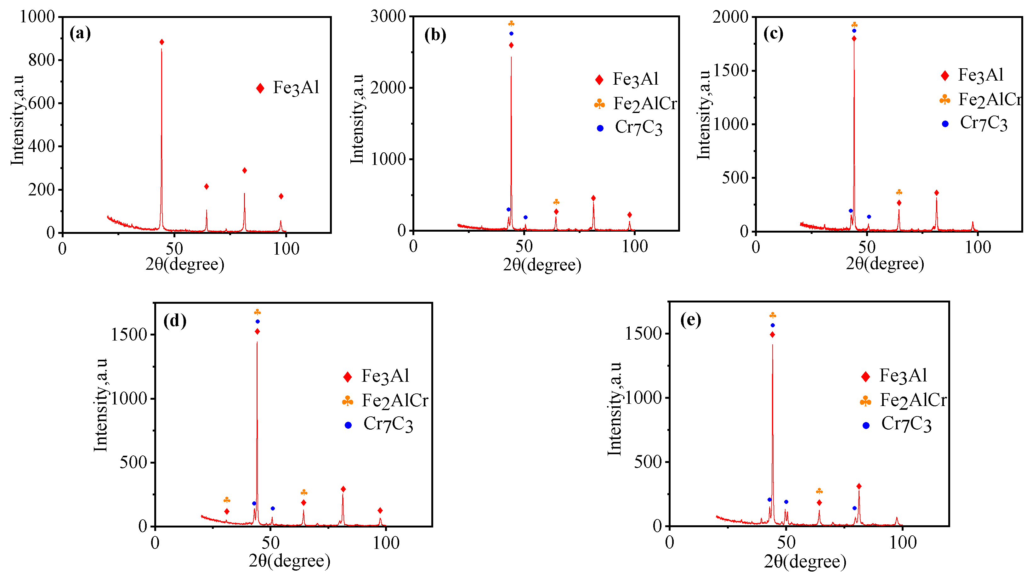
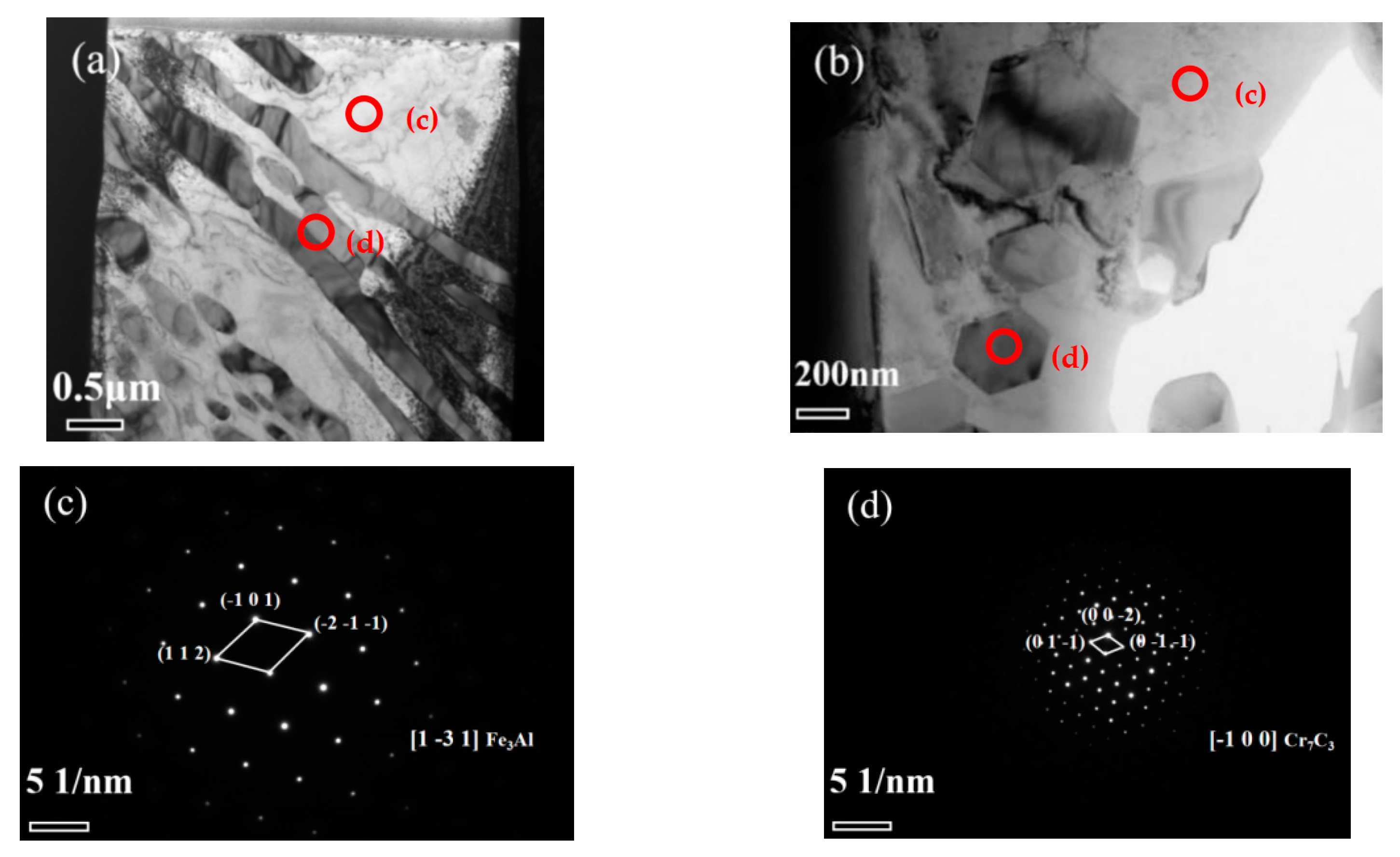
Cr7C3, as a type of carbide, has a high hardness and also represents the strengthening phase of composite cladding materials by which antiwear ability is enhanced. There is no doubt that Cr7C3 has superior wear resistance to Fe2AlCr and Fe3Al. Moreover, the composite cladding material in the friction and wear process can be transformed into the following model: the soft part is the base, and the hard, wear-resistant strengthening phase becomes the particles or stripes embedded in the base. With the progress of friction and wear, the soft Fe3Al and Fe2AlCr phases are gradually worn away and disappear, resulting in the wear-resistant hard phase becoming exposed outside the base material. The exposed hard phase serves as a fulcrum that contacts the friction pair and will be preferentially consumed in the subsequent process until the exposed hard phase is almost worn out. The soft base of the base material will then again come into contact with the friction pair, and the process is repeated. Liu et al. [17] proposed a similar model for the friction and wear mechanism of Ni3Al/Cr3C2. The strengthening phase of the 35 wt.% Cr3C
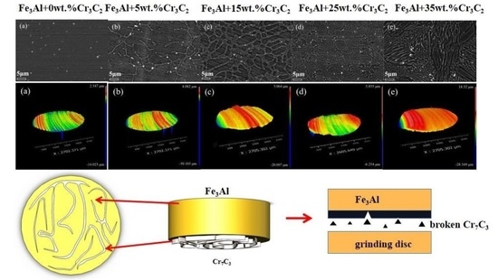
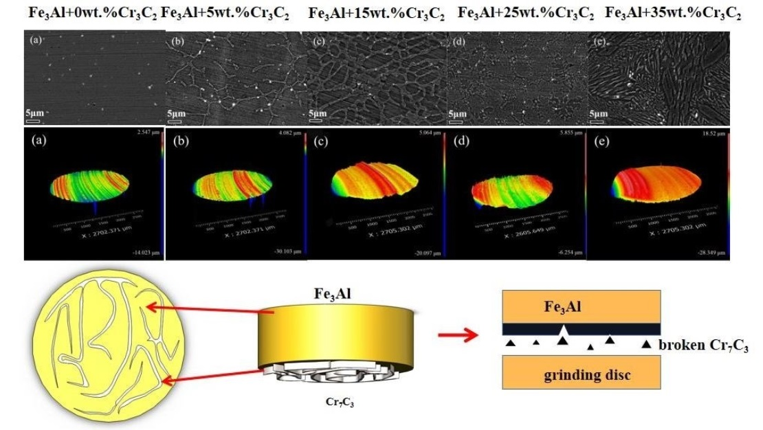
2 cladding layer was found to be block-shaped, whereas in the 5, 15, and 25 wt.% layers, it become reticular. From the wear loss results, we found that, with the exception of the 35 and 5 wt.% Cr3C2 groups, the pin wear rate was similar. Based on the above analysis of friction types, we found that the main friction type of these three groups in the friction process is abrasive wear, which is the main reason for the disappearance of the base material. According to the model, some of the abrasive particles come from the grinding disc and some from the grinding pin, and the part from the pin can be subdivided into Cr7C3 from the strengthening phase and the softer base material. The hardness of the abrasive particles from the disc and the base material part is low, so in the process of abrasive wear, their contribution to the abrasive wear of the pin is very limited; most of the wear loss caused by abrasive wear can be considered to be due to the strengthening phase. Next, the reason for different wear loss caused by differing Cr3C2 content was analyzed.
By comparing the differences between the block-shaped strengthening phase and the reticular strengthening phase, the following two points were found: the size of the block-shaped strengthening phase is much larger than that of the reticular strengthening phase, and from the point of view of carbide content in the whole material, the proportion of the block-shaped strengthening phase is larger than that of the reticular strengthening phase. According to the wear loss data, we found that the wear loss was generally higher for the block-shaped strengthening phase than for the reticular strengthening phase. This indicates that the reticular strengthening phase has advantages in the process of friction and wear because it can also reduce the contact between the grinding surfaces and base material to a certain extent. In addition, the reticular strengthening phase ensures not only higher hardness of the base material, but also a reduced proportion of the hard-phase content and, therefore, generated abrasive particles. From the morphology of the reticular strengthening phase, it is not easy to produce large, hard, abrasive particles.
It can be seen from the SEM morphology of the grinding pin with the 35 wt.% Cr3C2 content that there were many small block pits on the grinding surface. Combined with the strengthening phase morphology photos taken earlier, we found that the block-shaped strengthening phase broke into small pieces and peeled off from the large strengthening phase in the process of friction and wear due to its brittleness. The exfoliated strengthening phase was converted into large, hard, abrasive particles, which greatly exacerbated abrasive wear between the pin and disc. We found that the wear rate of the 35 wt.% Cr3C2 pin was the most serious of all groups. However, the large, hard strengthening phase, which still existed in the pin, could block the wear of abrasive particles in the base material, and high-content strengthening phases also enhanced the strength of the base material, thus representing a double-edged sword [18,19]. Although there were more large, hard, abrasive particles in the grinding pair, the wear rate of the pin was still not very large, and the ability to resist the wear of abrasive particles was stronger than in other groups.
Next, the cladding layers with 15 and 25 wt.% Cr3C2 content were analyzed. Since the strengthening phase shape was a network of fine strips and dots, in the process of friction and wear, the exfoliated strengthening phase did not produce large particles, only small or slender ones. Compared with the 35 wt.% Cr3C
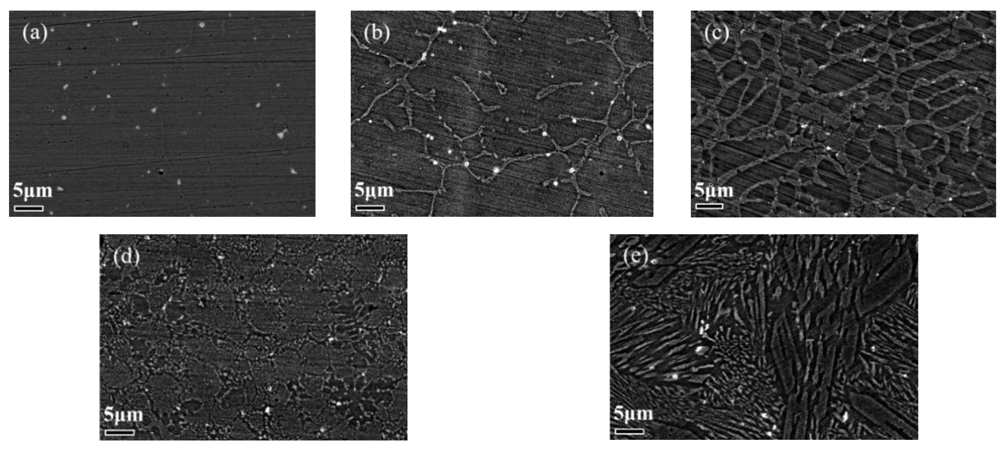
2 cladding layer, there was less hard phase contained in the 15 and 25 wt.% cladding layers when the same volume material was worn away, and the hard-phase content was lower when introduced to the friction pair. As a result, the cladding layer was less prone to serious abrasive wear, and there was less wear loss through abrasive wear on the cladding layer. This further reduced the content of hard, abrasive particles in the grinding pair, forming a virtuous cycle and reducing the wear rate of the cladding layer. From the BSE morphology (Figure 3), it was found that the cladding layer with 25 wt.% Cr3C2 was almost covered with a fine, striated, and dotted strengthening phase. Such a fine, dispersive strengthening phase can cause the matrix to separate from the grinding pair more smoothly, so as to better resist abrasive wear. The 25 wt.% Cr3C2 cladding layer also had higher hardness than the 15 wt.% Cr3C2 cladding layer, factors that led to its higher wear resistance. The layer produced less hard-phase abrasive particles, reducing the wear loss of the grinding disc.
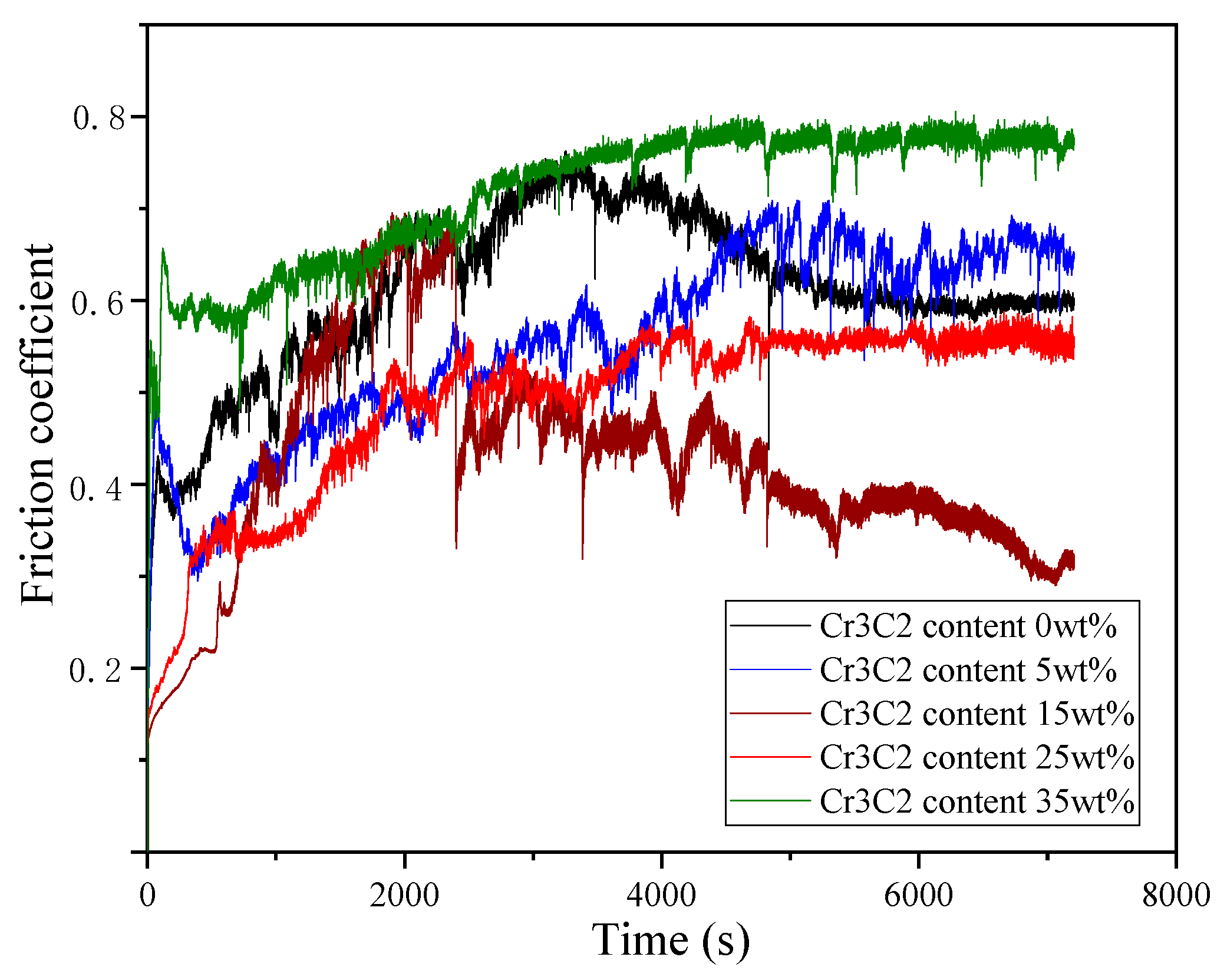
The wear rate of the 5 wt.% Cr3C2 cladding layer was the highest among all Cr3C2 content groups. We found that not only abrasive wear, but also adhesive wear occurred. Adhesive wear is more likely to occur in materials with good plasticity than in brittle materials. Although the cladding layers with 15 and 25 wt.% Cr3C2 content had better plasticity, there was no obvious adhesive wear because most of the base material was isolated from friction by the carbide strengthening phase exposed after wear. However, in the cladding layer with 5 wt.% Cr3C2, the distribution of the strengthening phase was sparse, and the content was small. The base material of the cladding layer could not be well isolated from the grinding disc, and they remained in contact with each other over a large area, resulting in serious adhesive wear. The occurrence of adhesive wear also explains the instability of the friction coefficient in the process of friction and wear (Figure 7).
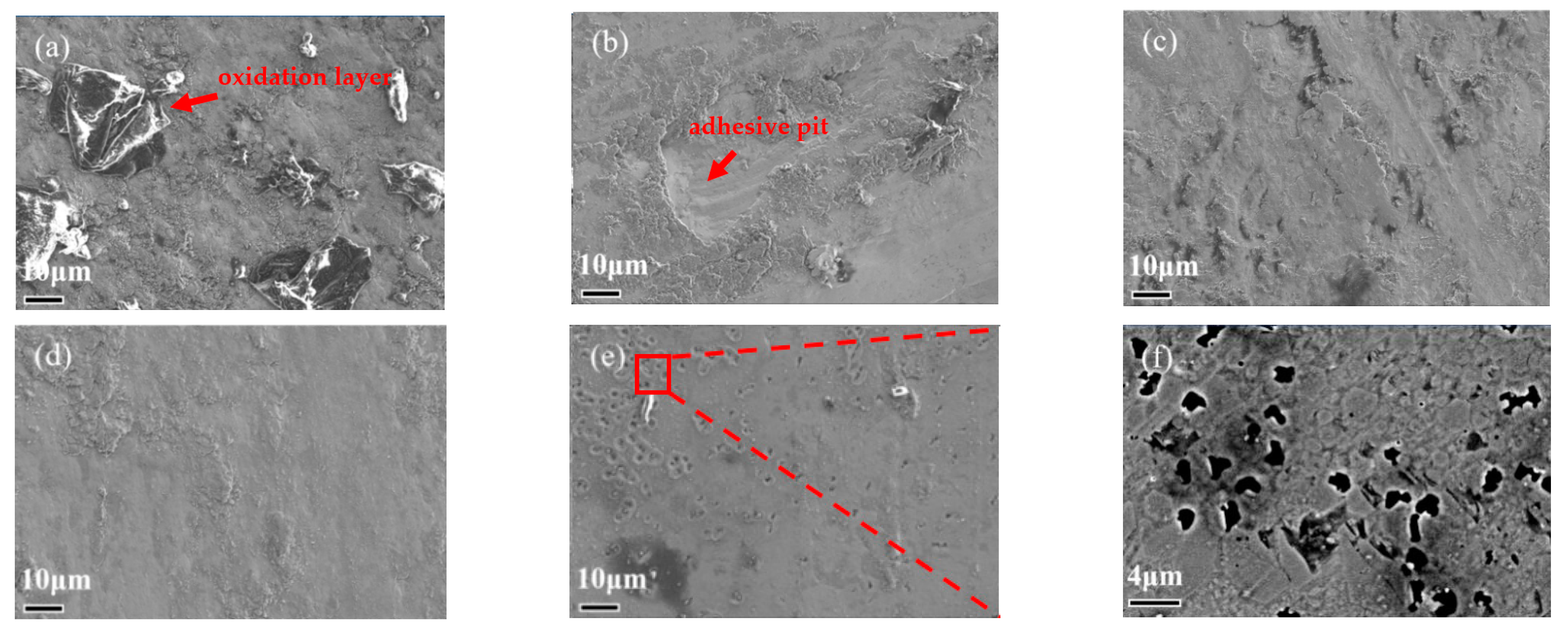
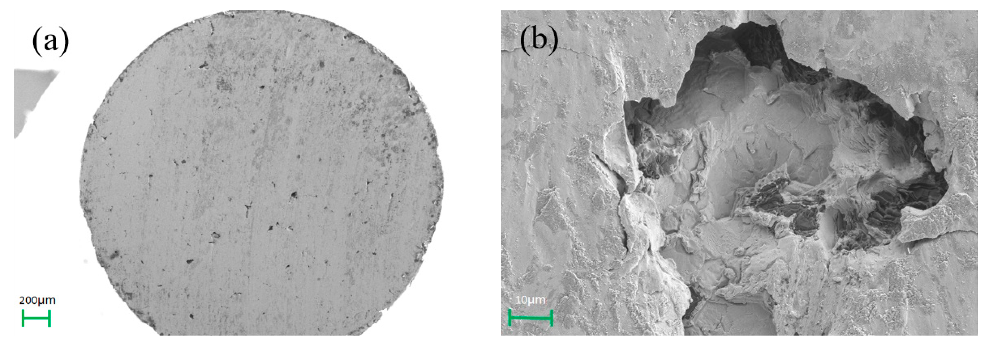
The vermicular cast iron group also showed serious adhesive wear. Figure 11a,b show the surface morphology after wear, where obvious adhesive pits are observed on the grinding pin surface, and more materials were pulled off, resulting in a significant wear rate of the grinding pin. Compared with the Fe3Al material, vermicular cast iron has lower hardness and is closer to the grinding disc in composition, resulting in more serious adhesive wear.
The cladding layer with 0 wt.% Cr3C2 content did not contain Cr3C2, so the isolating friction pair mentioned above was not relevant to the wear reduction mechanism. Therefore, a large area of the Fe3Al base material was in direct contact with the grinding disc and was also the reason for the relatively severe oxidative wear on the surface. With the wear of the oxide layer, the oxide layer falls off and adheres to the cladding layer.

5. Conclusions

In this paper, through wear tests, the friction coefficient and wear rate of cladding layers with different Cr3C2 content were obtained. The friction mechanism was further judged by white light interference, SEM, BSE observation, and EDS analysis. The friction and wear mechanisms were obtained by combining the test results with the microstructure. The microstructure and wear resistance of the cladding layers were affected not only by the factor of Cr3C2 content, but also by the cladding process parameters. The influence of process parameters on the microstructure and wear resistance of the cladding layer were subsequently studied and resulted in the following observations and conclusions.
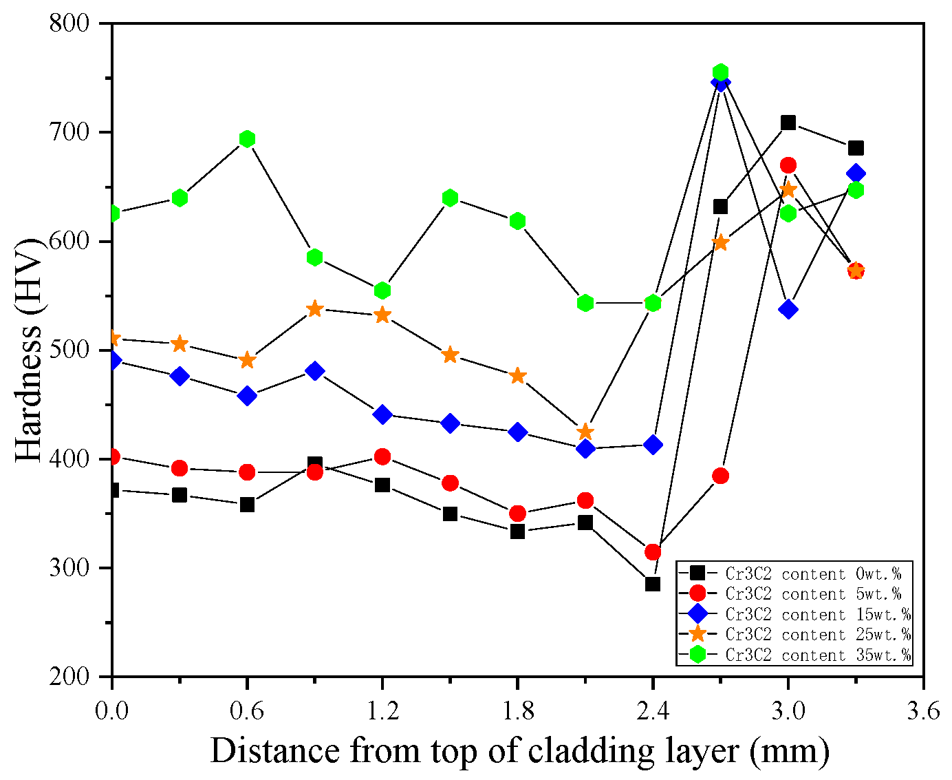
(1) With the increase in Cr3C2 content, the number of cracks in the Fe3Al cladding layer first decreased and then increased, and the 15 and 25 wt.% Cr3C2 cladding layers had the fewest number of cracks. In terms of hardness, it also increased gradually with the increase in Cr3C2 content in the cladding powder and remained relatively stable inside the cladding layer.
(2) With the increase in Cr3C2 content, the morphology of the strengthening phase in the cladding layer changed from a sparse to a dense reticular structure and, finally, to a large block-shaped structure.
(3) For cladding layers prepared using the same process and different Cr3C2 content, the group with the smallest friction coefficient was found to be the 15 wt.% Cr3C2 cladding layer, with large friction coefficients determined for the remaining groups. In terms of wear rate, the lowest values were found for the 15 and 25 wt.% Cr3C2 cladding layers. Compared with cast iron, the Fe3Al/Cr3C2 cladding layer had obvious advantages in various indices.
(4) Judging by the visible furrows on the pin surface, abrasive and oxidative wear appeared in all groups. Adhesive wear only occurred in the pin with 5 wt.% Cr3C2 content. The occurrence of adhesive wear or more serious abrasive wear will lead to greater wear.
(5) The friction and wear mechanisms were determined to be as follows: The relatively soft Fe3Al base material is first worn away, and the harder carbide supports the grinding surface to reduce friction. Then, the carbide gradually disappears from the pin and is transformed into hard-phase particles. The morphology and distribution of the strengthening phase in the cladding layer play an important role in wear resistance. Compared with the block-shaped strengthening phase, the reticular strengthening phase has more advantages; while ensuring higher base material strength, it reduces the proportion of hard particles and size of the hard phase.

Author Contributions

Methodology, J.S. and L.Z.; formal analysis, Y.F.; investigation, Y.F. and Z.L.; resources, L.Z.; writing—original draft preparation, Y.F.; writing—review and editing, K.G. and C.L.; visualization, Y.F. and Z.L.; supervision, J.S. and L.Z.; project administration, L.Z.; funding acquisition, L.Z. All authors have read and agreed to the published version of the manuscript.

Funding

This work was supported by the National Key R&D Program of China, grant number 2020YFE0200900.

Institutional Review Board Statement

Not applicable.

Informed Consent Statement

Not applicable.

Data Availability Statement

All data that support the findings of this study are included within the article.

Conflicts of Interest

The authors declare no conflict of interest.

Nomenclature

SEMScanning Electron Microscopy
TEMTransmission Electron Microscopy
FIBFocused Ion Beam
XRDX-ray Diffraction
BSEBackscattered Electron

References

  1. Yin, Y.; Li, J.; Ma, H. Friction and wear properties of sintered Fe3Al intermetallic compound based friction materials. Tribology 2004, 24, 457–461. [Google Scholar]
  2. McKamey, C.G.; DeVan, J.H.; Tortorelli, P.F.; Sikka, V.K. A review of recent developments in Fe3Al-based alloys. J. Mater. Res. 1991, 6, 1779–1805. [Google Scholar] [CrossRef] [Green Version]
  3. Stoloff, N.S. Iron aluminides: Present status and future prospects. Mater. Sci. Eng. A 1998, 258, 1–4. [Google Scholar] [CrossRef]
  4. Stoloff, N.S.; Liu, C.T.; Deevi, S.C. Emerging applications of intermetallics. Intermetallics 2000, 8, 1313–1320. [Google Scholar] [CrossRef]
  5. Chen, Y.; Wang, H.M. Microstructure and wear resistance of laser clad TiC reinforced FeAl intermetallic matrix composite coatings. Surf. Coat. Technol. 2003, 168, 30–36. [Google Scholar] [CrossRef]
  6. Zhang, J.; Zhang, X.; He, Z.; Hao, X.; Wang, Y.; Li, J. Application of Nano-sized Fe3Al/Al2O3 gradient coating on Steel Plate by laser cladding method. Paint. Ind. 2019, 42, 61–64. [Google Scholar]
  7. Zhao, X. Study on Microstructure and Wear Resistance of Laser Cladding Ni3Al/Cr3C2 Composite. Master’s Thesis, Hebei University of Technology, Tianjin, China, 2019. [Google Scholar]
  8. Chen, C.; Zhao, X.; Fang, Q.; Zhao, L.; Han, W.; Peng, Y.; Yin, F.; Tian, Z. Wear Resistance of Laser Cladding Ni3Al/Cr3C2 Composites. Rare Met. Mater. Eng. 2020, 49, 1388–1394. [Google Scholar]
  9. Li, M.; Han, B.; Song, L.; He, Q. Enhanced surface layers by laser cladding and ion sulfurization processing towards improved wear-resistance and self-lubrication performances. Appl. Surf. Sci. 2020, 503, 144226. [Google Scholar] [CrossRef]
  10. Hemmati, I.; Ocelík, V.; De Hosson, J.T.M. Effects of the alloy composition on phase constitution and properties of laser deposited Ni-Cr-B-Si coatings. Phys. Procedia 2013, 41, 302–311. [Google Scholar] [CrossRef] [Green Version]
  11. Xu, B.; Guo, F. A micromechanics method for transverse creep behavior induced by interface diffusion in unidirectional fiber-reinforced metal matrix composites. Int. J. Solids Struct. 2019, 159, 126–134. [Google Scholar] [CrossRef]
  12. Colaço, R.; Vilar, R. Abrasive wear of metallic matrix reinforced materials. Wear 2003, 255, 643–650. [Google Scholar] [CrossRef]
  13. Mendiratta, M.G.; Ehlers, S.K.; Chatterjee, D.K.; Lipsitt, H.A. Tensile Flow and Fracture Behavior of DO3 and Fe—25 at.% Al and Fe—31 at.% Al Alloys. Metall. Trans. A 1987, 18, 283–291. [Google Scholar] [CrossRef]
  14. Li, Z.; Peng, B. Formation mechanism and control measures of laser cladding cracks. J. Mater. Prot. 2016, 49, 61–66. [Google Scholar]
  15. Zhao, Z. Wear of Engine Cylinder Liner and Its Preventive Measures. J. North China Inst. Aerosp. Technol. 2005, 15, 14–15. [Google Scholar]
  16. Gao, C. The Relationship between Hardness and Wear Resistance of Metals. Mech. Eng. 1981, 4, 6–8. [Google Scholar]
  17. Liu, Z.; Yin, F.; Chen, C.; Zhao, L.; Fu, L.; Feng, Y.; Cao, Y.; Peng, Y.; Tian, Z.; Li, C. Microstructure and Wear Resistance of a Cr7C3 Reinforced Ni3Al Composite Coating Prepared by Laser Cladding. Coatings 2022, 12, 105. [Google Scholar] [CrossRef]
  18. Yuan, Y.; Li, Z. Effects of rod carbide size, content, loading and sliding distance on the friction and wear behaviors of (Cr, Fe)7C3 reinforced α-Fe based composite coating produced via PTA welding process. Surf. Coat. Technol. 2014, 248, 9–22. [Google Scholar] [CrossRef]
  19. Hu, J.; Li, D.; Llewellyn, R. Computational investigation of microstructural effects on abrasive wear of composite materials. Wear 2005, 259, 6–17. [Google Scholar] [CrossRef]
Figure 1. Laser cladding system: (a) KUKA robotic arm, (b) YLS-6000 fiber laser, and (c) powder feeder.
Coatings 12 01980 g001
Figure 2. BSE morphology of cladding layers prepared using the same process and different Cr3C2 content: (a) 0 wt.%, (b) 5 wt.%, (c) 15 wt.%, (d) 25 wt.%, and (e) 35 wt.%.
Coatings 12 01980 g002
Figure 3. XRD spectra of cladding layers prepared using the same process and different Cr3C2 content: (a) 0 wt.%, (b) 5 wt.%, (c) 15 wt.%, (d) 25 wt.%, and (e) 35 wt.%.
Coatings 12 01980 g003
Figure 4. TEM morphology and selected electron diffraction patterns of 15 and 35 wt.% Cr3C2 cladding layers. Microstructure morphology of (a) 15 wt.% Cr3C2 cladding layer and (b) 35 wt.% Cr3C2 cladding layer. Diffraction patterns of (c) Fe3Al/Fe2AlCr in the [1–31] crystal band direction and (d) Cr7C3 in the [−100] crystal band direction.
Coatings 12 01980 g004
Figure 5. Friction coefficient curves of vermicular graphite cast iron and cladding layers with the same process and different Cr3C2 content.
Coatings 12 01980 g005
Figure 6. Repeated-test friction coefficient curves of 5 wt.% Cr3C2 cladding layer.
Coatings 12 01980 g006
Figure 7. Microhardness of the cladding layers with different Cr3C2 content.
Coatings 12 01980 g007
Figure 8. Three-dimensional profiles after wear of grinding pins prepared using the same process and different Cr3C2 content: (a) 0 wt.%, (b,f) 5 wt.%, (c) 15 wt.%, (d) 25 wt.%, and (e) 35 wt.%.
Coatings 12 01980 g008
Figure 9. SEM morphology of grinding pin surfaces prepared using the same process and different Cr3C2 content: (a) 0 wt.%, (b) 5 wt.%, (c) 15 wt.%, (d) 25 wt.%, and (e,f) 35 wt.%.
Coatings 12 01980 g009
Figure 10. BSE morphology of the longitudinal section of a grinding pin with 0 wt.% Cr3C2 content captured at (a) low power and (b) high power.
Coatings 12 01980 g010
Figure 11. Overall surface morphology of vermicular cast iron after wear, captured at (a) low power and (b) high power.
Coatings 12 01980 g011
Table 1. Chemical composition of Fe3Al powder (wt.%).
AlBCrFeMnNiZr
15.230.115.7876.820.0520.540.26
Table 2. The number of cracks generated in samples of different cladding materials of the same length (15 cm).
GroupNumber of Cracks
0 wt.% Cr3C2 cladding layer6
5 wt.% Cr3C2 cladding layer5
15 wt.% Cr3C2 cladding layer0
25 wt.% Cr3C2 cladding layer0
35 wt.% Cr3C2 cladding layer6
Table 3. Wear loss of 5 wt.% Cr3C2 cladding layer in repeated tests.
First TestSecond TestThird Test
Pin wear rate
(1 × 10⁻⁵ mm3/N·m)
0.9101.0171.203
Disc wear loss (g)0.002270.002010.00283
Table 4. Pin and disc wear loss of different pin material groups.
Pin MaterialDisc Wear Loss (g)Pin Wear Rate (1 × 10⁻⁵ mm3/N·m)
0 wt.% Cr3C2 cladding layer0.002470.514
5 wt.% Cr3C2 cladding layer0.002011.017
15 wt.% Cr3C2 cladding layer0.002390.396
25 wt.% Cr3C2 cladding layer0.000740.285
35 wt.% Cr3C2 cladding layer0.009610.964
Vermicular graphite cast iron0.002273.102
Publisher’s Note: MDPI stays neutral with regard to jurisdictional claims in published maps and institutional affiliations.

