
High-Temperature Solid Particle Erosion of Aerospace Components: Its Mitigation Using Advanced Nanostructured Coating Technologies

Abstract
:1. Introduction
1.1. Solid Particle Erosion
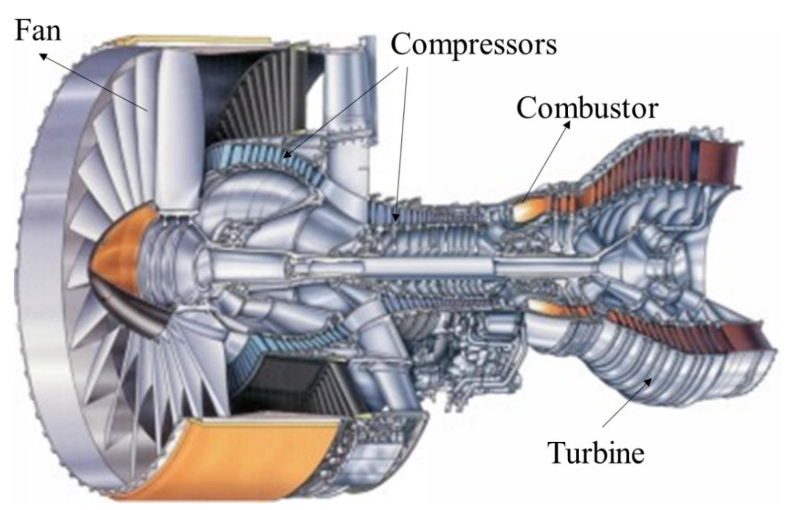
1.2. Gas Turbine Engines and Solid Particle Erosion
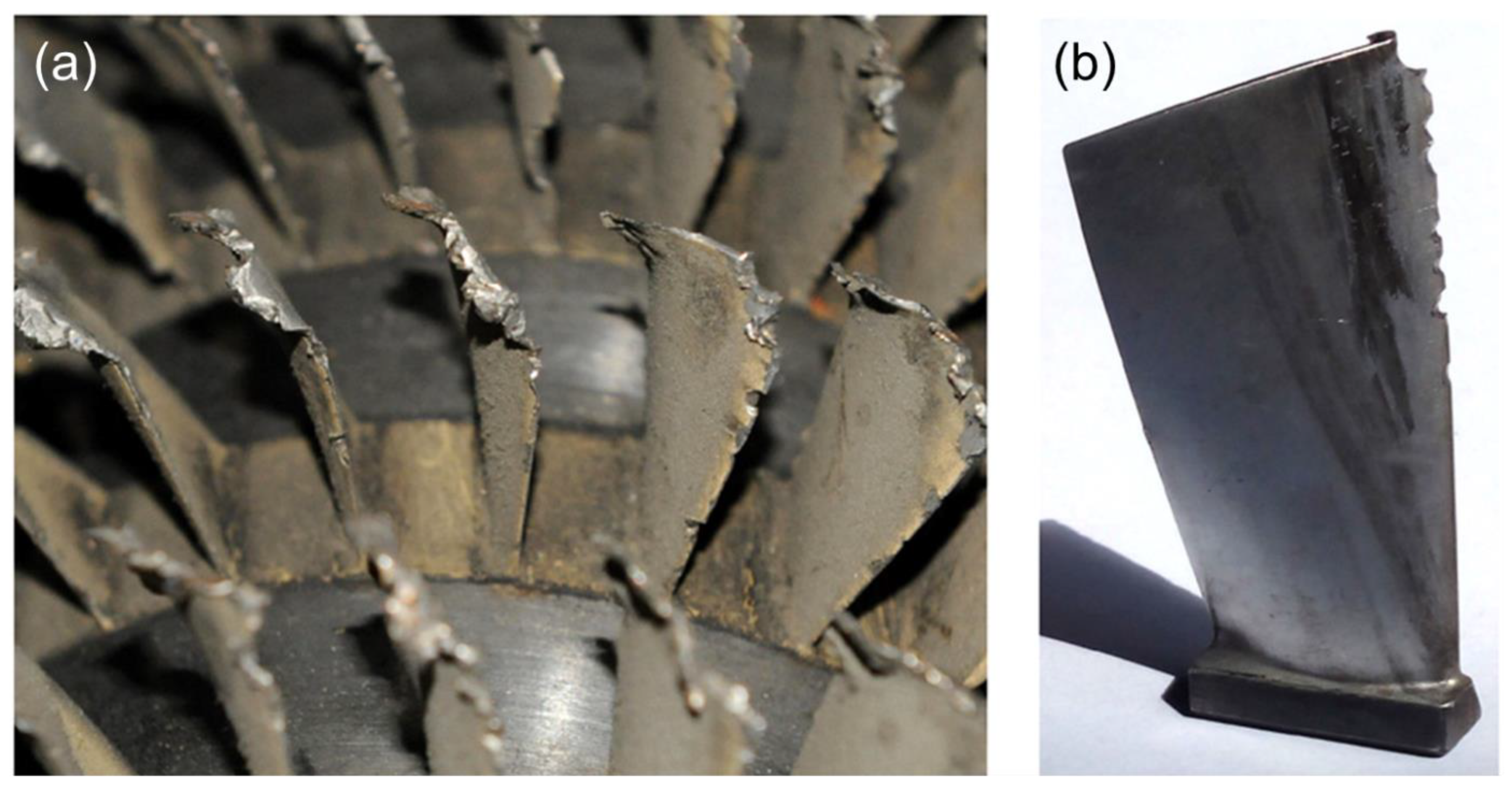
1.2.1. Erosion of Compressor Blades by Sand Particles
1.2.2. Erosion by Volcanic Ash
1.3. Overview of Solid Particle Erosion Studies and Possible Solutions
2. Temperature-Dependent Solid Particle Erosion of Metals and Ceramics
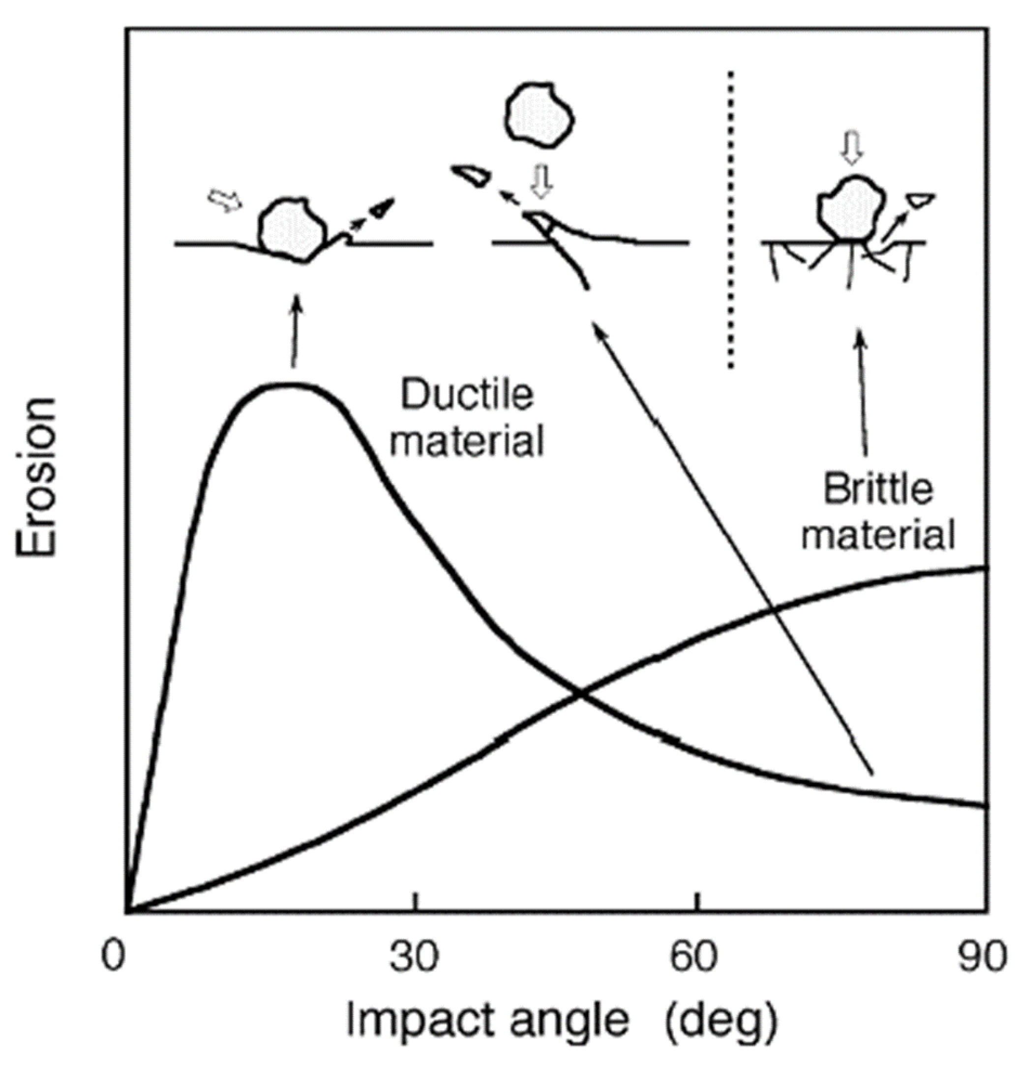
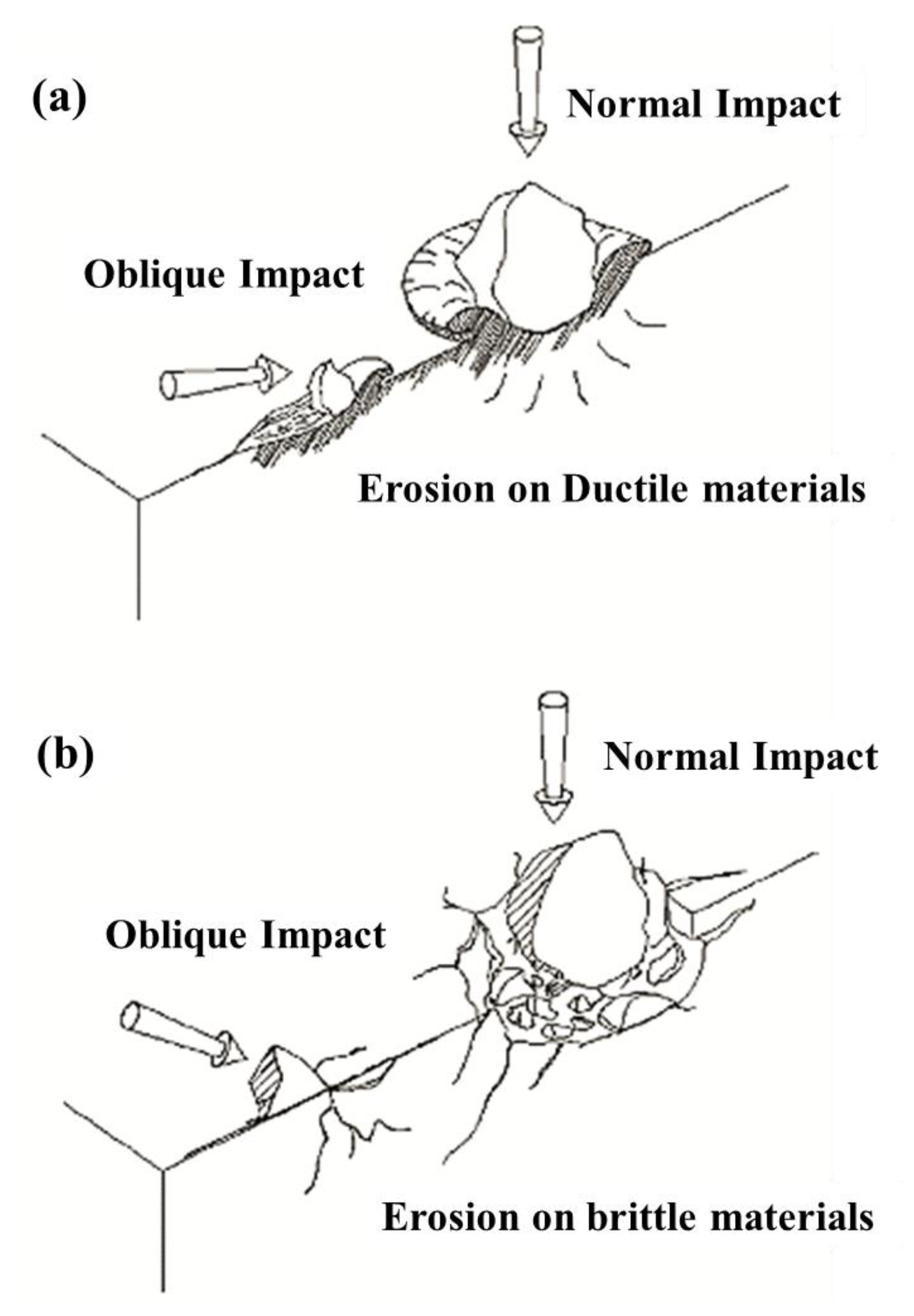
2.1. Ductile or Metallic Materials and High-Temperature SPE Models
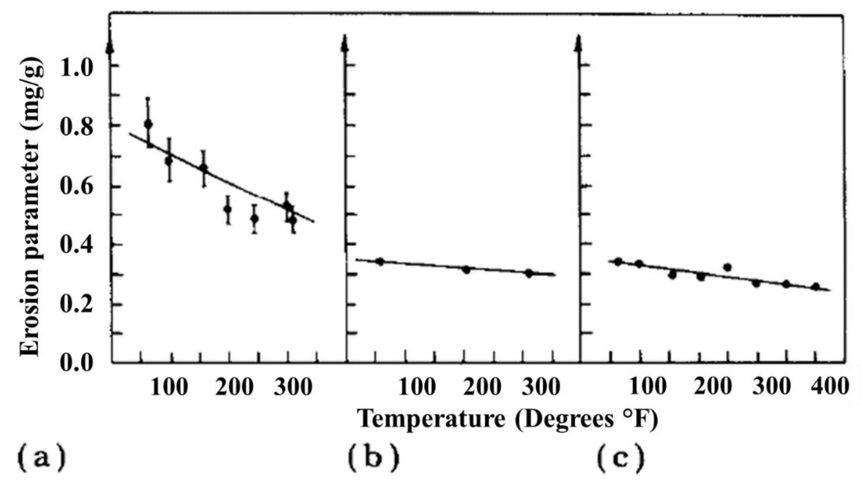
2.1.1. Erosion Rate Trend with Increasing Temperature
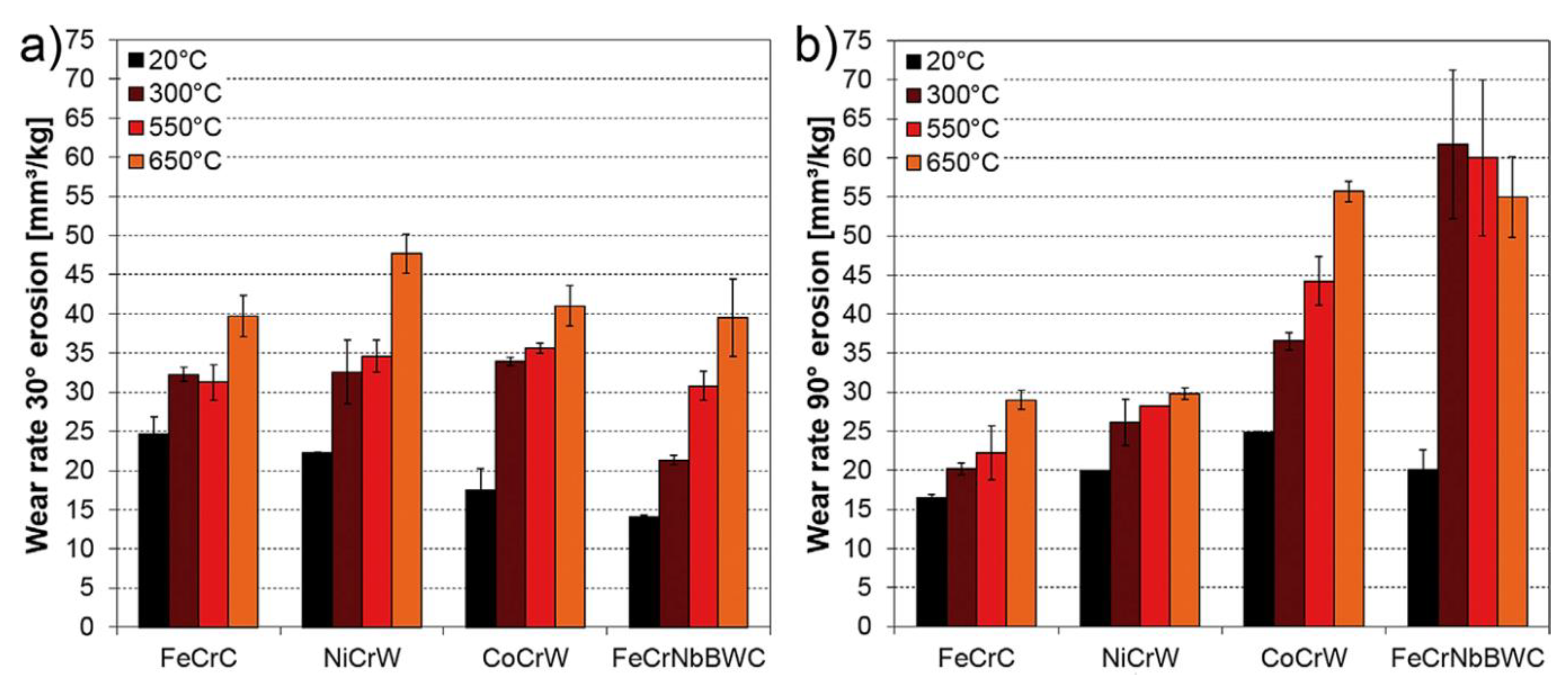
2.1.2. High-Temperature SPE Tests in a Corrosive Environment
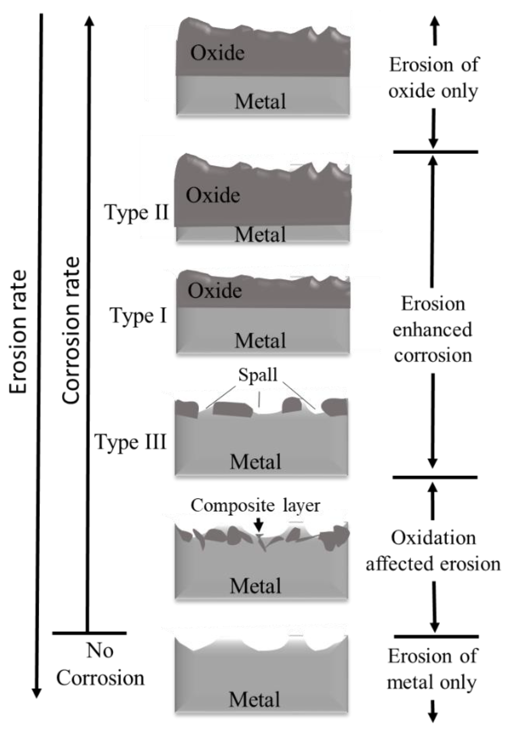
2.1.3. Role of Oxidation in High-Temperature SPE
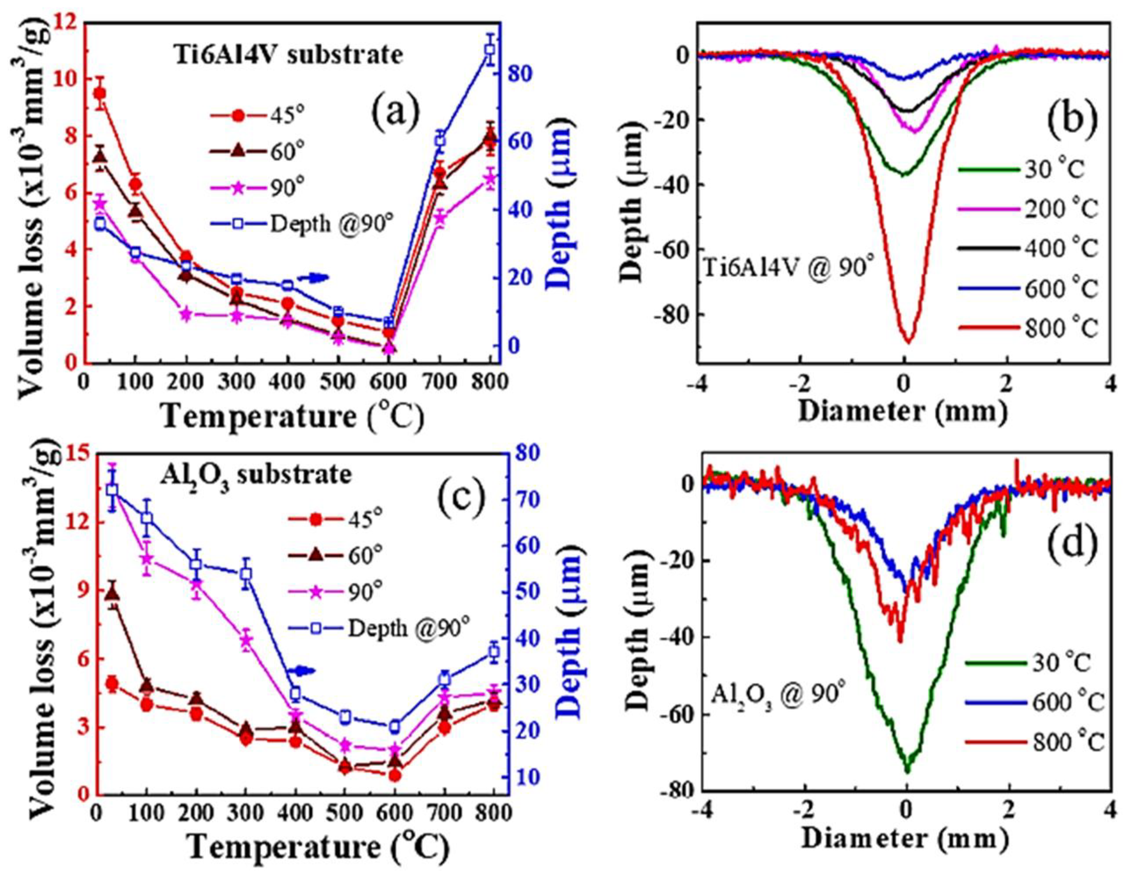
- Metal erosion: Most metal alloys do not get oxidized at low temperatures (<400 °C). In this scenario, the erosion mechanism is similar to the ambient conditions and follows a plastic cutting mechanism. Even though there is oxidation, the oxide layer should be thin, and it deforms similarly to the substrate. The erosion rate is thus higher at lower impact angles compared to normal impact. In this region, the erosion rate can be reduced for a given material if the critical strain for localization is reduced (Figure 8).
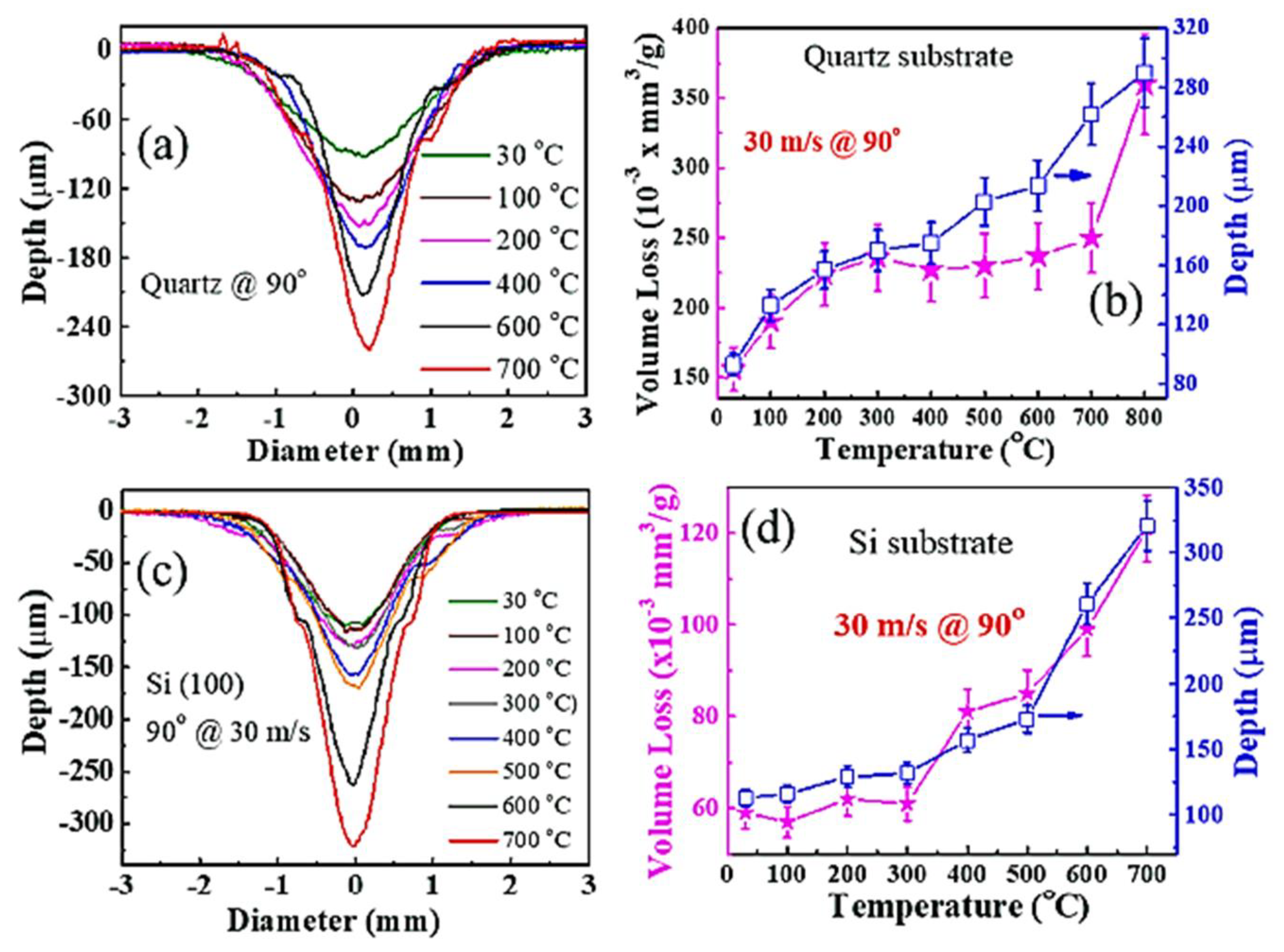
- Oxidation affects erosion: When the temperature is in an intermediate range and the impact velocity and particle feed rate are moderate, an oxide layer of medium thickness is formed. During the SPE, the depth of deformation due to the impact of erodent particles goes beyond the oxide layer thickness and reaches the metallic substrate. As a result, the oxide layer is broken, and the softer metal comes out and mixes with the metal oxide flakes, forming a composite layer. Subsequent impacts thus cause the removal of composite material. Thus, this oxidation-affected erosion is converted from a ductile to a brittle erosion mechanism depending on the thickness of the oxide layer (Figure 8).
- Oxidation-controlled erosion: At higher temperatures (700 to 900 °C) with low erodent velocities and particle feed rates, the oxide layer grows to a certain critical thickness. However, the layer is brittle and not so adherent, resulting in easy spallation (Figure 8).
- Oxide erosion: In the case of very high temperatures (>800 °C) during erosion testing, a thick oxide layer is formed on the metallic material’s surface even at low impact velocities and particle feed rates. In this case, the deformation takes place only in the oxidized layer, and the metal underneath does not involve itself in the erosion process. As a result, material removal follows a brittle fracture mechanism. Since the adhesion of the oxide layer to the substrate is weak, the erosion rate values are usually high here.
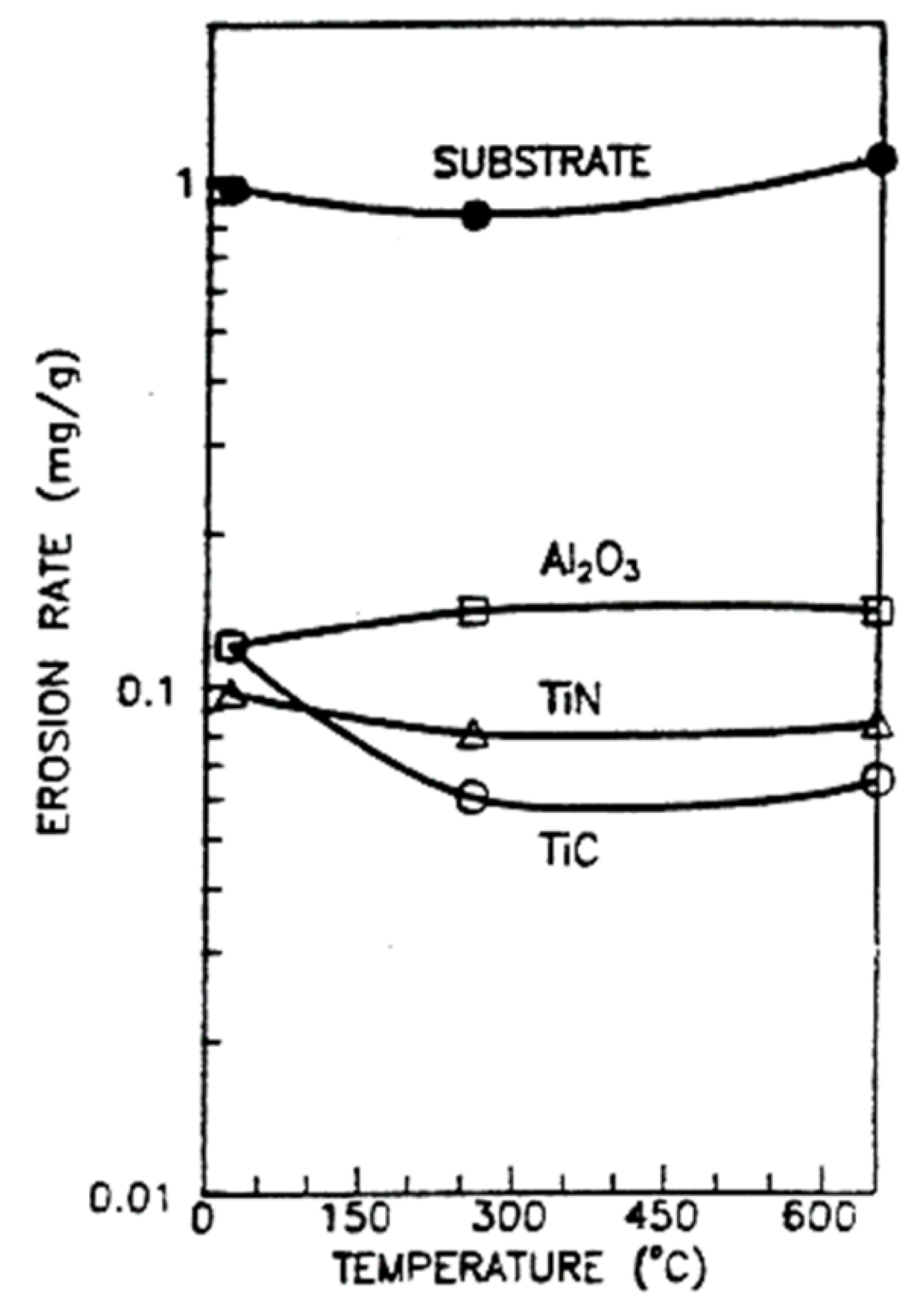
2.1.4. Role of Bonding Nature in High-Temperature SPE
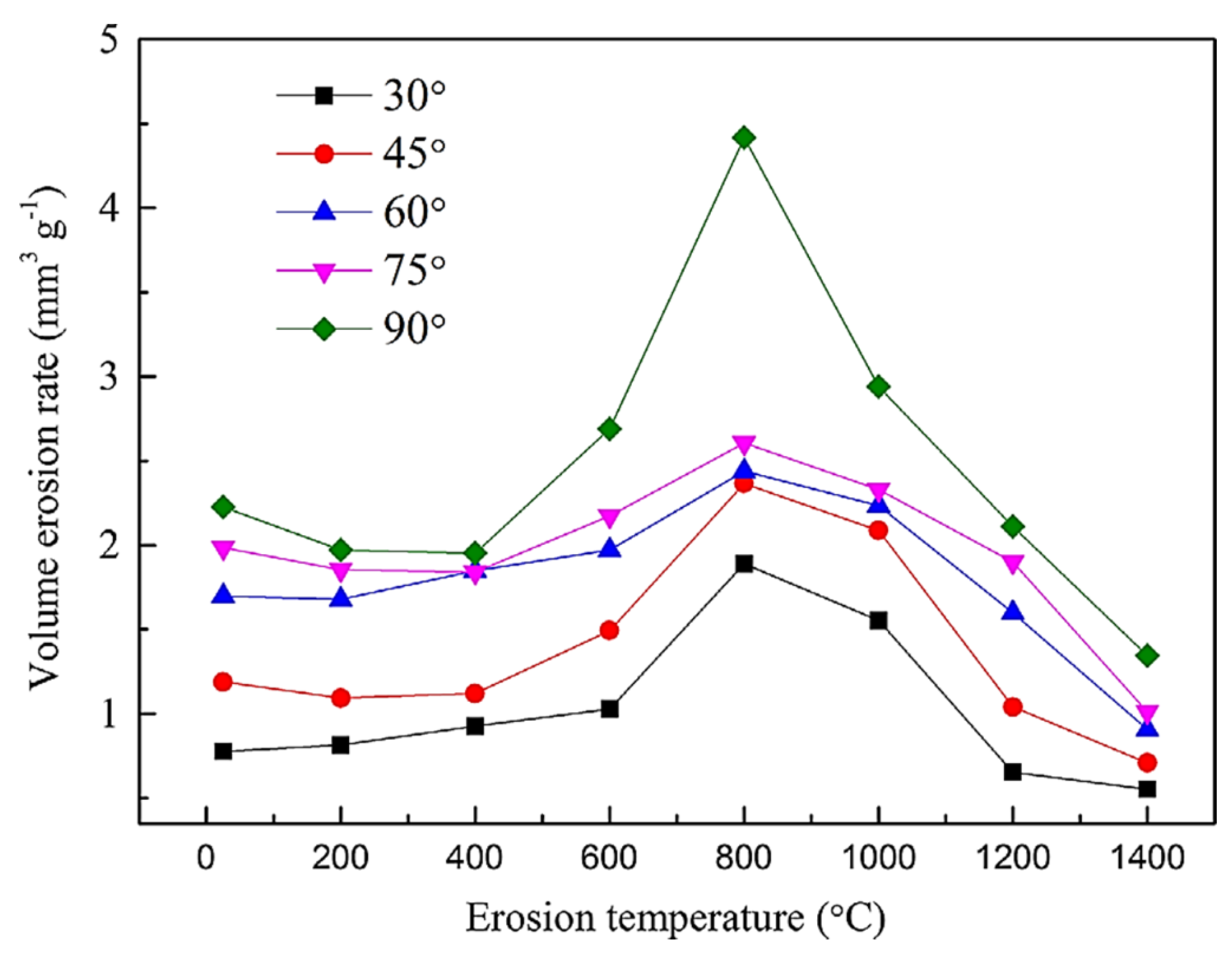
2.2. Solid Particle Erosion of Brittle Materials
3. Protective PVD Coatings for Solid Particle Erosion
3.1. First-Generation Coatings (Single-Phase Coatings)
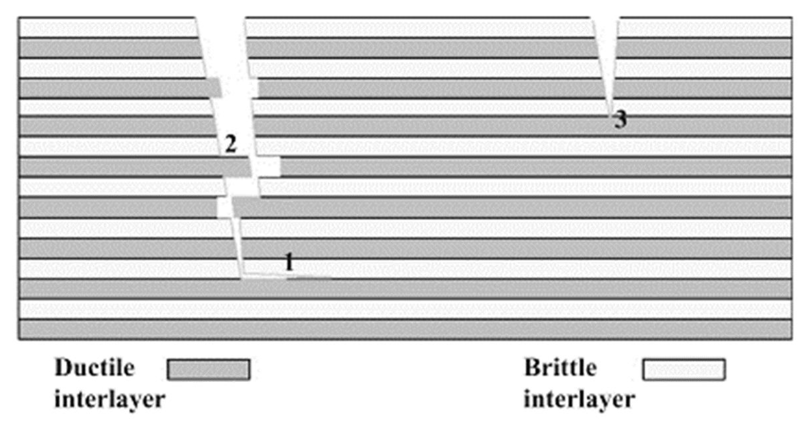
3.2. Second-Generation Coatings (Metal/Ceramic Multilayer Coatings)
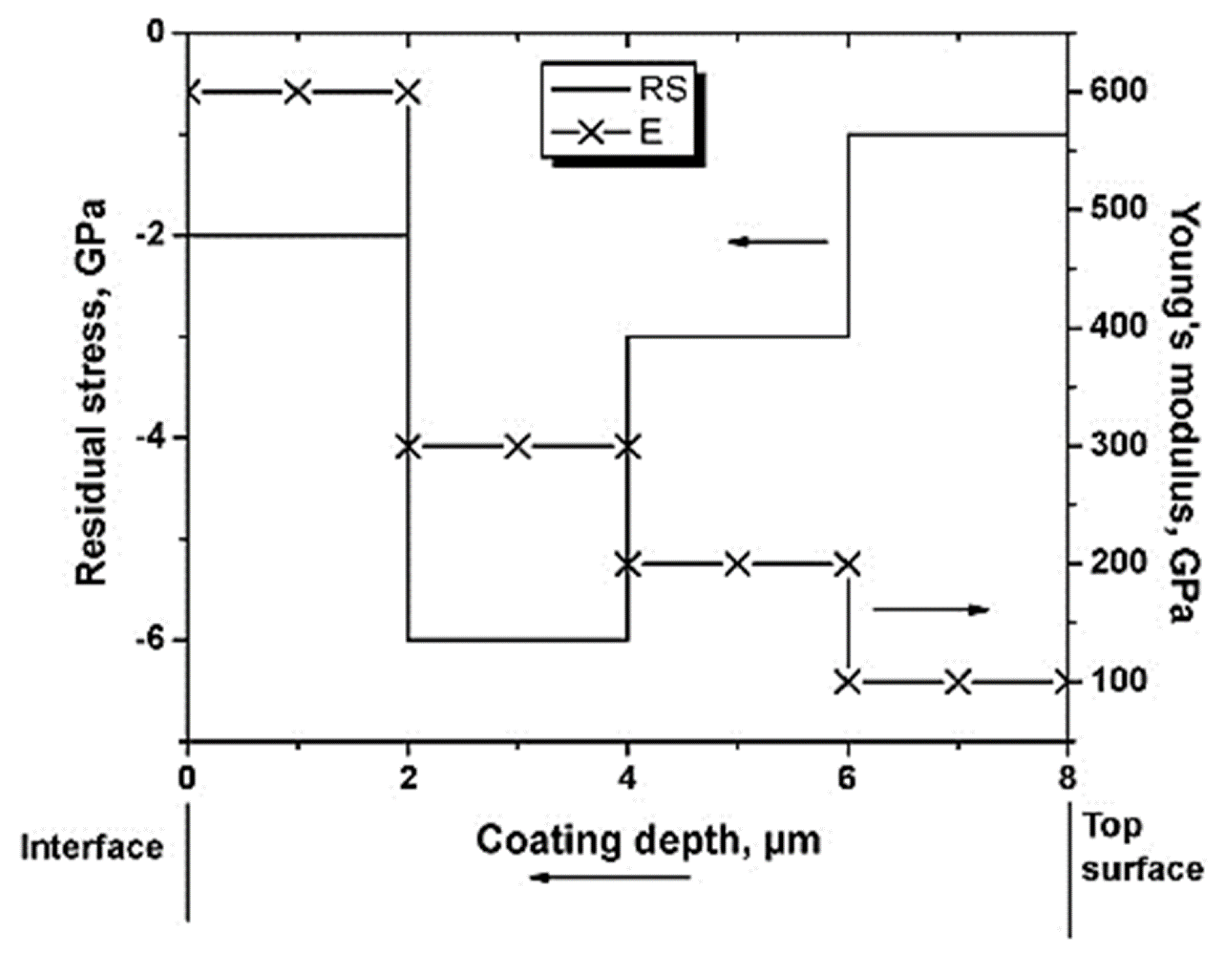
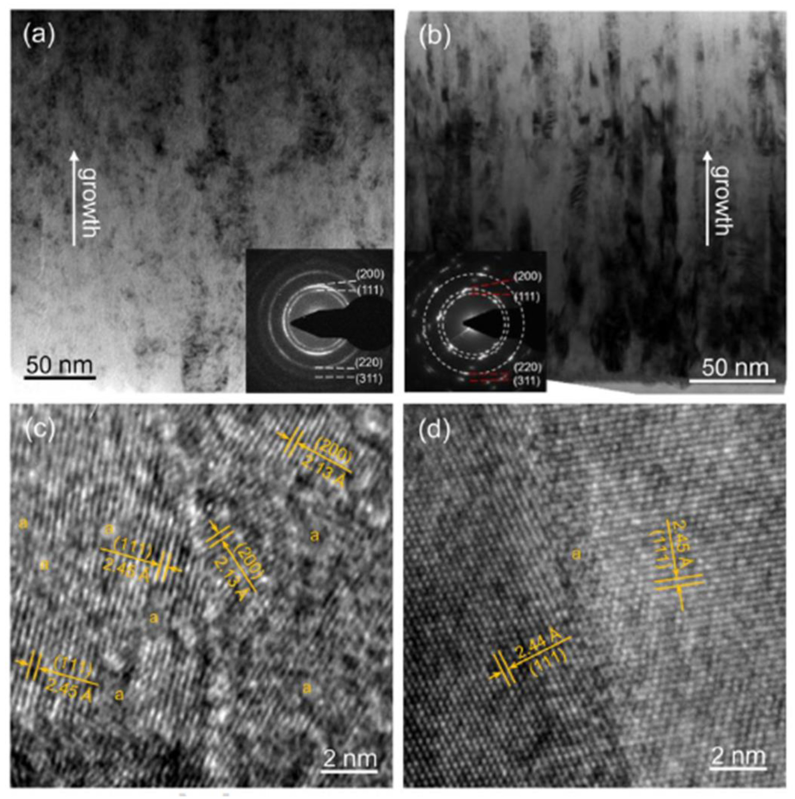
3.3. Third-Generation Coatings (Metal-Ceramic Nanocomposite Coatings and Nanolayered-Multilayer Coatings)
3.4. SPE Resistant Coatings with Energy-Absorbing Nano-Porous Metal Layers
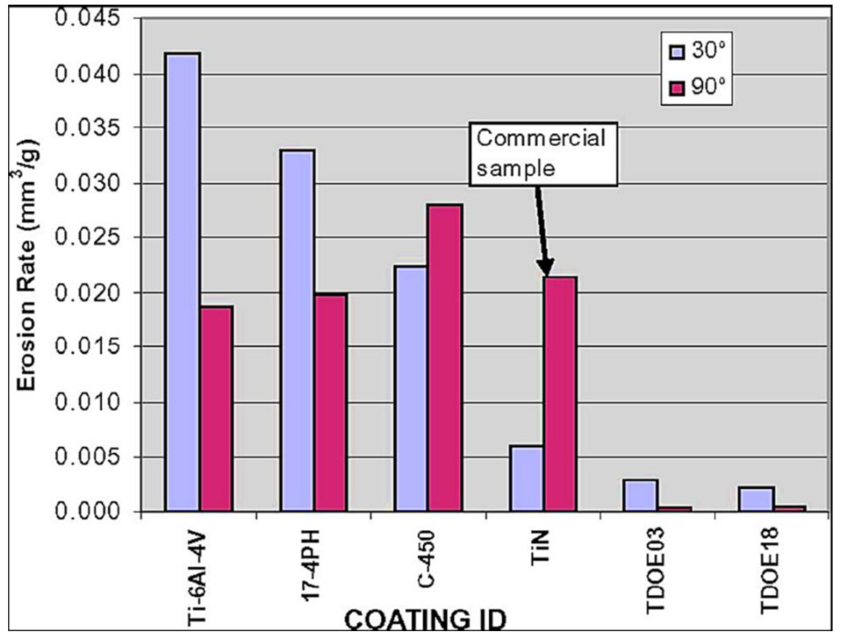
3.5. Notable New Generation Erosion Resistant Coatings
4. Scope for Future Research
- Even though the erosion mechanism is well understood in ductile and brittle materials, the influence of temperature on the erosion process is still not fully established. It is an important aspect because gas turbines are usually operated at high temperatures. Different materials behave differently with increasing temperature in terms of corrosion and mechanical properties. So, more experimental and simulation studies on various aerospace materials are required to establish the role of temperature on the erosion process. These studies will help in choosing suitable materials to develop erosion-resistant coatings for high-temperature aerospace applications.
- Most of the previously reported protective coatings for compressor blades were tested at RT. The erosion resistance performance of the developed protective coatings should be tested at high temperatures so that the tested results match the real conditions of the gas turbine blades.
- Third-generation nanocomposite and nanolayered multi-layered coatings with less than 10 nm grain size proved to perform better against the SPE. However, there is still limited literature available in this area. The development of erosion-resistant nanocoatings with different compositions and architectures can lead to the establishment of potential erosion-resistant coatings.
- Recently, our group reported that the energy-absorbing nanoporous metal layers can be used in erosion-resistant coatings [153]. The coating performance against the SPE significantly improved after introducing the energy-absorbing nanoporous metal layers. More research in this direction should be carried out to improve the efficiency of SPE-resistant coatings.
- Erosion-resistant coatings need higher thickness values (minimum thickness ~ 7 µm) with good mechanical properties. In order to achieve the required coating with low production costs, cost-effective precursor materials, higher growth rate techniques such as cathodic arc, and novel coating designs should be identified.
5. Conclusions
Author Contributions
Funding
Institutional Review Board Statement
Informed Consent Statement
Data Availability Statement
Acknowledgments
Conflicts of Interest
References
- Langston, L.S. Turbines, Gas. In Encyclopedia of Energy; Elsevier: Amsterdam, The Netherlands, 2004; pp. 221–230. ISBN 9780121764807. [Google Scholar]
- Sonntag, R.E.; Borgnakke, C. Introduction to Engineering Thermodynamics, 2nd ed.; John Wiley: Hoboken, NJ, USA, 2006; ISBN 9780471737599. [Google Scholar]
- Finnie, I. Erosion of surfaces by solid particles. Wear 1960, 3, 87–103. [Google Scholar] [CrossRef]
- Bitter, J. A study of erosion phenomena part I. Wear 1963, 6, 5–21. [Google Scholar] [CrossRef]
- Finnie, I. Some observations on the erosion of ductile metals. Wear 1972, 19, 81–90. [Google Scholar] [CrossRef]
- Urban, L.A. Parameter Selection for Multiple Fault Diagnostics of Gas Turbine Engines. J. Eng. Power 1975, 97, 225–230. [Google Scholar] [CrossRef]
- Chena, W.R.; Zhao, L.R. Review—Volcanic ash and its influence on aircraft engine components. Proc. Eng. 2015, 99, 795–803. [Google Scholar] [CrossRef]
- Hamed, A.; Tabakoff, W. (Eds.) 83rd Symposium of Propulsion and Energetics Panel on Turbines; AGARD: Rotterdam, The Netherlands, 1994; p. 11. [Google Scholar]
- Pepi, M.; Squillacioti, R.; Pfledderer, L.; Phelps, A. Solid Particle Erosion Testing of Helicopter Rotor Blade Materials. J. Fail. Anal. Prev. 2011, 12, 96–108. [Google Scholar] [CrossRef]
- Dashtkar, A.; Hadavinia, H.; Sahinkaya, M.N.; A Williams, N.; Vahid, S.; Ismail, F.; Turner, M. Rain erosion-resistant coatings for wind turbine blades: A review. Polym. Polym. Compos. 2019, 27, 443–475. [Google Scholar] [CrossRef]
- Keegan, M.H.; Nash, D.H.; Stack, M.M. Review on erosion issues associated with the leading edge of wind turbine blades. J. Phys. D Appl. Phys. 2013, 46, 383001. [Google Scholar] [CrossRef] [Green Version]
- Veers, P.S.; Ashwill, T.D.; Sutherland, H.J.; Laird, D.L.; Lobitz, D.W.; Griffin, D.A.; Mandell, J.F.; Musial, W.D.; Jackson, K.; Zuteck, M.; et al. Trends in the design, manufacture and evaluation of wind turbine blades. Wind. Energy 2003, 6, 245–259. [Google Scholar] [CrossRef]
- Ashrafizadeh, H.; Mertiny, P.; McDonald, A. Evaluation of the effect of temperature on mechanical properties and wear resistance of polyurethane elastomers. Wear 2016, 368–369, 26–38. [Google Scholar] [CrossRef]
- Gernaat, D.E.H.J.; Bogaart, P.W.; van Vuuren, D.P.; Biemans, H.; Niessink, R. High-resolution assessment of global technical and economic hydropower potential. Nat. Energy 2017, 2, 821–828. [Google Scholar] [CrossRef] [Green Version]
- Darmawi; Sipahutar, R.; Bernas, S.M.; Imanuddin, M.S. Renewable energy and hydropower utilization tendency worldwide. Renew. Sustain. Energy Rev. 2012, 17, 213–215. [Google Scholar]
- Killingtveit, Å. 15-Hydroelectric Power. In Future Energy, 3rd ed.; Letcher, T.M., Ed.; Elsevier: Amsterdam, The Netherlands, 2020; pp. 315–330. [Google Scholar]
- Koirala, R.; Zhu, B.; Neopane, H.P. Effect of guide vane clearance gap on Francis turbine performance. Energies 2016, 9, 275. [Google Scholar] [CrossRef]
- Mann, B. High-energy particle impact wear resistance of hard coatings and their application in hydroturbines. Wear 2000, 237, 140–146. [Google Scholar] [CrossRef]
- Liu, J.; Lu, L.; Zhu, L. Experiment study on sediment erosion of Pelton turbine flow passage component material. IOP Conf. Series Earth Environ. Sci. 2012, 15, 032055. [Google Scholar] [CrossRef]
- Bousser, E.; Martinu, L.; Klemberg-Sapieha, J. Solid particle erosion mechanisms of protective coatings for aerospace applications. Surf. Coat. Technol. 2014, 257, 165–181. [Google Scholar] [CrossRef] [Green Version]
- Finnie, I.; Wolak, J.; KabiI, Y. Erosion of metals by solid particles. J. Mater. 1967, 2, 682–700. [Google Scholar]
- Goodwin, J.E.; Sage, W.; Tilly, G.P. Study of erosion by solid particles. Proc. Inst. Mech. Eng. 1969, 184, 279–292. [Google Scholar] [CrossRef]
- Winter, R.; Hutchings, I. Solid particle erosion studies using single angular particles. Wear 1974, 29, 181–194. [Google Scholar] [CrossRef]
- Feuerstein, A.; Kleyman, A. Ti–N multilayer systems for compressor airfoil sand erosion protection. Surf. Coat. Technol. 2009, 204, 1092–1096. [Google Scholar] [CrossRef]
- Yabuki, A. Particle-induced damage and subsequent healing of materials: Erosion, corrosion and self-healing coatings. Adv. Powder Technol. 2011, 22, 303–310. [Google Scholar] [CrossRef]
- Wang, Y.-F.; Yang, Z.-G. Finite element model of erosive wear on ductile and brittle materials. Wear 2008, 265, 871–878. [Google Scholar] [CrossRef]
- Ahmadi, M.H.; Nazari, M.A.; Ghasempour, R.; Pourfayaz, F.; Rahimzadeh, M.; Ming, T. A review on solar-assisted gas turbines. Energy Sci. Eng. 2018, 6, 658–674. [Google Scholar] [CrossRef]
- Bazmi, A.A.; Zahedi, G. Sustainable energy systems: Role of optimization modeling techniques in power generation and supply—A review. Renew. Sustain. Energy Rev. 2011, 15, 3480–3500. [Google Scholar] [CrossRef]
- Hamed, A.; Tabakoff, W.C.; Wenglarz, R. Erosion and Deposition in Turbomachinery. J. Propuls. Power 2006, 22, 350–360. [Google Scholar] [CrossRef] [Green Version]
- Roy, M. Elevated temperature erosive wear of metallic materials. J. Phys. D Appl. Phys. 2006, 39, R101–R124. [Google Scholar] [CrossRef]
- Leithead, S.G.; Zhao, L.; Allan, W.D.E. Performance Metrics and Experimental Testing of Erosion-Resistant Compressor Blade Coatings. J. Eng. Gas Turbines Power 2014, 137, 052101. [Google Scholar] [CrossRef]
- Witek, L.; Bednarz, A.; Stachowicz, F. Fatigue analysis of compressor blade with simulated foreign object damage. Eng. Fail. Anal. 2015, 58, 229–237. [Google Scholar] [CrossRef]
- Aust, J.; Pons, D. Taxonomy of Gas Turbine Blade Defects. Aerospace 2019, 6, 58. [Google Scholar] [CrossRef] [Green Version]
- Alqallaf, J.; Ali, N.; Teixeira, J.; Addali, A. Solid Particle Erosion Behaviour and Protective Coatings for Gas Turbine Compressor Blades—A Review. Processes 2020, 8, 984. [Google Scholar] [CrossRef]
- Richardson, G.Y.; Lei, S.C.; Tabakoff, W. Testing of coatings for V-22 aircraft applications. Int. J. Rotating Mach. 2003, 9, 35–40. [Google Scholar] [CrossRef] [Green Version]
- Grindle, T.J.; Burcham, F.W., Jr. Engine Damage to a NASA DC-8-72 Airplane from a High-Altitude Encounter with a Diffuse Volcanic Ash Cloud; NASA TM-2003-212030; NASA: Washington, DC, USA, August 2003.
- DiMarco, P.C. Navy Foreign Object Damage and Its Impact on Future Gas Turbine Engine Low Pressure Compression Systems. In Agard Conference Proceedings Agard Cp; AGARD: Rotterdam, The Netherlands, 1994; p. 6. [Google Scholar]
- Rosato, D.; Schott, N. Plastics Institute of America Plastics Engineering, Manufacturing and Data Handbook; Springer: Berlin/Heidelberg, Germany, 2001; p. 2200. [Google Scholar]
- Neilson, J.; Gilchrist, A. Erosion by a stream of solid particles. Wear 1968, 11, 111–122. [Google Scholar] [CrossRef]
- Levin, B.F.; Vecchio, K.S.; DuPont, J.N.; Marder, A.R. Modeling solid-particle erosion of ductile alloys. Met. Mater. Trans. A 1999, 30, 1763–1774. [Google Scholar] [CrossRef]
- Balan, C.; Tabakoff, W. Axial flow compressor performance deterioration. In Proceedings of the 20th Joint Propulsion Conference, Cincinnati, OH, USA, 11 June 1984; p. 1208. [Google Scholar]
- Balan, C.; Tabakoff, W. A Method of Predicting the Performance Deterioration of a Compressor cascade due to Sand Erosion. In Proceedings of the Aerospace Sciences Meeting, Reno, NV, USA, 10–13 January 1983; p. 178. [Google Scholar]
- Hamed, A.; Tabakoff, W.; Singh, D. Modeling of Compressor Performance Deterioration Due to Erosion. Int. J. Rotating Mach. 1998, 4, 243–248. [Google Scholar] [CrossRef] [Green Version]
- Alqallaf, J.; Teixeira, J.A. Blade Roughness Effects on Compressor and Engine Performance—A CFD and Thermodynamic Study. Aerospace 2021, 8, 330. [Google Scholar] [CrossRef]
- Brandes, T.; Koch, C.; Staudacher, S. Estimation of Aircraft Engine Flight Mission Severity Caused by Erosion. J. Turbomach. 2021, 143, 111001. [Google Scholar] [CrossRef]
- Vogel, A.; Durant, A.J.; Cassiani, M.; Clarkson, R.J.; Slaby, M.; Diplas, S.; Krüger, K.; Stohl, A. Simulation of Volcanic Ash Ingestion Into a Large Aero Engine: Particle–Fan Interactions. J. Turbomach. 2018, 141, 011010. [Google Scholar] [CrossRef] [Green Version]
- Morini, M.; Pinelli, M.; Spina, P.R.; Venturini, M. Influence of Blade Deterioration on Compressor and Turbine Performance. J. Eng. Gas Turbines Power 2010, 132, 032401. [Google Scholar] [CrossRef]
- Mohammadi, B.; Khoddami, A. Representative volume element-based simulation of multiple solid particles erosion of a compressor blade considering temperature effect. Proc. Inst. Mech. Eng. Part J J. Eng. Tribol. 2020, 234, 1173–1184. [Google Scholar] [CrossRef]
- Alozie, O.; Li, Y.; Diakostefanis, M.; Wu, X.; Shong, X.; Ren, W. Assessment of degradation equivalent operating time for aircraft gas turbine engines. Aeronaut. J. 2020, 124, 549–580. [Google Scholar] [CrossRef]
- Davison, C.R.; Rutke, T.A. Assessment and Characterization of Volcanic Ash Threat to Gas Turbine Engine Performance. J. Eng. Gas Turbines Power 2014, 136, 081201. [Google Scholar] [CrossRef]
- IATA Economic Briefing. The Impact of Eyjafjallajökull’s Volacanic Ash Plume; IATA: Montreal, QC, Canada, May 2010. [Google Scholar]
- Dunn, M.G. Operation of Gas Turbine Engines in an Environment Contaminated with Volcanic Ash. J. Turbomach. 2012, 134, 051001. [Google Scholar] [CrossRef]
- Tootell, B. All Four Engines Have Failed; Pan Books: London, UK, 1985; p. 208. [Google Scholar]
- Dunn, M.G.; Baran, A.J.; Miatech, J. Operation of Gas Turbine Engines in Volcanic Ash Clouds. J. Eng. Gas Turbines Power 1996, 118, 724–731. [Google Scholar] [CrossRef]
- Giehl, C.; Brooker, R.A.; Marxer, H.; Nowak, M. An experimental simulation of volcanic ash deposition in gas turbines and implications for jet engine safety. Chem. Geol. 2017, 461, 160–170. [Google Scholar] [CrossRef]
- Wilcox, M.; Kurz, R.; Brun, K. Technology Review of Modern Gas Turbine Inlet Filtration Systems. Int. J. Rotating Mach. 2012, 2012, 128134. [Google Scholar] [CrossRef] [Green Version]
- Gul, M.; Kalam, M.; Mujtaba, M.; Alam, S.; Bashir, M.N.; Javed, I.; Aziz, U.; Farid, M.R.; Hassan, M.T.; Iqbal, S. Multi-objective-optimization of process parameters of industrial-gas-turbine fueled with natural gas by using Grey-Taguchi and ANN methods for better performance. Energy Rep. 2020, 6, 2394–2402. [Google Scholar] [CrossRef]
- Levy, M.; Morrossi, J.L. Erosion and Fatigue Behaviour of Coated Titanium Alloys for Gas Turbine Engine Compressor Applications; AD-A022 344, Report No. AMMRC TR 76-4; NTIS: Springfield, VA, USA, 1976. [Google Scholar]
- DeMasi-Marcin, J.T.; Gupta, D.K. Protective coatings in the gas turbine engine. Surf. Coat. Technol. 1994, 68–69, 1–9. [Google Scholar] [CrossRef]
- Bonu, V.; Kumar, V.P.; Narayana, C.; Barshilia, H.C. Role of bonding nature on the temperature dependent erosion behavior of solid materials: A detailed high temperature Raman spectroscopic analysis. J. Appl. Phys. 2020, 128, 015104. [Google Scholar] [CrossRef]
- Suman, A.; Casari, N.; Fabbri, E.; di Mare, L.; Montomoli, F.; Pinelli, M. Generalization of particle impact behavior in gas turbine via non-dimensional grouping. Prog. Energy Combust. Sci. 2019, 74, 103–151. [Google Scholar] [CrossRef]
- Shin, S.; Lee, D.; Lee, Y.-H.; Ko, S.; Park, H.; Lee, S.-B.; Cho, S.; Kim, Y.; Jo, I. High Temperature Mechanical Properties and Wear Performance of B4C/Al7075 Metal Matrix Composites. Metals 2019, 9, 1108. [Google Scholar] [CrossRef] [Green Version]
- Young, D.J. High Temperature Oxidation and Corrosion of Metals; Elsevier: Amsterdam, The Netherlands, 2008; ISBN 9780080559414. [Google Scholar]
- Teppernegg, T.; Klünsner, T.; Kremsner, C.; Tritremmel, C.; Czettl, C.; Puchegger, S.; Marsoner, S.; Pippan, R.; Ebner, R. High temperature mechanical properties of WC–Co hard metals. Int. J. Refract. Met. Hard Mater. 2016, 56, 139–144. [Google Scholar] [CrossRef]
- Lucazeau, G. Effect of pressure and temperature on Raman spectra of solids: Anharmonicity. J. Raman Spectrosc. 2003, 34, 478–496. [Google Scholar] [CrossRef]
- Gat, N.; Tabakoff, W. Some effects of temperature on the erosion of metals. Wear 1978, 50, 85–94. [Google Scholar] [CrossRef]
- Sundararajan, G. The effect of temperature on solid particle erosion. Wear 1984, 98, 141–149. [Google Scholar] [CrossRef]
- Levy, A.V. Rep. LBL-15240; Lawrence Berkeley Laboratory, University of California: Berkeley, CA, USA, 1982. [Google Scholar]
- Finnie, I.; Levy, A.; McFadden, D.H. The Fundamental Mechanisms of the Erosive Wear of Ductile Metals by Solid Particles; ASTM: Philadelphia, PA, USA, 1979; p. 36. [Google Scholar]
- Lieb, K.; Horstman, R.; Power, B.; Meltzer, R.; Vieth, M.; Gat, N.; Tabakoff, W. Effects of temperature on the behavior of metals under erosion by particulate matter. J. Test. Evaluation 1980, 8, 177. [Google Scholar] [CrossRef]
- Tabakoff, W. Turbomachinery Alloys Affected by Solid Particles. Int. J. Turbo Jet Engines 1990, 7, 207–215. [Google Scholar] [CrossRef]
- Tabakoff, W. Investigation of coatings at high temperature for use in turbomachinery. Surf. Coat. Technol. 1989, 39–40, 97. [Google Scholar] [CrossRef]
- Levy, A.V.; Yan, J.; Patterson, J. Elevated Temperature Erosion of Steels. In Proceedings of the International Conference on Wear of Materials; Ludema, K., Ed.; ASME: New York, NY, USA, 1985; p. 708. [Google Scholar]
- Tabakoff, W. Erosion resistance of superalloys and different coatings exposed to particulate flows at high temperature. Surf. Coat. Technol. 1999, 120–121, 542–547. [Google Scholar] [CrossRef]
- Kim, J.J.; Jhung, J.H.; Cho, S.J.; Yoon, K.J. Solid particle erosion of Inconel 625 at elevated temperatures. J. Mater. Sci. Lett. 2000, 19, 759–761. [Google Scholar] [CrossRef]
- Singh, T.; Sundararajan, G. The erosion behavior of 304 stainless steel at elevated temperatures. Metall. Trans. A 1990, 21, 3187–3199. [Google Scholar] [CrossRef]
- Shimizu, K.; Xinba, Y.; Araya, S. Solid particle erosion and mechanical properties of stainless steels at elevated temperature. Wear 2011, 271, 1357–1364. [Google Scholar] [CrossRef]
- Mishra, A.; Pradhan, D.; Behera, C.; Mohan, S.; Mohan, A. Modeling and optimization of parameters for high-temperature solid particle erosion of the AISI 446SS using RSM and ANN. Mater. Res. Express 2018, 6, 026513. [Google Scholar] [CrossRef]
- Shimizu, K.; Xinba, Y.; Ishida, M.; Kato, T. High temperature erosion characteristics of surface treated SUS410 stainless steel. Wear 2011, 271, 1349–1356. [Google Scholar] [CrossRef]
- Varga, M. High temperature abrasive wear of metallic materials. Wear 2017, 376–377, 443–451. [Google Scholar] [CrossRef]
- Katsich, C.; Badisch, E.; Roy, M.; Heath, G.R.; Franek, F. Erosive wear of hard faced Fe–Cr–C alloys at elevated temperature. Wear 2009, 267, 1856–1864. [Google Scholar] [CrossRef]
- Zaragoza-Granados, J.; Gallardo-Hernández, E.; Vite-Torres, M.; la Rosa, C.S.-D. Erosion behaviour of AISI 310 stainless steel at 450 °C under turbulent swirling impinging jets. Wear 2019, 426–427, 637–642. [Google Scholar] [CrossRef]
- Sundararajan, G.; Roy, M. Solid particle erosion behaviour of metallic materials at room and elevated temperatures. Tribol. Int. 1997, 30, 339–359. [Google Scholar] [CrossRef]
- Ham, A.; Yeomans, J.; Watts, J. Elevated temperature solid particle erosion of silicon carbide continuous fibre reinforced calcium aluminosilicate glass-ceramic matrix composite. Wear 1997, 203–204, 387–392. [Google Scholar] [CrossRef]
- Stott, F.H.; Lekatos, S.; Jordan, M.P.; Wood, G.C.; Stack, M.M. The interactions of sulphidation and particle erosion at high temperatures. Mater. Corros. 1995, 46, 261–270. [Google Scholar] [CrossRef]
- Yu, X.; Fan, M.; Sun, Y. The erosion–corrosion behavior of some Fe3Al-based alloys at high temperatures. Wear 2002, 253, 604–609. [Google Scholar] [CrossRef]
- Wanhill, R.J.H.; DeLuccia, J.J.; Russo, M.T. The Fatigue in Aircraft corrosion Testing (FACT Programme); AGARD Report No 713; AGARD: Neuilly-sur-Seine, France, 1989. [Google Scholar]
- Stack, M.; Song-Roehrle, Q.; Stott, F.; Wood, G. Computer simulation of erosion-corrosion interactions at elevated temperatures. Wear 1995, 181–183, 516–523. [Google Scholar] [CrossRef]
- Ges, A.M.; Fornaro, O.; Palacio, H.A. Coarsening behavior of a Ni-base superalloy under different heat treatment conditions. Mater. Sci. Eng. 2007, 458, 96–100. [Google Scholar] [CrossRef]
- Roy, M.; Ray, K.K.; Sundararajan, G. Erosion-oxidation interaction in Ni and Ni-20Cr alloy. Metall. Mater. Trans. A 2001, 32, 1431–1451. [Google Scholar] [CrossRef]
- Birks, N.; Patts, B.; Pettit, F. Review of the erosion-corrosion of metals at high temperatures. In Advanced Materials’ 93; Elsevier: Amsterdam, The Netherlands, 1994; pp. 179–186. ISBN 9780444819918. [Google Scholar]
- Roy, M. Approaches to enhance elevated temperature erosion resistance of Ni-base super alloys. Mater. High Temp. 2019, 36, 142–156. [Google Scholar] [CrossRef]
- Stephenson, D.; Nicholls, J. Modelling the influence of surface oxidation on high temperature erosion. Wear 1995, 186–187, 284–290. [Google Scholar] [CrossRef]
- Sidhu, B.S.; Singh, H.; Puri, D.; Prakash, S. Wear and oxidation behaviour of shrouded plasma sprayed fly ash coatings. Tribol. Int. 2007, 40, 800–808. [Google Scholar] [CrossRef]
- Roy, M.; Ray, K.K.; Sundararajan, G. The influence of erosion-induced roughness on the oxidation kinetics of Ni and Ni–20Cr alloy. Oxid. Met. 1999, 51, 251–272. [Google Scholar] [CrossRef]
- Roy, M.; Ray, K.K.; Sundararajan, G. The Influence of Cr Addition on the Elevated Temperature Erosion for Ni Alloy. In Proceedings of the International Conference on Corrosion (CORCON-97), Bombay, India, 3–6 December 1997; pp. 588–594. [Google Scholar]
- Shanov, V.; Tabakoff, W.; Gunaraj, J. Erosion behavior of uncoated Waspaloy and Waspaloy coated with titanium carbide. Surf. Coat. Technol. 1997, 94-95, 64–69. [Google Scholar] [CrossRef]
- Wellman, R.G.; Nicholls, J.R. The effect of test conditions on the erosion-corrosion of alternate low alloy steel tubing alloys. Wear 2004, 256, 907–917. [Google Scholar] [CrossRef] [Green Version]
- Chen, K.; Kamran, S. Bonding Characteristics of TiC and TiN. Model. Num. Simul. Mater. Sci. 2013, 3, 7. [Google Scholar] [CrossRef]
- Oishi, J.; Kimura, T. Thermal Expansion of Fused Quartz. Metrologia 1969, 5, 50–55. [Google Scholar] [CrossRef]
- Gangwar, J.; Gupta, B.K.; Tripathi, S.K.; Srivastava, A.K. Phase dependent thermal and spectroscopic responses of Al2O3 nanostructures with different morphogenesis. Nanoscale 2015, 7, 13313. [Google Scholar] [CrossRef] [PubMed]
- David, R.L. (Ed.) CRC Handbook of Chemistry and Physics, Version 2019; CRC Press: Boca Raton, FL, USA, 2019. [Google Scholar]
- Stainless Steel-Grade 304 (UNS S30400). Available online: https://www.azom.com/article.aspx?ArticleID=965 (accessed on 9 December 2022).
- Gurrappa, I.; Gogia, A. High performance coatings for titanium alloys to protect against oxidation. Surf. Coat. Technol. 2001, 139, 216–221. [Google Scholar] [CrossRef]
- Choe, H.; Chen, D.; Schneibel, J.H.; Ritchie, R.O. Ambient to high temperature fracture toughness and fatigue-crack propagation behavior in a Mo–12Si–8.5B (at.%) intermetallic. Intermetallics 2001, 9, 319–329. [Google Scholar] [CrossRef]
- Alman, D.; Tylczak, J.; Hawk, J.; Schneibel, J. An assessment of the erosion resistance of iron-aluminide cermets at room and elevated temperatures. Mater. Sci. Eng. A 2002, 329–331, 602–609. [Google Scholar] [CrossRef]
- Chavanes, A.; Pauty, E.; Woydt, M. Titanium–molibdenum carbonitride as lightweight and wear resistant monolithic materials. Wear 2004, 256, 647–656. [Google Scholar] [CrossRef]
- Hussainova, I.; Pirso, J.; Antonov, M.; Juhani, K. High temperature erosion of Ti(Mo)C–Ni cermets. Wear 2009, 267, 1894–1899. [Google Scholar] [CrossRef]
- Wang, X.; Fang, M.; Zhang, L.-C.; Ding, H.; Liu, Y.-G.; Huang, Z.; Huang, S.; Yang, J. Solid particle erosion of alumina ceramics at elevated temperature. Mater. Chem. Phys. 2013, 139, 765–769. [Google Scholar] [CrossRef]
- Morrell, R. Handbook of Properties of Technical & Engineering Ceramics; Her Majesty’s Stationary Office: London, UK, 1985. [Google Scholar]
- Li, X.; Ding, H.; Huang, Z.; Fang, M.; Liu, B.; Liu, Y.; Wu, X.; Chen, S. Solid particle erosion-wear behavior of SiC–Si3N4 composite ceramic at elevated temperature. Ceram. Int. 2014, 40, 16201–16207. [Google Scholar] [CrossRef]
- Fang, M.H.; Liu, F.J.; Huang, Z.H.; Min, X.; Liu, Y.G.; Ji, H.P.; Tang, H.; Wu, X.W.; Peng, F. Erosion wear behaviour of 3 mol-% yttria-stabilised zirconia ceramics by solid particle impact at elevated temperatures. Mater. Res. Innov. 2015, 19, S1-359–S1-363. [Google Scholar] [CrossRef]
- Swaminathan, V.P.; Wei, R.; Gandy, D.W. Nanotechnology coatings for erosion protection of turbine components. J. Eng. Gas Turbines Power 2010, 132, 082104. [Google Scholar] [CrossRef]
- Walley, S.M.; Field, J.E. The contribution of the Cavendish Laboratory to the understanding of solid particle erosion mechanisms. Wear 2005, 258, 552–566. [Google Scholar] [CrossRef]
- Gorokhovsky, V.; Champagne, V.K. Erosion and Corrosion Resistant Protective Coating for Turbomachinery Methods of Making the Same and Applications Thereof. U.S. Patent 9,482,105 B1, 1 November 2016. [Google Scholar]
- Rajendran, R. Gas turbine coatings—An overview. Eng. Fail. Anal. 2012, 26, 355–369. [Google Scholar] [CrossRef]
- Sue, J.; Troue, H. Influence of residual compressive stress on erosion behavior of arc evaporation titanium nitride coating. Surf. Coat. Technol. 1988, 36, 695–705. [Google Scholar] [CrossRef]
- Jianxin, D.; Fengfang, W.; Yunsong, L.; Youqiang, X.; Shipeng, L. Erosion wear of CrN, TiN, CrAlN, and TiAlN PVD nitride coatings. Int. J. Refract. Metals Hard Mater. 2012, 35, 10–16. [Google Scholar]
- Shanov, V.; Tabakoff, W.; Singh, R.N. CVD Diamond Coating for Erosion Protection at Elevated Temperatures. J. Mater. Eng. Perform. 2002, 11, 220–225. [Google Scholar] [CrossRef]
- Leithead, S.G.; Allan, W.D.E.; Zhao, L.; Yang, Q. Enhanced Experimental Testing of New Erosion-Resistant Compressor Blade Coatings. J. Eng. Gas Turbines Power 2016, 138, 112603. [Google Scholar] [CrossRef]
- Bonu, V.; Srinivas, G.; Kumar, V.P.; Joseph, A.; Narayana, C.; Barshilia, H.C. Temperature dependent erosion and Raman analyses of arc-deposited H free thick DLC coating on Cr/CrN coated plasma nitrided steel. Surf. Coat. Technol. 2022, 436, 128308. [Google Scholar] [CrossRef]
- Griffin, D.; Daadbin, A.; Datta, S. The development of a three-dimensional finite element model for solid particle erosion on an alumina scale/MA956 substrate. Wear 2004, 256, 900–906. [Google Scholar] [CrossRef]
- Zheng, C.; Liu, Y.; Chen, C.; Qin, J.; Ji, R.; Cai, B. Numerical study of impact erosion of multiple solid particle. Appl. Surf. Sci. 2017, 423, 176–184. [Google Scholar] [CrossRef]
- Bai, X.; Yao, Y.; Han, Z.; Zhang, J.; Zhang, S. Study of Solid Particle Erosion on Helicopter Rotor Blades Surfaces. Appl. Sci. 2020, 10, 977. [Google Scholar] [CrossRef] [Green Version]
- Zhang, S.; Sun, D.; Fu, Y.; Du, H. Toughening of hard nanostructural thin films: A critical review. Surf. Coat. Technol. 2005, 198, 2–8. [Google Scholar] [CrossRef]
- Kolkman, H. Effect of TiN/Ti gas turbine compressor coatings on the fatigue strength of Ti6Al4V base metal. Surf. Coat. Technol. 1995, 72, 30–36. [Google Scholar] [CrossRef]
- Bemporad, E.; Sebastiani, M.; Pecchio, C.; De Rossi, S. High thickness Ti/TiN multilayer thin coatings for wear resistant applications. Surf. Coat. Technol. 2006, 201, 2155–2165. [Google Scholar] [CrossRef]
- Borawski, B.; Todd, J.A.; Singh, J.; Wolfe, D.E. The influence of ductile interlayer material on the particle erosion resistance of multilayered TiN based coatings. Wear 2011, 271, 2890–2898. [Google Scholar] [CrossRef]
- Krella, A.K. Cavitation erosion resistance of Ti/TiN multilayer coatings. Surf. Coat. Technol. 2013, 228, 115–123. [Google Scholar] [CrossRef]
- Wieciński, P.; Smolik, J.; Garbacz, H.; Kurzydłowski, K. Erosion resistance of the nanostructured Cr/CrN multilayer coatings on Ti6Al4V alloy. Vacuum 2014, 107, 277–283. [Google Scholar] [CrossRef]
- Gachon, Y.; Ienny, P.; Forner, A.; Farges, G.; Catherine, M.S.; Vannes, A. Erosion by solid particles of W/W–N multilayer coatings obtained by PVD process. Surf. Coat. Technol. 1999, 113, 140–148. [Google Scholar] [CrossRef]
- Qin, C.P.; Zheng, Y.G.; Wei, R. Cavitation erosion behavior of nanocomposite Ti–Si–C–N and Ti/Ti–Si–C–N coatings deposited on 2Cr13 stainless steel using a plasma enhanced magnetron sputtering process. Surf. Coat. Technol. 2010, 204, 3530–3538. [Google Scholar] [CrossRef]
- Borawskia, B.; Singha, J.; Todd, J.A.; Wolfe, D.E. Multi-layer coating design architecture for optimum particulate erosion resistance. Wear 2011, 271, 2782–2792. [Google Scholar] [CrossRef]
- Wang, Y.; Sun, C.; Sun, J.; Zhao, W.; Dong, L.; Li, L.; Meng, F. Erosion behavior of arc sprayed FeTi/CrB MMC coating at elevated temperature. Surf. Coat. Technol. 2015, 262, 141–147. [Google Scholar] [CrossRef]
- Bielawski, M.; Beres, W. FE modelling of surface stresses in erosion-resistant coatings under single particle impact. Wear 2007, 262, 167–175. [Google Scholar] [CrossRef]
- Hassani, S.; Klemberg-Sapieha, J.E.; Bielawski, M.; Beres, W.; Martinu, L.; Balazinski, M. Design of hard coating architecture for the optimization of erosion resistance. Wear 2008, 265, 879–887. [Google Scholar] [CrossRef]
- Hassani, S.; Bielawski, M.; Beres, W.; Balazinski, M.; Martinu, L.; Klemberg-Sapieha, J. Impact stress absorption and load spreading in multi-layered erosion-resistant coatings. Wear 2010, 268, 770–776. [Google Scholar] [CrossRef]
- PalDey, S.; Deevi, S.C. Single layer and multilayer wear resistant coatings of (Ti,Al)N: A review. Mater. Sci. Eng. A 2003, 342, 58–79. [Google Scholar] [CrossRef]
- Hall, E.O. The Deformation and Ageing of Mild Steel: III Discussion of Results. Proc. Phys. Soc. Sect. B 1951, 64, 747–753. [Google Scholar] [CrossRef]
- Lin, J.; Wei, R.; Ge, F.; Li, Y.; Zhang, X.; Huang, F.; Lei, M. TiSiCN and TiAlVSiCN nanocomposite coatings deposited from Ti and Ti-6Al-4V targets. Surf. Coat. Technol. 2018, 336, 106–116. [Google Scholar] [CrossRef]
- Fortuna, S.V.; Sharkeev, Y.P.; Perry, A.P.; Matossian, J.N.; Shuleopov, A. Microstructural features of wear-resistant titanium nitride coatings deposited by different methods. Thin Solid Film. 2000, 377, 512–517. [Google Scholar] [CrossRef]
- Wei, R.; Langa, E.; Arps, J.H.; Rincon, C. Erosion Resistant Coatings. U.S. Patent 8,034,459 B2, 11 October 2011. [Google Scholar]
- Wei, R.; Cheruvu, N.S.; Coulter, K.E. Technology Today; Spring: Berlin/Heidelberg, Germany, 2008. [Google Scholar]
- Presby, M.J. High-Temperature Solid Particle Erosion in a Melt-Infiltrated SiC/SiC Ceramic Matrix Composite. J. Eng. Gas Turbines Power 2021, 143. [Google Scholar] [CrossRef]
- Maity, T.; Gopinath, N.K.; Biswas, K.; Basu, B. Experimental approach to probe into mechanisms of high-temperature erosion of NbB2-ZrO2. J. Am. Ceram. Soc. 2021, 104, 3518–3530. [Google Scholar] [CrossRef]
- Flores, M.; Huerta, L.; Escamilla, R.; Andrade, E.; Muhl, S. Effect of substrate bias voltage on corrosion of TiN/Ti multilayers deposited by magnetron sputtering. Appl. Surf. Sci. 2007, 253, 7192–7196. [Google Scholar] [CrossRef]
- Mao, S.; Yang, H.; Huang, F.; Xie, T.; Song, Z. Corrosion behaviour of sintered NdFeB coated with Al/Al2O3 multilayers by magnetron sputtering. Appl. Surf. Sci. 2010, 257, 3980–3984. [Google Scholar] [CrossRef]
- Wolfe, D.E.; Gabriel, B.M.; Reedy, M.W. Nanolayer (Ti,Cr)N coatings for hard particle erosion resistance. Surf. Coat. Technol. 2011, 205, 4569–4576. [Google Scholar] [CrossRef]
- Reedy, M.W.; Eden, T.J.; Potter, J.K.; Wolfe, D.E. Erosion performance and characterization of nanolayer (Ti,Cr)N hard coatings for gas turbine engine compressor blade applications. Surf. Coat. Technol. 2011, 206, 464–472. [Google Scholar] [CrossRef]
- Bonu, V.; Jeevitha, M.; Kumar, V.P.; Barshilia, H.C. Nanolayered multilayer Ti/TiN coatings: Role of bi-layer thickness and annealing on solid particle erosion behaviour at elevated temperature. Surf. Coat. Technol. 2018, 357, 204–211. [Google Scholar] [CrossRef]
- Bonu, V.; Jeevitha, M.; Kumar, V.P.; Bysakh, S.; Barshilia, H.C. Ultra-thin multilayered erosion resistant Ti/TiN coatings with stress absorbing layers. Appl. Surf. Sci. 2019, 478, 872–881. [Google Scholar] [CrossRef]
- Bonu, V.; Jeevitha, M.; Kumar, V.P.; Srinivas, G.; Siju; Barshilia, H.C. Solid particle erosion and corrosion resistance performance of nanolayered multilayered Ti/TiN and TiAl/TiAlN coatings deposited on Ti6Al4V substrates. Surf. Coat. Technol. 2020, 387, 125531. [Google Scholar] [CrossRef]
- Bonu, V.; Kumar, S.; Sooraj, P.; Barshilia, H.C. A novel solid particle erosion resistant Ti/TiN multilayer coating with additional energy absorbing nano-porous metal layers: Validation by FEM analysis. Mater. Des. 2020, 198, 109389. [Google Scholar] [CrossRef]
- Chen, D.; Kitipornchai, S.; Yang, J. Dynamic response and energy absorption of functionally graded porous structures. Mater. Des. 2018, 140, 473–487. [Google Scholar] [CrossRef] [Green Version]
- Cuadrado, A.; Yánez, A.; Martel, O.; Deviaene, S.; Monopoli, D. Influence of load orientation and of types of loads on the mechanical properties of porous Ti6Al4V biomaterials. Mater. Des. 2017, 135, 309–318. [Google Scholar] [CrossRef]
- Krishna, B.V.; Bose, S.; Bandyopadhyay, A. Low stiffness porous Ti structures for load-bearing implants. Acta Biomater. 2007, 3, 997–1006. [Google Scholar] [CrossRef] [PubMed]
- Tuneer, N.; Arslan, G. Designing compressive properties of titanium foams. J. Mater. Sci. 2009, 44, 1477–1484. [Google Scholar]
- Wang, H.; Fu, Y.; Su, M.; Hao, H. Effect of structure design on compressive properties and energy absorption behaviour of ordered porous aluminum prepared by rapid casting. Mater. Des. 2019, 167, 107631. [Google Scholar] [CrossRef]
- Wang, D.; Huang, Y.; Wu, L.; Shen, J. Mechanical, acoustic and electrical properties of porous Ti-based metallic glassy/nanocrystalline composites. Mater. Des. 2012, 44, 69–73. [Google Scholar] [CrossRef]
- Li, Q.; Jiang, G.; Dong, J.; Hou, J.; He, G. Damping behaviour and energy absorption capability of porous magnesium. J. Alloys Compd. 2016, 680, 522–530. [Google Scholar] [CrossRef]
- Thornton, J.A. High Rate Thick Film Growth. Annu. Rev. Mater. Sci. 1977, 7, 239–260. [Google Scholar] [CrossRef]
- John, A. Thornton The microstructure of sputter-deposited coatings. J. Vac. Sci. Technol. A 1986, 4, 3059–3065. [Google Scholar]
- Abd El-Rahman, A.M.; Wei, R. Effect of ion bombardment on structural, mechanical, erosion and corrosion properties of Ti-Si-C-N nanocomposite coatings. Surf. Coat. Technol. 2014, 258, 320–32815. [Google Scholar] [CrossRef]
- Bruce, R.W.; Schell, J.D. Mark Daniel Gorman. U.S. Patent 7,186,092 B2, 6 March 2007. [Google Scholar]
- Gorokhovsky, V. Erosion and Corrosion Resistant Protective Coatings for Turbomachinery. U.S. Patent 2017/0030204 A1, 2 February 2017. [Google Scholar]
- Ruan, H.; Wang, Z.; Wang, L.; Sun, L.; Peng, H.; Ke, P.; Wang, A. Designed Ti/TiN sub-layers suppressing the crack and erosion of TiAlN coatings. Surf. Coat. Technol. 2022, 438, 128419. [Google Scholar] [CrossRef]
- Valleti, K.; Joshi, S.V. Studies on cathodic arc PVD grown TiCrN based erosion resistant thin films. J. Vac. Sci. Technol. A Vac. Surf. Film. 2016, 34, 041512. [Google Scholar] [CrossRef]


| Substrate Material | The Initial Trend of the Erosion Rate with Increasing Temperature | Erodent Material—Size | Erodent Speed | Temperature Range | Ref. |
|---|---|---|---|---|---|
| Ti6Al4V | Decreases for 20°, 60°, and 90° impinging angles | Sand—164 µm | 120 m/s | RT to 200 °C | [66] |
| Ti6Al4V | Decreases for 20° and 90° | Quartz—138 µm | 120 m/s | RT to 400 °C | [73] |
| Ti6Al4V | Increases for 20° to 90° | Sand—165 µm | 152 m/s | RT, 204, 371, 538 and 708 °C | [72] |
| Inconel-814 | Decreases for 90° | - | 140 m/s | RT to 650 °C | [74] |
| Inconel-625 | Decreases for 90° | Silicon carbide—100 µm | 70 m/s | RT to 850 °C | [75] |
| Inconel-718, | Increases for 20° to 90° | Sand—165 µm | 152 m/s | RT, 350, 538 and 704 °C | [72] |
| Al-2024 | Decreases for 20° and increasing for 60° and 90°. | Sand—164 µm | 120 m/s | RT to 200 °C | [66] |
| Al-2024 | Decreases for 20° and increasing for 90°. | Quartz—138–164 µm | 120 m/s | RT to 400 °C | [73] |
| Ti6Al4V, Al-8011, and SS 304 | Decreases for 45°, 60°, and 90°. | Alumina—50 µm | 30 m/s | RT to 800 °C | [60] |
| SS304 | Decreases for 90° | SiC | 115 m/s | 27 to 593 °C | [76] |
| SS410 | Decreases for 20°, 60° and increases for 90°. | Sand—138 µm | 120 m/s | RT to 200 °C | [66] |
| SS410, | Decreases for 30°, | SiC—250 µm | 30 m/s | RT to 800 °C | [73] |
| SS410 | Decreases for 20°, and increases for 90°. | Quartz—138 µm | 120 m/s | RT to 400 °C | [73] |
| SS310 | Decreases for 90°, no change for oblique | SiC—240 µm | 30 m/s | RT to 800 °C | [68] |
| SS403, SS630 | Increases for 30°, 90° | Alumina—1 mm | 100 m/s | RT, 673 °C, and 973 °C | [77] |
| AISI 446SS | Increases for 30°—90° | Alumina—50 μm | 40—100 m/s | 350—750 °C | [78] |
| 5Cr-1/2Mo | Decreases for 30° | SiC—250 µm | 30 m/s | RT to 800 °C | [73] |
| W | Decreases for 60° and 90° | Sand—138 µm | 134 m/s | RT to 200 °C | [66] |
| W | Decreasing for 90° | Quartz—138 µm | 120 m/s | RT to 400 °C | [73] |
| Ta | No change for 20° | Sand—164 µm | 120 m/s | RT to 200 °C | [66] |
| Ta | No change for 20° and 90° | Quartz—138 µm | 120 m/s | RT to 400 °C | [73] |
| Pb | Increases for 20°, 60°, and 90°. | Sand—164 µm | 120 m/s | RT to 200 °C | [66] |
| Pb | Increases for 20° and 90°. | Quartz—130 µm | 120 m/s | RT to 300 °C | [73] |
| S. No. | Coating | Total Thickness | Deposition Method | Hardness | Erosion Rate | Ref. |
|---|---|---|---|---|---|---|
| 1 | Metal (Ta, Nb, Ti, etc.) /Ceramic (TiAlCrC, TiAlN, B4C, etc.) multilayers. Bi-layer thickness is in few microns | 15 to 25 µm | Magnetron sputtering, Cathodic arc | ≥19 GPa | 15–20 µm thickness loss for 200 gr of erodent (50 μm alumina). | [164] |
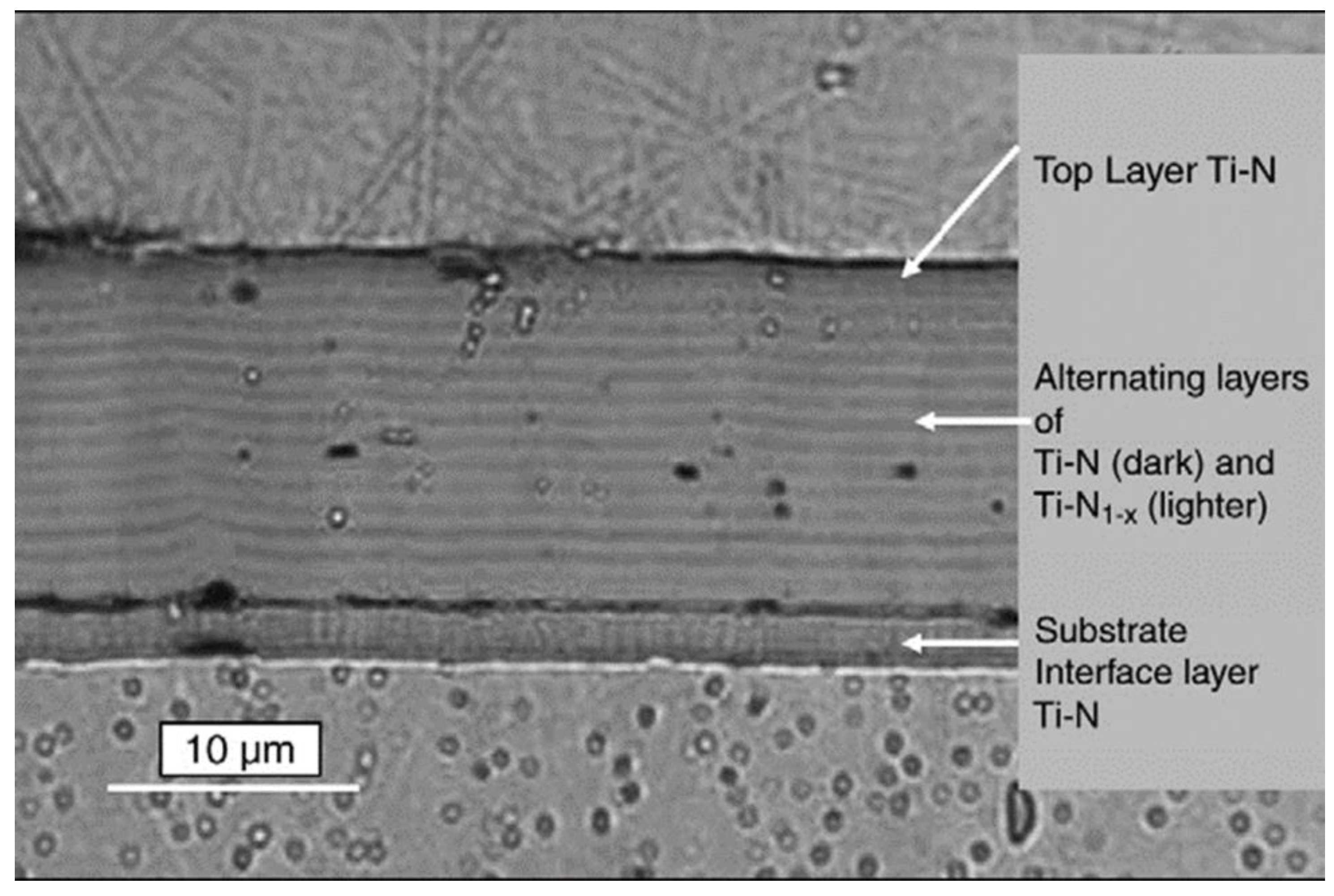
| 2 | TiN/TiN1−x (0.2/1 µm) multilayer coating | 15 to 25 µm | Cathodic arc | --- | 2 × 10⁻³ mm3/g @ 90°, 90 m/s, 50 μm alumina | [24] |
| 3 | Nanocomposite of nc-TiCN and a-SiCN having grain size of 5 nm to 7 nm | ~ 20 to 35 µm | Plasma enhanced magnetron sputtering | 20 to 40 GPa | ~1 × 10⁻³ mm3/g @ 90°, ASTM-G76-04, 50 μm alumina. (Erosion rate one order lower than the TiN coating) | [113,142,163] |
| 4 | Ti/TiAlN, Ni+Ti/TiN nanolayered multilayered coatings with two segments. Bi-layer thickness: 300 nm to 5 µm | ~ 10 to 60 µm | Filtered arc deposition | 20 to 80 GPa | Mass loss: 0.1 to 0.2 µg/g, 90°, 50 μm alumina. Test standard: GEET50TF121 | [165] |
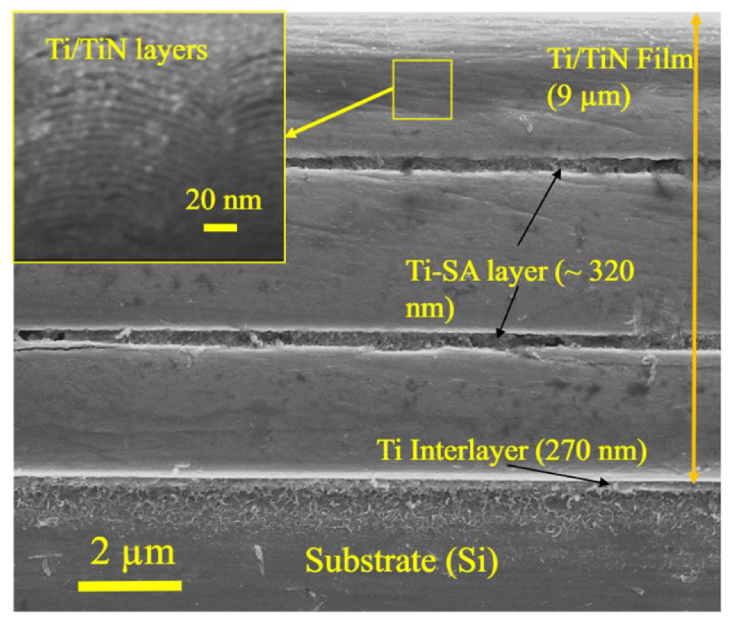
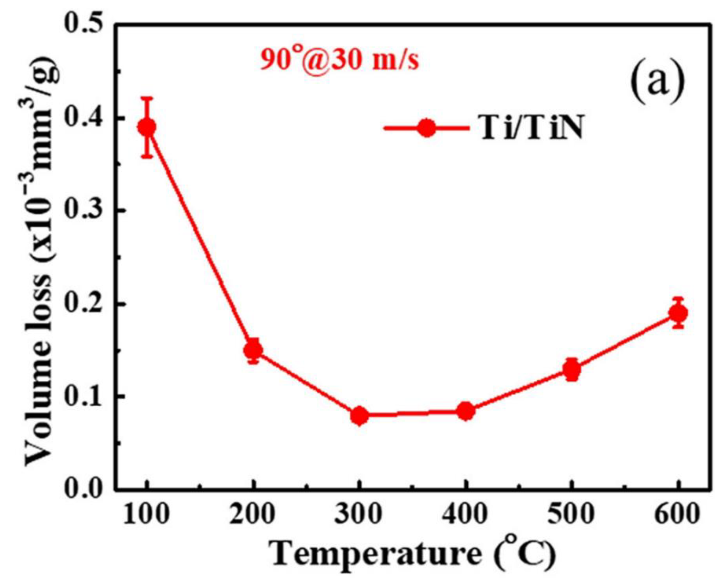
| 5 | Ti/TiN multilayer coating with stress absorbing metal layers. Bi-layer thickness~ 7.5 nm | ~ 9 µm | Unbalanced magnetron sputtering | ~ 17 GPa | ~ 5.2 × 10⁻³ mm3/g @ ASTM-G76-13, 90°, 100 m/s, Test temperature: 400 °C, 50 μm alumina | [132] |
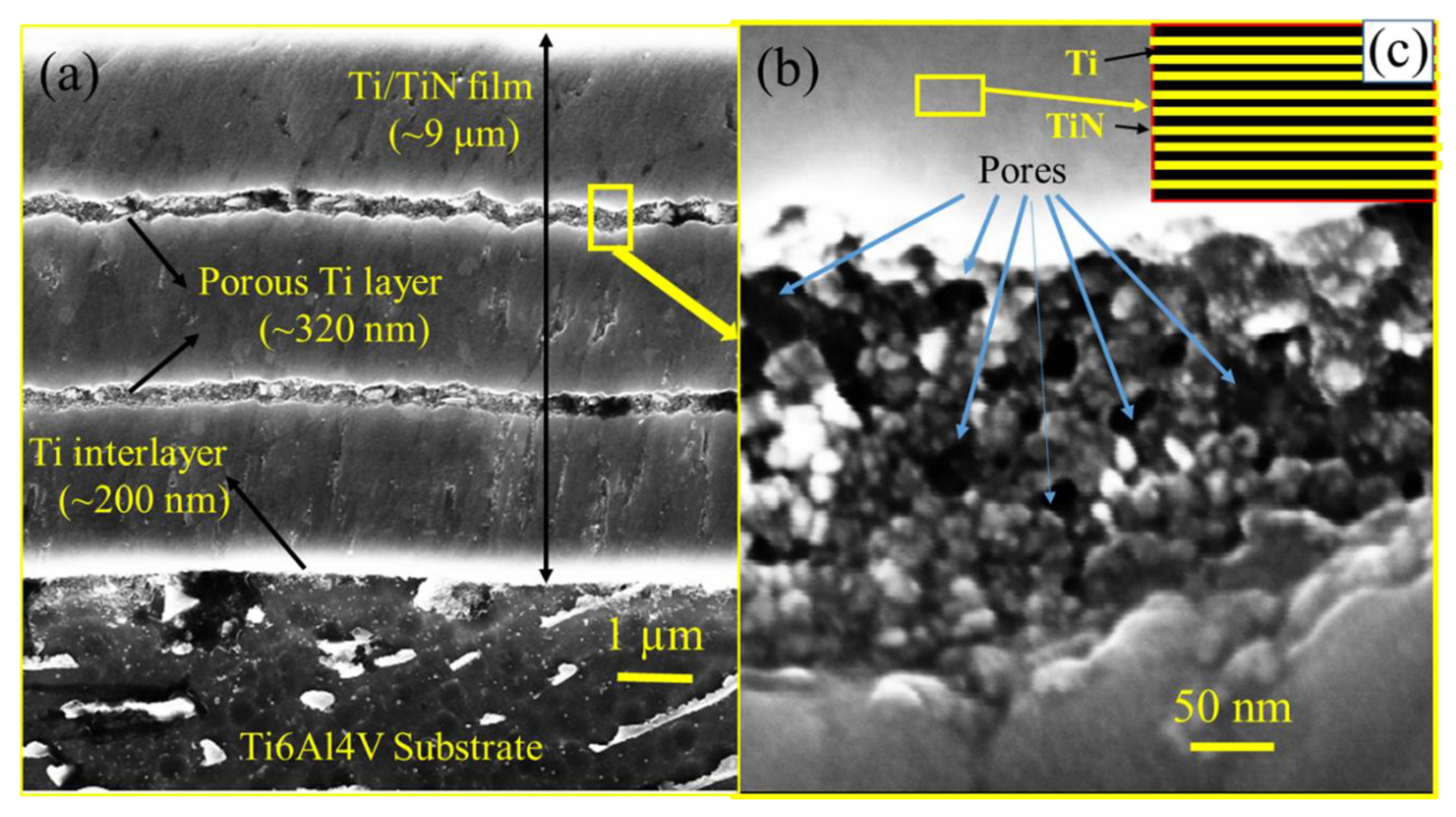
| 6 | Ti/TiN multilayer coating with energy-absorbing nano-porous metal layers. Bi-layer thickness~ 7.5 nm | ~ 9 µm | Unbalanced magnetron sputtering | ~ 18 GPa | ~ 2 × 10⁻³ mm3/g @ ASTM-G76-13, 90°, 100 m/s, Test temperature: 400 °C, 50 μm alumina | [153] |
| 7 | CrAlTiN, TiN, Single phase coating | ~ 16 µm | Arc physical vapor deposition | --- | Deposited blades were tested in a test rig with a sand erodent at ~151 m/s speed. CrAlTiN coating showed better erosion resistance compared to TiN | [120] |
| 8 | Ti/TiN/TiAlN multilayer coatings | ~10 µm | Cathodic arc system | --- | ~0.060 mg/g and 0.024 mg/g at the erosion angle of 90° and 30°, respectively | [166] |
| 9 | Ti0.52Cr0.48N (20 nm)/Ti0.40Cr0.60N (40 nm) multilayer coating | ~20 µm | Cathodic arc system | 28 GPa | ~217 g/cm2 @ 70 m/s, 90°, silica particles of 200 µm size, ASTM G76. | [167] |
Publisher’s Note: MDPI stays neutral with regard to jurisdictional claims in published maps and institutional affiliations. |
© 2022 by the authors. Licensee MDPI, Basel, Switzerland. This article is an open access article distributed under the terms and conditions of the Creative Commons Attribution (CC BY) license (https://creativecommons.org/licenses/by/4.0/).
Share and Cite
Bonu, V.; Barshilia, H.C. High-Temperature Solid Particle Erosion of Aerospace Components: Its Mitigation Using Advanced Nanostructured Coating Technologies. Coatings 2022, 12, 1979. https://doi.org/10.3390/coatings12121979
Bonu V, Barshilia HC. High-Temperature Solid Particle Erosion of Aerospace Components: Its Mitigation Using Advanced Nanostructured Coating Technologies. Coatings. 2022; 12(12):1979. https://doi.org/10.3390/coatings12121979
Chicago/Turabian StyleBonu, Venkataramana, and Harish C. Barshilia. 2022. "High-Temperature Solid Particle Erosion of Aerospace Components: Its Mitigation Using Advanced Nanostructured Coating Technologies" Coatings 12, no. 12: 1979. https://doi.org/10.3390/coatings12121979