Article

Influence of Post-Deposition Thermal Treatments on the Morpho-Structural, and Bonding Strength Characteristics of Lithium-Doped Biological-Derived Hydroxyapatite Coatings

1
National Institute for Lasers, Plasma and Radiation Physics, 077125 Magurele, Romania
2
National Institute of Materials Physics, 077125 Magurele, Romania
3
Institute of Physical Chemistry “Ilie Murgulescu”, Romanian Academy, 060021 Bucharest, Romania
4
Department of Bioengineering, Faculty of Engineering, Goztepe Campus, University of Marmara, Istanbul 34722, Turkey
5
Center for Nanotechnology & Biomaterials Research, Goztepe Campus, University of Marmara, Istanbul 34722, Turkey
*
Author to whom correspondence should be addressed.
Coatings 2022, 12(12), 1883; https://doi.org/10.3390/coatings12121883
Submission received: 4 November 2022 / Revised: 25 November 2022 / Accepted: 29 November 2022 / Published: 4 December 2022
(This article belongs to the Special Issue Synthetic and Biological-Derived Hydroxyapatite Implant Coatings)

Abstract

:
We report on hydroxyapatite (HA) of biological-origin doped with lithium carbonate (LiC) and lithium phosphate (LiP) coatings synthesized by Pulsed laser deposition onto Ti6Al4V substrates fabricated by the Additive manufacturing technique. A detailed comparison from the structural, morphological, chemical composition, wetting behavior and bonding strength standpoints of as-deposited (NTT) and post-deposition thermal-treated (TT) coatings at temperatures ranging from 400 to 700 °C (i.e., TT400–TT700), was performed. Structural investigations indicated a complete crystallization of the initially amorphous HA-based layers at temperatures in excess of 500 °C. The morphological analyses emphasized the rough appearance of the film surfaces, consisting of particulates whose dimensions increased at higher temperatures, with an emphasis on LiC coatings. AFM investigations evidenced rough surfaces, with a clear tendency to increase in corrugation with the applied temperature, in the case of LiC coatings. A hydrophobic behavior was observed for control, NTT and TT400 samples, whilst a radical shift towards hydrophilicity was demonstrated for both types of structures at higher temperatures. In the case of TT500–TT700 coatings, the pull-out adherence values increased considerably compared to control ones. Taking into consideration the obtained results, the positive influence of post-deposition thermal treatments (performed at higher temperatures) on the physical–chemical and mechanical properties of LiC and LiP coatings was indicated. Alongside these improved characteristics observed at elevated temperatures, the sustainable nature of the used BioHA materials should recommend them as viable alternatives to synthetic HA ones for bone implant applications.

Graphical Abstract

1. Introduction

Bone joint defects/diseases, along with edentation, represent difficult and frequent clinical problems with high incidence in the medical field and are mainly caused by age, trauma, infections, tumor resection or congenital/hereditary disorders [1]. One should note that the frequency of these medical problems is foreseen to expand even more as a result of the increase in life expectancy worldwide. A testimony for an increased demand for advanced bone implants stand in global market research studies. For instance, Allied Market Research projected that the global market of orthopaedic and dental implants will experience a steep growth in the following next years, reaching a value of $12,743 million USD by 2023 [2], and of $66,636 million USD by 2025 [3].
Nowadays, the materials of choice for orthopedic and dental implants are generally fabricated from titanium (Ti) and its medical-grade alloys (e.g., Ti6Al4V, Ti6Al7Nb) [4,5]. Ti6Al4V was shown to possess important characteristics, such as high strength and fracture toughness, superior corrosion resistance, low density, excellent biocompatibility, and favorable osseointegration characteristics [6,7]. One should note here that, in the case of senior patients, the osseointegration of such implants is difficult to achieve in a short period of time and that is why bone cements are preferred [8]. Unfortunately, such an implant has a limited life-time and, considering the increase in life expectancy mentioned above, it can become a major deficit in the case of substitution surgeries. Despite the fact that, Ti6Al4V is considered highly biocompatible, there are studies from the literature which reported on both inflammatory reactions occurring around the implantation site [9,10], and the release of various chemical elements from the implants (i.e., vanadium and aluminum ions [4,9]), which can accumulate in the organs, with hard-to-predict long-term effects. Therefore, to surpass these inconveniences and to optimize the interface between the human body (“host”) and the implants, a bioceramic material is usually deposited on the surface of the metallic substrate in the form of a thin film. The aim of this coating is both to accelerate the osseointegration rate, and to ensure the biomimetism of the implant, by enhancing its long-term functionality [11]. Moreover, the use of this coating as a buffer layer offers protection against the release of unwanted metallic ions from the implants. In the latter case, crystalline coatings, with reduced corrosion, are preferred. Nowadays, the “gold” standard material used to coat implants is hydroxyapatite (HA). HA is one of the most investigated calcium phosphates (CaPs) for osseointegrative applications due to its excellent biocompatibility, high biomineralization capacity, controlled degradation speed, and good osteoconductivity [12]. Synthetic HA is generally produced by chemical laborious protocols. Thus, one alternative, sustainable solution to produce natural HA is to extract it from abundant biological resources [13,14] (e.g., bones resulted from the food-processing industry). It was reported that animal bone-derived HA (further denoted as BHA), in comparison to synthetic HA, contains an array of trace-elements (e.g., Na, Mg, Sr, and K), with definite bio-functional roles [15], as well as an improved mechanical performance [16]. In addition, BHA demonstrated a high metabolic activity, a much more dynamic response to the environment [17], and less intense inflammatory reactions [18].
Pulsed laser deposition (PLD) was delineated as a promising technology for the synthesis of bioceramic layers [19,20,21], due to good control over film stoichiometry and thickness, as well as to its ability to yield rough and well-adhered films [22]. Post-deposition thermal treatments performed on the synthesized layers are also to be mentioned here. Their role is both to restore the stoichiometry and to improve the overall crystalline status of the fabricated coatings [23].
Nowadays, different solutions to further improve the mechanical and biological properties of the fabricated HA films are being investigated. One such strategy is doping with different concentrations of reagents [24], among which Lithium (Li) plays a key-role. Thus, Li is a metal with important therapeutic properties, which range from the treatment of bipolar disorders to antibacterial, anticancer, antiviral, and pro-regenerative effects [25,26]. Its mechanism of action was shown to be extremely complex [25,27]. It was also reported that, when Li is substituted into the HA structure, it plays a double role: (i) it could induce a decrease in the solubility of HA [28,29], without interfering on biocompatibility [30], and (ii) an enhancement of mechanical properties, without altering the HA structure [23].
In this respect, our previous PLD studies suggested that the Li addition to BHA can further improve the adhesion and differentiation of human mesenchymal stem cells to osteoblasts lineage, as compared to the undoped BHA coatings [31,32]. In the framework of the current study, we therefore aimed to survey if a fine tuning of the physical–chemical and surface energy characteristics (with direct consequences on the bio-functional response), as well as of the bonding strength of Li-doped BHA coatings could be further made possible via post-deposition annealing treatments performed at different temperatures (in the range of 400–700 °C) and ambient (i.e., air and water-vapors enriched atmosphere). To the best of our knowledge, this is the first report on the influence of post-deposition thermal treatments on the structural, morphological, compositional, wetting behavior and bonding strength characteristics of bone-derived HA coatings synthesized by the PLD technique.

2. Materials and Methods

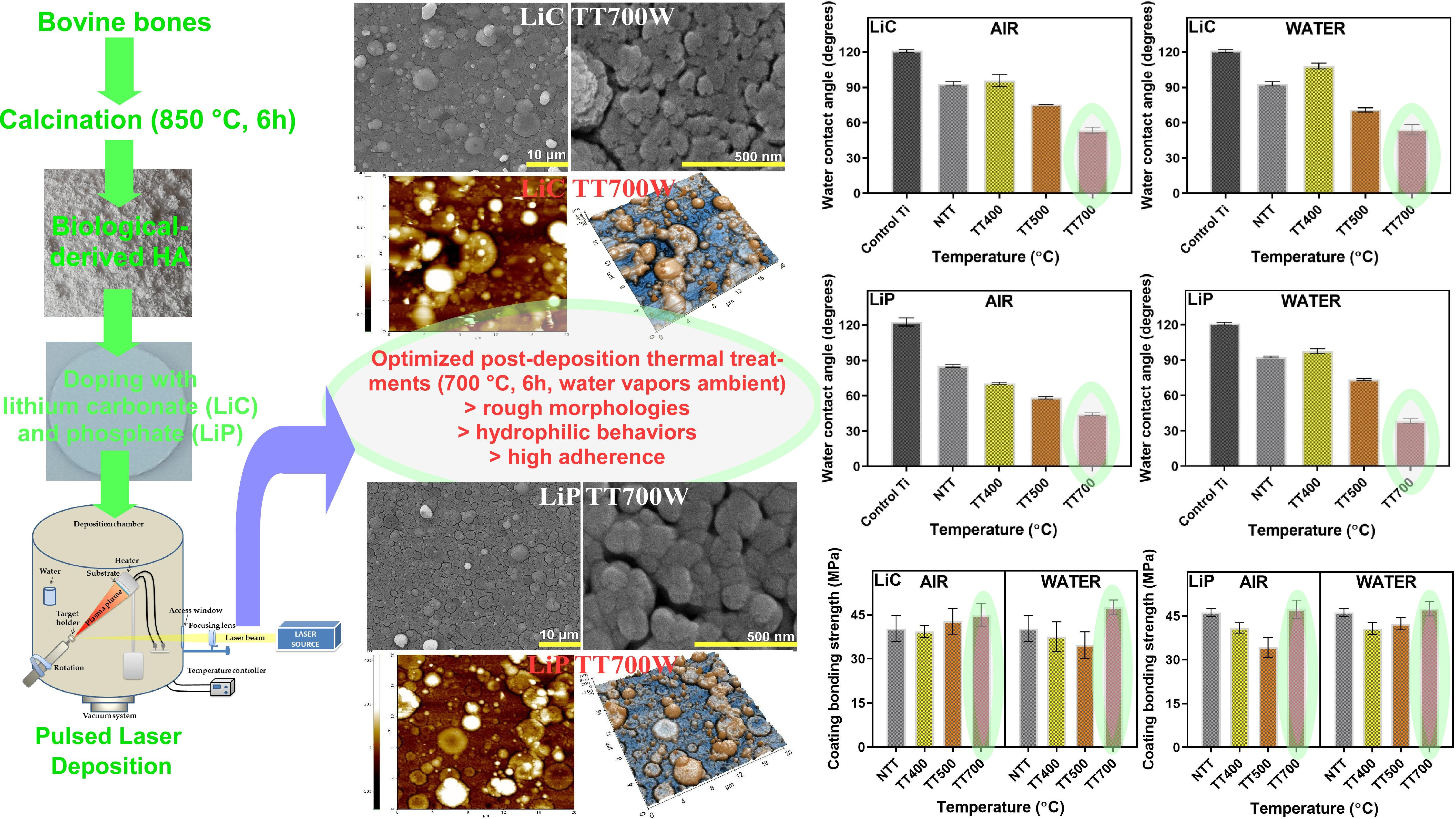
2.1. Powder Preparation

The BHA powders were obtained from bovine femoral bones, which were subjected to a veterinary control before usage. The extremities of bones were cut off and only the femoral shafts were further used. The bone marrow along with all the other soft tissue residues were removed from the bones. The femoral shafts were cut into small pieces and washed thoroughly using distilled water. They were then introduced for two weeks into an alkaline sodium hypochlorite solution (1%), for deproteinization. After washing and drying, all the bone pieces were calcined at 850 °C for 4 h in air (using an electric laboratory oven, Protherm model, Alserteknik Inc., Istanbul, Turkey), for the complete elimination of all organic bone components. The as-obtained bone pieces were first crushed by grinding and then introduced into a ball mill to obtain fine powders, with particles of submicronic dimensions. Next, all powders were calcined again at 850 °C for 4 h in air, with a heating rate of 4 °C/min. The combined chemical inactivation treatment and thermal processing at a high temperature eliminates all risks of disease transmission [33].
The BHA powders were prepared in accordance with the EU settlement No. 722/2012 and ISO No. 22442-1:2015, which regulate the management of health security issues when working with products derived from tissues of animal origin.
Li (1 wt.%) was incorporated into BHA by using two source powders: Li2CO3 and Li3PO4 (Sigma Aldrich, St. Louis, MI, USA). Batches of Li-BHA of ~40 g were prepared by powder mechanical mixing using a high energy Retsch S 100 ball mill (200 rot/min, for ~15 min). To avoid any possible mixing with reused powders, virgin powders were always used.

2.2. Target Preparation

Amounts of 3 g of Li2CO3/BHA (further denoted as LiC) and Li3PO4/BHA (further denoted as LiP) powder mixtures were introduced into a stainless-steel mold (Specac Ltd., Orpington, UK), with a diameter of 2 cm. The LiC and LiP mixes were next compacted by pressing at ~6 MPa. Pellets with a thickness of ~0.5 cm were thus obtained. Further, the powder pellets were sintered into well-hardened, crack-free, PLD targets at 700 °C/4 h (heating rate 5 °C/min, natural cooling down). One should note here that sintering at temperatures higher than 700 °C was not possible owing to the low decomposition temperatures of Li2CO3.

2.3. Substrates Preparation

The Ti6Al4V substrates were fabricated by additive manufacturing, starting from a micro-sized powder (LPW Technology, Widness, UK), and using the experimental assembly presented in Ref. [34]. For the powder delivery, an automated powder feeder (Trumpf, Ditzingen, Germany) was used, connected through hoses (6 mm in diameter) to a nozzle with three flow channels, mounted on a robotic system TruLaser Robot 5020 (Trumph, Ditzingen, Germany), made of a Kr30HA robot (Kuka Robotics, Angsburg, Germany) with six movement axes. The translation speed was set at 1 m/min. The powder was transported to the robot using a He–Ar mixture (1:3 ratio) gas, with a flow rate of 3 g/min. The Gaussian laser beam used to melt the powder had a selected peak power of 1 kW and a diameter of the surface focused spot size of 600 µm. The beam was supplied through an optical fiber and generated by a Yb:YAG source (λ = 1030 nm, continuous wave), model TruDisk 3001 (Trumpf, Ditzingen, Germany). The technical drawing of the Ti implant substrates was designed in the graphical engineering software SolidWorks® (Dassault Systems, Vélizy-Villacoublay, France) and imported in TruTops Cell® (Trumpf, Ditzingen, Germany), which is a movement code generator for the robotic arm. Using these optimized parameters, a bulk shape was printed and further sliced using a disk cutting machine, model Brillant 200 (ATM, Mammelzen, Germany). Individual Ti6Al4V substrates, with thicknesses of ~3 mm, were therefore obtained.

2.4. PLD Coatings

All PLD experiments were performed inside a stainless-steel deposition chamber, using a pulsed UV KrF* COMPexPro 205F excimer laser source (λ = 248 nm, τFWHM ≤ 25 ns) (Coherent, Santa Clara, CA, USA), operated at a frequency repetition rate of 10 Hz.
The ablated material was transferred and collected both onto Ti6Al4V substrates (0.6 × 0.6) cm2 and double-side polished Si (100) wafers of (1 × 1) cm2 (Medapteh Plus Cert SRL, Magurele, Romania). They were placed parallel to the target surface, at a separation distance of 5 cm. Prior to introduction inside the deposition chamber, all substrates were cleaned in an ultrasonic bath Elmasonic X-tra 30H (Elma Schmidbauer GmbH, Singen, Germany), according to a protocol described in Ref. [32]. The Si wafers (which are easy to cleave) were used both for the cross-sectional scanning electron microscopy (SEM) analyses to infer the PLD films thickness, and AFM investigations. To ensure the best possible adherence of the coatings [35], the Ti and Si substrates were plasma cleaned using a Diener system (Diener Electronic, Ebhausen, Germany), prior to the introduction into the reaction chamber.
The laser beam was incident at 45° onto the target′s surface and the fluence was set at 4 J/cm2, with a corresponding laser energy of 360 mJ. During deposition, all substrates were heated and maintained at a constant temperature of 500 °C, by a PID-Excel temperature controller (Excel Instruments, Mumbai, India). The heating and cooling ramps were 20 and 10 °C/min, respectively. To avoid piercing and possible modification of the surface morphology induced by the laser radiation, the targets were continuously rotated during the multi-pulse deposition process with a frequency of 0.83 Hz (50 rot/min). For the deposition of one coating, 15,000 consecutive laser pulses were applied. All depositions were performed in water vapor-enriched ambient, at a residual pressure of 3.75 × 10⁻¹ Torr (~50 Pa).

2.5. Post-Deposition Thermal Treatments

The post-deposition thermal processing of implant-type coatings could be of particularly great importance for the engineering of their physical–chemical (e.g., crystalline quality, morphology, stoichiometry, surface energy) and mechanical properties. Consequently, in the framework of this study, the as-deposited PLD coatings were subjected to post-deposition thermal treatments at different temperatures (i.e., 400, 500 and 700 °C, respectively), in both air and water-vapor ambient, for 6 h (further denoted as TT400A–TT700A and TT400W–TT700W, respectively). For comparison reasons, batches of samples not subjected to thermal treatments (further denoted as NTT) were also used.

2.6. Physical-Chemical and Mechanical Characterization Methods

(a).
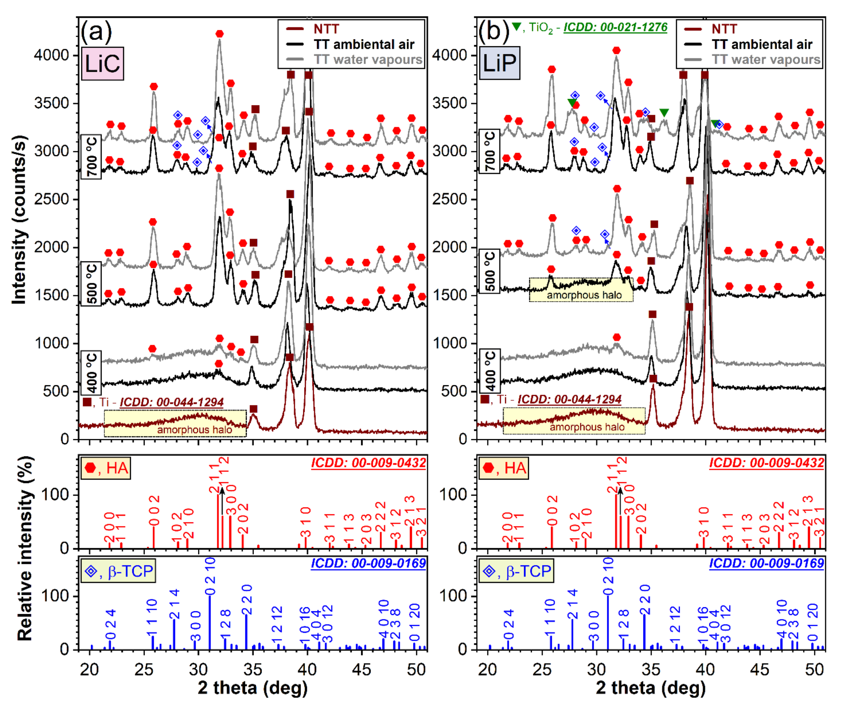
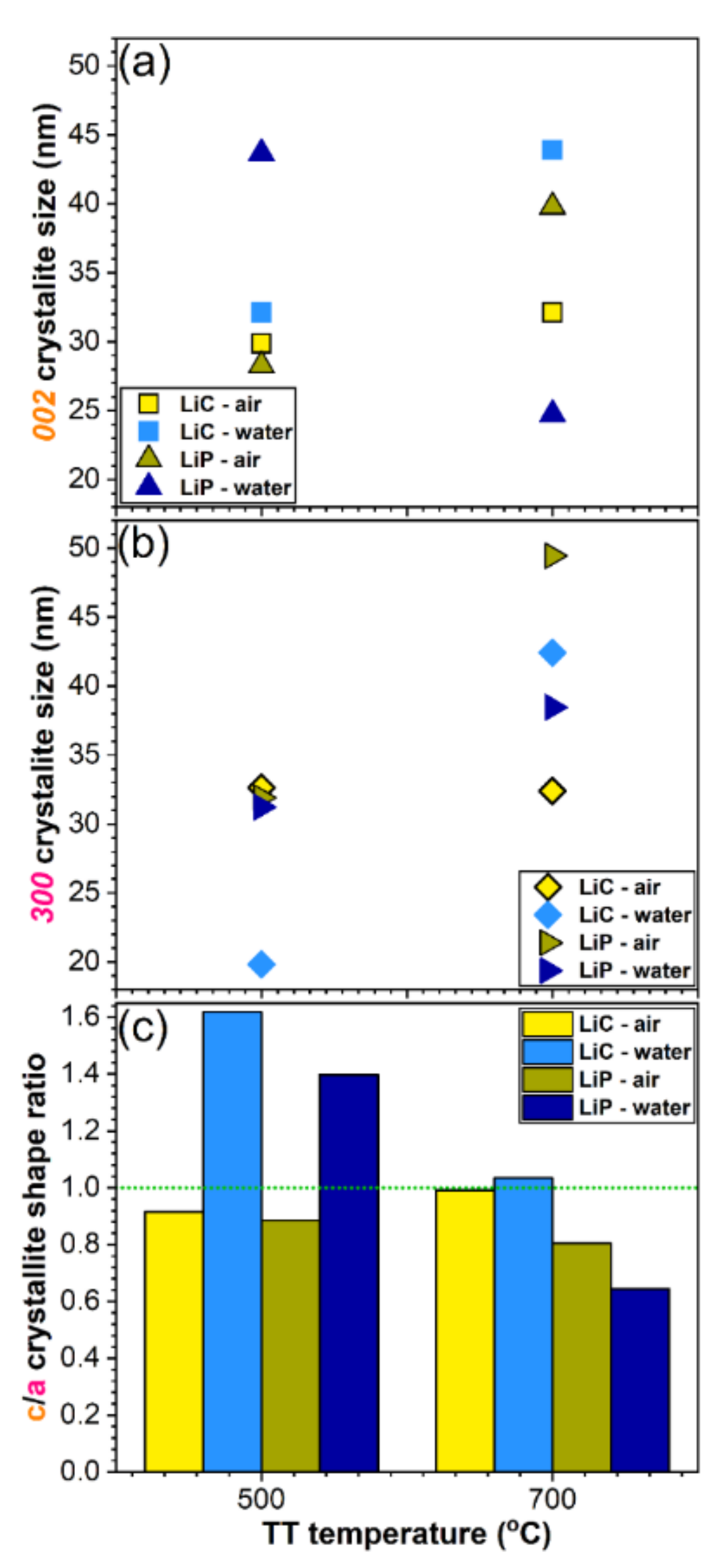
The crystalline status and phase composition of LiC and LiP coatings were investigated by X-ray diffraction (XRD), in grazing incidence (GI) geometry, using a Rigaku SmartLab (3 kW) equipment, with parallel beam setting and CuKα radiation (λ = 1.5406 Å). The angle of incidence (α) was 2°. The patterns were recorded in the 2θ = (10–60)° range, at an acquisition time of 1°/min.
(b).
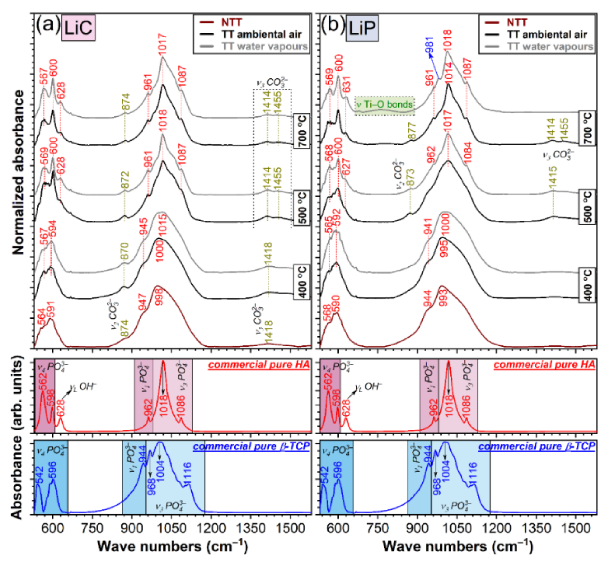
The chemical structure of LiC and LiP coatings was investigated by Fourier transform infrared (FT-IR) spectroscopy, using a Perkin Elmer BX Spectrum equipment, operated in an attenuated total reflectance (ATR) mode. A Pike-MIRacle diamond head (0.18 cm diameter) was used. All measurements were performed on Ti substrates, in the range (1600–500) cm−1, with a resolution of 4 cm−1 and a total number of 64 scans/experiment.
(c).
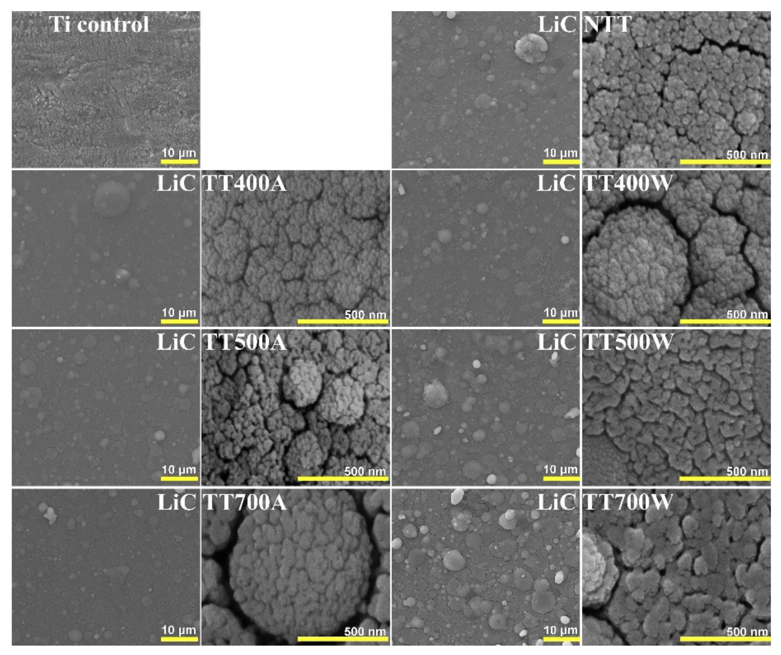
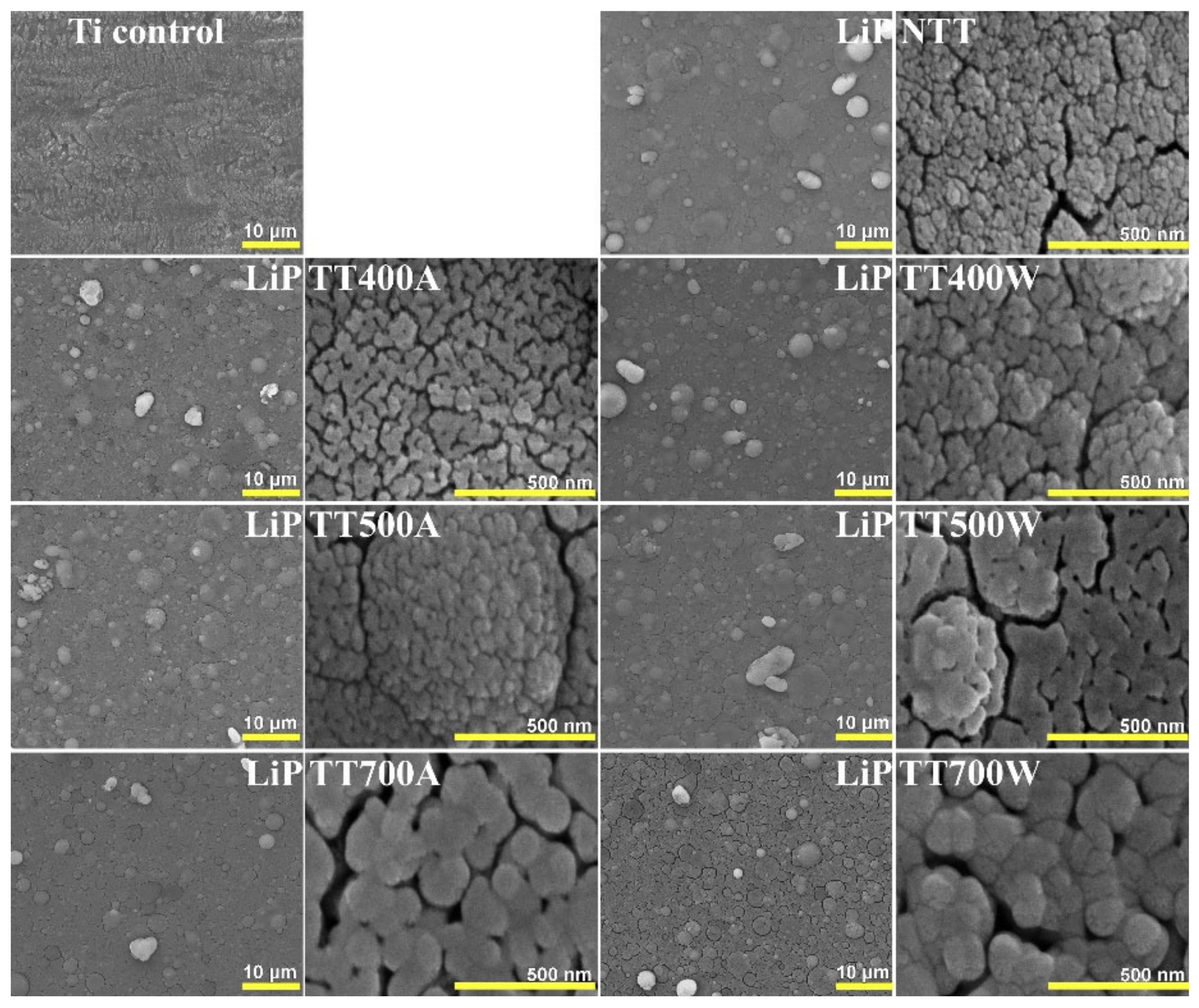
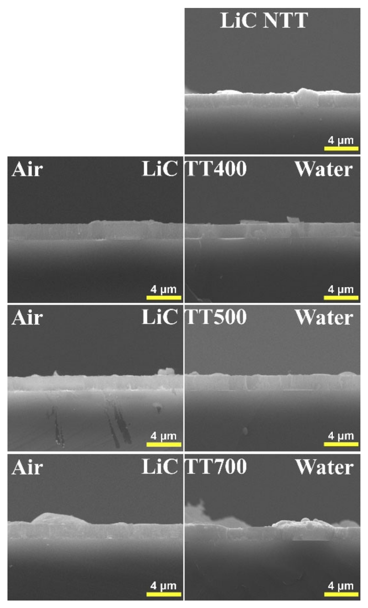
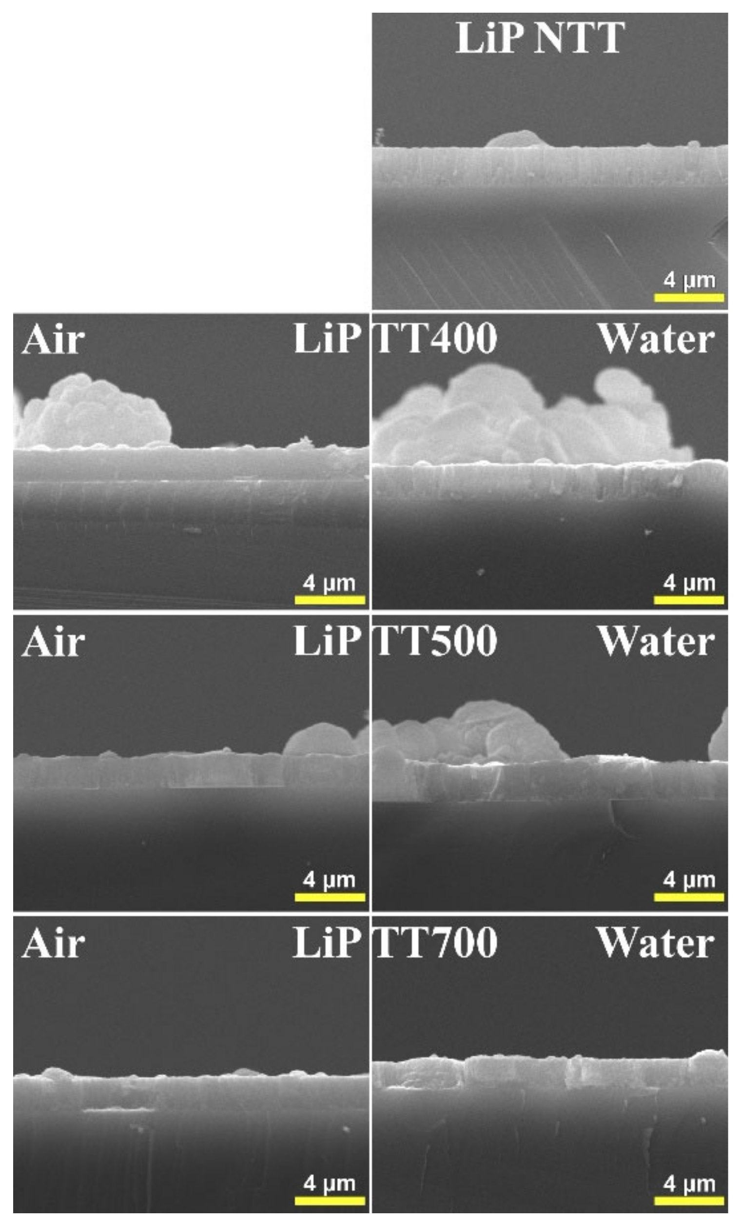
The surface and bottom-to-top morphologies of LiC and LiP coatings were investigated using SEM, in top- and cross-view modes, respectively. An FEI Inspect S50 electron microscope (Field Electron and Ion Company, Hillsboro, OR, USA), used in the secondary electron mode, at an acceleration voltage of 20 kV, was used. Before examination, to prevent electrical charging, all samples were coated with a thin layer (10–12) nm of Au.
(d).
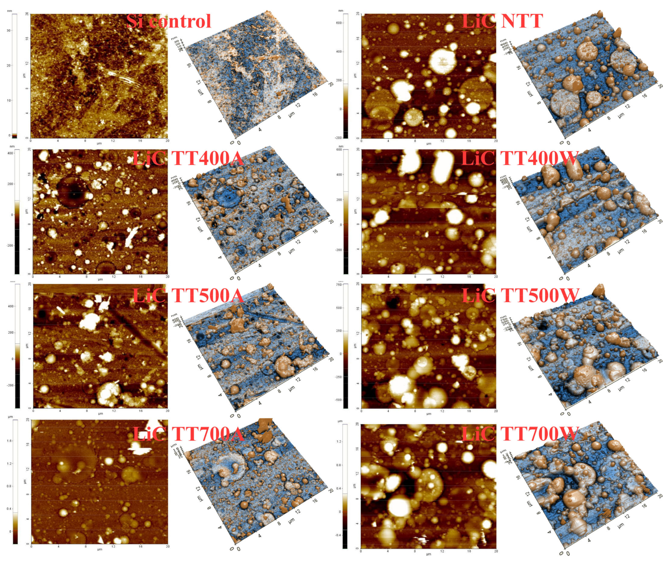
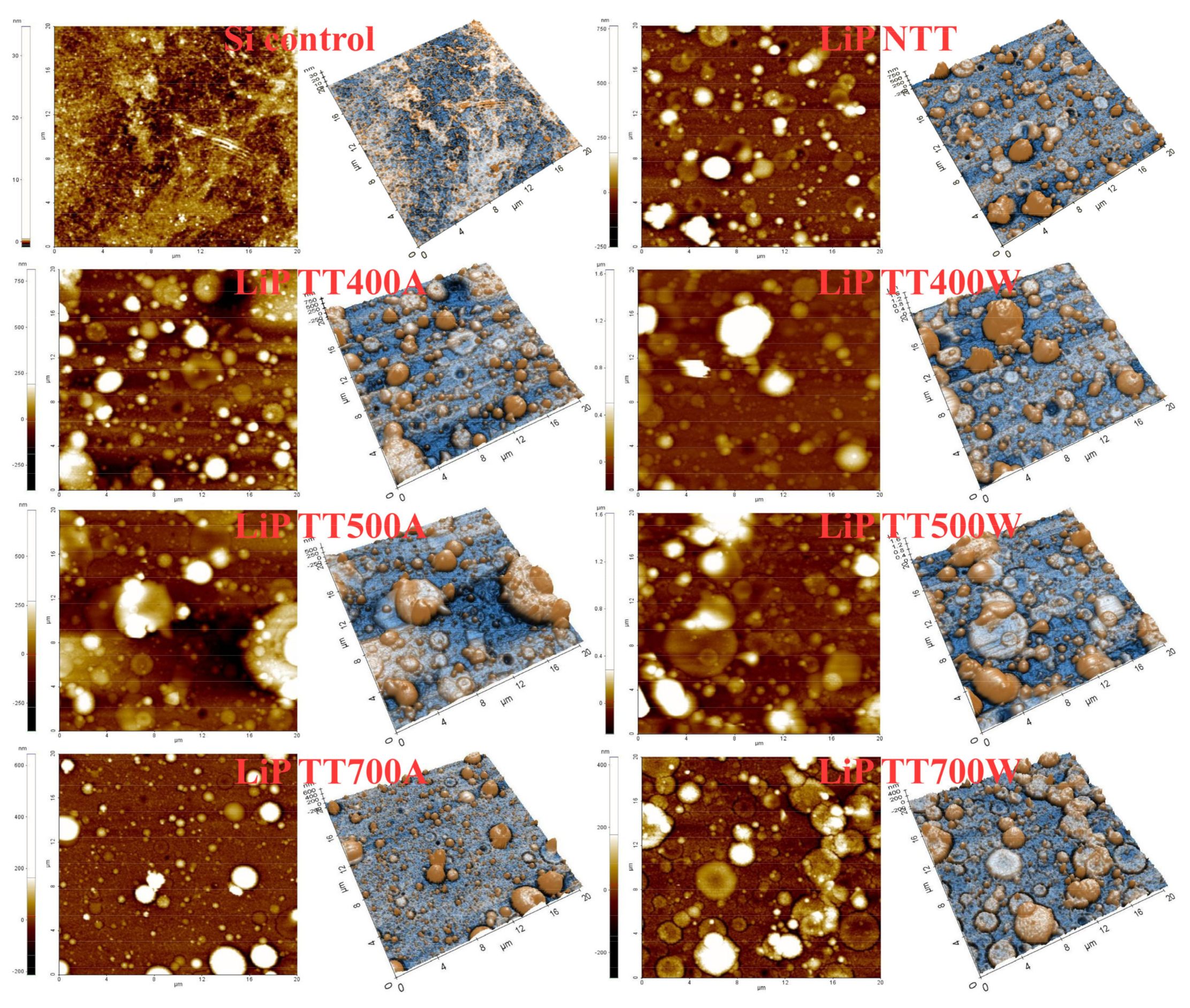
To better emphasize the topological surface peculiarities of LiC and LiP coatings, high resolution Atomic Force Microscopy (AFM), performed in non-contact mode on a XE-100 apparatus from Park Systems, was used. Sharp tips (PPP-NCHR type from NanosensorsTM, Neuchâtel, Switzerland), having a length of 125 µm, a 30 µm width and a radius of curvature of less than 8 nm, were used for surface scanning over areas of (20 × 20) µm2. All AFM measurements were performed at room temperature (RT). The textural (amplitude) parameters, namely average roughness (Rq), surface skewness (Rsk) and surface kurtosis (Rku), were determined.
(e).
The chemical composition of LiC and LiP samples was assessed by energy dispersive X-ray spectroscopy (EDS). For these measurements, a SiLi EDAX Inc. detector (Mahwah, NJ, USA), operated at 20 kV, was used. The elemental analyses were performed in triplicate, on different areas ((250 × 250) µm2) of the deposited layers.
(f).
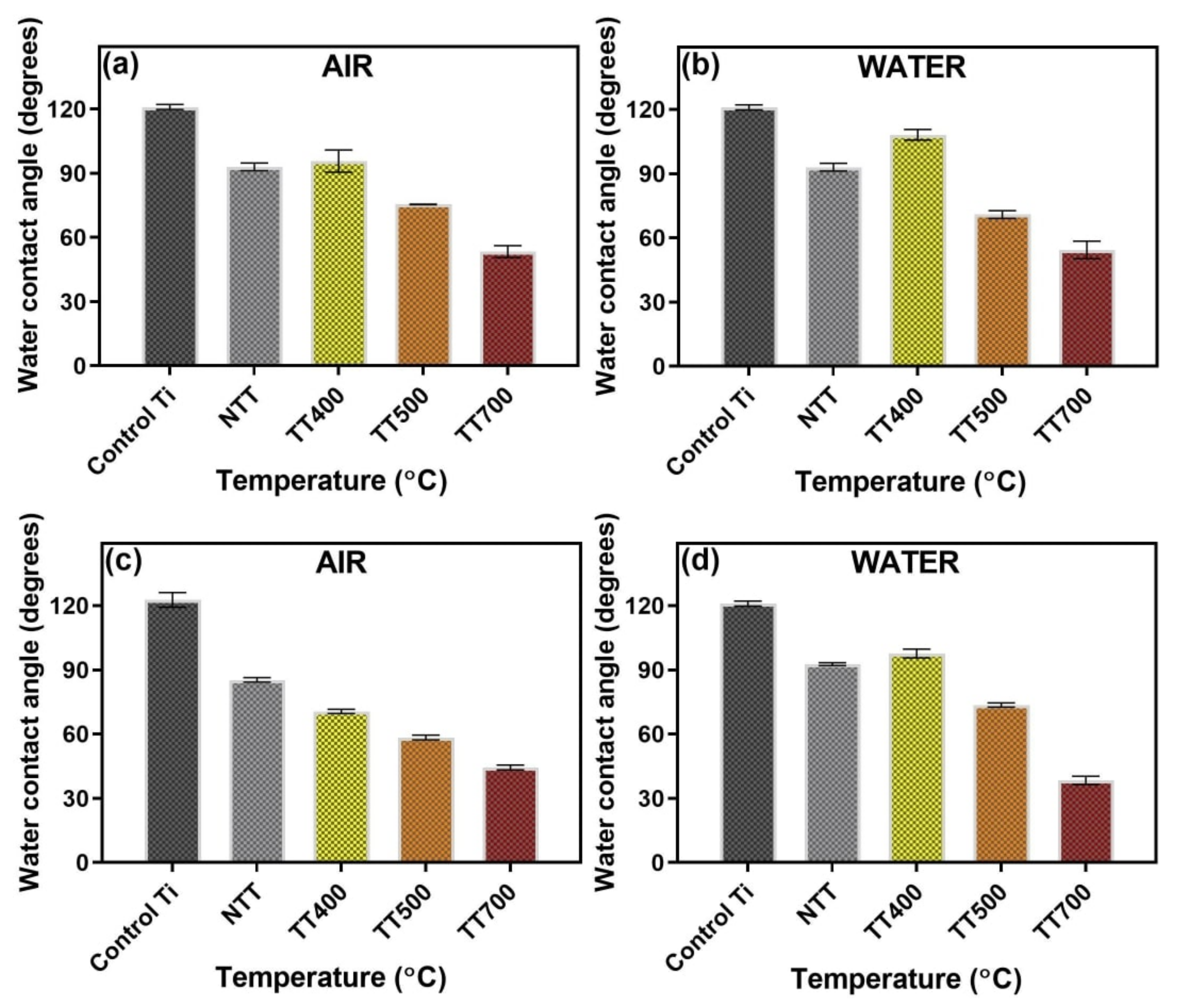
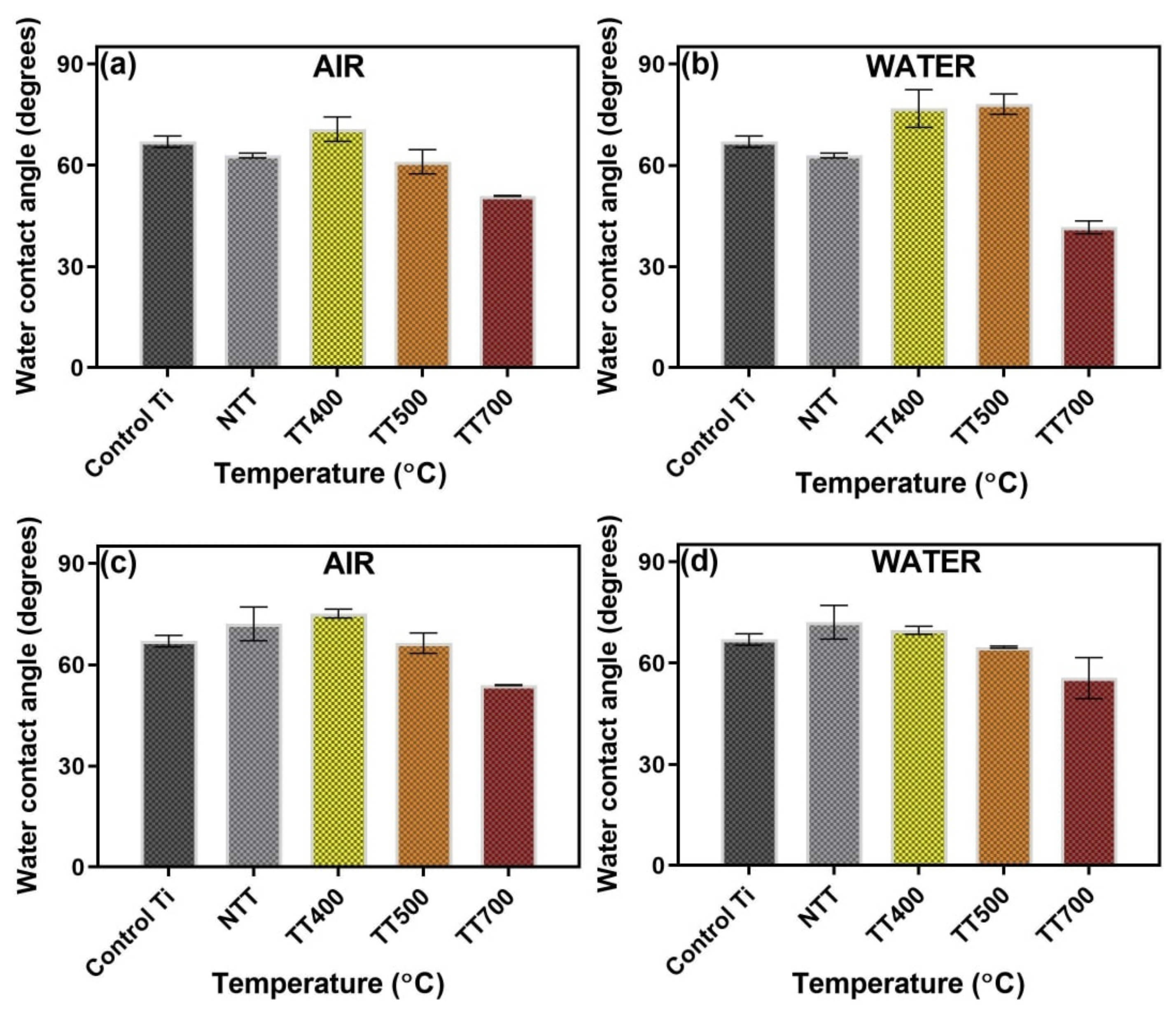
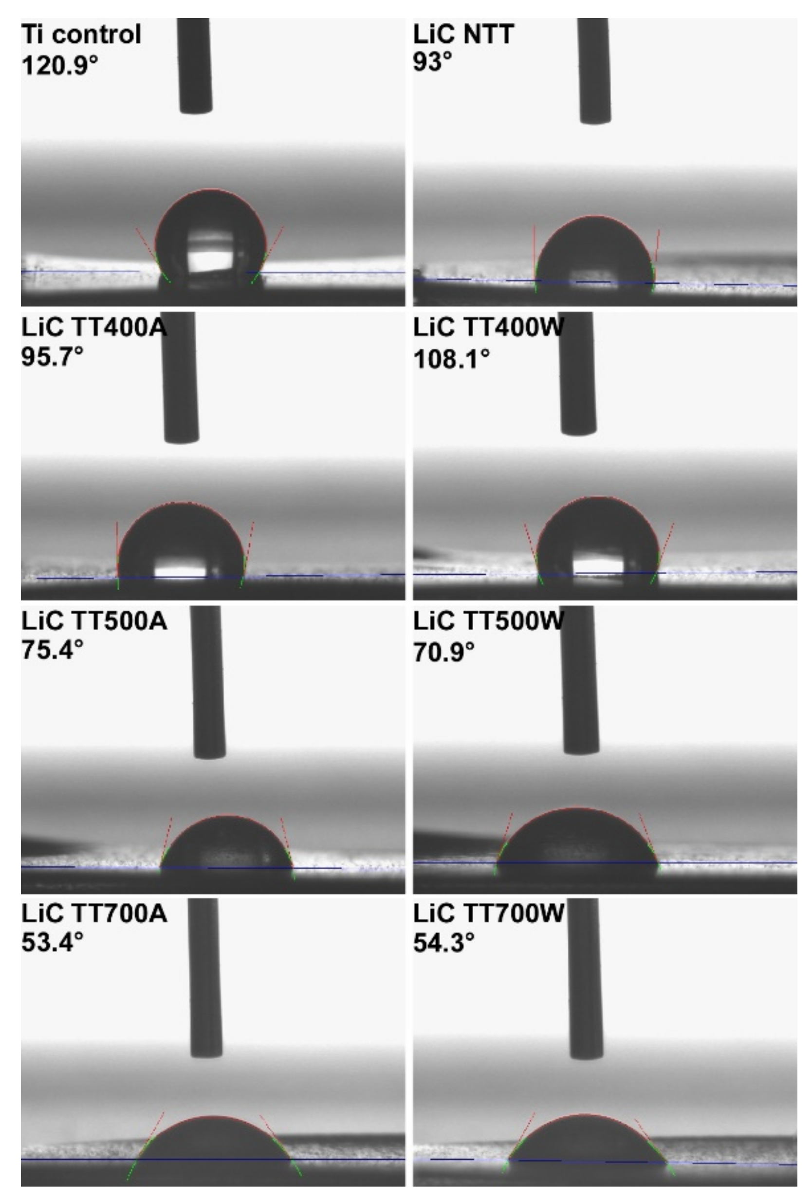
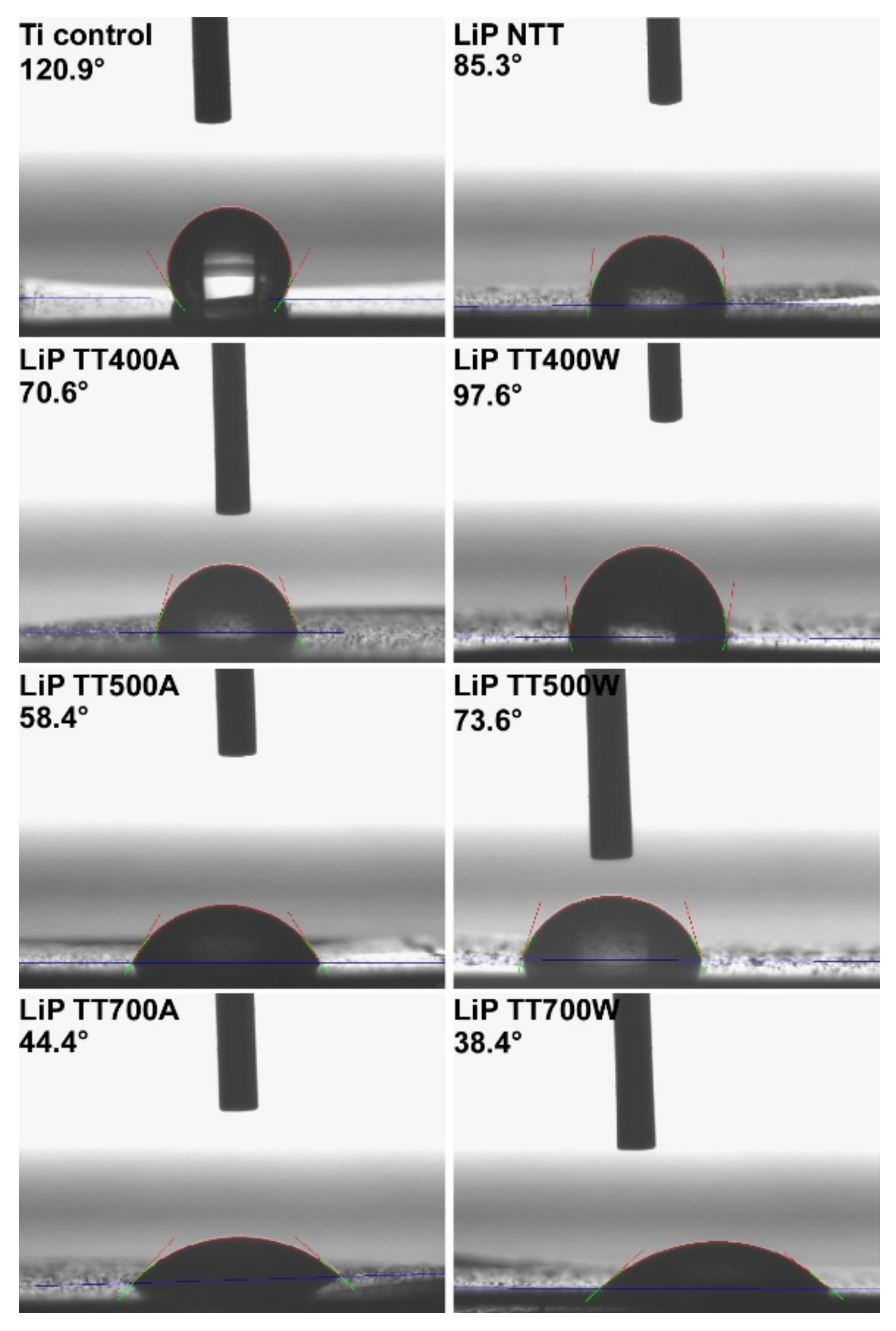
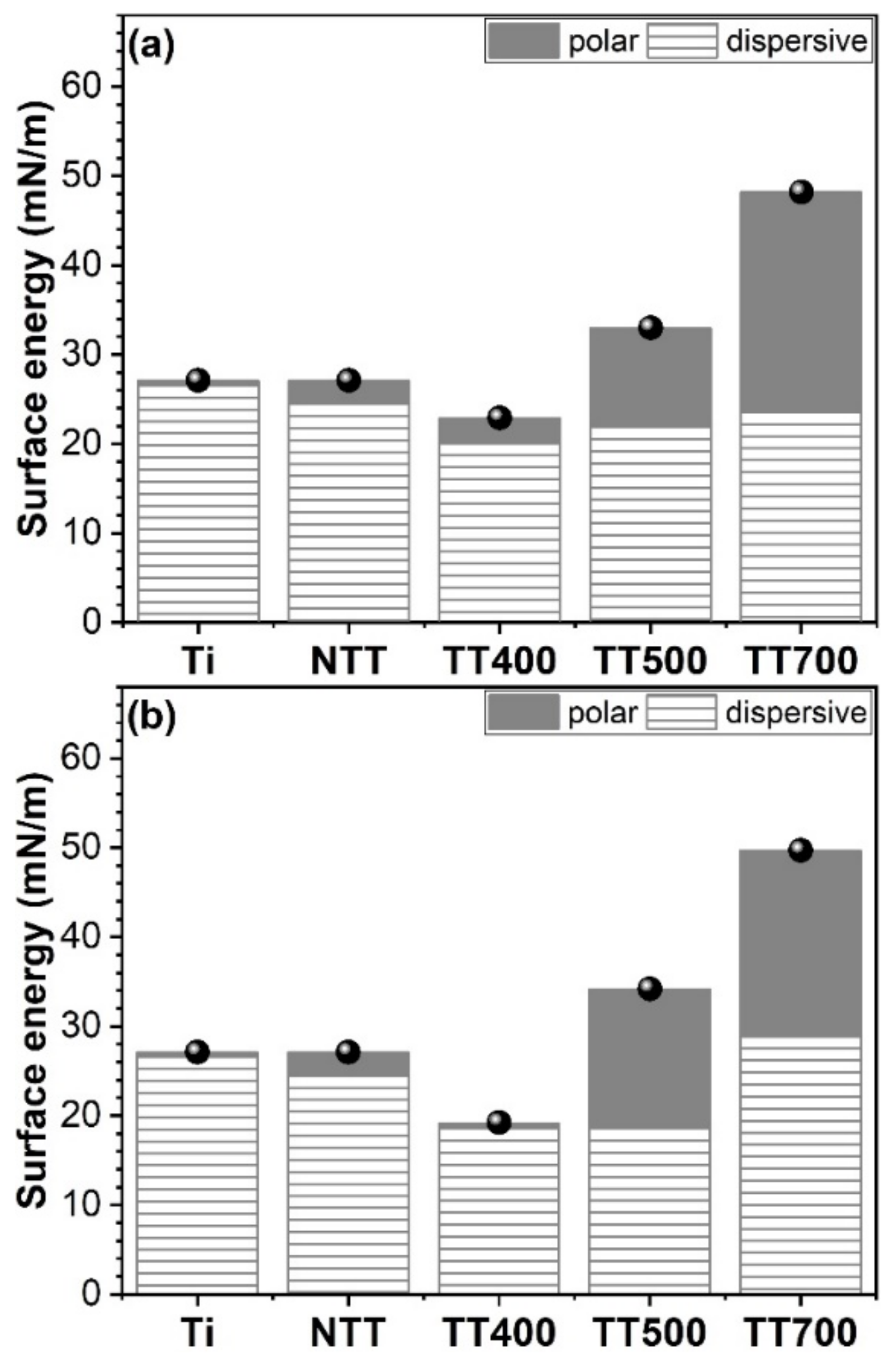
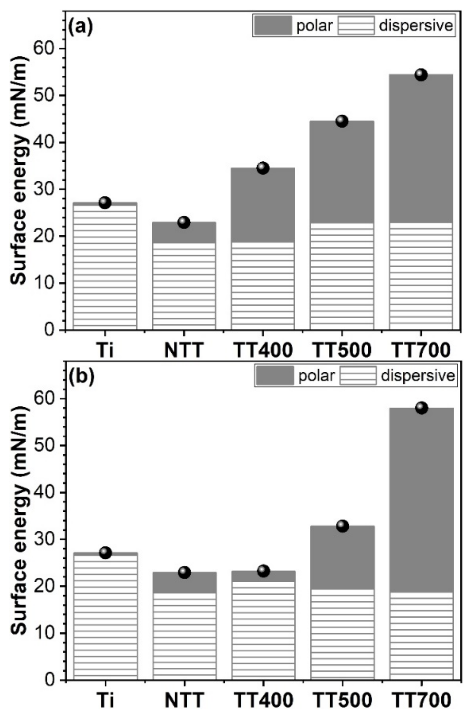
The wetting properties of the LiC and LiP coatings were investigated by static (equilibrium) contact angle (CA) measurements, using a Drop Shape Analysis System, model DSA100 (Krüss GmbH, Hamburg, Germany). The samples were positioned on a flat platform, under the tip of a blunt-end, stainless steel needle, with an outer diameter of 0.5 mm. The needle was attached to a syringe pump controlled by the DSA3® PC software and used for dripping liquids with a controlled volume on the test surface and for the CA evaluation. The volume of one liquid droplet was of ~1 μL. For each sample, the measurements were performed on two different regions of the surface. The CA measurements were performed by fitting the experimental profile of the sessile drop with a second-degree polynomial or with the equation of the circle, after which the slope of the tangent to the drop at the point of intersection with the line separating the liquid–solid–vapor interface was calculated. The video camera was tilted at an angle of ~2° to the sample plane. All measurements were performed at RT, in duplicate (on two identical samples). Based on the measured CA values, the solid Surface Free Energy (SFE) was determined. For the CA and SFE measurements, two standard liquids (water and diiodomethane) were used, for which one knows: the surface tension (γwater = 72.8 mN/m; γdiiodmethane = 50.8 mN/m), and the dispersion and polar components (γwaterd = 21.8 mN/m, γwaterp = 51 mN/m, and γdiiodmethaned = 48.5 mN/m, γdiiodmethanep = 2.3 mN/m). Using the CA values obtained for the two testing liquids, both the polar and dispersion parts of the synthesized coatings, and the total SFE, was estimated by applying the Owens–Wendt method [36].
(g).
The adherence of the LiC and LiP coatings to the Ti substrate was estimated by the pull-out method. A standardized instrument, PAThandy AT101 (maximum pulling force = 1 kN) from DFD Instruments® (Kristiansand, Norway), equipped with stainless steel test elements with a diameter of Φ = 0.28 cm, was used. The complete procedure was detailed elsewhere [37], and it complies with the ASTM D4541 and ISO 4624 standards. The measurements were performed on quadruplicates.

3. Results and Discussion

3.1. X-ray Diffraction

The GIXRD patterns of the LiC- and LiP-based PLD coatings, thermally processed under different conditions (air and water vapor ambient), are comparatively presented in Figure 1a,b. As expected, due to the low thickness of the deposited layers, the diffractograms were dominated by the high intensity peaks (i.e., 1 0 0, 0 0 2, and 1 0 1) of the Ti substrate (ICDD: 00-044-1294). While initially amorphous (i.e., NTT—as-deposited)—as indicated by the shallow amorphous halo situated in the angular region 2θ ≈ (23–33)°—the films became progressively more crystalline with the increase of the post-deposition temperature. Consequently, the diffraction maxima of HA (ICDD: 00-009-0432), as the sole or dominant phase of the PLD films, became incrementally more salient.
The LiP coatings heat-treated in air (Figure 1b) elicited a latency of crystallization with respect to the LiC ones (Figure 1a). This was suggested by the persistence of the amorphous halo (while reduced in intensity, and accompanied by defined peaks of nano-crystalline HA) up to a temperature of 500 °C. More advanced structuring processes (i.e., HA crystallization followed by its decomposition) were generally noticed for the films annealed in water-vapor ambient. The formation of the β-TCP phase (ICDD: 00-009-0169) was hinted by (i) the left-hand side asymmetry of the 2 1 1 peak of HA, followed the advent of a definite shoulder appertaining to the maximum intensity 0 2 10 peak of β-TCP, and (ii) the increase in intensity of the 1 0 2 peak of HA, as consequence of the superimposition in the same angular region of the prominent 2 1 4 maximum of β-TCP. If in the case of LiC samples (Figure 1a), the partial decomposition of HA was disclosed only after the TT performed at 700 °C in both air and water-vapor ambient, in the case of LiP samples, the first signs of HA decomposition were evidenced at a lower temperature (i.e., TT performed at 500 °C in water-vapor ambient). Furthermore, while after the TT at 700 °C in air, the HA → β-TCP transformation of the LiP coatings was still marginal, in the case of the ones heat-treated in water-vapor ambient, the weight of the β-TCP was visibly increased (Figure 1b). This was supported by both the increase of the 0 2 10 β-TCP/2 1 1 HA peaks ratio, and the supplemental easier discrimination of diffraction maxima related to the 2 1 4 and 2 2 0 lines of β-TCP. Interestingly, in the case of LiP coatings annealed at 700 °C in water-vapor ambient, the additional presence of a well-defined TiO2-rutile phase (ICDD: 00-021-1276) was revealed. This is not unprecedented, since the formation of rutile was previously reported in the case of magnetron-sputtered HA films subjected to post-deposition heat-treatments at 750 °C [38]. It is most likely a consequence of the Ti substrate oxidation at the interface with the deposited film during the re-structuring and decomposition stages of HA (with oxygen diffusing from the film to the substrate surface).
The progressive incorporation of hydroxyl and carbonate functional groups into the HA lattice is known as a driving force for its crystallization [39,40]. Conversely, the gradual de-hydroxylation and de-carbonation of HA at higher temperatures, represents the starting point of HA restructuring, since its crystalline lattice will become faulty and unstable, and thus, susceptible to chemical reactions and decomposition [41,42].
The stronger HA → β-TCP decomposition, signaled in the case of LiP coatings annealed in water-vapor ambient at 700 °C, could be linked to a decrease in the heat-treatment efficacy (with the water vapors being more readily evaporated from the HA-based film surface at this high temperature). Furthermore, the excess of orthophosphate groups supplied by the Li source material (i.e., Li3PO4) used in the case of LiP samples, could act as a supplemental chemical destabilizer and decomposition adjuvant.
The crystallite size (crystalline coherence length) along the a- and c-axis of HA, was determined from the integral breaths of the 0 0 2 and 3 0 0 diffraction maxima by applying the Scherrer equation [43], after the subtraction of the instrumental breadth (using a NIST 1976b corundum standard reference material). The estimated a- and c-axis crystallite size values are plotted comparatively in Figure 2a,b.
The c/a crystallite shape anisotropy factors are presented in Figure 2c. As anticipated, the (a- and c-axis, respectively) crystallite sizes experienced a moderate (i.e., LiC in air) or markedly increase (i.e., LiP in air, LiC in water-vapor ambient) with the heat-treatment temperature, with a single exception: LiP coatings annealed in water-vapor ambient at 700 °C. In this particular case, a strong diminution of the crystalline coherence length along the c-axis was recorded. This should be considered a direct consequence of the more prominent structural changes experienced by this type of coating (namely, increase of β-TCP share, and emergence of the rutile phase at the film–substrate interface). Interestingly, the c/a shape factors (Figure 2c) indicated that both LiC and LiP samples heat-treated in air were quasi-isotropic (ratios close to unity) irrespective of temperature, whilst the ones annealed in water-vapor ambient at 500 °C were markedly oblong. When the heat-treatment temperature is increased (to 700 °C) for the latter samples, their crystallite shape became either isotropic (for LiC) or flattened (for LiP).

3.2. Fourier Transformed Infra-Red Spectroscopy

The FTIR-ATR spectra of the NTT and TT LiC and LiP coatings are presented comparatively in Figure 3a,b. All spectra featured the characteristic vibrational modes of the orthophosphate structural units in an apatitic material [44,45]: ν4 triply degenerated bending (~564–569 and ~590–600 cm−1, respectively); ν1 non-degenerated symmetric stretching (~941–962 cm−1); and ν3 triply degenerated asymmetric stretching (~993–1018 and ~1084–1087 cm−1, respectively).
The broad envelopes of FTIR-ATR spectra of both LiC and LiP NTT samples suggested their decreased degree of structural order, in good agreement with the afore-presented GIXRD results. As frequently reported in literature for amorphous calcium phosphates [38,46,47], the stretching modes of the (PO4)3− groups were found to be shifted to lower wave numbers with respect to the stoichiometric crystalline HA positions. Furthermore, the absence of the libration mode (νL) of structural OH groups at ~628 cm−1 indicated the strong de-hydroxylation of NTT LiC and LiP coatings, which is a typical characteristic for the films prepared by physical vapors deposition methods [23,48,49]. To the difference of LiP NTT coatings, in the case of LiC NTT ones, the emergence of new low intensity IR absorption bands at ~874 and ~1418 cm−1, respectively, was revealed. They are associated with the ν2 symmetric and ν3 asymmetric stretching modes of carbonate groups [44,45], which suggests that they originated (and are incorporated) from the Li2CO3 additive, used as Li source material in this specific case.
Subsequent to the heat-treatment applied at 400 °C, marginal structural modifications in terms of short-range order were recorded. However, the increase of the annealing temperature up to 500 °C produced noteworthy changes. Both types of coatings elicited narrower, well-defined orthophosphate IR bands, peaking at positions close to the ones of the stoichiometric (commercial) HA. The only exception was constituted by the LiP samples heat-treated in air (thereby, in good agreement with the GIXRD data which indicated the incomplete crystallization of this specimen) (Figure 1b vs. Figure 3b). The LiC and LiP samples annealed at 500 °C featured both the libration mode of OH and stretching modes of (CO3)2−, incorporated from the TT ambient, further stressing the importance of these functional groups for the crystallization of HA. The carbonation of HA should be emphasized, as it is also characteristic for the main mineral component of bone, and furthermore, it is known to positively influence the osseointegration ability [48,50,51].
The osteoclasts dissolve more readily this type of bioceramics, leading to faster bone regeneration and remodeling [48,50].
The 700 °C heat treatment seemingly produced the complete crystallization of all type of samples, annealed in both air and water-vapor ambient. Important structural alterations were noticed in the case of LiP coatings annealed at 700 °C in water-vapor ambient: (i) two new bands arose at ~750 and ~981 cm−1, respectively, associated with the vibrations of Ti–O bonds in rutile [38,52], and stretching modes of orthophosphate units in β-TCP; and (ii) complete elimination of the carbonate groups. The latter event might be linked with the HA re-structuring process and its incipient decomposition. The Ca–CO3 bonds in HA are known to be weaker with respect to the Ca–PO4 ones [53], and thereby, when the decomposition process starts, they will be supposedly the first ones to break apart.

3.3. Scanning Electron Microscopy

SEM micrographies corresponding to the control Ti, NTT LiC and LiP coatings and to those subjected to post-deposition thermal treatments (at different temperatures), in air and water-vapor ambient, are comparatively presented in Figure 3 and Figure 4. SEM images were recorded at two different magnifications of 5000 and 200,000×, respectively. At smaller magnifications, for all synthesized coatings, surfaces with rough and irregular morphologies could be observed. They generally consisted of spherical, ovoidal or even elongated formations, but rounded at their extremities (Figure 4 and Figure 5), which are known in the literature as “particulates”. Their dimensions ranged from a few hundred nanometers to a few microns (Figure 6). In the case of LiC TT400A and LiP TT400W, some bigger, isolated particles were also detected. One can note that the presence of these particulates of various dimensions on the surface of the synthesized coatings and their dependence on the composition of the target are well-known characteristics of the PLD process [19]. These particulates are mainly resulting by the expulsion of the liquid phase from the surface of the target during the irradiation process, as an effect of expansive waves, hydrodynamic instabilities, or melting in the sub-surface area [54]. It can be emphasized that both the particulate sizes and their random distribution were defining factors in obtaining rough morphologies. Such type of surface is acquainted for its positive impact in medical applications (e.g., implant-type coatings), thus promoting the colonization of osteogenic cells in their microcavities, followed by their intense proliferation [19,55,56].
Further, higher magnification SEM images revealed the appearance of some minor cracks on the surface of the coatings. They were visible in the case of NTT samples and seem to develop with the increase of the post-deposition temperatures. Their formation can be explained in terms of the release of thermal stress developed at the substrate–coating interface, because of the differences in the thermal expansion coefficients between the substrate and the ceramic films [57].
The slight widening of the cracks, which are more noticeable in the case of LiC-TT700A samples, might be attributed to the crystallization and hydroxylation of amorphous phases. The constriction of BHA coatings thus followed which widened the cracks [58].
It is important to point out that the structural integrity of the synthesized coatings was well maintained even after the thermal treatment of the coatings. Thus, no delamination phenomena, immediately after deposition or after a longer period of time (i.e., months), was observed.
Cross-sectional SEM images characteristic to NTT LiC and LiP coatings and to those subjected to post-deposition thermal treatments (at different temperatures), in air and water-vapor ambient, are comparatively presented in Figure 6 and Figure 7. In all studied cases, generally uniform coatings with a compact microstructure were highlighted.
The average thickness values of the NTT LiC and LiP coatings and of those subjected to post-deposition thermal treatments (at different temperatures), in air and water-vapor ambient, were estimated from the cross-sectional SEM images. A slightly higher average thickness (~1.4–1.5 µm) was evidenced in the case of LiP coatings, in comparison to LiC ones (~1.1–1.2 µm). This corresponds to an average deposition rate of ~0.1 nm/pulse. Thus, in the case of LiC samples subjected to thermal treatments in air and water-vapor ambient, the highest thickness values were inferred for TT400A and TT500W coatings, whilst for NTT, TT500A/W and TT700A/W ones, comparable thickness values were deduced. For LiP samples subjected to thermal treatments in air, the highest thickness values were inferred for NTT samples, followed by a decrease for TT400 and TT500 ones, and a slight increase towards higher temperatures (i.e., TT700A coatings). In the case of LiP samples submitted to thermal treatments in water-vapor ambient, a decrease for NTT–TT400 coatings, followed by a slight increase for TT500 ones and a decrease towards higher temperatures (quite abrupt for TT700W coatings), was noticed. This trend was similar to the one observed for LiC samples subjected to the same post-deposition thermal treatments (i.e., water-vapor ambient).

3.4. Atomic Force Microscopy

Typical bi-dimensional (2D) topographic images of the control Si, NTT LiC and LiP coatings and of those subjected to post-deposition thermal treatments (at different temperatures), in air and water-vapor ambient, collected at a scanning area of (20 × 20) µm2, are comparatively presented in Figures 10 and 11. The three-dimensional (3D) AFM images, which are topographic maps of the scanned areas, are presented in the “Enhanced ColorTM” view mode (Park Systems) to better emphasize the morphological surface peculiarities. The 2D-AFM images are presented in the “classical” view mode, with one color gradient (brown in this case) for the z-scale depth.
From Figure 8 and Figure 9, morphological differences between the investigated surfaces could be observed, depending on the temperature and ambient atmosphere during thermal treatment on one hand, and on the chemical nature of the coatings, on the other hand. A common morphological characteristic for all imaged surfaces was the presence of surface small particles together with large clusters or material, in the form of protruding hills (“bumps”), with various forms. Random small pits or even surface cavities could be also observed (see the dark regions in the 2D AFM images or holes/valleys in the 3D images (more intuitive as aspect)). From a quantitative point of view, all these differences lead to the variation of the values corresponding to the amplitude parameters given in Table 1, particularly on the roughness behavior.
The peak-to-valley parameter (Rpv), which is the height difference between the lowest and the highest points, and the root mean square (RMS) roughness (Rq) quantitatively describe the corrugation of the scanned areas (a measure of the roughness degree), while the skewness (Rsk) and kurtosis (Rku) are linked to the surface morphological features of the samples. Related to the distribution of the height histograms, the Rku parameter mathematically describes the randomness of heights profile while Rsk is connected to the asymmetry of the height distribution [59].
For scientific consistency, all parameters are provided in Table 1. Apart from Table 1, the RMS roughness (Rq) of the investigated samples was plotted for different thermal treatment temperatures and ambient, together with the peak-to-valley parameter (Rpv) (Figure 10). It should be mentioned here that roughness is one of the important parameters that should be considered when investigating the wetting behavior of a certain solid surface [60]. Moreover, it was demonstrated that the roughness influence can prove significant for dynamic or static wetting [61].
As expected, the RMS roughness of the bare Si sample is very low ~0.3 nm. The Rpv of the same scanned area, of (20 × 20) µm2, is ~58 nm, most probably due to some scratches appearing during manipulation. On the other hand, the high value of the kurtosis parameter can be associated with a Cauchy distribution of the surface events, being characteristic for a symmetric distribution with heavy tails and a single peak at the center of the distribution [62], while the negative value of the skewness parameter can be related, in our case, to the large number of superficial pores naturally formed in the SiO2 layer on top of Si. Further on, as can be observed from Figure 10a, there is a clear trend of increases in corrugation with the temperature of the thermal treatment in the case of LiC structures. While at 400 and 500 °C, the TT under water-vapor ambient seems to be slightly higher, at 700 °C, the Rq parameters had almost equal values (~160 nm) for both air and water-vapor ambient. An abrupt increase was observed for the Rpv which exceeded 2100 nm, slightly higher for air (2193 nm) in comparison with water-vapor ambient (2127 nm). For the LiP structures, Rq decreases for water-vapor ambient (Inset to Figure 10b), while for the samples thermally treated in air ambient, there was first a small increase followed by a decrease. This is in good agreement with the results obtained from SEM and cross-SEM investigations.
From the data presented in Table 1, one can observe that the Rsk and Rku values were also very different. According to the ISO 4287/1997, the Rsk parameter represents the asymmetry of the profile in relation to the midline. The negative values of this parameter suggest that sharp “valleys” are predominant and that there are only a few peaks above the value that deviate from the asymmetry around the mean. It was reported in the literature that surfaces with negative Rsk values generally cause lower friction coefficients [63].
One should also note that the Rku parameter is a measure of the disorder of heights (“hills”) on the surface. For typical Gaussian height distributions, the Rku value is close to three, smaller values corresponding to a wide height distribution, with low “hills” and “valleys”, whilst values greater than three indicate restricted height distributions [64,65]. The relatively large values (over three) observed for kurtosis parameters (so called “Leptokurtic distribution”) are related to the protruding particles formed on the surface of LiC and LiP series which prevails over the small pores and pits as well as over the small superficial particles (which determines the formation of long tails in the height histograms associated with the AFM images).

3.5. Energy Dispersive X-ray Spectroscopy

Besides the main elements which can be found in the chemical composition of HA materials (e.g., Ca, P, and O), the performed quantitative compositional analyses of NTT LiC and LiP coatings, and of those subjected to post-deposition thermal treatments (400, 500, and 700 °C, respectively), in air and water-vapor ambient, indicated also the presence of trace-elements characteristic to the bone mineral phase (e.g., Na, Mg, and Si). Such elements play a key-role in HA’s functionality. Because of the low energy of characteristic radiation, located below the detection limit of EDS, the presence of light elements (i.e., Li) could not be emphasized. One should mention that Carbon (C) was present in the composition of the synthesized coatings. Its origin could be partly due to ambient pollution during various sample manipulations after deposition. However, HA containing C was demonstrated to be more osteoconductive and more resorbable in comparison to stoichiometric HA. This allows the osteoclasts to dissolve the ceramic rapidly and determines a faster osteosynthesis and bone remodeling [48,50]. In the case of animal origin materials, where the mineral component of bone is a non-stoichiometric carbonated HA material, C is a ubiquitous element. Further, no contaminants in the chemical composition of all investigated samples were detected.
It was demonstrated that the Ca/P atomic ratio plays a key-role for the cytocompatibility of HA-based coatings [66]. One should note that, in the case of LiC and LiP fabricated targets, the Ca/P molar ratio was of 1.72 ± 0.1 and 1.84 ± 0.1, respectively.
In the case of LiC and LiP coatings (Table 2), the Ca/P molar ratios showed a non-stoichiometry located in the range (1.61–1.85), which corresponds to values generally found in the case of apatites of biological origin [19]. In addition, for implant-type coatings, it was shown that the Ca/P molar ratio depends very much on the type of deposition technique [67,68].
A decreasing tendency of the Ca/P ratio with the applied temperature was observed (Table 2). This trend was more visible in the case of LiC samples subjected to post-deposition thermal treatments, in ambient air. In the case of LiP-based coatings thermally treated in water-vapor ambient, a Ca/P increase tendency with the temperature was noticed (1.61 < 1.66 < 1.71). Moreover, the LiP-TT400W, TT500W and TT700W coatings elicited lower Ca/P values as compared to the TT400A, TT500A and TT700A ones.

3.6. Contact Angle Measurements

The CA characteristic values, recorded both in the case of water and diiodomethane (used as testing liquids), for control (bare Ti), NTT LiC and LiP coatings, and for those subjected to post-deposition thermal treatments (at different temperatures), in air and water-vapor ambient, are comparatively presented in Figure 11 and Figure 12. The corresponding representative images of water droplets on sample surfaces are also given in Figure 13 and Figure 14.
The obtained CA values for water indicated surfaces with a hydrophobic behavior (CA > 90°) in the case of control and NTT samples (Figure 11a–d). It should be emphasized that a radical change of the coatings′ behavior towards hydrophilicity with the applied temperature was indicated for all TT samples. Thus, in the case of LiP coatings, the CA values dropped down to ~38° (i.e., TT700W samples, Figure 11d).
In the case of diiodomethane (Figure 12), the control and all synthesized coatings presented hydrophilic behaviors. The same trend met in the case of water used as testing liquid was observed also here, with CA values decreasing with the applied temperature. In this case, the smallest values (i.e., ~41°) were obtained in the case of LiC coatings (i.e., TT700W samples, Figure 12b).
It should be emphasized that, highly similar CA values were revealed by two consecutive measurements, performed on different areas of the films surface, which point toward the homogeneity of the synthesized coatings, which is in good agreement with the results of the cross-sectional SEM analysis.
Immediately after an implant is introduced inside the human body, the first events which occur imply its “wetting” by the physiological fluids, followed by cells’ attachment onto the surface [69]. It was demonstrated that a hydrophilic surface favors adhesion, migration, and cellular proliferation, and can therefore benefit of a rapid osseous regeneration [70,71]. The low CA values obtained in the case of TT structures (especially TT 700 ones) should be therefore emphasized.
It is important to mention that the SFE characteristics of an implant coating have an important role on the biological response. In general, SFE is influenced by the polar (γp) and dispersive (γd) components. There is a great dependence of these components not only on the roughness of the coatings but also on their nature, degree of atomic packing, electronic density, or satisfied/unsatisfied atomic bond ratio. The evolution of SFE, in the case of control (Ti), NTT LiC and LiP coatings and for those subjected to post-deposition thermal treatments (at different temperatures), in air and water-vapor ambient, are shown in Figure 15 and Figure 16. It is known that γp is generated by the chemical bonds/interactions (e.g., dipole–dipole interactions) within a material, whilst γd is related to the movement of electrons around atoms/molecules and temporary variation in the electron density with associated temporary dipoles [31]. It was demonstrated that SFE leads to the arrangement of functional groups and electrical charges on the surface of the biomaterials in contact with the living environment, and thus, governs the initial interactions with the intercellular fluid and the adherence of cells [69,72,73]. One should note here that a higher value of the SFE is indicative for an increased hydrophilicity (the contact angle decreases). Thus, the ~(50–80)° range was suggested to be optimal for proper wettability and cell survival [31,74], which consequently leads to an improved biological response [75].
In the case of control (Ti), and LiC and LiP (NTT–TT500A&W) coatings, the dispersive component (γd) was the prominent one (Figure 15 and Figure 16, cross-hatched areas).
In comparison, in the case of both LiC and LiP coatings (i.e., TT700A&W), the polar component (γp) was significantly increased (Figure 15 and Figure 16, solid gray regions). This is indicative for a noteworthy modification of the surface chemistry and electron density and might be probably due to the abundance of polar groups present on the surface. This consequently determines an increased wettability due to the polar nature of the water droplet itself [31].

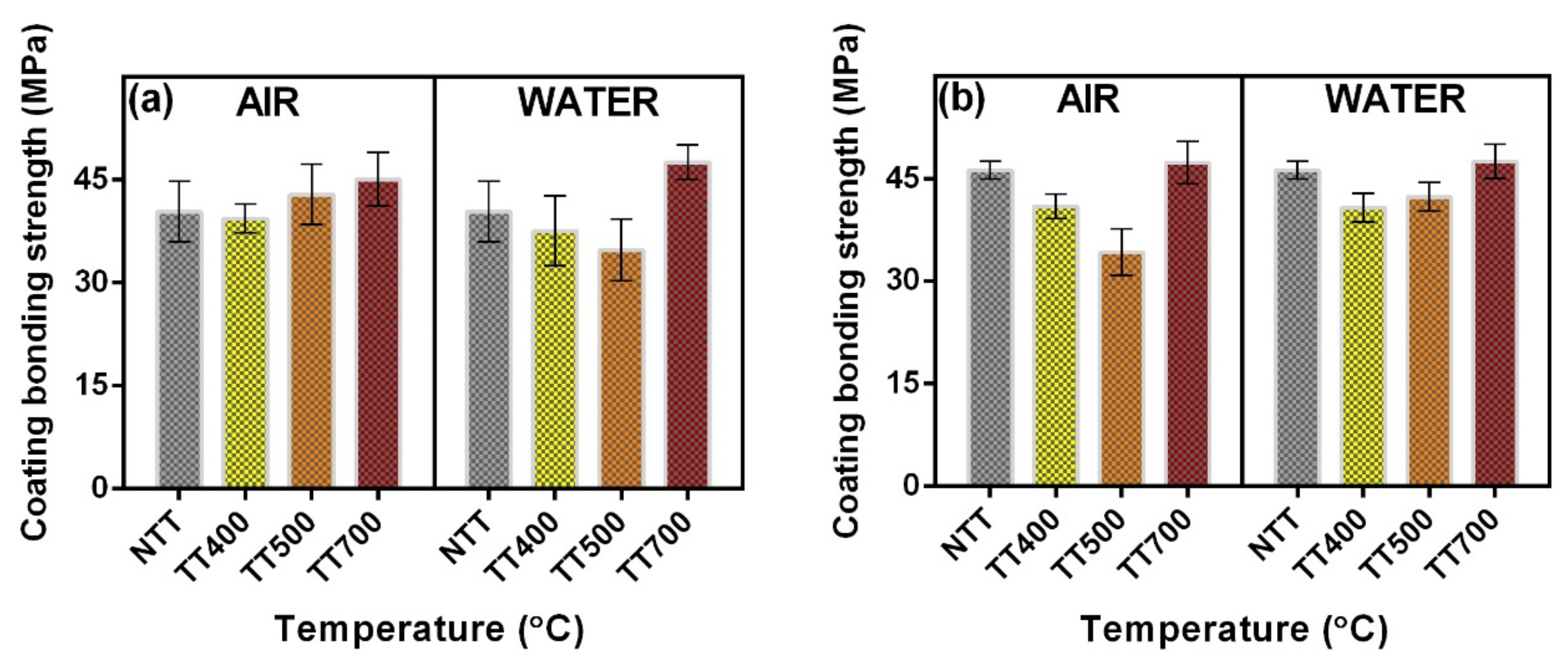
3.7. Pull-Out Bonding Strength Tests

The bonding force at the film–substrate interface is recognized as a key-parameter in the manufacturing process of high-quality implants [76], as it regulates both their initial stability and long-term functionality [48,77,78].
Prior to starting the measurements, four tests to control the quality of the bonding adhesive using bare Ti substrates (control) were performed under identical conditions. The results of all measurements performed at the stainless-steel test element–control Ti interface were in accordance with the specifications provided by the manufacturer.
In Figure 17, the results of the adherence tests (calculated as mean ± SD) in the case of NTT LiC and LiP coatings, and of those subjected to post-deposition thermal treatments (at different temperatures), in air and water-vapor ambient are presented. It should be mentioned that, for these measurements, there were considered the events when the fracturing was of adhesive type only, i.e., it occurred at the coating–Ti substrate interface.
It is interesting to observe from the data presented in Figure 17 that there exist two trends: (i) an increase of the adherence values with the applied temperature, in the case of LiC coatings subjected to post-deposition thermal treatments in air (Figure 17a), and LiP ones subjected to post-deposition thermal treatments in water-vapor ambient (Figure 15b), and (ii) a decrease of the adherence values for NTT–TT500 coatings, followed by an increase towards higher temperatures, both in the case of LiC coatings subjected to post-deposition thermal treatments in water-vapor ambient (Figure 17a) and LiP ones subjected to post-deposition thermal treatments in air (Figure 17b). A possible explanation for the increase of the adherence values with the applied temperature can be attributed to the processes of atomic inter-diffusion at the coating–Ti substrate interface, which occur during the post-deposition thermal treatments. Therefore, metallic ions can decrease the porosity of the samples, which can eventually lead to much more compact and hard structures [79].
It is important to mention that according to Ref. [76], adherence values exceeding 15 MPa are considered acceptable for the use of these structures as coatings for metallic implants. According to this criterion, the measured adherence values in the case of LiC and LiP coatings (more than three times higher than the imposed standard) should be therefore considered remarkable.

4. Conclusions

Hydroxyapatite (HA) of biological-origin doped with lithium carbonate (LiC) and lithium phosphate (LiP) coatings were synthesized by Pulsed laser deposition technique onto Ti6Al4V substrates, fabricated by additive manufacturing technique. The role of the post-deposition thermal treatments, performed in the range 400–700 °C (TT400–TT700) on the physical–chemical and mechanical characteristics of the synthesized coatings was thoroughly assessed and compared with the case of non-thermally treated (NTT) coatings.
From the structural, morphological, compositional, wetting behavior and mechanical points of view, the best overall properties were obtained in the case of both LiC and LiP synthesized coatings, submitted to the highest post-deposition thermal treatment temperature (i.e., 700 °C), in a water-vapor ambient. In addition, one should emphasize that the surface coating of orthopedic and dental implants, fabricated from medical-grade Ti alloys, with adherent bioceramic layers obtained from sustainable resources doped with Lithium is expected to foster the development of a new generation of osseous implants, which will (i) harmoniously couple the excellent mechanical properties of the metallic substrate with the proven capacity of the Lithium-doped bioceramic to both improve cell adhesion and differentiation, and induce fast osseointegration rates, and (ii) reduce the risk of bio-functional coating mechanical failure reported for the commercially available thick layers (i.e., hundreds of micrometers to millimeters range coatings fabricated by plasma spray). By combining Li-doped bioceramics with various polymers, one can obtain novel biomaterials with proper flexibility (i.e., bio-ink used in 3D printing for clinical applications of tissue engineering). Such types of Li-doped biomaterials might have a significant clinical potential in the predicted future.

Author Contributions

Conceptualization, L.D.; methodology, L.D. and G.E.S.; software, L.D. and G.E.S.; validation, L.D., G.E.S., G.P.-P., I.Z., M.A. and F.N.O.; formal analysis, L.D.; investigation, L.D., G.E.S., G.P.-P., I.Z. and M.A.; resources, L.D. and F.N.O.; data curation, L.D., G.E.S., G.P.-P., I.Z. and M.A.; writing—original draft preparation, L.D.; writing—review and editing, L.D., G.E.S., G.P.-P., I.Z., M.A. and F.N.O.; visualization, L.D., G.E.S., G.P.-P., I.Z., M.A. and F.N.O.; supervision, L.D.; project administration, L.D.; funding acquisition, L.D. All authors have read and agreed to the published version of the manuscript.

Funding

This research received no external funding.

Institutional Review Board Statement

Not applicable.

Informed Consent Statement

Not applicable.

Data Availability Statement

Not applicable.

Acknowledgments

L.D. acknowledges the support from two grants of the Romanian Ministry of Education and Research, CNCS-UEFISCDI, project numbers PN-III-P1-1.1-PD-2016-1568 (PD 6/2018) and PN-III-P1-1.1-TE2019-1449 (TE 189/2021), within PNCDI III. L.D and G.P.P. acknowledge the partial support from the Romanian Ministry of Education and Research, under Romanian National Core Program LAPLAS VI—Contract 16N/2019. G.E.S. and I.Z. acknowledge the partial support from the Romanian Ministry of Education and Research, under Romanian National Core Programme 21N. All authors thank A.C. Popescu and D. Chioibasu for the fabrication of the Ti6Al4V substrates.

Conflicts of Interest

The authors declare no conflict of interest.

References

  1. Denry, I.; Kuhn, L.T. Design and characterization of calcium phosphate ceramic scaffolds for bone tissue engineering. Dent. Mater. 2016, 32, 43–53. [Google Scholar] [CrossRef] [Green Version]
  2. Allied Market Research. Dental Implants and Prosthetics Market by Products (Dental Implants, Dental Prosthetics), by Materials (Metals, Polymers, Ceramics, Biomaterial): Global Opportunity Analysis and Industry Forecast, 2020–2030. Available online: https://www.alliedmarketresearch.com/dental-implants-and-prosthetics-market (accessed on 3 November 2022).
  3. Allied Market Research. Orthopedic Implants Market Expected to Reach $68.80 Billion by 2030. Available online: https://www.alliedmarketresearch.com/press-release/orthopedic-implants-market.html (accessed on 3 November 2022).
  4. Medany, S.S.; Elkamel, R.S.; Abdel-Gawad, S.A.; Fekry, A.M. A Novel Nano-Composite CSNPs/PVP/CoONPs Coating for Improving Corrosion Resistance of Ti-6Al-4V Alloy as a Dental Implant. Metals 2022, 12, 1784. [Google Scholar] [CrossRef]
  5. Hulka, I.; Florido-Suarez, N.R.; Mirza-Rosca, J.C.; Saceleanu, A. Mechanical Properties and Corrosion Behavior of Thermally Treated Ti-6Al-7Nb Dental Alloy. Materials 2022, 15, 3813. [Google Scholar] [CrossRef] [PubMed]
  6. Banerjee, D.; Williams, J.C. Perspectives on titanium science and technology. Acta Mater. 2013, 61, 844–879. [Google Scholar] [CrossRef]
  7. Agius, D.; Kourousis, K.I.; Wallbrink, C. A review of the as-built SLM Ti-6Al-4V mechanical properties towards achieving fatigue resistant designs. Metals 2018, 8, 75. [Google Scholar] [CrossRef] [Green Version]
  8. Rau, J.V.; Fadeeva, I.V.; Forysenkova, A.A.; Davydova, G.A.; Fosca, M.; Filippov, Y.Y.; Antoniac, I.V.; Antoniac, A.; D’Arco, A.; Di, M.; et al. Strontium Substituted Tricalcium Phosphate Bone Cement: Short and Long-Term Time-Resolved Studies and In Vitro Properties. Adv. Mater. Interfaces 2022, 9, 2200803. [Google Scholar] [CrossRef]
  9. Sargeant, A.; Goswami, T. Hip implants-Paper VI-Ion concentrations. Mater. Des. 2007, 28, 155–171. [Google Scholar] [CrossRef]
  10. Koch, C.; Johnson, S.; Kumar, D.; Jelinek, M.; Chrisey, D.; Doraiswamy, A.; Jin, C.; Narayan, R.J.; Mihailescu, I.N. Pulsed laser deposition of hydroxyapatite thin films. Mater. Sci. Eng. C 2007, 27, 484–494. [Google Scholar] [CrossRef]
  11. Ananth, H.; Kundapur, V.; Mohammed, H.S.; Anand, M.; Amarnath, G.S.; Mankar, S. A review on biomaterials in dental implantology. Int. J. Biomed. Sci. 2015, 11, 113–120. [Google Scholar]
  12. Li, J.; Yang, L.; Guo, X.; Cui, W.; Yang, S.; Wang, J.; Qu, Y.; Shao, Z.; Xu, S. Osteogenesis effects of strontium-substituted hydroxyapatite coatings on true bone ceramic surfaces in vitro and in vivo. Biomed. Mater. 2018, 13, 015018. [Google Scholar] [CrossRef]
  13. Oktar, F.N.; Unal, S.; Gunduz, O.; Nissan, B.B.; Macha, I.J.; Akyol, S.; Duta, L.; Ekren, N.; Altan, E.; Yetmez, M. Marine-derived bioceramics for orthopedic, reconstructive and dental surgery applications. J. Aust. Ceram. Soc. 2022. [Google Scholar] [CrossRef]
  14. Akram, M.; Ahmed, R.; Shakir, I.; Ibrahim, W.A.W.; Hussain, R. Extracting hydroxyapatite and its precursors from natural resources. J. Mater. Sci. 2014, 49, 1461–1475. [Google Scholar] [CrossRef]
  15. Wang, B.; Feng, C.; Liu, Y.; Mi, F.; Dong, J. Recent advances in biofunctional guided bone regeneration materials for repairing defective alveolar and maxillofacial bone: A review. Jpn. Dent. Sci. Rev. 2022, 58, 233–248. [Google Scholar] [CrossRef]
  16. Qiao, W.; Liu, Q.; Li, Z.; Zhang, H.; Chen, Z. Changes in physicochemical and biological properties of porcine bone derived hydroxyapatite induced by the incorporation of fluoride. Sci. Technol. Adv. Mater. 2017, 18, 110–121. [Google Scholar] [CrossRef] [PubMed] [Green Version]
  17. Zhou, H.; Lee, J. Nanoscale hydroxyapatite particles for bone tissue engineering. Acta Biomater. 2011, 7, 2769–2781. [Google Scholar] [CrossRef] [PubMed]
  18. Inoue, M.; Rodriguez, A.P.; Nagai, N.; Nagatsuka, H.; LeGeros, R.Z.; Tsujigiwa, H.; Inoue, M.; Kishimoto, E.; Takagi, S. Effect of Fluoride-substituted Apatite on In Vivo Bone Formation. J. Biomater. Appl. 2011, 25, 811–824. [Google Scholar] [CrossRef] [PubMed]
  19. Eason, R. Pulsed Laser Deposition of Thin Films: Applications-Led Growth of Functional Materials, 1st ed.; Wiley & Sons Interscience: Hoboken, NJ, USA, 2007; pp. 1–705. [Google Scholar]
  20. Montazerian, M.; Hosseinzadeh, F.; Migneco, C.; Fook, M.V.L.; Baino, F. Bioceramic coatings on metallic implants: An overview. Ceram. Int. 2022, 48, 8987–9005. [Google Scholar] [CrossRef]
  21. Duta, L.; Popescu, A.C. Current Status on Pulsed Laser Deposition of Coatings from Animal-Origin Calcium Phosphate Sources. Coatings 2019, 9, 335. [Google Scholar] [CrossRef] [Green Version]
  22. Duta, L. In Vivo Assessment of Synthetic and Biological-Derived Calcium Phosphate-Based Coatings Fabricated by Pulsed Laser Deposition: A Review. Coatings 2021, 11, 99. [Google Scholar] [CrossRef]
  23. Duta, L.; Oktar, F.N.; Stan, G.E.; Popescu-Pelin, G.; Serban, N.; Luculescu, C.; Mihailescu, I.N. Novel doped hydroxyapatite thin films obtained by pulsed laser deposition. Appl. Surf. Sci. 2013, 265, 41–49. [Google Scholar] [CrossRef]
  24. Graziani, G.; Boi, M.; Bianchi, M. A Review on Ionic Substitutions in Hydroxyapatite Thin Films: Towards Complete Biomimetism. Coatings 2018, 8, 269. [Google Scholar] [CrossRef]
  25. Farmani, A.R.; Salmeh, M.A.; Golkar, Z.; Moeinzadeh, A.; Ghiasi, F.F.; Amirabad, S.Z.; Shoormeij, M.H.; Mahdavinezhad, F.; Momeni, S.; Moradbeygi, F.; et al. Li-Doped Bioactive Ceramics: Promising Biomaterials for Tissue Engineering and Regenerative Medicine. J. Funct. Biomater. 2022, 13, 162. [Google Scholar] [CrossRef] [PubMed]
  26. Duta, L.; Chifiriuc, M.C.; Popescu-Pelin, G.; Bleotu, C.; Gradisteanu, G.(P.); Anastasescu, M.; Achim, A.; Popescu, A. Pulsed Laser Deposited Biocompatible Lithium-Doped Hydroxyapatite Coatings with Antimicrobial Activity. Coatings 2019, 9, 54. [Google Scholar] [CrossRef] [Green Version]
  27. Glenske, K.; Donkiewicz, P.; Köwitsch, A.; Milosevic-Oljaca, N.; Rider, P.; Rofall, S.; Franke, J.; Jung, O.; Smeets, R.; Schnettler, R.; et al. Applications of Metals for Bone Regeneration. Int. J. Mol. Sci. 2018, 19, 826. [Google Scholar] [CrossRef] [PubMed] [Green Version]
  28. Mayer, I.; Berger, U.; Markitziu, A.; Gidalia, I. The uptake of lithium ions by synthetic carbonated hydroxyapatite. Calcif. Tissue Int. 1986, 38, 293–295. [Google Scholar] [CrossRef]
  29. Koutsoukos, P.G.; Nancollas, G.H. The effect of lithium on the precipitation of hydroxyapatite from aqueous solutions. Colloids Surf. 1986, 17, 361–370. [Google Scholar] [CrossRef]
  30. Shainberg, A.P.M.; Valério, P.; Zonari, A.; Oktar, F.N.; Ozyegin, L.S.; Graça, M.P.F.; Leite, M.F.; Goes, A.M. Attachment and proliferation of osteoblasts on lithium-hydroxyapatite composites. Adv. Mater. Sci. Eng. 2012, 2012, 650574. [Google Scholar] [CrossRef] [Green Version]
  31. Popescu, A.C.; Florian, P.E.; Stan, G.E.; Popescu-Pelin, G.; Zgura, I.; Enculescu, M.; Oktar, F.N.; Trusca, R.; Sima, L.E.; Roseanu, A.; et al. Physical-chemical characterization and biological assessment of simple and lithium-doped biological-derived hydroxyapatite thin films for a new generation of metallic implants. Appl. Surf. Sci. 2018, 439, 724–735. [Google Scholar] [CrossRef]
  32. Florian, P.E.; Duta, L.; Grumezescu, V.; Popescu-Pelin, G.; Popescu, A.C.; Oktar, F.N.; Evans, R.W.; Constantinescu, A.R. Lithium-Doped Biological-Derived Hydroxyapatite Coatings Sustain In Vitro Differentiation of Human Primary Mesenchymal Stem Cells to Osteoblasts. Coatings 2019, 9, 781. [Google Scholar] [CrossRef] [Green Version]
  33. Sakudo, A. Inactivation Methods for Prions. Curr. Issues Mol. Biol. 2020, 36, 23–32. [Google Scholar] [CrossRef] [Green Version]
  34. Chioibasu, D.; Achim, A.; Popescu, C.; Stan, G.E.; Pasuk, I.; Enculescu, M.; Iosub, S.; Duta, L.; Popescu, A. Prototype Orthopedic Bone Plates 3D Printed by Laser Melting Deposition. Materials 2019, 12, 906. [Google Scholar] [CrossRef] [PubMed]
  35. Stan, G.E.; Marcov, D.A.; Popa, A.C.; Husanu, M.A. Polymer-like and diamond-like carbon coatings prepared by RF-PECVD for biomedical applications. Dig. J. Nanomater. Biostruct. 2010, 5, 705–718. [Google Scholar]
  36. Owens, D.K.; Wendt, R.C. Estimation of the surface free energy of polymers. J. Appl. Polym. Sci. 1969, 13, 1741–1747. [Google Scholar] [CrossRef]
  37. Popa, A.C.; Stan, G.E.; Husanu, M.A.; Pasuk, I.; Popescu, I.D.; Popescu, A.C.; Mihailescu, I.N. Multi-layer haemocompatible diamond-like carbon coatings obtained by combined radio frequency plasma enhanced chemical vapor deposition and magnetron sputtering. J. Mater. Sci. Mater. Med. 2013, 24, 2695–2707. [Google Scholar] [CrossRef] [PubMed]
  38. Stan, G.E.; Morosanu, C.O.; Marcov, D.A.; Pasuk, I.; Miculescu, F.; Reumont, G. Effect of annealing upon the structure and adhesion properties of sputtered bio-glass/titanium coatings. Appl. Surf. Sci. 2009, 255, 9132–9138. [Google Scholar] [CrossRef]
  39. Hench, L.L. Bioceramics: From Concept to Clinic. J. Am. Ceram. Soc. 1991, 74, 1487–1510. [Google Scholar] [CrossRef] [Green Version]
  40. Pasteris, J.D.; Wopenka, B.; Freeman, J.J.; Rogers, K.; Valsami-Jones, E.; van der Houwen, J.A.M.; Silva, M.J. Lack of OH in nanocrystalline apatite as a function of degree of atomic order: Implications for bone and biomaterials. Biomaterials 2004, 25, 229–238. [Google Scholar] [CrossRef]
  41. Cihlář, J.; Buchal, A.; Trunec, M. Kinetics of thermal decomposition of hydroxyapatite bioceramics. J. Mater. Sci. 1999, 34, 6121–6131. [Google Scholar] [CrossRef]
  42. Komur, B.; Lohse, T.; Can, H.M.; Khalilova, G.; Geçimli, Z.N.; Aydoğdu, M.O.; Kalkandelen, C.; Stan, G.E.; Sahin, Y.M.; Sengil, A.Z.; et al. Fabrication of naturel pumice/hydroxyapatite composite for biomedical engineering. Bio. Med. Eng. OnLine 2016, 15, 81. [Google Scholar] [CrossRef] [Green Version]
  43. Patterson, A.L. The Scherrer Formula for X-Ray Particle Size Determination. Phys. Rev. 1939, 56, 978. [Google Scholar] [CrossRef]
  44. Markovic, M.; Fowler, B.O.; Tung, M.S. Preparation and Comprehensive Characterization of a Calcium Hydroxyapatite Reference Material. J. Res. Natl. Inst. Stand. Technol. 2004, 109, 553–568. [Google Scholar] [CrossRef] [PubMed]
  45. Chirică, I.M.; Enciu, A.-M.; Tite, T.; Dudău, M.; Albulescu, L.; Iconaru, S.L.; Predoi, D.; Pasuk, I.; Enculescu, M.; Radu, C.; et al. The Physico-Chemical Properties and Exploratory Real-Time Cell Analysis of Hydroxyapatite Nanopowders Substituted with Ce, Mg, Sr, and Zn (0.5–5 at.%). Materials 2021, 14, 3808. [Google Scholar] [CrossRef] [PubMed]
  46. Gadaleta, S.J.; Paschalis, E.P.; Betts, F.; Mendelsohn, R.; Boskey, A.L. Fourier transform infrared spectroscopy of the solution-mediated conversion of amorphous calcium phosphate to hydroxyapatite: New correlations between X-ray diffraction and infrared data. Calcif. Tissue Int. 1996, 58, 9–16. [Google Scholar] [CrossRef] [PubMed]
  47. Querido, W.; Shanas, N.; Bookbinder, S.; Oliveira-Nunes, M.C.; Krynska, B.; Pleshko, N. Fourier transform infrared spectroscopy of developing bone mineral: From amorphous precursor to mature crystal. Analyst 2020, 145, 764–776. [Google Scholar] [CrossRef] [PubMed]
  48. Sima, L.E.; Stan, G.E.; Morosanu, C.O.; Melinescu, A.; Ianculescu, A.; Melinte, R.; Neamtu, J.; Petrescu, S.M. Differentiation of mesenchymal stem cells onto highly adherent radio frequency-sputtered carbonated hydroxylapatite thin films. J. Biomed. Mater. Res. A 2010, 95A, 1203–1214. [Google Scholar] [CrossRef] [PubMed]
  49. Visan, A.; Grossin, D.; Stefan, N.; Duta, L.; Miroiu, F.M.; Stan, G.E.; Sopronyi, M.; Luculescu, C.; Freche, M.; Marsan, O.; et al. Biomimetic nanocrystalline apatite coatings synthesized by matrix assisted pulsed laser evaporation for medical applications. Mater. Sci. Eng. B 2014, 181, 56–63. [Google Scholar] [CrossRef] [Green Version]
  50. Spence, G.; Phillips, S.; Campion, C.; Brooks, R.; Rushton, N. Bone formation in a carbonate-substituted hydroxyapatite implant is inhibited by zoledronate. J. Bone Joint Surg. Br. 2008, 90-B, 1635–1640. [Google Scholar] [CrossRef]
  51. Germaini, M.M.; Detsch, R.; Grünewald, A.; Magnaudeix, A.; Lalloue, F.; Boccaccini, A.R.; Champion, E. Osteoblast and osteoclast responses to A/B type carbonate-substituted hydroxyapatite ceramics for bone regeneration. Biomed. Mater. 2017, 12, 035008. [Google Scholar] [CrossRef]
  52. Peng, G.W.; Chen, S.K.; Liu, H.S. Infrared Absorption Spectra and Their Correlation with the Ti-O Bond Length Variations for TiO2 (Rutile), Na-Titanates, and Na-Titanosilicate (Natisite, Na2TiOSiO4). App. Spectrosc. 1995, 49, 1646–1651. [Google Scholar] [CrossRef]
  53. Šupová, M. Substituted hydroxyapatites for biomedical applications: A review. Ceram. Int. 2015, 41, 9203–9231. [Google Scholar] [CrossRef]
  54. Lescoute, E.; Hallo, L.; Hébert, D.; Chimier, B.; Etchessahar, B.; Tikhonchuk, V.T.; Chevalier, J.M.; Combis, P. Experimental observations and modeling of nanoparticle formation in laser-produced expanding plasma. Phys. Plasmas 2008, 15, 063507. [Google Scholar] [CrossRef] [Green Version]
  55. Mihailescu, I.N.; Ristoscu, C.; Bigi, A.; Mayer, I. Advanced biomimetic implants based on nanostructured coatings synthesized by pulsed laser technologies. In Laser-Surface Interactions for New Materials Production, Tailoring Structure and Properties; Miotello, A., Ossi, M., Eds.; Springer: New York, NY, USA, 2010; pp. 235–268. [Google Scholar]
  56. Hacking, S.A.; Boyraz, P.; Powers, B.M.; Sen-Gupta, E.; Kucharski, W.; Brown, C.A.; Cook, E.P. Surface roughness enhances the osseointegration of titanium headposts in non-human primates. J. Neurosci. Methods 2012, 211, 237–244. [Google Scholar] [CrossRef] [PubMed]
  57. Dinda, G.P. Pulsed laser deposition of hydroxyapatite thin films on Ti–6Al–4V: Effect of heat treatment on structure and properties. Acta Biomater. 2009, 5, 1821–1830. [Google Scholar] [CrossRef] [PubMed]
  58. Lu, Y.P.; Li, S.T.; Zhu, R.F.; Li, M.S.; Lei, T.Q. Formation of ultrafine particles in heat treated plasma-sprayed hydroxyapatite coatings. Surf. Coating Technol. 2003, 165, 65–70. [Google Scholar] [CrossRef]
  59. Whitehouse, D.J. Surface Characterization and Roughness Measurement in Engineering. In Photomechanics; Rastogi, P.K., Ed.; Topics in Applied Physics; Springer: Berlin/Heidelberg, Germany, 2000; Volume 77. [Google Scholar] [CrossRef]
  60. Kubiak, K.J.; Wilson, M.C.T.; Mathia, T.G.; Carval, P. Wettability versus roughness of engineering surfaces. Wear 2011, 271, 523–528. [Google Scholar] [CrossRef] [Green Version]
  61. Duta, L.; Popescu, A.C.; Zgura, I.; Preda, N.; Mihailescu, I.N. Wettability of Nanostructured Surfaces. In Wetting and Wettability; Aliofkhazraei, M., Ed.; Intech: Vienna, Austria, 2015. [Google Scholar] [CrossRef] [Green Version]
  62. US National Institute of Standards and Technology (NIST) e-Handbook of Statistical Methods. Available online: https://www.itl.nist.gov/div898/handbook (accessed on 2 November 2022).
  63. Sedlacek, M.; Vilhena, L.M.S.; Podgornik, B.; Vizintin, J. Surface topography modelling for reduced friction. J. Mech. Eng. 2011, 57, 674–680. [Google Scholar] [CrossRef] [Green Version]
  64. Stan, G.E.; Popescu, A.C.; Mihailescu, I.N.; Marcov, D.A.; Mustata, R.C.; Sima, L.E.; Petrescu, S.M.; Ianculescu, A.; Trusca, R.; Morosanu, C.O. On the bioactivity of adherent bioglass thin films synthesized by magnetron sputtering techniques. Thin Solid Films 2010, 518, 5955–5964. [Google Scholar] [CrossRef]
  65. Gadelmawla, E.S.; Koura, M.M.; Maksoud, T.M.A.; Elewa, I.M.; Soliman, H.H. Roughness parameters. J. Mater. Process Technol. 2002, 123, 133–145. [Google Scholar] [CrossRef]
  66. Liu, H.; Yazici, H.; Ergun, C.; Webster, T.J.; Bermek, H. An in vitro evaluation of the Ca/P ratio for the cytocompatibility of nano-to-micron particulate calcium phosphates for bone regeneration. Acta Biomater. 2008, 4, 1472–1479. [Google Scholar] [CrossRef]
  67. León, B.; Jansen, J.A. Thin Calcium Phosphate Coatings for Medical Implants; Springer Science + Business Media: New York, NY, USA, 2009; pp. 1–328. [Google Scholar]
  68. Surmenev, R.A.; Surmeneva, M.A.; Evdokimov, K.E.; Pichugin, V.F.; Peitsch, T.; Epple, M. The influence of the deposition parameters on the properties of an rf-magnetron-deposited nanostructured calcium phosphate coating and a possible growth mechanism. Surf. Coat. Technol. 2011, 205, 3600–3606. [Google Scholar] [CrossRef]
  69. Sameer, R.P.; Zheng, C.; Wei, H.; Narendra, B.D. Wetting effects on in vitro bioactivity and in vitro biocompatibility of laser micro-textured Ca-P coating. Biofabrication 2010, 2, 025001. [Google Scholar] [CrossRef]
  70. Wilson, C.J.; Clegg, R.E.; Leavesley, D.I.; Mark, A.; Pearcy, J. Mediation of biomaterial-cell interactions by adsorbed proteins: A review. Tissue Eng. 2005, 11, 1–18. [Google Scholar] [CrossRef] [PubMed]
  71. Okabe, Y.; Kurihara, S.; Yajima, T.; Seki, Y.; Nakamura, I.; Takano, I. Formation of super-hydrophilic surface of hydroxyapatite by ion implantation and plasma treatment. Surf. Coat. Technol. 2005, 196, 303–306. [Google Scholar] [CrossRef]
  72. Lotfi, M.; Nejib, M.; Naceur, M. Cell Adhesion to Biomaterials: Concept of Biocompatibility. In Advances in Biomaterials Science and Biomedical Applications; Pignatello, R., Ed.; Intech: Rijeka, Croatia, 2013; pp. 207–240. [Google Scholar] [CrossRef] [Green Version]
  73. Gentleman, M.M.; Gentleman, E. The role of surface free energy in osteoblast-biomaterial interactions. Int. Mater. Rev. 2014, 59, 417–429. [Google Scholar] [CrossRef]
  74. Pessková, V.; Kubies, D.; Hulejova, H.; Himmlova, L. The influence of implant surface properties on cell adhesion and proliferation. J. Mater. Sci. Mater. Med. 2007, 18, 465–473. [Google Scholar] [CrossRef]
  75. Mitra, J.; Tripathi, G.; Sharma, A.; Basu, B. Scaffolds for bone tissue engineering: Role of surface patterning on osteoblast response. RSC Adv. 2013, 3, 11073–11094. [Google Scholar] [CrossRef]
  76. ISO 13779-2; Implants for Surgery—Hydroxyapatite—Part 2: Coatings of Hydroxyapatite. ISO: Geneva, Switzerland, 2018.
  77. Popa, A.C.; Stan, G.E.; Enculescu, M.; Tanase, C.; Tulyaganov, D.U.; Ferreira, J.M.F. Superior biofunctionality of dental implant fixtures uniformly coated with durable bioglass films by magnetron sputtering. J. Mech. Behav. Biomed. Mater. 2015, 51, 313–327. [Google Scholar] [CrossRef]
  78. Stan, G.E.; Popa, A.C.; Galca, A.C.; Aldica, G.; Ferreira, J.M.F. Strong bonding between sputtered bioglass-ceramic films and Ti-substrate implants induced by atomic inter-diffusion post-deposition heat-treatments. Appl. Surf. Sci. 2013, 280, 530–538. [Google Scholar] [CrossRef]
  79. Wang, Y.; Yang, X.; Gu, Z.; Qin, H.; Li, L.; Liu, J.; Yu, X. In vitro study on the degradation of lithium-doped hydroxyapatite for bone tissue engineering scaffold. Mater. Sci. Eng. C Mater. Biol. Appl. 2016, 66, 185–192. [Google Scholar] [CrossRef]
Figure 1. The GIXRD patterns of the NTT and TT (a) LiC- and (b) LiP-type coatings, in air and water vapors ambient. The reference ICDD-PDF4 files of hydroxyapatite (No. 00-009-0432) and β-tricalcium phosphate (No. 00-009-0169) are presented at the bottom of the graphs for comparison.
Coatings 12 01883 g001
Figure 2. Average crystallite sizes determined by Scherrer equation along the (a) c-axis and (b) a-axis for the HA constituent phase of the LiC and LiP samples heat-treated in air and water-vapor ambient at 500 and 700 °C, respectively. (c) Crystallite shape anisotropy factors.
Coatings 12 01883 g002
Figure 3. The FTIR-ATR spectra of the NTT and TT (a) LiC- and (b) LiP-type coatings, in air and water-vapor ambient. The reference spectra of pure (commercial) hydroxyapatite and β-tricalcium phosphate compounds are presented at the bottom of the graphs for comparison.
Coatings 12 01883 g003
Figure 4. Top-view general and detailed SEM micrographs of control Ti, NTT LiC samples and of those subjected to post-deposition thermal treatments (at different temperatures), in air and water-vapor ambient, synthesized onto Ti substrates.
Coatings 12 01883 g004
Figure 5. Top-view general and detailed SEM micrographs of control Ti, NTT LiP samples and of those subjected to post-deposition thermal treatments (at different temperatures), in air and water-vapor ambient, synthesized onto Ti substrates.
Coatings 12 01883 g005
Figure 6. Cross-view SEM micrographs of control Ti, NTT LiC samples and of those subjected to post-deposition thermal treatments (at different temperatures), in air and water-vapor ambient, synthesized onto Si substrates.
Coatings 12 01883 g006
Figure 7. Cross-view SEM micrographs of control Ti, NTT LiP samples and of those subjected to post-deposition thermal treatments (at different temperatures), in air and water-vapor ambient, synthesized onto Si substrates.
Coatings 12 01883 g007
Figure 8. The 2D (classical view mode) and 3D (enhanced color view mode) AFM images of control Si, NTT LiC coatings and of those subjected to post-deposition thermal treatments (at different temperatures), in air (A–left columns) and water-vapor (W–right columns) ambient.
Coatings 12 01883 g008
Figure 9. The 2D (classical view mode) and 3D (enhanced color view mode) AFM images of control Si, NTT LiP coatings and of those subjected to post-deposition thermal treatments (at different temperatures), in air (A–left columns) and water-vapor (W–right columns) ambient.
Coatings 12 01883 g009
Figure 10. Roughness values inferred in the case of LiC (a) and LiP (b) coatings subjected to post-deposition thermal treatments (at different temperatures), in air and water-vapor ambient. Inset: detailed roughness values.
Coatings 12 01883 g010
Figure 11. The values of the contact angle obtained in the case of control (Ti), NTT LiC (a,b) and LiP (c,d) coatings, and of those subjected to post-deposition thermal treatments (at different temperatures), in air (a,c) and water-vapor (b,d) ambient. Test liquid: water.
Coatings 12 01883 g011
Figure 12. The values of the contact angle obtained in the case of control (Ti), NTT LiC (a,b) and LiP (c,d) coatings, and of those subjected to post-deposition thermal treatments (at different temperatures), in air (a,c) and water-vapor (b,d) ambient. Test liquid: diiodomethane.
Coatings 12 01883 g012
Figure 13. Representative images of the water droplets on control (Ti), NTT LiC and of those subjected to post-deposition thermal treatments (at different temperatures), in air and water-vapor ambient.
Coatings 12 01883 g013
Figure 14. Representative images of the water droplets on control (Ti), NTT LiP and of those subjected to post-deposition thermal treatments (at different temperatures), in air and water-vapor ambient.
Coatings 12 01883 g014
Figure 15. The surface free energy values recorded for the control (Ti), NTT LiC and for those subjected to post-deposition thermal treatments (at different temperatures), in air (a) and water-vapor (b) ambient.
Coatings 12 01883 g015
Figure 16. The surface free energy values recorded for the control (Ti), NTT LiP and for those subjected to post-deposition thermal treatments (at different temperatures), in air (a) and water-vapor (b) ambient.
Coatings 12 01883 g016
Figure 17. Mean bonding strength values recorded in the case of NTT LiC (a) and LiP (b) coatings, and of those subjected to post-deposition thermal treatments (at different temperatures), in air and water-vapor ambient.
Coatings 12 01883 g017
Table 1. Surface amplitude parameters (Rq, Rsk and Rku) for a (20 × 20 µm2) scanned surface area of control Si, NTT LiC and LiP coatings and of those subjected to post-deposition thermal treatments (at different temperatures), in air and water-vapor ambient.
Amplitude ParameterSi Control
Rq [nm]0.31
Rsk−40.59
Rku3606.86
 LiC
 Air
 NTTTT400TT500TT700
Rsk−2.11−1.56−2.27−6.49
Rku10.7613.2613.8053.05
 Water
 NTTTT400TT500TT700
Rsk−2.11−1.38−0.99−1.16
Rku10.765.096.166.50
 LiP
 Air
 NTTTT400TT500TT700
Rsk−3.61−1.54−1.21−3.38
Rku21.599.026.1517.04
 Water
 NTTTT400TT500TT700
Rsk−3.61−3.98−3.15−1.28
Rku21.5920.8021.285.65
Table 2. Ca/P atomic ratio corresponding to NTT LiC and LiP coatings, and of those subjected to post-deposition thermal treatments (at different temperatures), in air and water-vapor ambient.
ElementComposition [Mean ± SD (at.%)]
LiC
Air
NTTTT400TT500TT700
P6.7 ± 0.97.2 ± 0.66.3 ± 0.67.1 ± 0.3
Ca11.9 ± 3.512.6 ± 1.0510.8 ± 1.111.6 ± 0.7
Ca/P ratio1.76 ± 0.31.73 ± 0.11.71 ± 0.11.64 ± 0.1
 Water
 NTTTT400TT500TT700
P6.7 ± 0.96.4 ± 0.47.2 ± 0.87 ± 0.09
Ca11.9 ± 3.510.7 ± 0.813.3 ± 3.411.4 ± 0.3
Ca/P ratio1.76 ± 0.31.68 ± 0.11.85 ± 0.31.63 ± 0.1
 LiP
 Air
 NTTTT400TT500TT700
P7.6 ± 0.076.9 ± 0.67.2 ± 0.57.1 ± 0.3
Ca12.8 ± 0.311.2 ± 1.111.9 ± 0.811.6 ± 0.4
Ca/P ratio1.68 ± 0.11.60 ± 0.11.65 ± 0.11.62 ± 0.1
 Water
 NTTTT400TT500TT700
P7.6 ± 0.076.5 ± 0.37.2 ± 0.57.1 ± 0.5
Ca12.8 ± 0.310.5 ± 0.411.9 ± 0.812.2 ± 1.01
Ca/P ratio1.68 ± 0.11.61 ± 0.11.66 ± 0.11.71 ± 0.1
Publisher’s Note: MDPI stays neutral with regard to jurisdictional claims in published maps and institutional affiliations.

