
Improvement of the Tribocorrosion Properties of Cemented Carbide (WC-Tic-Co) Samples with PVD Coating
 , , , , and
Abstract
:1. Introduction
2. Materials and Methods
2.1. Reference Substrate
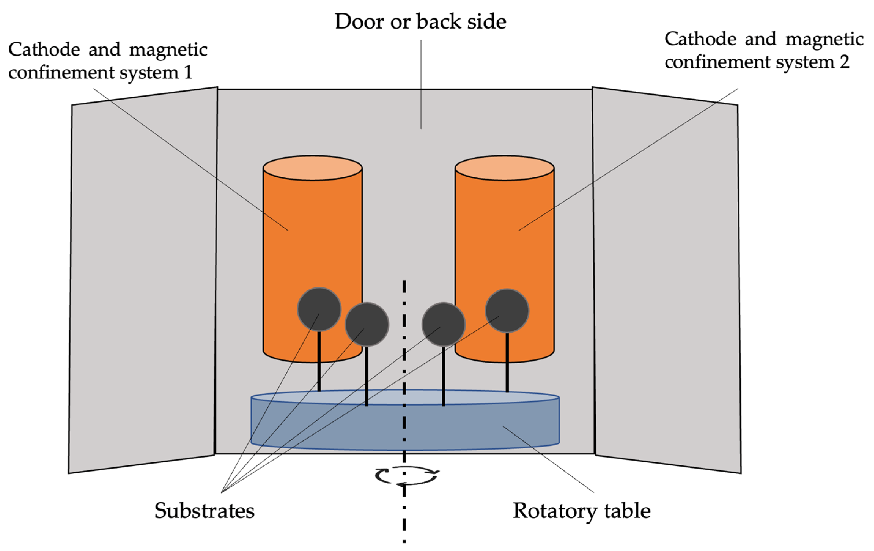
2.2. Film Deposition Technique
- Nitrogen atmosphere at 0.8–2 Pa
- Negative bias voltage of −65 V.
- Cr and Al + Si cathodes as material source.

2.3. Thickness, Structural Properties and Profile Composition
2.4. Surface and Mechanical Characterization
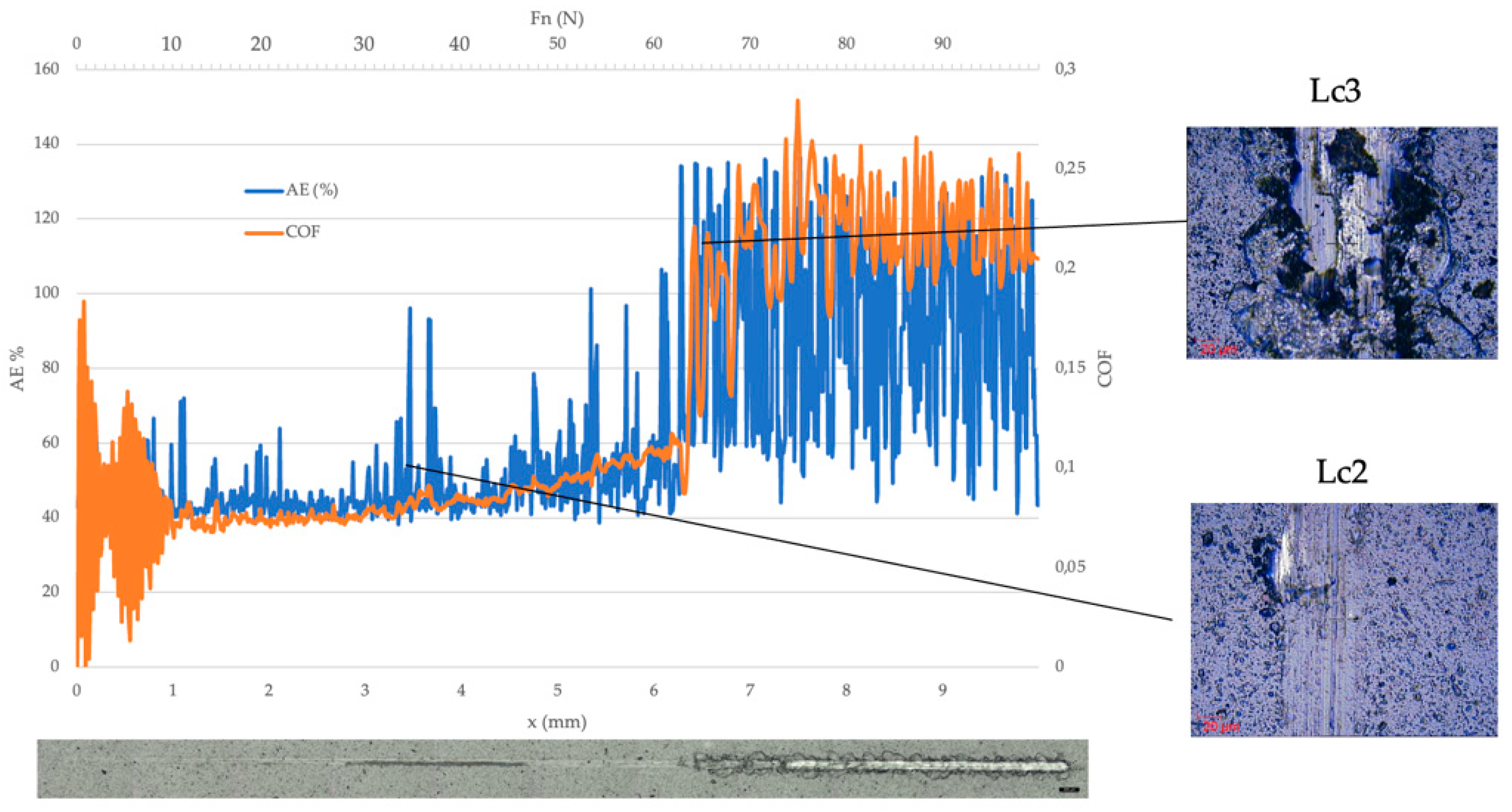
- First critical load (Lc1): it describes the first cohesive failure.
- Second critical load (Lc2): it is associated with the first adhesive failure appearance.
- Third critical load (Lc3): it is registered when total delamination of the coating or a critical defect is observed in a clear way in the reference substrate.
- Standard cut-off of the high-pass filter (λs): 2.50 μm
- Standard cut-off of the high-pass filter (λc): 0.08 mm
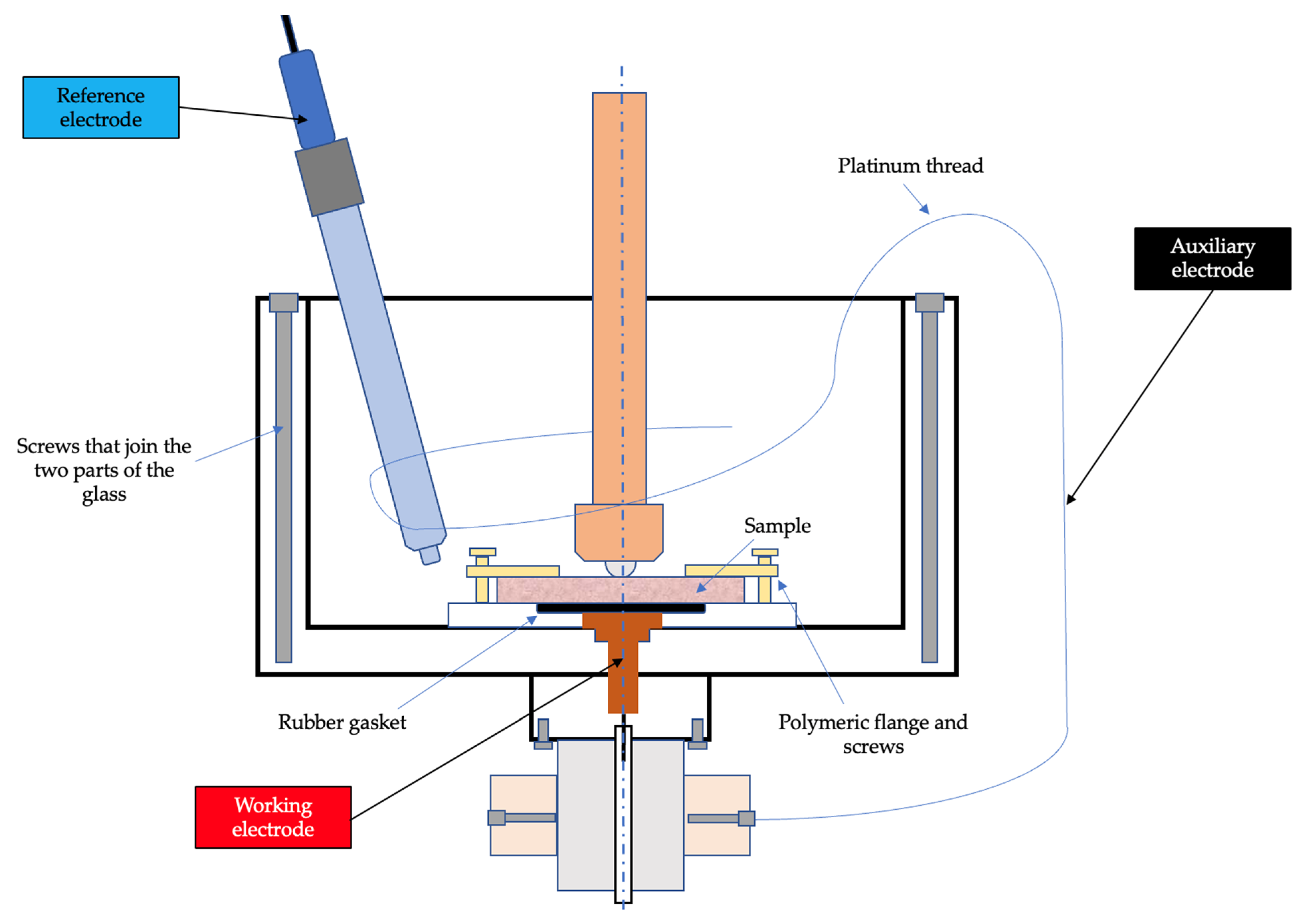
2.5. Corrosion and Tribocorrosion Tests
3. Results
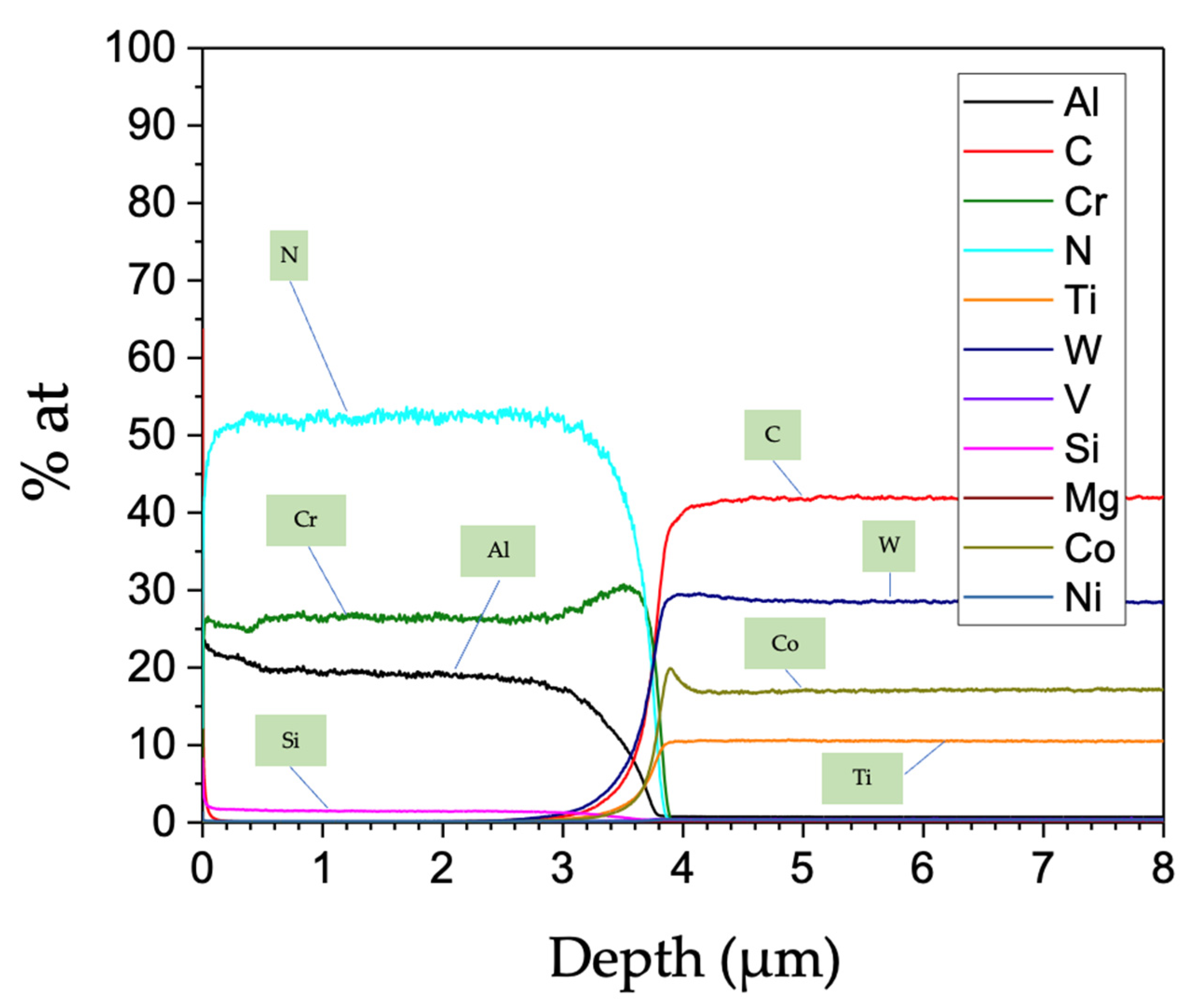
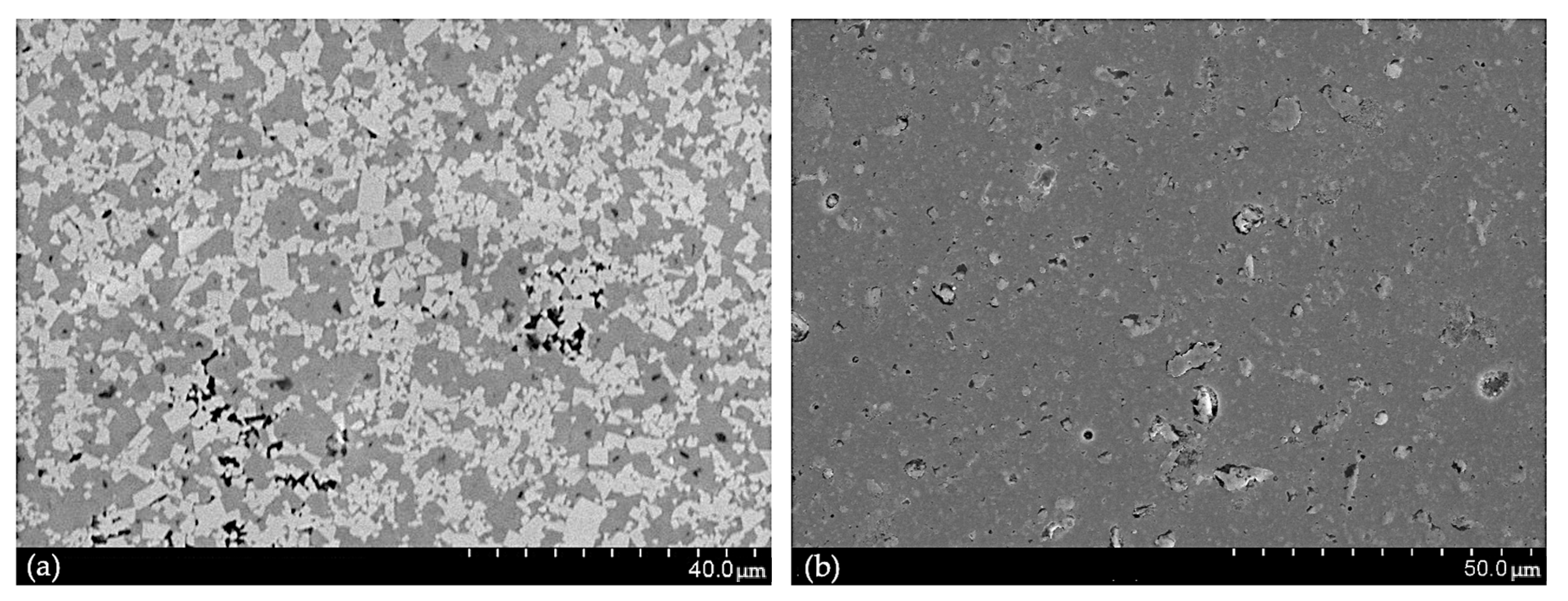
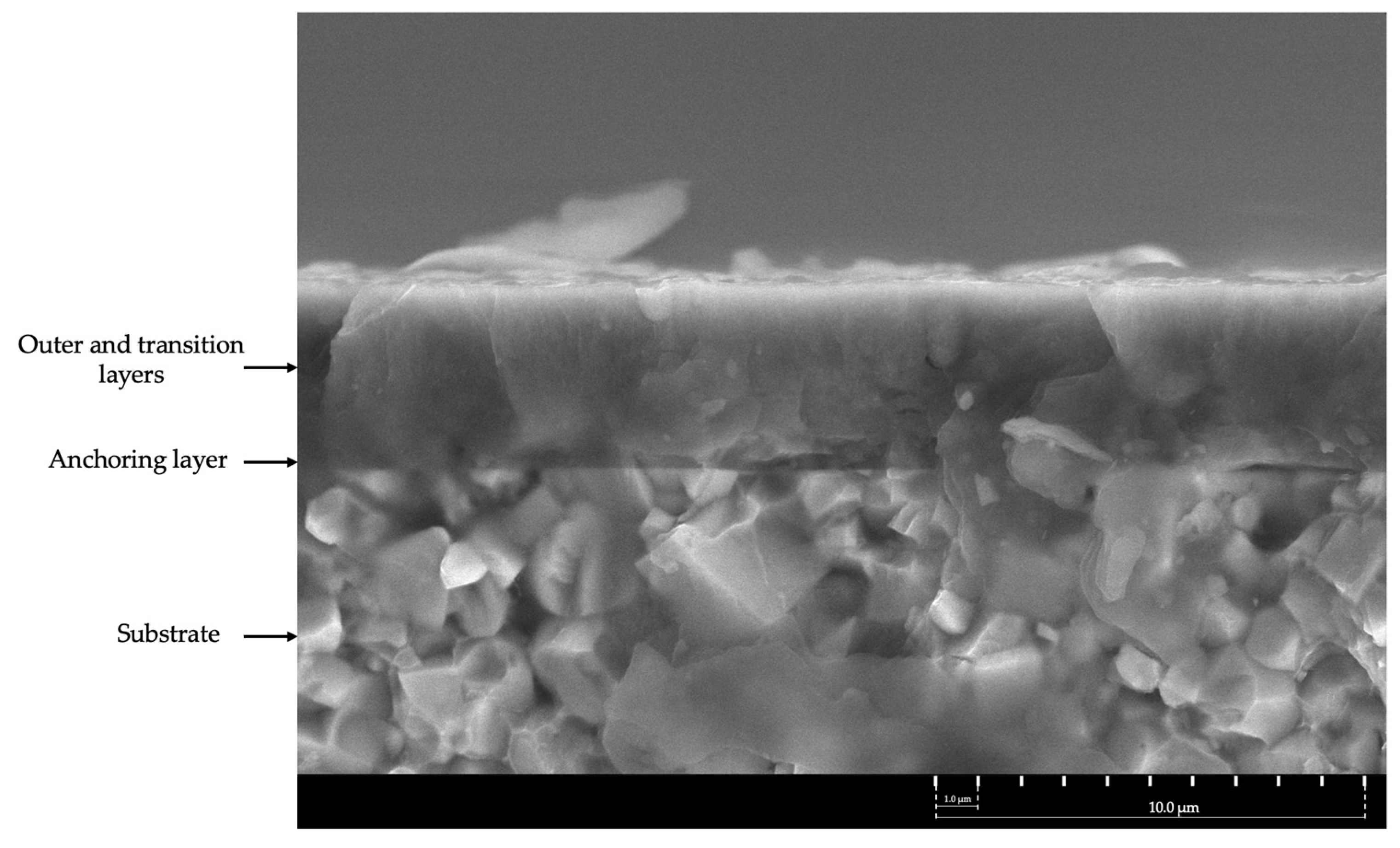
3.1. Thickness, Structural Properties and Profile Composition
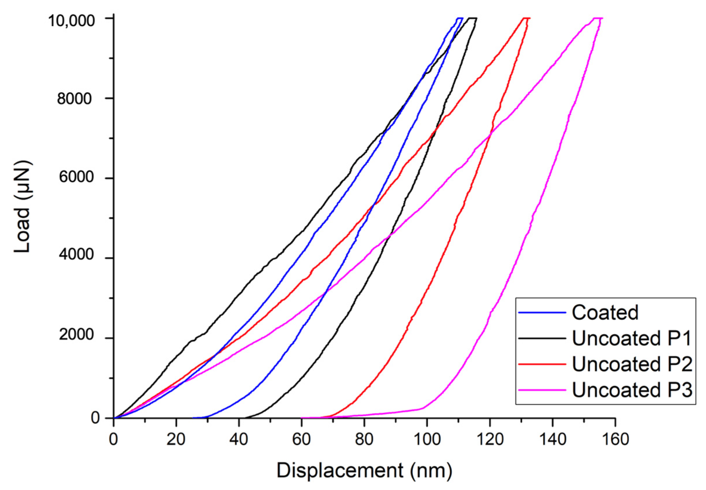
3.2. Surface and Mechanical Characterization
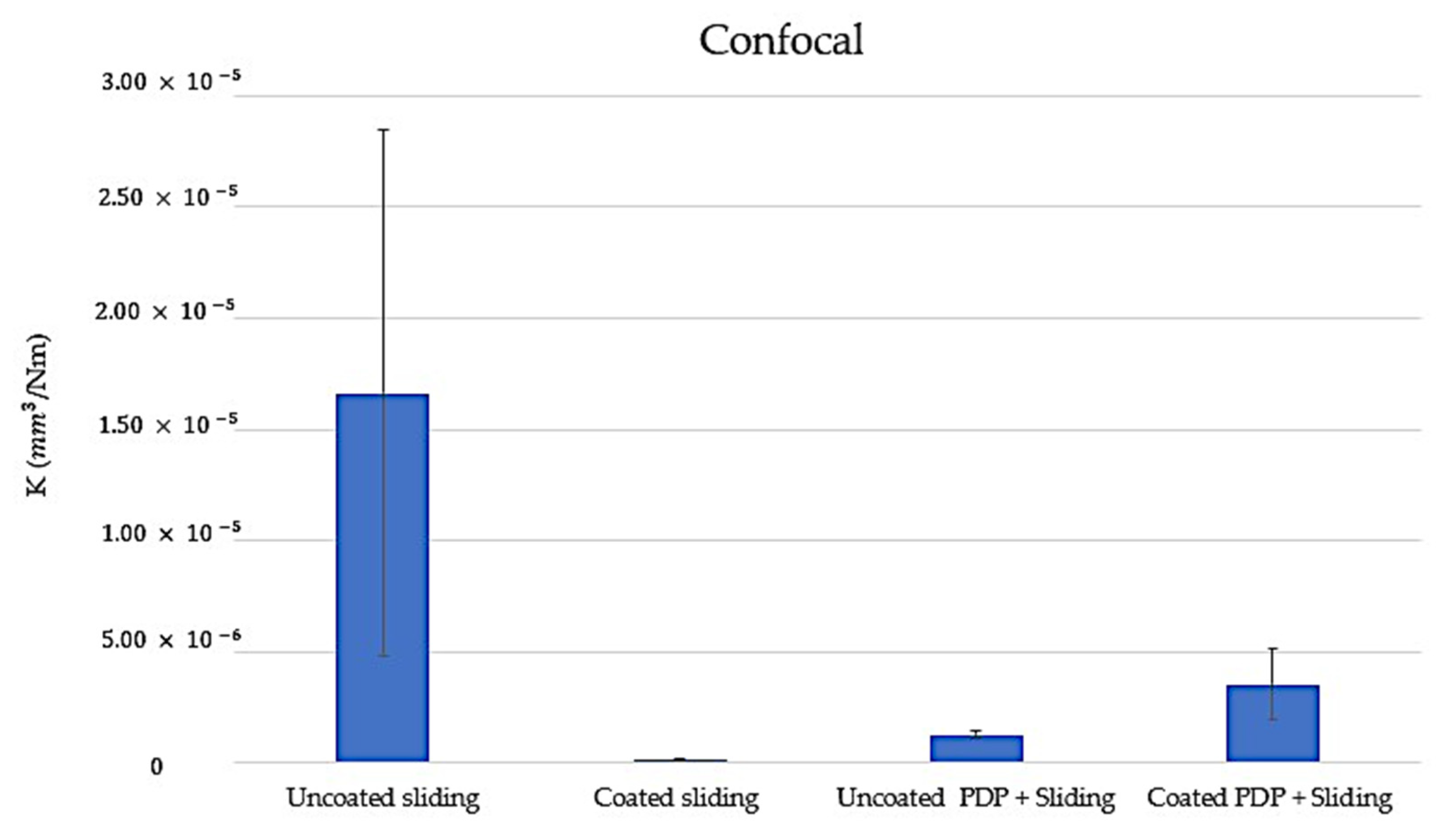
3.3. Corrosion and Tribocorrosion Tests
4. Discussion
5. Conclusions
Author Contributions
Funding
Institutional Review Board Statement
Informed Consent Statement
Data Availability Statement
Conflicts of Interest
References
- Bobzin, K. High-Performance Coatings for Cutting Tools. CIRP J. Manuf. Sci. Technol. 2017, 18, 1–9. [Google Scholar] [CrossRef]
- Chang, Y.Y.; Lai, H.M. Wear Behavior and Cutting Performance of CrAlSiN and TiAlSiN Hard Coatings on Cemented Carbide Cutting Tools for Ti Alloys. Surf. Coat. Technol. 2014, 259, 152–158. [Google Scholar] [CrossRef]
- Shieh, Y.N.; Chang, Y.Y. Influence of Cobalt Ion Implantation on Optical Properties of Titanium Dioxide Thin Films. Thin Solid Films 2010, 518, 7464–7467. [Google Scholar] [CrossRef]
- Thobor-Keck, A.; Lapostolle, F.; Dehlinger, A.S.; Pilloud, D.; Pierson, J.F.; Coddet, C. Influence of Silicon Addition on the Oxidation Resistance of CrN Coatings. Surf. Coat. Technol. 2005, 200, 264–268. [Google Scholar] [CrossRef]
- Chang, Y.Y.; Chang, C.P. High Temperature Stability of Multicomponent TiAISiN and CrAISiN Coatings. J. Nanosci. Nanotechnol. 2010, 10, 4762–4766. [Google Scholar] [CrossRef]
- Chang, Y.Y.; Cheng, C.M.; Liou, Y.Y.; Tillmann, W.; Hoffmann, F.; Sprute, T. High Temperature Wettability of Multicomponent CrAlSiN and TiAlSiN Coatings by Molten Glass. Surf. Coat. Technol. 2013, 231, 24–28. [Google Scholar] [CrossRef]
- Sun, S.Q.; Ye, Y.W.; Wang, Y.X.; Liu, M.Q.; Liu, X.; Li, J.L.; Wang, L.P. Structure and Tribological Performances of CrAlSiN Coatings with Different Si Percentages in Seawater. Tribol. Int. 2017, 115, 591–599. [Google Scholar] [CrossRef]
- Wu, W.; Chen, W.; Yang, S.; Lin, Y.; Zhang, S.; Cho, T.Y.; Lee, G.H.; Kwon, S.C. Design of AlCrSiN Multilayers and Nanocomposite Coating for HSS Cutting Tools. Appl. Surf. Sci. 2015, 351, 803–810. [Google Scholar] [CrossRef]
- Zhang, Y.F.; Yan, W.Q.; Chen, L.; Liao, B.; Hua, Q.S.; Zhang, X. A Hard yet Tough CrAlSiN Nanocomposite Coating for Blades Deposited by Filtered Cathode Vacuum Arc. Surf. Interfaces 2021, 25, 101156. [Google Scholar] [CrossRef]
- Chen, J.K.; Chang, C.L.; Shieh, Y.N.; Tsai, K.J.; Tsai, B.H. Structures and Properties of (TiAlSi)N Films. Procedia Eng. 2012, 36, 335–340. [Google Scholar] [CrossRef]
- Hu, J.; Zhang, J.; Jiang, Z.; Ding, X.; Zhang, Y.; Han, S.; Sun, J.; Lian, J. Plastic Deformation Behavior during Unloading in Compressive Cyclic Test of Nanocrystalline Copper. Mater. Sci. Eng. A 2016, 651, 999–1009. [Google Scholar] [CrossRef]
- Tao, H.; Tsai, M.T.; Chen, H.W.; Huang, J.C.; Duh, J.G. Improving High-Temperature Tribological Characteristics on Nanocomposite CrAlSiN Coating by Mo Doping. Surf. Coat. Technol. 2018, 349, 752–756. [Google Scholar] [CrossRef]
- Bilgin, S.; Güler, O.; Alver, Ü.; Erdemir, F.; Aslan, M.; Çanakçı, A. Effect of TiN, TiAlCN, AlCrN, and AlTiN Ceramic Coatings on Corrosion Behavior of Tungsten Carbide Tool. J. Aust. Ceram. Soc. 2021, 57, 263–273. [Google Scholar] [CrossRef]
- Chen, L.; Zhao, Y.; Meng, F.; Yu, T.; Ma, Z.; Qu, S.; Sun, Z. Effect of TiC Content on the Microstructure and Wear Performance of in Situ Synthesized Ni-Based Composite Coatings by Laser Direct Energy Deposition. Surf. Coat. Technol. 2022, 444, 128678. [Google Scholar] [CrossRef]
- Chen, L.; Yu, T.; Guan, C.; Zhao, Y. Microstructure and Properties of Metal Parts Remanufactured by Laser Cladding TiC and TiB2 Reinforced Fe-Based Coatings. Ceram. Int. 2022, 48, 14127–14140. [Google Scholar] [CrossRef]
- Zhao, Y.; Yu, T.; Sun, J.; Jiang, S. Microstructure and Properties of Laser Cladded B4C/TiC/Ni-Based Composite Coating. Int. J. Refract. Metals Hard Mater. 2020, 86, 105112. [Google Scholar] [CrossRef]
- Mosquera, A.; Mera, L.; Fox-Rabinovich, G.S.; Martínez, R.; Azkona, I.; Endrino, J.L. Advantages of Nanoimpact Fracture Testing in Studying the Mechanical Behavior of Cral(Si)n Coatings. Nanosci. Nanotechnol. Lett. 2010, 2, 352–356. [Google Scholar] [CrossRef]
- PLATIT. Advanced Coating Systems Nanostructured Coatings for High Per-Formance Tools. Reprint Werkzeug Tech. 2003, 77, 2–7. [Google Scholar]
- Oliver, W.C.; Pharr, G.M. An Improved Technique for Determining Hardness and Elastic Modulus Using Load and Displacement Sensing Indentation Experiments. J. Mater. Res. 2011, 7, 1564–1583. [Google Scholar] [CrossRef]
- Bec, S.; Tonck, A.; Loubet, J.L. A Simple Guide to Determine Elastic Properties of Films on Substrate from Nanoindentation Experiments. Philos. Mag. 2006, 86, 5347–5358. [Google Scholar] [CrossRef] [Green Version]
- Sneddon, I.N. The Relation between Load and Penetration in the Axisymmetric Boussinesq Problem for a Punch of Arbitrary Profile. Int. J. Eng. Sci. 1965, 3, 47–57. [Google Scholar] [CrossRef]
- Zhang, L.; Chen, Y.; Wan, Q.L.; Liu, T.; Zhu, J.F.; Tian, W. Electrochemical Corrosion Behaviors of Straight WC–Co Alloys: Exclusive Variation in Grain Sizes and Aggressive Media. Int. J. Refract. Met. Hard Mater. 2016, 57, 70–77. [Google Scholar] [CrossRef]
- Ardila Téllez, L.C. Nuevos Recubrimientos Basados En Nitruros Con Adiciones de Silicio Para El Mecanizado de La Aleación Inconel 718 Con Herramientas de Metal Duro. Ph.D. Thesis, Universidad de Navarra, Pamplona, Spain, 2010. [Google Scholar]
- Takadoum, J.; Houmid Bennani, H. Influence of Substrate Roughness and Coating Thickness on Adhesion, Friction and Wear of TiN Films. Surf. Coat. Technol. 1997, 96, 272–282. [Google Scholar] [CrossRef]
- Croll, S.G. Surface Roughness Profile and Its Effect on Coating Adhesion and Corrosion Protection: A Review. Prog. Org. Coat. 2020, 148, 105847. [Google Scholar] [CrossRef]
- Ghosh, G.; Sidpara, A.; Bandyopadhyay, P.P. Understanding the Role of Surface Roughness on the Tribological Performance and Corrosion Resistance of WC-Co Coating. Surf. Coat. Technol. 2019, 378, 125080. [Google Scholar] [CrossRef]
- Leyland, A.; Matthews, A. On the Significance of the H/E Ratio in Wear Control: A Nanocomposite Coating Approach to Optimised Tribological Behaviour. Wear 2000, 246, 1–11. [Google Scholar] [CrossRef]
- Charitidis, C.A. Nanomechanical and Nanotribological Properties of Carbon-Based Thin Films: A Review. Int. J. Refract. Met. Hard Mater. 2010, 28, 51–70. [Google Scholar] [CrossRef]
- Charitidis, C.; Logothetidis, S.; Douka, P. Nanoindentation and Nanoscratching Studies of Amorphous Carbon Films. Diam. Relat. Mater. 1999, 8, 558–562. [Google Scholar] [CrossRef]
- le Bourhis, E. Indentation Mechanics and Its Application to Thin Film Characterization. Vacuum 2008, 82, 1353–1359. [Google Scholar] [CrossRef]
- Czyzniewski, A. Optimising Deposition Parameters of W-DLC Coatings for Tool Materials of High Speed Steel and Cemented Carbide. Vacuum 2012, 86, 2140–2147. [Google Scholar] [CrossRef]
- Sun, W.; Li, M.; Wu, M.; Hu, J. Uniformity of Si-Containing Diamond-like Carbon Films Deposited at Different Positions by Mesh Hollow Cathode Discharge. Results Phys. 2019, 14, 102480. [Google Scholar] [CrossRef]
- Wang, L.; Li, L.; Kuang, X. Effect of Substrate Bias on Microstructure and Mechanical Properties of WC-DLC Coatings Deposited by HiPIMS. Surf. Coat. Technol. 2018, 352, 33–41. [Google Scholar] [CrossRef]
- Galvan, D.; Pei, Y.T.; de Hosson, J.T.M. Deformation and Failure Mechanism of Nano-Composite Coatings under Nano-Indentation. Surf. Coat. Technol. 2006, 200, 6718–6726. [Google Scholar] [CrossRef] [Green Version]
- Hanner, L.A.; Pittari, J.J.; Swab, J.J. Dynamic Hardness of Cemented Tungsten Carbides. Int. J. Refract. Met. Hard Mater. 2018, 75, 294–298. [Google Scholar] [CrossRef]
- Ciurans-Oset, M.; Mundó-Tijeras, I.; Mouzon, J.; Akhtar, F. Use of AFM Topography Images to Determine Microindentation Hardness of Cast Tungsten Carbide Powders. Int. J. Refract. Met. Hard Mater. 2022, 107, 105878. [Google Scholar] [CrossRef]
- Srivatsan, T.S.; Woods, R.; Petraroli, M.; Sudarshan, T.S. An Investigation of the Influence of Powder Particle Size on Microstructure and Hardness of Bulk Samples of Tungsten Carbide. Powder Technol. 2002, 122, 54–60. [Google Scholar] [CrossRef]
- Gao, Y.; Cai, F.; Lu, X.; Xu, W.; Zhang, C.; Zhang, J.; Qu, X. Design of Cycle Structure on Microstructure, Mechanical Properties and Tribology Behavior of AlCrN/AlCrSiN Coatings. Ceram. Int. 2022, 48, 12255–12270. [Google Scholar] [CrossRef]
- Çam, A.S.; Ergüder, T.O.; Kaya, G.; Yıldız, F. Improvement of Structural/Tribological Properties and Milling Performances of Tungsten Carbide Cutting Tools by Bilayer TiAlN/TiSiN and Monolayer AlCrSiN Ceramic Films. Ceram. Int. 2022, 48, 26342–26350. [Google Scholar] [CrossRef]
- Wu, Z.; Huan, J.; Geng, D.; Ye, R.; Wang, Q. Investigation on Plastic Deformation of Arc-Evaporated AlCrSiN and AlCrSiON Nanocomposite Films by Indentation. Surf. Coat. Technol. 2022, 441, 128570. [Google Scholar] [CrossRef]
- Ziemath, E.C.; Herrmann, P.S.P. Densification and Residual Stresses Induced in Glass Surfaces by Vickers Indentations. J. Non Cryst. Solids 2000, 273, 19–24. [Google Scholar] [CrossRef]
- Ashby, M.F.; Jones, D.R.H.; David, R.H. Engineering Materials: An Introduction to Their Properties and Applications; Pergamon Press: Oxford, NY, USA, 1980; p. 278. [Google Scholar]
- Zhang, S.; Wang, L.; Wang, Q.; Li, M. A Superhard CrAlSiN Superlattice Coating Deposited by a Multi-Arc Ion Plating: II. Thermal Stability and Oxidation Resistance. Surf. Coat. Technol. 2013, 214, 153–159. [Google Scholar] [CrossRef]
- Ćorić, D.; Šnajdar Musa, M.; Sakoman, M.; Alar, Ž. Analysis of Different Complex Multilayer PACVD Coatings on Nanostructured WC-Co Cemented Carbide. Coatings 2021, 11, 823. [Google Scholar] [CrossRef]
- Claver, A.; Jiménez-Piqué, E.; Palacio, J.F.; Almandoz, E.; de Ara, J.F.; Fernández, I.; Santiago, J.A.; Barba, E.; García, J.A. Comparative Study of Tribomechanical Properties of HiPIMS with Positive Pulses DLC Coatings on Different Tools Steels. Coatings 2021, 11, 28. [Google Scholar] [CrossRef]
- Su, Q.; Zhu, S.; Ding, H.; Bai, Y.; Di, P. Comparison of the Wear Behaviors of Advanced and Conventional Cemented Tungsten Carbides. Int. J. Refract. Met. Hard Mater. 2019, 79, 18–22. [Google Scholar] [CrossRef]
- Doñu-Ruiz, M.A.; López-Perrusquia, N.; Renteria-Salcedo, A.; Flores-Martinez, M.; Rodriguez-De Anda, E.; Muhl, S.; Hernández-Navarro, C.; García, E. Tribocorrosion Behavior of Boride Coating on CoCrMo Alloy Produced by Thermochemical Process in 0.35% NaCl Solution. Surf. Coat. Technol. 2021, 425, 127698. [Google Scholar] [CrossRef]
- Cao, S.; Mischler, S. A Lubricated Tribocorrosion Model Incorporating Surface Roughness. Biotribology 2021, 26, 100181. [Google Scholar] [CrossRef]
- Hu, K.; Liu, X.; Zhang, S.; Xue, Z.; Yang, Y.; Yang, K. Tribocorrosion Behavior of HVOF Sprayed WC-Based Cermet Coatings in Sodium Chloride Solution Environment in Relation to Binder Phases. Surf. Coat. Technol. 2022, 435, 128248. [Google Scholar] [CrossRef]
- Zhang, M.; Zhou, F.; Wang, Q.; Fu, Y.; Zhou, Z. Tribocorrosion Characteristics of CrMoSiCN/Ag Coatings on Ti6Al4V Alloys in Seawater. Ceram. Int. 2021, 47, 31780–31797. [Google Scholar] [CrossRef]
- Boukantar, A.R.; Djerdjare, B.; Guiberteau, F.; Ortiz, A.L. A Critical Comparison of the Tribocorrosive Performance in Highly-Alkaline Wet Medium of Ultrafine-Grained WC Cemented Carbides with Co, Co+Ni, or Co+Ni+Cr Binders. Int. J. Refract. Met. Hard Mater. 2021, 95, 105452. [Google Scholar] [CrossRef]
- Ouyang, Y.; Chen, Z.; Jiang, C.; Yang, W.; Chen, Y.; Yin, X.; Liu, Y. Design of the Double-Layer Biocompatible Coating on AZ31 Magnesium Alloy for Highly Effective Corrosion Resistance. Surf. Coat. Technol. 2021, 428, 127897. [Google Scholar] [CrossRef]
- Sutthiruangwong, S.; Mori, G. Corrosion Properties of Co-Based Cemented Carbides in Acidic Solutions. Int. J. Refract. Met. Hard Mater. 2003, 21, 135–145. [Google Scholar] [CrossRef]


| Anchoring layer | 0.25 μm |
| Transition layer + outer layer | 4.25 μm |
| Total thickness | 4.5 μm |
| Sample | Hardness (Gpa) | Young’s Modulus (Gpa) | H/E | |
|---|---|---|---|---|
| Coated sample | 34.1 ± 6.6 | 301 ± 35 | 0.113 | 0.438 |
| Uncoated P1 (TiC) | 26.4 ± 2.5 | 310 ± 8.5 | 0.085 | 0.191 |
| Uncoated P2 (WC) | 19.6 ± 1.8 | 302 ± 14.8 | 0.064 | 0.082 |
| Uncoated P3 (WC′) | 13.8 ± 1.0 | 270 ± 2.2 | 0.051 | 0.036 |
| Critical Load | Value |
|---|---|
| Lc2 | 33.3 ± 1.5 N |
| Lc3 | 63.7 ± 4.9 N |
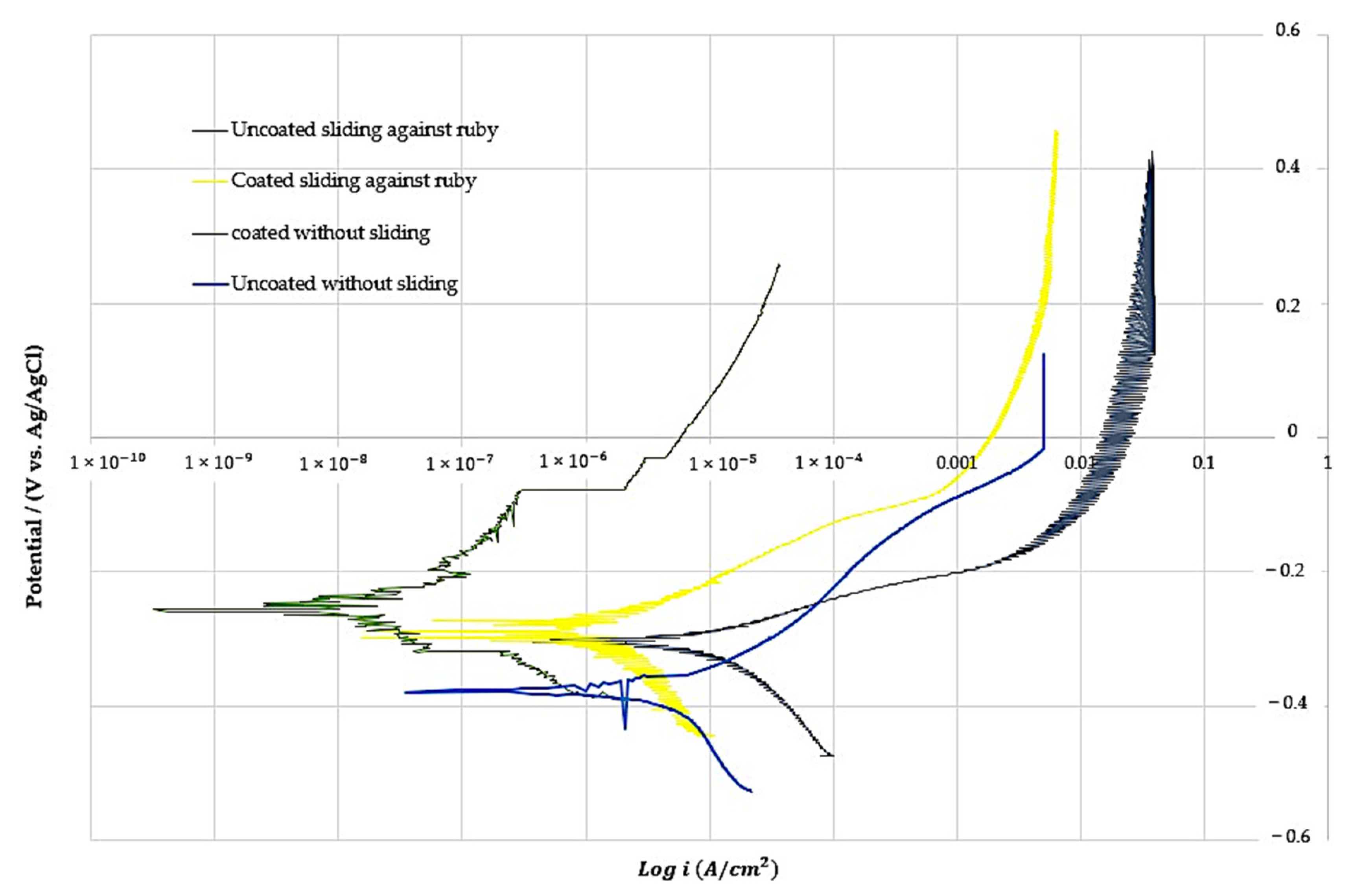
| Sample | Corrosion Potential (V) | Current Density (μA/cm2) |
|---|---|---|
| Uncoated without sliding | −0.38 | 1.11 |
| Coated without sliding | −0.26 | 0.03 |
| Uncoated sliding against ruby | −0.31 | 8.56 |
| Coated sliding against ruby | −0.29 | 0.36 |
Publisher’s Note: MDPI stays neutral with regard to jurisdictional claims in published maps and institutional affiliations. |
© 2022 by the authors. Licensee MDPI, Basel, Switzerland. This article is an open access article distributed under the terms and conditions of the Creative Commons Attribution (CC BY) license (https://creativecommons.org/licenses/by/4.0/).
Share and Cite
García, J.A.; Claver, A.; Marques, M.; Almandoz, E.; Fernández de Ara, J.; Palacio, J.F.; Azkona, I. Improvement of the Tribocorrosion Properties of Cemented Carbide (WC-Tic-Co) Samples with PVD Coating. Coatings 2022, 12, 1884. https://doi.org/10.3390/coatings12121884
García JA, Claver A, Marques M, Almandoz E, Fernández de Ara J, Palacio JF, Azkona I. Improvement of the Tribocorrosion Properties of Cemented Carbide (WC-Tic-Co) Samples with PVD Coating. Coatings. 2022; 12(12):1884. https://doi.org/10.3390/coatings12121884
Chicago/Turabian StyleGarcía, José Antonio, Adrián Claver, Mikel Marques, Eluxka Almandoz, Jonathan Fernández de Ara, José F. Palacio, and Ibon Azkona. 2022. "Improvement of the Tribocorrosion Properties of Cemented Carbide (WC-Tic-Co) Samples with PVD Coating" Coatings 12, no. 12: 1884. https://doi.org/10.3390/coatings12121884