
Dimensionless Analysis to Determine Elastoplastic Properties of Thin Films by Indentation

Abstract
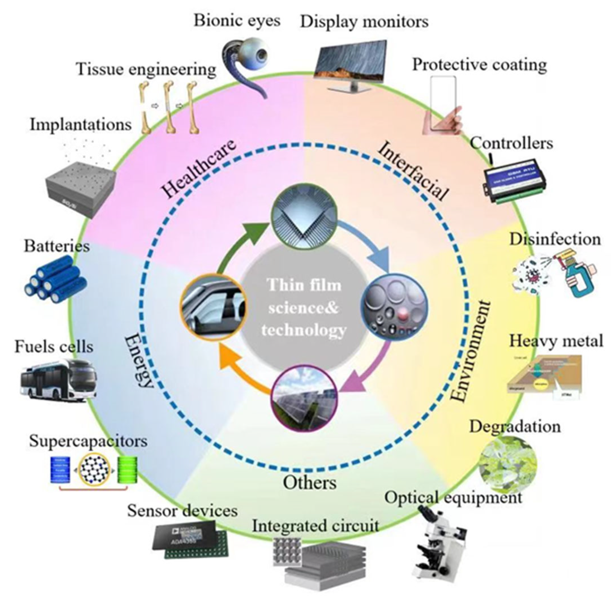
:1. Introduction
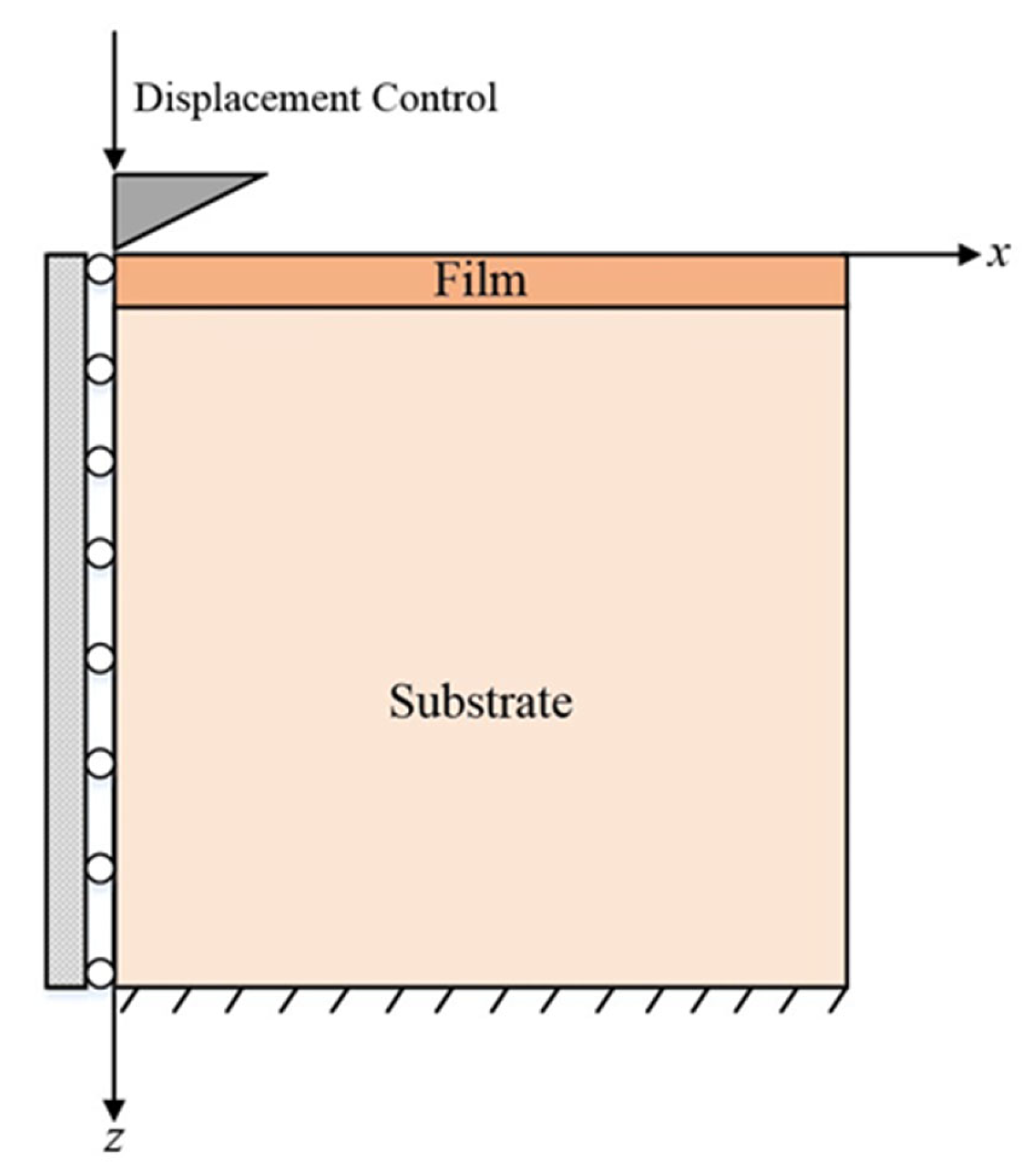
2. Indentation Simulation by FE Method
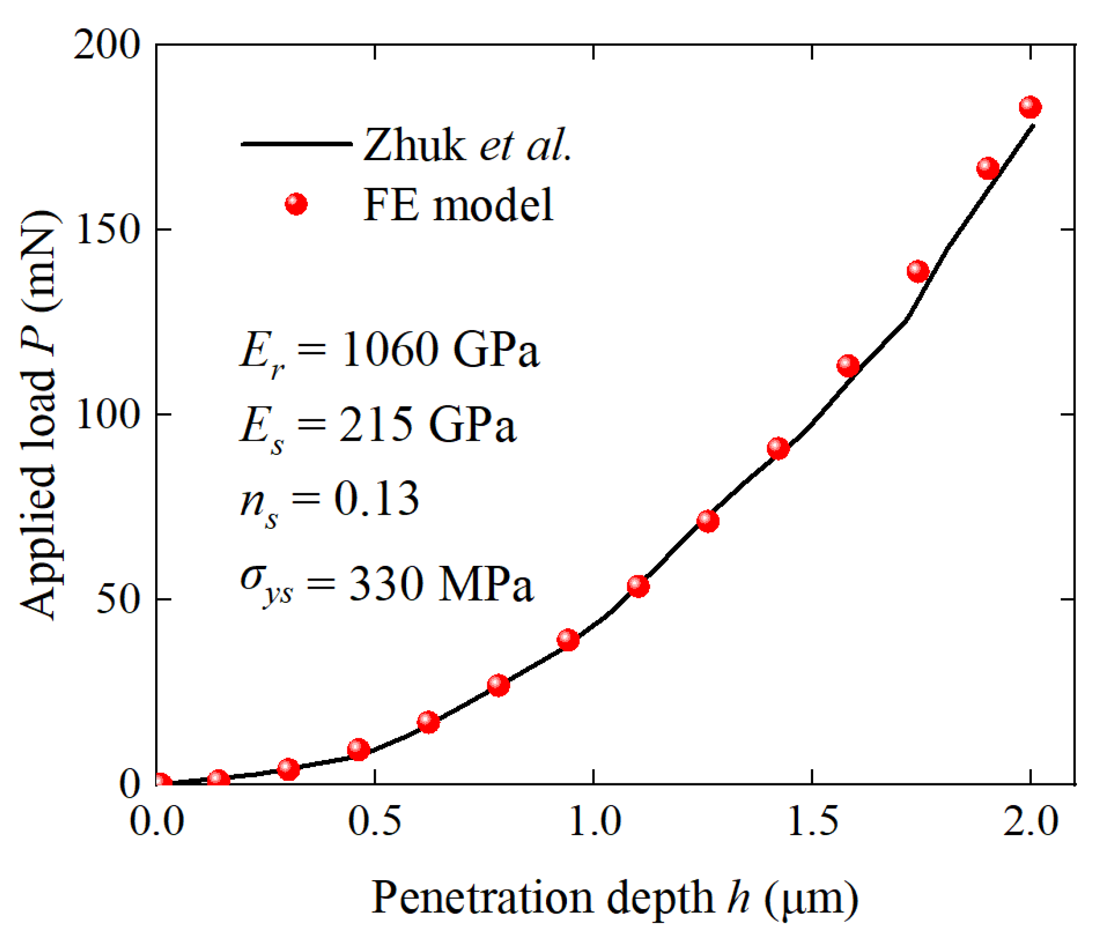
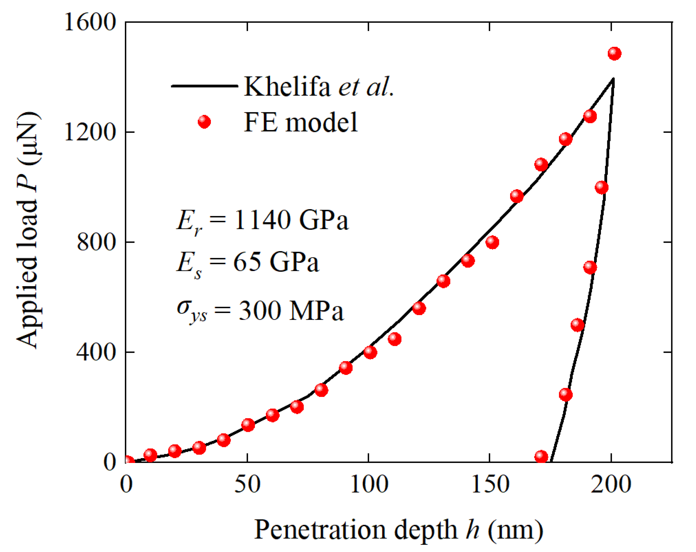
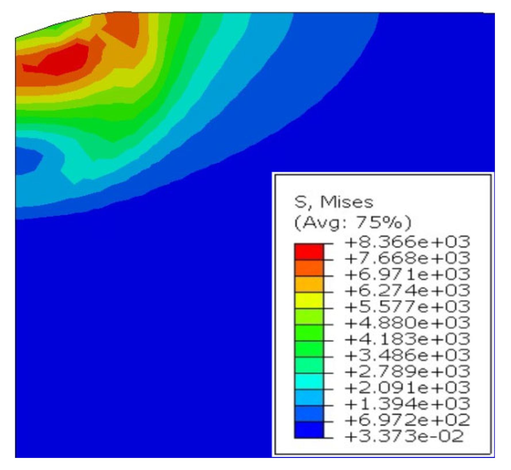
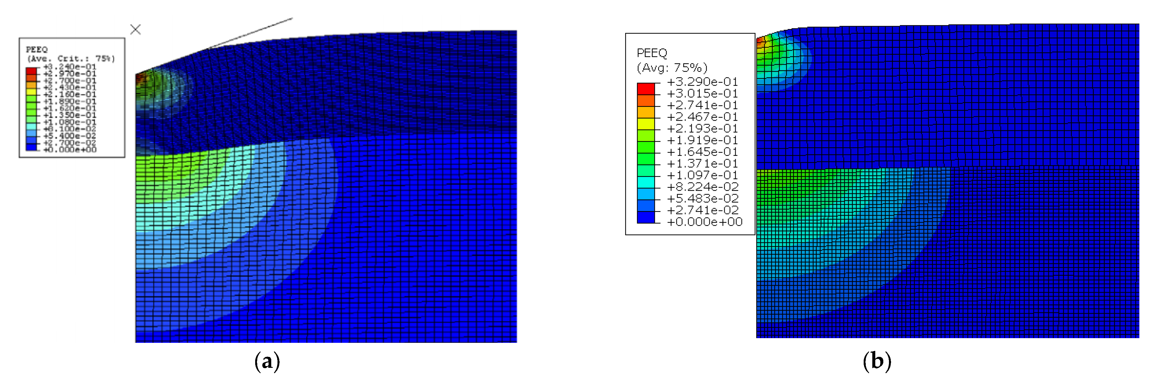
2.1. Validation with No-Film Model
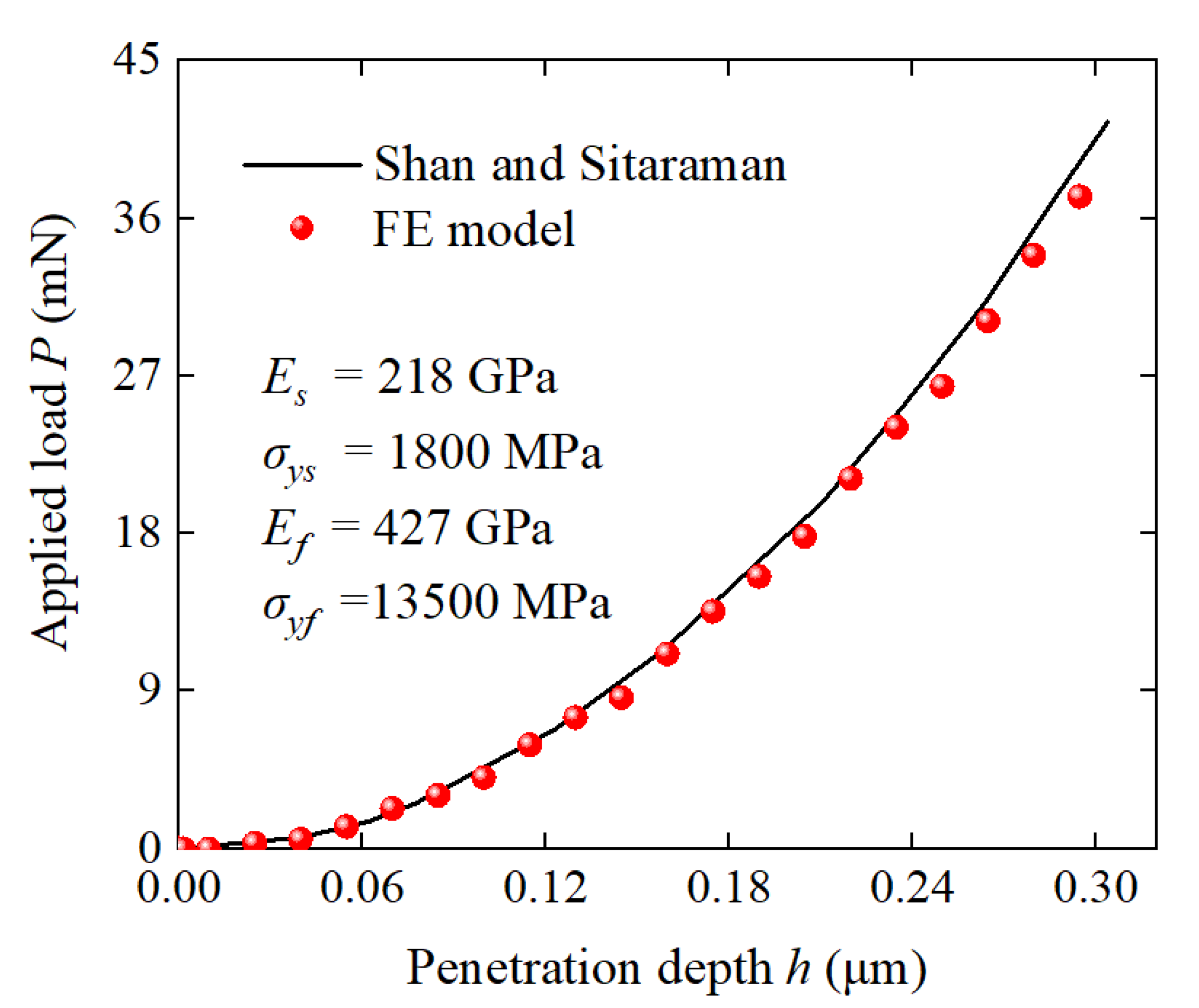
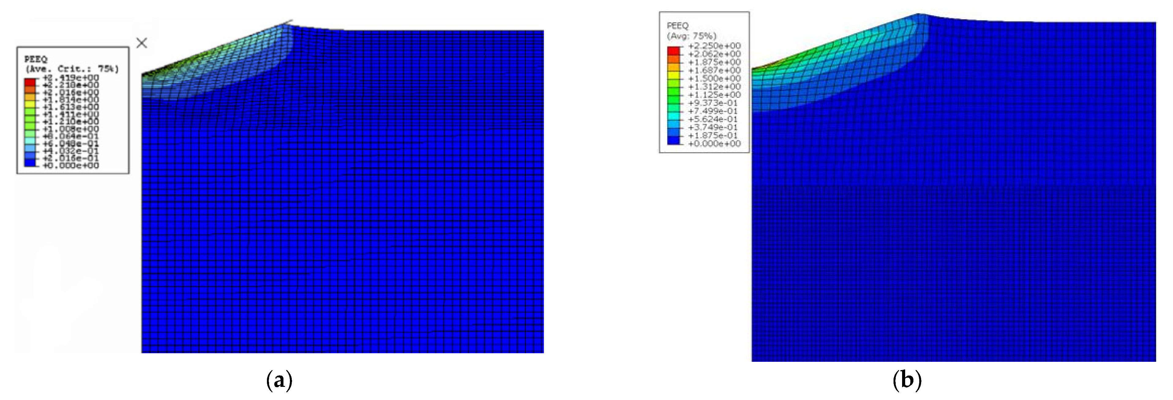
2.2. Validation with Film/Substrate Model
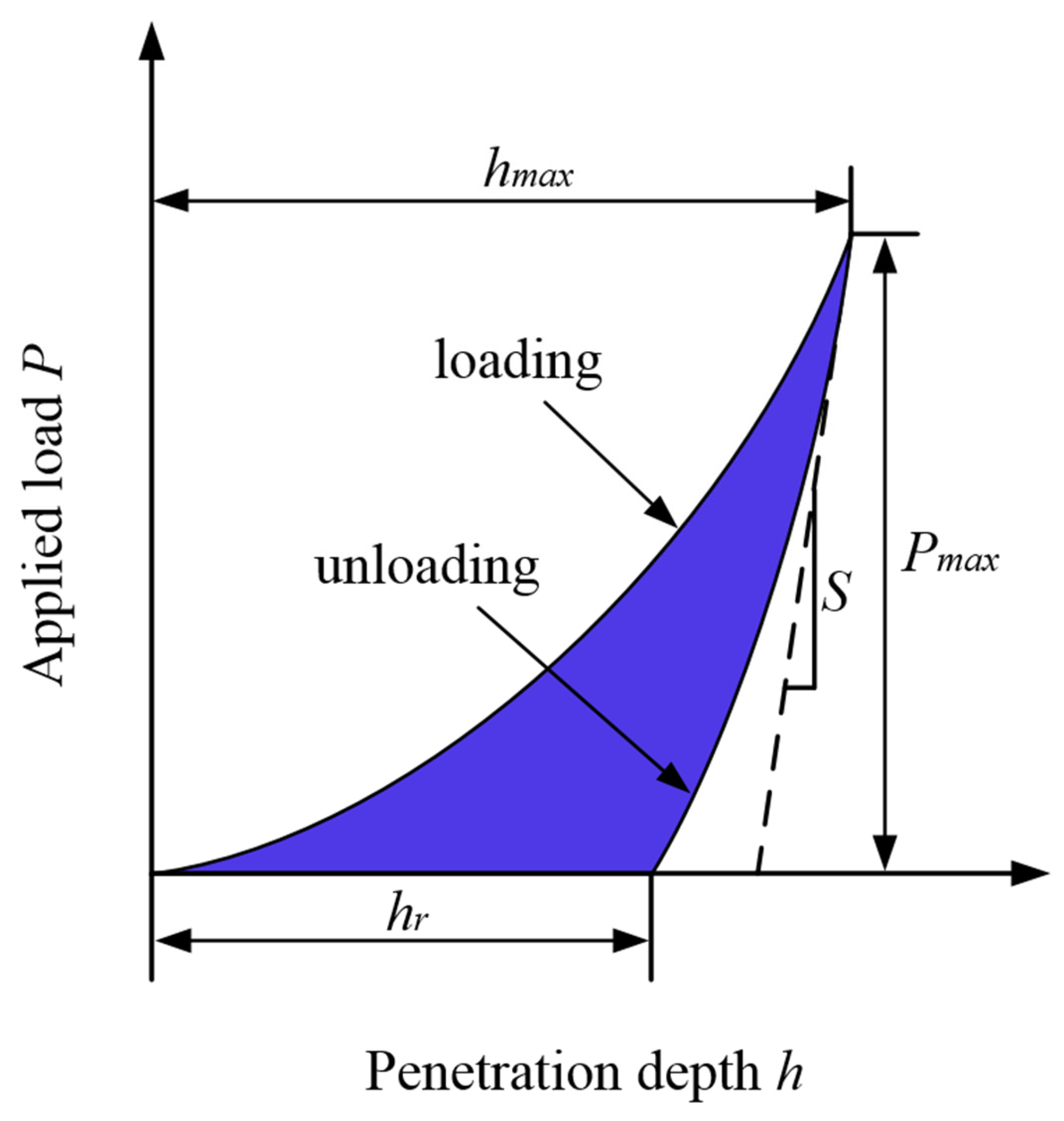
3. Dimensionless Analysis
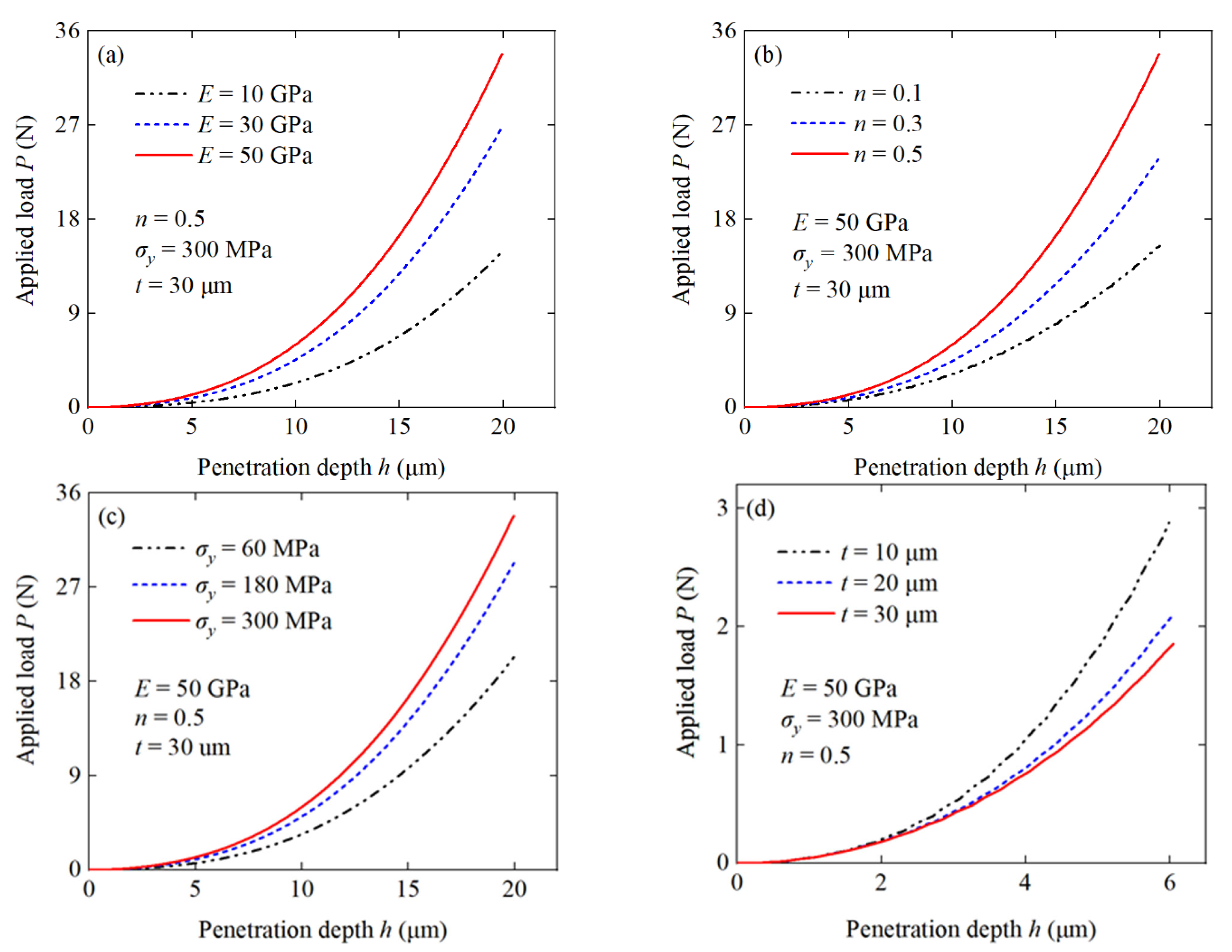
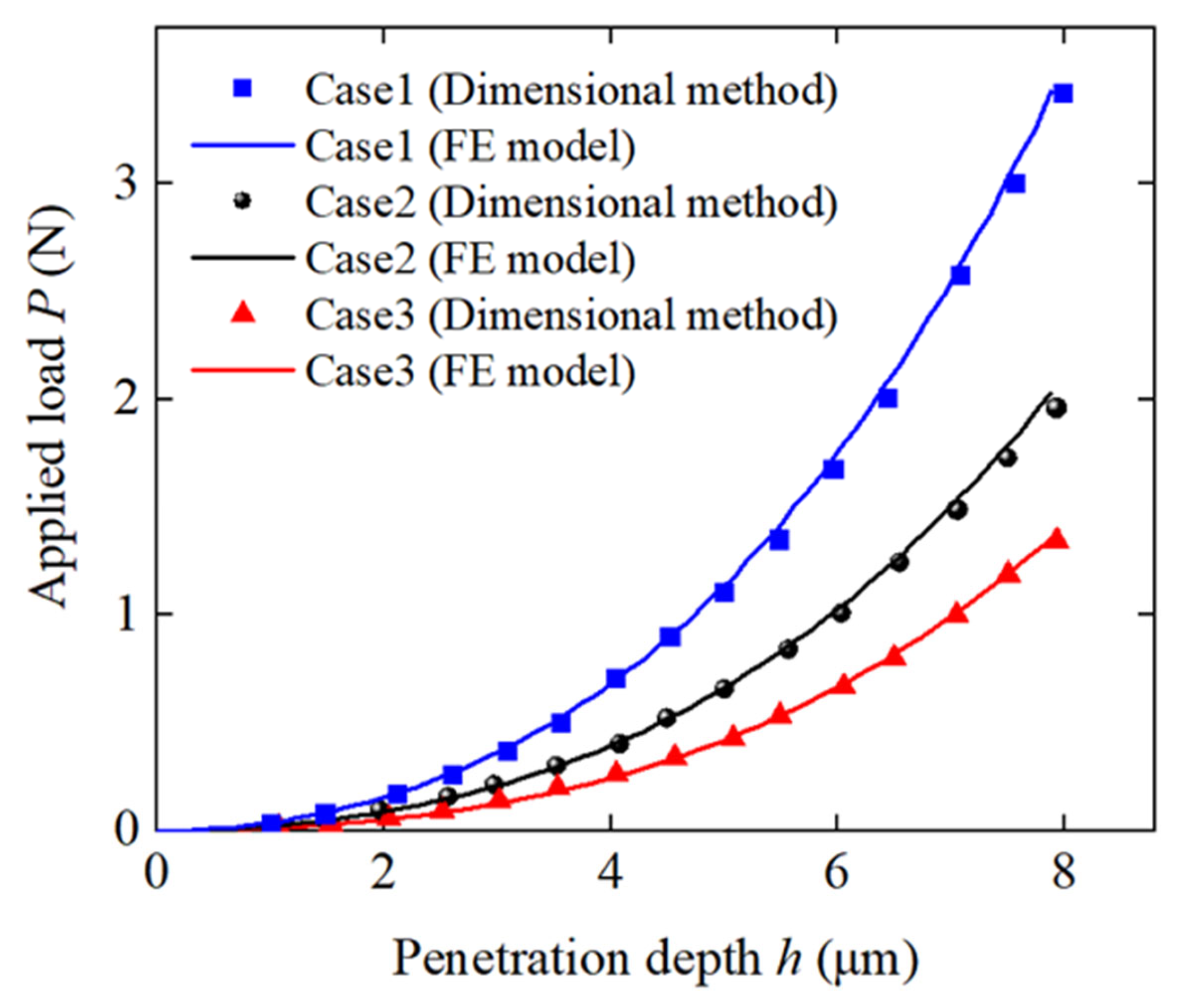
4. Results and Discussions
5. Conclusions
Author Contributions
Funding
Institutional Review Board Statement
Informed Consent Statement
Data Availability Statement
Conflicts of Interest
References
- Lin, K.L.; Chang, W.K.; Chang, T.C.; Lee, C.H.; Lin, C.H. Recycling thin film transistor liquid crystal display (TFT-LCD) waste glass produced as glass-ceramics. J. Clean Prod. 2009, 17, 1499–1503. [Google Scholar] [CrossRef]
- Nagamura, T.; Tanaka, K. Physical properties of polymer thin Films for device application. IETE Tech. Rev. 2009, 109, 1–2. [Google Scholar]
- Gizatulin, A.R.; Sultanov, A.K. Application of whispering gallery modes (WGM) in optical communications. Opt. Commun. 2017, 10774, 545–555. [Google Scholar]
- Cordill, M.J.; Bahr, D.F.; Moody, N.R.; Gerberich, W.W. Recent developments in thin film adhesion measurement by laser-induced stress waves. J. Exp. Med. 2007, 22, 249–257. [Google Scholar]
- Ouyang, J. Applications of carbon nanotubes and graphene for third-generation solar cells and fuel cells. Nano Mater. Sci. 2019, 1, 77–90. [Google Scholar] [CrossRef]
- Prokhorov, A.M.; Smolenskiĭ, G.A.; Ageev, A.N. Optical phenomena in thin-film magnetic waveguides and their technical application. Sov. Phys. Uspekhi 1984, 27, 339. [Google Scholar] [CrossRef]
- Islam, M.M.; Shakil, S.I.; Shaheen, N.M.; Bayati, P.; Haghshenas, M. An overview of microscale indentation fatigue: Composites, thin films, coatings, and ceramics. Micron 2021, 148, 103110. [Google Scholar] [CrossRef]
- Zhou, Y.; Lin, X.G.; Wang, Y.; Liu, G.Q.; Zhu, X.Y.; Huang, Y.K.; Guo, Y.C.; Gao, C.; Zhou, M. Study on gas sensing of reduced graphene oxide/ZnO thin film at room temperature. Sens. Actuators B Chem. 2017, 240, 870–880. [Google Scholar] [CrossRef]
- Bhushan, B.; Li, X.D. Nanomechanical characterisation of solid surfaces and thin films. Int. Mater. Rev. 2003, 48, 125–164. [Google Scholar] [CrossRef]
- Oliver, W.C.; Pharr, G.M. An improved technique for determining hardness and elastic modulus using load and displacement sensing indentation experiments. J. Mater. Res. 1992, 7, 1564–1583. [Google Scholar] [CrossRef]
- He, D.; Zhu, J.C.; Lai, Z.H.; Liu, Y.; Yang, X.W.; Nong, Z.S. Residual elastic stress-strain field and geometrically necessary dislocation density distribution around nano-indentation in TA15 titanium alloy. Trans. Nonferrous Met. Soc. China 2013, 23, 7–13. [Google Scholar] [CrossRef]
- Oliver, W.C.; Pharr, G.M. Measurement of hardness and elastic modulus by instrumented indentation: Advances in understanding and refinements to methodology. J. Mater. Res. 2004, 19, 3–20. [Google Scholar] [CrossRef]
- Bouzakis, K.D.; Michailidis, N.; Hadjiyiannis, S.; Skordaris, G.; Erkens, G. The effect of specimen roughness and indenter tip geometry on the determination accuracy of thin hard coatings stress-strain laws by nanoindentation. Mater. Charact. 2002, 49, 149–156. [Google Scholar] [CrossRef]
- Rauchs, G.; Bardon, J. Identification of elasto-viscoplastic material parameters by indentation testing and combined finite element modelling and numerical optimization. Finite Elem. Anal. Des. 2011, 47, 653–667. [Google Scholar] [CrossRef]
- Shelef, Y.; Bar-On, B. Size effects on the dynamic indentation modulus of films. Mech. Mater. 2022, 164, 104118. [Google Scholar] [CrossRef]
- Kampouris, A.K.; Lappas, K.I.; Konstantinidis, A.A.; Aifantis, E.C. A new method for interpreting Vickers indentation measurements. Mater. Today 2022, 67, 964–970. [Google Scholar] [CrossRef]
- Chollacoop, N.; Dao, M.; Suresh, S. Depth-sensing instrumented indentation with dual sharp indenters. Acta Mater. 2003, 51, 3713–3729. [Google Scholar] [CrossRef]
- Treier, K.; Lester, P.; Hubbuch, J. Application of genetic algorithms and response surface analysis for the optimization of batch chromatographic systems. Biochem. Eng. J. 2012, 63, 66–75. [Google Scholar] [CrossRef]
- Kim, J.Y.; Kang, S.K.; Lee, J.J.; Jang, J.I.; Lee, Y.H.; Kwon, D. Influence of surface-roughness on indentation size effect. Acta Mater. 2007, 55, 3555–3562. [Google Scholar] [CrossRef]
- Argatov, I.I.; Sabina, F.J. Small-scale indentation of an elastic coated half-space: Influence of Poisson’s ratios on the substrate effect. Int. J. Eng. Sci. 2014, 81, 33–40. [Google Scholar] [CrossRef]
- Long, X.; Zhang, X.D.; Tang, W.B.; Wang, S.B.; Feng, Y.H.; Chang, C. Micromachines calibration of a constitutive model from tension and nanoindentation for lead-free solder. Micromachines 2019, 9, 608. [Google Scholar] [CrossRef] [PubMed] [Green Version]
- Long, X.; Wang, S.B.; Feng, Y.H.; Yao, Y.; Keer, L.M. Annealing effect on residual stress of Sn-3.0Ag-0.5Cu solder measured by nanoindentation and constitutive experiments. Mat. Sci. Eng. 2017, 696, 90–95. [Google Scholar] [CrossRef] [Green Version]
- Long, X.; Wang, S.B.; He, X.; Yao, Y. Annealing optimization for tin-lead eutectic solder by constitutive experiment and simulation. J. Mater. Res. 2017, 32, 3089–3099. [Google Scholar] [CrossRef]
- Long, X.; Feng, Y.H.; Yao, Y. Cooling and annealing effect on indentation response of lead-free solder. Int. J. Appl. Mech. 2017, 9, 1750057. [Google Scholar] [CrossRef] [Green Version]
- Long, X.; Shen, Z.Y.; Jia, Q.P.; Li, J.; Dong, R.-P.; Su, Y.-T.; Yang, X.; Zhou, K. Determine the unique constitutive properties of elastoplastic materials from their plastic zone evolution under nanoindentation. Mech. Mater. 2022, 175, 104485. [Google Scholar] [CrossRef]
- Long, X.; Shen, Z.Y.; Lu, C.H.; Jia, Q.P.; Guan, C.; Chen, C.T.; Wang, H.D.; Li, Y. Reverse analysis of surface strain in elasto-plastic materials by nanoindentation. Int. J. Appl. Mech. 2021, 13, 2150106. [Google Scholar] [CrossRef]
- Chen, H.; Cai, L.X. Theoretical model for predicting uniaxial stress-strain relation by dual conical indentation based on equivalent energy principle. Acta Mater. 2016, 121, 181–189. [Google Scholar] [CrossRef]
- Hosseinzadeh, A.R.; Mahmoudi, A.H. Determination of mechanical properties using sharp macro-indentation method and genetic algorithm. Mech. Mater. 2017, 114, 57–68. [Google Scholar] [CrossRef]
- Hyun, H.C.; Kim, M.; Lee, J.H.; Lee, H. A dual conical indentation technique based on FEA solutions for property evaluation. Mech. Mater. 2011, 43, 313–331. [Google Scholar] [CrossRef]
- Campbell, J.E.; Thompson, R.P.; Dean, J.; Clyne, T.W. Experimental and computational issues for automated extraction of plasticity parameters from spherical indentation. Mech. Mater. 2018, 124, 118–131. [Google Scholar] [CrossRef]
- Li, Y.G.; Kanouté, P.; Francois, M.; Chen, D.; Wang, H.W. Inverse identification of constitutive parameters with instrumented indentation test considering the normalized loading and unloading P-h curves. Int. J. Solids Struct. 2019, 156, 163–178. [Google Scholar] [CrossRef]
- Cheng, Y.T.; Cheng, C.M. Scaling approach to conical indentation in elastic-plastic solids with work hardening. J. Appl. Phys. 1998, 84, 1284–1291. [Google Scholar] [CrossRef]
- Dao, M.; Chollacoop, N.; Vliet, K.; Venkatesh, T.A.; Suresh, S.J.A.M. Computational modeling of the forward and reverse problems in instrumented sharp indentation. Acta Mater. 2001, 49, 3899–3918. [Google Scholar] [CrossRef]
- Zhuk, D.I.; Isaenkova, M.G.; Perlovich, Y.A.; Krymskaya, O.A. Finite element simulation of microindentation. Russ. Metally 2017, 2017, 390–396. [Google Scholar] [CrossRef]
- Khelifa, M.; Fierro, V.; Celzard, A. Finite element simulation of nanoindentation tests using a macroscopic computational model. J. Mech. Sci. Technol. 2014, 28, 3209–3217. [Google Scholar] [CrossRef]
- Shan, Z.; Sitaraman, S.K. Elastic-plastic characterization of thin films using nanoindentation technique. Thin Solid Films 2003, 437, 176–181. [Google Scholar] [CrossRef]
- Pelegri, A.A.; Huang, X. Nanoindentation on soft film/hard substrate and hard film/soft substrate material systems with finite element analysis. Compos. Sci. Technol. 2008, 68, 147–155. [Google Scholar] [CrossRef]
- Lichinchi, M.; Lenardi, C.; Haupt, J.; Vitali, R. Simulation of Berkovich nanoindentation experiments on thin films using finite element method. Thin Solid Films 1998, 333, 240–248. [Google Scholar] [CrossRef] [Green Version]
- Long, X.; Jia, Q.P.; Li, Z.; Wen, S.X. Reverse analysis of constitutive properties of sintered silver particles from nanoindentations. Int. J. Solids Struct. 2020, 191, 351–362. [Google Scholar] [CrossRef]
- Long, X.; Hu, B.; Feng, Y.H.; Chang, C.; Li, M.Y. Correlation of microstructure and constitutive behaviour of sintered silver particles via nanoindentation. Int. J. Mech. Sci. 2019, 161, 105020. [Google Scholar] [CrossRef]


| - | E (GPa) | ν | n | (Mpa) |
|---|---|---|---|---|
| Berkovich indenter | 1060 | 0.07 | - | - |
| Substrate | 215 | 0.28 | 0.13 | 330 |
| - | E (MPa) | n | (Mpa) | t (μm) |
|---|---|---|---|---|
| Case1 | 41,905.8 | 0.48 | 252.5 | 24 |
| Case2 | 20,251.6 | 0.40 | 225.7 | 20 |
| Case3 | 31,448.7 | 0.19 | 112.4 | 13 |
Publisher’s Note: MDPI stays neutral with regard to jurisdictional claims in published maps and institutional affiliations. |
© 2022 by the authors. Licensee MDPI, Basel, Switzerland. This article is an open access article distributed under the terms and conditions of the Creative Commons Attribution (CC BY) license (https://creativecommons.org/licenses/by/4.0/).
Share and Cite
Long, X.; Li, J.; Shen, Z.; Su, Y. Dimensionless Analysis to Determine Elastoplastic Properties of Thin Films by Indentation. Coatings 2022, 12, 1768. https://doi.org/10.3390/coatings12111768
Long X, Li J, Shen Z, Su Y. Dimensionless Analysis to Determine Elastoplastic Properties of Thin Films by Indentation. Coatings. 2022; 12(11):1768. https://doi.org/10.3390/coatings12111768
Chicago/Turabian StyleLong, Xu, Jiao Li, Ziyi Shen, and Yutai Su. 2022. "Dimensionless Analysis to Determine Elastoplastic Properties of Thin Films by Indentation" Coatings 12, no. 11: 1768. https://doi.org/10.3390/coatings12111768