Article

Frequency Effect on the Structure and Properties of Mo-Zr-Si-B Coatings Deposited by HIPIMS Using a Composite SHS Target

by
Philipp V. Kiryukhantsev-Korneev
1,*,
Alina D. Sytchenko
1,*,
Pavel A. Loginov
1,
Anton S. Orekhov
1,2 and
Evgeny A. Levashov
1
1
Scientific—Educational Center of SHS, National University of Science and Technology (MISiS), 119049 Moscow, Russia
2
Federal Scientific Research Centre “Crystallography and Photonics”, Shubnikov Institute of Crystallography, Russian Academy of Sciences, 119333 Moscow, Russia
*
Authors to whom correspondence should be addressed.
Coatings 2022, 12(10), 1570; https://doi.org/10.3390/coatings12101570
Submission received: 12 September 2022 / Revised: 6 October 2022 / Accepted: 10 October 2022 / Published: 17 October 2022
(This article belongs to the Special Issue Technologies of Coatings and Surface Hardening for Tool Industry II)

Abstract

:
Mo-Zr-Si-B coatings were deposited by high-power impulse magnetron sputtering at a pulse frequency of 10, 50, and 200 Hz. The coating structure was studied by scanning electron microscopy, energy-dispersive spectroscopy, glow-discharge optical-emission spectroscopy, transmission electron microscopy, and X-ray diffraction. The mechanical characteristics, adhesive strength, coefficient of friction, wear resistance, resistance to cyclic-dynamic-impact loading, high-temperature oxidation resistance, and thermal stability of the coatings were determined. The coatings, obtained at 10 and 50 Hz, had an amorphous structure. Increasing the frequency to 200 Hz led to the formation of the h-MoSi2 phase. As the pulse frequency increased from 10 to 50 and 200 Hz, the deposition rate rose by 2.3 and 9.0 times, while hardness increased by 1.9 and 2.9 times, respectively. The Mo-Zr-Si-B coating deposited at 50 Hz was characterized by better wear resistance, resistance to cyclic-dynamic-impact loading, and oxidation resistance at 1500 °C. Thermal stability tests of the coating samples heated in the transmission electron microscope column showed that the coating deposited at 50 Hz remained amorphous in the temperature range of 20–1000 °C. Long-term annealing in a vacuum furnace at 1000 °C caused partial recrystallization and the formation of a nanocomposite structure, as well as an increased hardness from 15 to 37 GPa and an increased Young’s modulus from 250 to 380 GPa, compared to those of the as-deposited coatings.

1. Introduction

One of the trends in surface engineering is designing high-temperature hard coatings based on transition metals for protecting parts exposed to high temperatures, including heaters, gas turbine blades, high-performance cutting tools, etc. [1,2]. Coatings based on molybdenum disilicide, which is characterized by a high melting point (2030 °C), high thermal conductivity (51.0 W·m−1·K−1), low coefficient of thermal expansion (7.0 × 10⁻⁶ K−1) [3], and excellent oxidation and corrosion resistance [3,4,5], are promising from a practical standpoint. The high-temperature oxidation resistance of protective coatings can be enhanced by increasing the concentration of silicon [6,7,8], whose atoms facilitate the formation of a diffusion-barrier layer made of borosilicate glass when heated in air [9]. Boron doping of MoSi2 increases the high-temperature oxidation resistance by reducing the viscosity of borosilicate glass and by healing surface defects. Zhestkov and Terent’eva [10] fabricated Mo-Si-B-based coatings that retained their protective properties at T = 1800–2100 °C for 100 s. In [11], the effect of oxide additives, namely Al2O3, SiO2, and SiC, on the properties of coatings was studied. It was shown that the Mo-Si-B coating prepared with SiO2 showed the smallest weight gain of 0.5 mg·cm−2 at 1250 °C for 100 h, which is 5–7 times less than the other samples. Doping the Mo-Si-B coating with Ni-Cr to improve its erosion and corrosion resistance was tested in [12]. Significant high-temperature oxidation resistance at temperatures up to 1700 °C was observed for the Mo-Si-B coating with high silicon content in [13]. Doping the Mo-Si-B coating with Zr and Hf increased fracture toughness during high-temperature heating due to a reduction in the grain size of the h-MoSi2 phase [14].
Such technologies as diffusion saturation, the slurry method, and thermal spraying are commonly used in the industry to produce MoSi2-based coatings. Increasing attention is being paid to physical vapor deposition (PVD) methods, such as cathodic arc vapor deposition [15] and magnetron sputtering [16]. The magnetron sputtering technique has a number of advantages, including the simplicity of controlling the coating composition, structure, and properties due to flexibility of sputtering parameter tuning, as well as the low concentration of defects and impurities in the coating, low surface roughness, lack of restrictions with respect to the substrate material, lack of effect on the geometry of end products, and high output of the deposition process. High-power impulse magnetron sputtering (HIPIMS) offers additional opportunities for ceramic coating deposition [17]. Due to the higher power, the HIPIMS method significantly increases plasma density from ~1010 ions/cm3 for direct current magnetron sputtering (DCMS) to 1013–1014 ions/cm3 for HIPIMS [18]. In the case of HIPIMS, sputtered atoms are intensely ionized as they pass through plasma, and the flux predominantly consists of ions, rather than atoms as it is for the conventional DCMS. The elevated ion/atom ratio in the flux in the case of HIPIMS significantly increases the adhesion strength of deposited coatings due to the formation of pseudo-diffusion layers and ion implantation effects at the stage of substrate-surface pre-etching [19]. The mechanical properties, wear resistance, and high-temperature oxidation resistance of coatings are improved due to the increased structure density and adhesion strength [20]. The structure and properties of HIPIMS coatings can be controlled by varying the deposition parameters, such as the current and pulse frequency [21,22]. Nedfors [22] studied the effect of pulse frequency on the mechanical properties of Ti-B coatings. As pulse frequency was reduced from 1000 to 200 Hz, hardness increased from 35 to 49 GPa, while residual stress changed from +0.5 to −3.8 GPa due to the increased intensity of ion flow onto the surface at low-pulse frequencies. Meanwhile, the high-pulse frequency is known to enhance target etching and inhibit the reaction between the chemically active gas and the target, thus efficiently preventing target poisoning and giving rise to a smooth coating surface [23,24]. Importantly, coating deposition by HIPIMS during sputtering multiphase-ceramic targets has been studied insufficiently. Several targets are usually employed when producing coatings with a complex composition; the HIPIMS mode is implemented for a metal target, while ceramic targets are sputtered in the DC or pulsed DC modes [25]. Coatings based on Mo-Si-B have not previously been obtained by the HIPIMS method. Therefore, the study on the effect of HIPIMS energy parameters on the properties of ceramic coatings based on Mo-Si-B is an unexplored and urgent task.
This work aims to study the structure and properties of the Mo-Zr-Si-B coatings deposited by high-power impulse magnetron sputtering at varied pulse frequencies, including the in situ assessment of thermal stability of coating lamellae heated to 1000 °C in the column of a transmission electron microscope.

2. Materials and Methods

Mo-Zr-Si-B coatings were deposited by high-power impulse magnetron sputtering (HIPIMS) using a TruPlasma Highpulse 4002 power supply (Hüttinger, Freiburg, Germany) in a setup based on an UVN-2M pumping system [14]. The (90%MoSi2 + 10%MoB) + 5%ZrB2 sputtering target was fabricated by self-propagating, high-temperature synthesis. The target diameter and thickness were 120 and 10 mm, respectively. The deposition was carried out in an Ar atmosphere (99.9995%): the total pressure was ~0.1 Pa. Plates of aluminum oxide of VOK-100-1 grade (structural studies, mechanical characteristics, high-temperature oxidation resistance, and thermal stability) and molybdenum of MCh-1 grade (adhesion strength, tribological characteristics, and resistance to dynamic impact loading) were used as substrates. The distance between the target and the substrate was 80 mm. No bias voltage was supplied to the substrate during deposition, and the substrate temperature was no higher than 250 °C. Prior to sputtering, the substrates were cleaned with Ar+ ions (energy, 2 keV) for 10 min using an ion source to remove contamination. The duration of coating deposition was 40 min.
The elemental composition and structure of the coatings were studied by S3400 (Hitachi, Tokyo, Japan) scanning electron microscope (SEM) and energy-dispersive analysis using Noran-7 (Thermo Fisher Scientific, Waltham, MA, USA). The profiles of element distribution across the thickness were recorded by glow-discharge optical emission spectroscopy (GDOES) using a Profiler-2 spectrometer (Horiba Jobin Yvon, Longjumeau, France) [26]. X-ray diffraction (XRD) of the coatings was performed on a Phaser D2 (Bruker, Karlsruhe, Germany) diffractometer using CuKα radiation (wavelength, 0.154 nm). The mechanical properties of the coatings were determined using a nanohardness tester (CSM Instruments, Peseux, Switzerland) with a Berkovich indenter: the indentation load was 4 mN. For each of the samples, at least 9 measurements were carried out. The indentation depth was 70–100 nm, which did not exceed 10% of the coating thickness [27]. Elastic recovery W was calculated using the following formula: W = (hm − hp)/hm, where hm was indenter penetration depth and hp was the indenter residual depth. The adhesion strength of the coatings was studied using a Revertest scratch tester (CSM Instruments). The maximum operating load was 70 N for all the samples. The tests for determining the coefficient of friction were carried out using an HT-Tribometer (CSM Instruments) according to the “pin-on-disk” scheme with an Al2O3 counter body (load, 1 N; linear speed, 10 cm/s; radius of the wear, 5 mm). Resistance to cyclic-dynamic-impact loading was measured using an impact tester (CemeCon, Würselen, Germany) (load, 100 N; number of impacts, 105; a 5 mm ball made of hard alloy was used as a counter body). After the tribological and dynamic impact tests, the coating surface was examined using a WYKO-NT1100 optical profilometer (Veeco, Plainview, NY, USA). Annealing in air in a SNOL-7.2/1200 (AB “UMEGA”, Utena, Lithuania) muffle furnace was carried out to record the oxidation kinetics at 1000 °C and for an exposure duration of 10, 40, 100, and 280 min. Single-step annealing of the coatings in air was performed at 1300 and 1500 °C in a TK 15.1800.DM.1F (“Termokeramika”, Moscow, Russia) muffle furnace. The thermal stability and structural phase transformations in the coatings were studied during heating in the column of the JEM-2100 (Jeol, Tokyo, Japan) transmission electron microscope (TEM) at 200–1000 °C. Lamellae were prepared by the mechanical polishing of the samples, followed by ion etching (FIB and PIPS techniques). Vacuum annealing in a Thermionic T1 furnace was performed at temperatures identical to those used for heating in the TEM column. The coating samples were exposed to each temperature for 30 min. After annealing, the coating samples were studied by XRD.

3. Results and Discussion

3.1. Deposition Parameters

As the pulse frequency (fp) rose from 10 to 50 and 200 Hz, the pulse voltage increased linearly from 940 to 950 and 963 V (Table 1). The maximum pulsed current (42 A) was observed at a frequency of 10 Hz, while the minimum pulse current (22 A) was recorded at fp = 50 Hz. The peak current decreased linearly from 33 to 30 A with the increasing pulse frequency. Similar findings were obtained in [22], in which the characteristics of the HIPIMS discharge pulse depending on the pulse frequency were studied. The average power was found to increase with pulse frequency, resulting in a higher coating growth rate. Meanwhile, the degree of ionization of target components declined. Thus, it can be predicted that the coating growth rate increases as the average power and, therefore, the pulse frequency, rise.

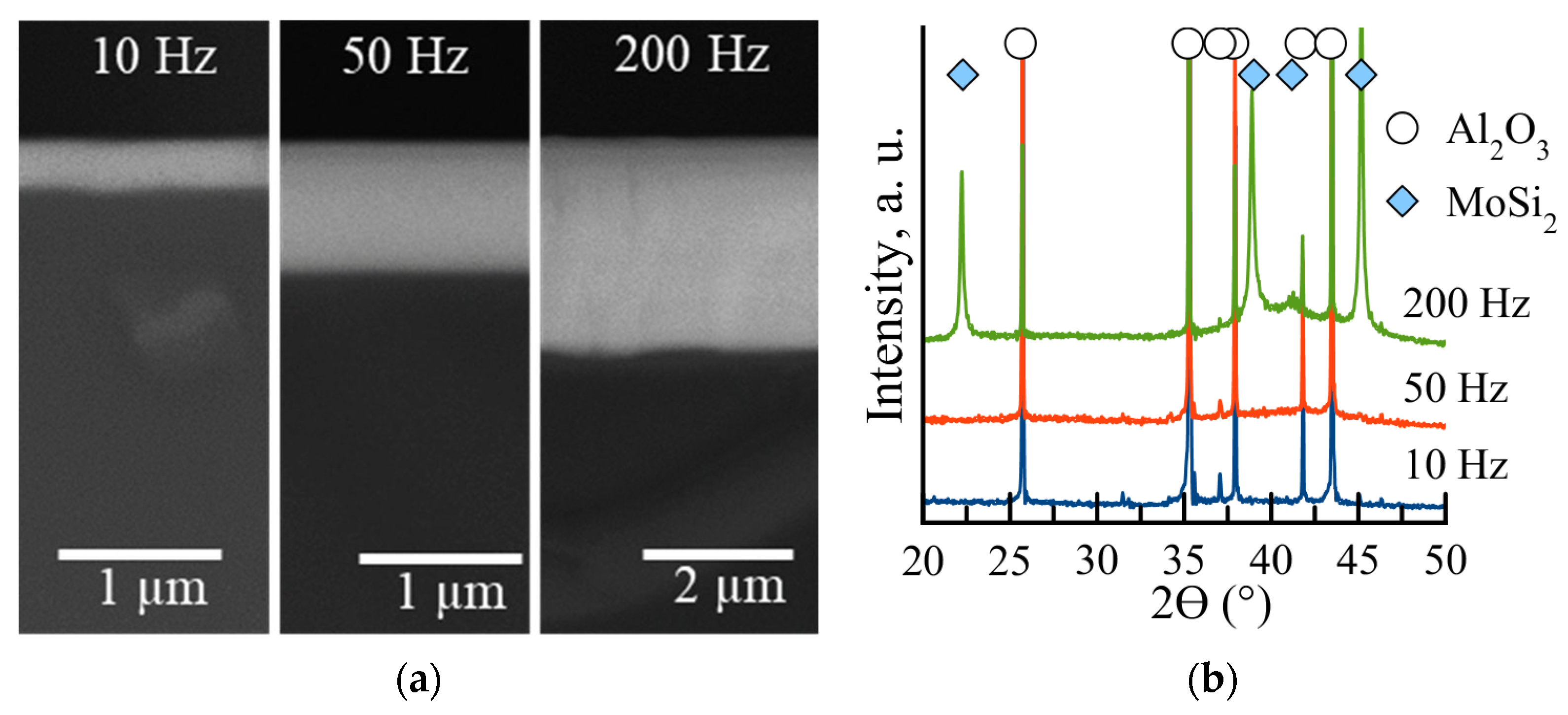
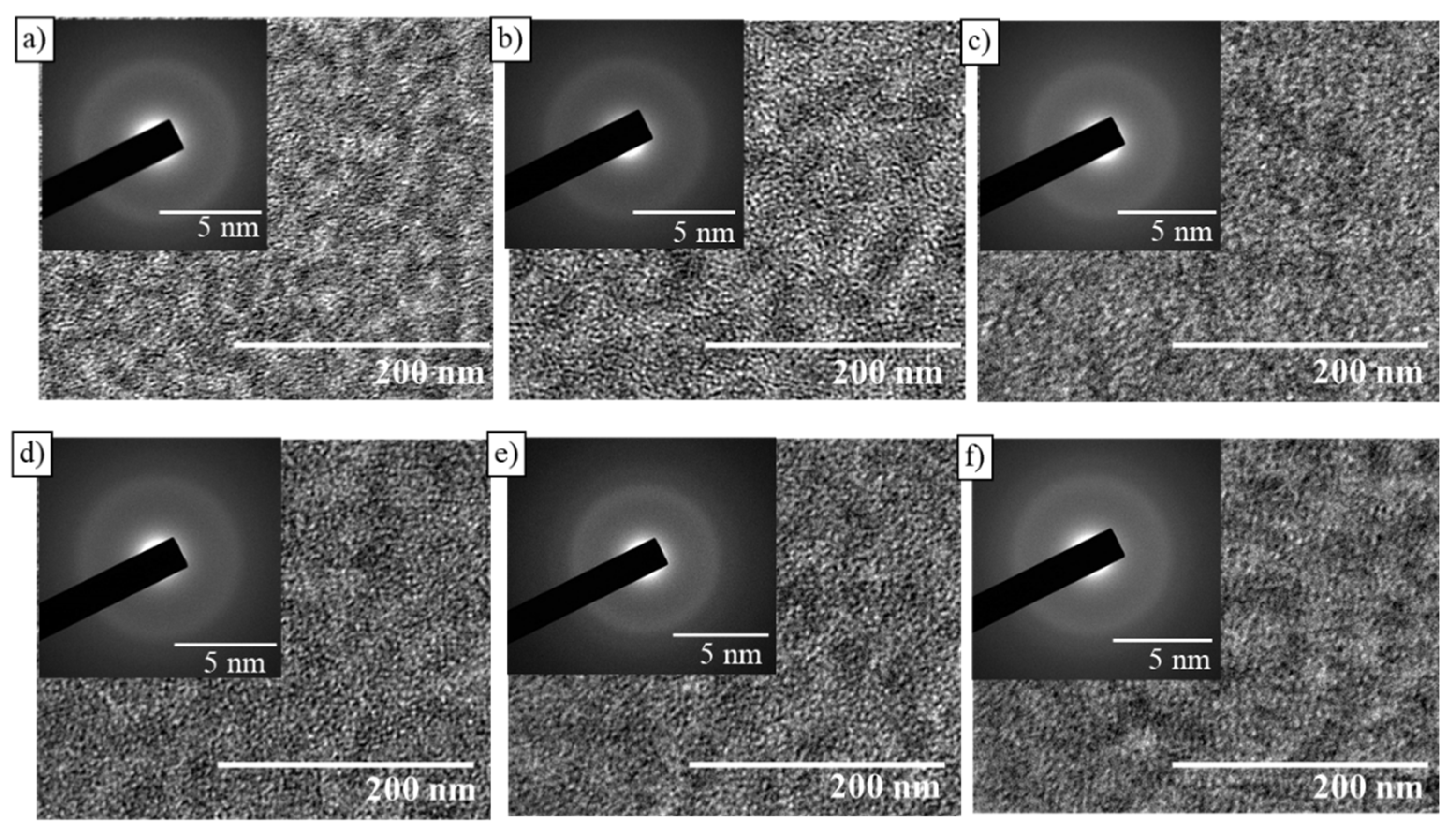
3.2. Composition and Structure

Table 2 summarizes the average thickness concentrations of the main elements of the coatings determined by GDOES.
The sum of the concentrations of carbon and oxygen impurities in the coatings was no higher than 1.1 at.%. Similar concentrations of Mo (25.8–30.1 at.%) and Si (56.8–63.2 at.%) were observed for all the coatings; the Mo/Si ratio was near-stoichiometric. As the pulse frequency increased from 10 to 50 and 200 Hz, the boron concentration rose 1.7–1.8-fold and the zirconium concentration increased 3.2- and 3.8-fold, respectively. This phenomenon can be attributed to the reduction in the peak target current at high-pulse frequencies [21]. A similar change in concentration can take place due to the difference in atom-scattering energy during sputtering [28].
SEM images (Figure 1a) show that the coatings had a dense homogeneous structure, and their thickness increased by 2.3 and 9.0 times as frequency rose from 10 to 50 and 200 Hz, respectively (Table 2).
The minimal thickness (0.3 µm) and growth rate (7.5 nm/min) were observed for the sample deposited at 10 Hz and the maximum peak current (Table 1). It was reported earlier that the high-peak target current increased the ionization rate and plasma density, and the absolute number of ions failing to reach the substrate increased because of the magnetic confinement and return effects [29,30]. As the frequency rose to 50 and 200 Hz, the growth rate increased to 17.5 and 67.5 nm/min, respectively. This may be attributed to the increased sputtering rate of the target and the total flux of sputtered species to the substrate at a high frequency [22]. The low ionization rate at the low-peak current reduced the counter-attraction to the target surface, so a greater number of metal ions and metals were transferred to the substrate, and the deposition rate increased [29]. Furthermore, the reflection or desorption of atoms and ions on the substrate surface decreased because of a weakened ion bombardment at high-pulse frequencies, which also increased the deposition rate [31].
Figure 1b shows the XRD patterns of the coatings. Only peaks belonging to the Al2O3 substrate (ICDD 46-1212) were detected for the samples deposited at pulse frequencies of 10 and 50 Hz because of the low coating thickness < 1 µm. Peaks belonging to h-MoSi2 (ICDD 80-4771) at 2θ = 22.3, 38.9, 41.2, and 45.1° were identified for the sample deposited at 200 Hz. The size of the h-MoSi2 grains determined using the Scherrer formula lay within the range of 40–60 nm. The lattice parameters were a = 0.460 and c = 0.655 nm.

3.3. Mechanical Properties

The nanoindentation tests revealed a linear dependence between the mechanical characteristics and frequency. The coating deposited at 10 Hz was characterized by the minimal hardness H = 8 GPa, Young’s modulus E = 196 GPa, and elastic recovery W = 35% (Table 3).
As the frequency increased, the mechanical properties were improved (H = 23 GPa) for the coating deposited at 200 Hz. The elastic strain to failure H/E and resistance to plastic deformation H3/E2 were also determined using the nanoindentation data, which are important from the perspective of wear resistance and deformation mechanisms [32,33,34]. By analyzing the H/E and H3/E2 ratios, one can assume that the coating deposited at 200 Hz will be characterized by the maximum wear resistance due to the high parameters of H/E = 0.077 and H3/E2 = 0.136 GPa. In this study, the increase in hardness can be attributed to the rising zirconium and boron concentrations in the coatings. The hardness of ZrB2 is known to be higher than that of MoSi2 [35,36]. It can be assumed that the high zirconium and boron contents increase the number of Zr-B bonds and, therefore, increase hardness. Furthermore, the effect of coating thickness on the results of measuring mechanical properties should not be ruled out [37].

3.4. Adhesion Strength

Figure 2 shows the scratch-test parameters as a function of indentation load and the images of scratches recorded using an optical profilometer. An abrupt jump in acoustic emission (AE) at a load of Lc1 = 2 N was observed in the scratch-test curve for the Mo-Zr-Si-B coating deposited on molybdenum at a frequency of 10 Hz, which can be associated with the cracking of the coating. The load Lc3 = 3.2 N can be attributed to the point where the molybdenum substrate started to be deformed by the indenter. In the rest of the region, the AE signal remained constant and was near-zero. No jump was observed in the diagram, showing the dependence between the penetration depth (h) and indentation load; the h value increased linearly from 0 to ~40 µm. For the sample deposited at 50 Hz, the jump in AE associated with cracking was revealed at a load of Lc1 = 2.2 N. The critical load at which the indenter touched the substrate was Lc3 = 4.5 N. The penetration depth increased smoothly from 0 to ~21 µm. For the coating deposited at 200 Hz, the acoustic emission changed jump-wise as the indentation load increased from 1 to 25 N. In this case, Lc1 = 3.1 N. After that, AE declined to zero and remained constant in the region of 25–70 N. The reduction in AE at 25 N was accompanied by a jump in the diagram, showing the dependence between penetration depth and indentation load. This load corresponds to Lc3. By the end of the test, the h value was 34 µm. The difference in penetration depths at the maximum indentation load can be attributed to the different thicknesses and structural features of the coatings.
The minimal penetration depth was observed for the coating deposited at 50 Hz. Radial cracks usually result from the plastic deformation of the substrate and the low strength of the substrate/coating interface [38]. According to the profiles of scratches detected after the scratch tests, in which there was p to a load of 70 N for all the Mo-Zr-Si-B coatings deposited by the HIPIMS method, no delamination was observed, which indicates that these coatings were characterized by high adhesion strength. It should be noted that an adhesion strength of 70 N for Mo-Zr-Si-B HIPIMS coatings is higher than that of the typical coatings obtained on metal substrates by conventional direct current magnetron sputtering [35,36,37,39].

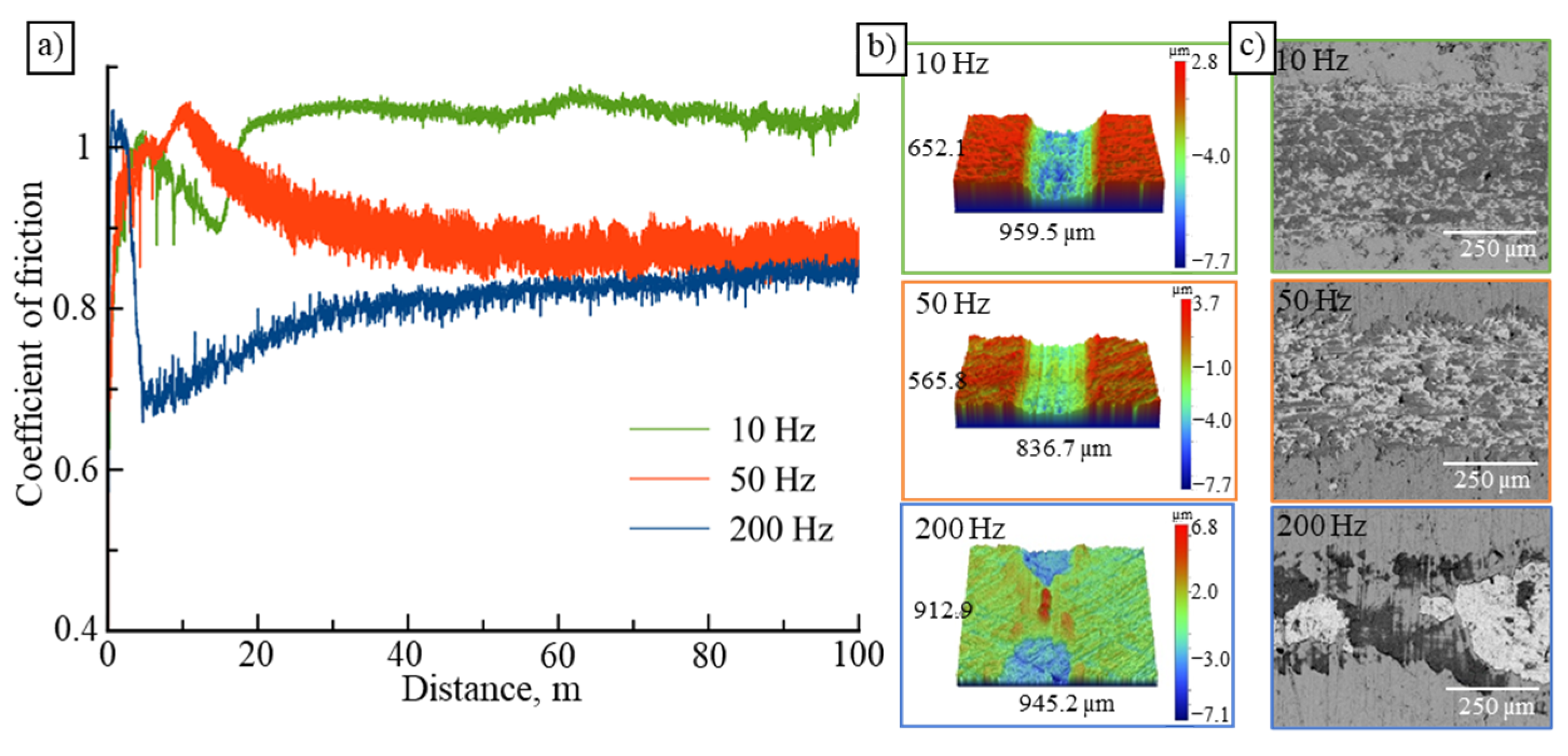
3.5. Tribological Characteristics

The tribology tests revealed that, for all coatings, there was a breaking-in region (at distances up to 15 m), characterized by a high coefficient of friction (f~1.0) (Figure 3). The shortest running-in period was observed for the coating deposited at a frequency of 200 Hz. The coating deposited at 10 Hz was characterized by a high coefficient of friction f~1 (Table 3). As the frequency was increased to 50 Hz, the f value declined to 0.90. The coating deposited at 200 Hz had the minimal f value. The friction coefficients agreed with the previously published data for Mo-Si-B-based coatings [14,40]. The wear rate (Vw) (Table 3) was determined according to the wear track profiles (Figure 3), which was 3.0, 1.9, and 2.3 × 10⁻⁴ mm3·N−1·m−1 for the coatings deposited at 10, 50, and 200 Hz, respectively.
The coatings deposited at 10 and 50 Hz had a similar shape of wear tracks. The coating deposited at 200 Hz was characterized by non-uniform wear. During tribological contact, a counter body was pressed into the ductile molybdenum substrate material until the maximum stress was reached. As a result, different depths were observed along the entire length of the wear track, similarly to the situation reported in [41].

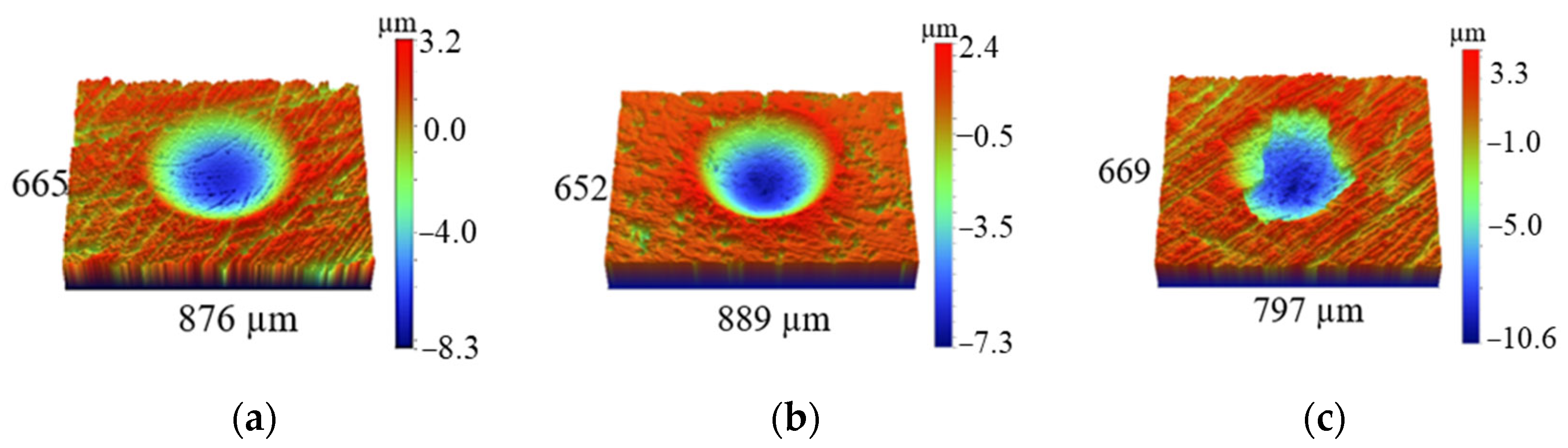
3.6. Resistance to Dynamic Impact Loading

Figure 4 shows the 3D profiles of the craters after the dynamic impact tests of the coatings deposited onto Mo substrates. The crater volumes (V) calculated according to the 2D profiles are summarized in Table 3. The craters of the coatings deposited at frequencies of 10 and 50 Hz had a regular shape, thus indicating that plastic deformation typical of molybdenum prevailed. Signs of brittle failure were observed for the coating deposited at 200 Hz, which is typical of coatings with a high H3/E2 ratio [42]. The crater volumes for the coatings deposited at 10, 50, and 200 Hz were 309, 281, and 561 × 103 µm3, respectively.
The sample deposited at a frequency of 50 Hz exhibited the best wear resistance and resistance to cyclic-dynamic-impact loading, which can be attributed to the low coating thickness, as well as the influence of the substrate. In [42], it is shown that, during impact testing of Zr-Si-B coatings deposited on a molybdenum alloy with H/E = 0.0035, plastic deformation prevailed. At the same time, the substrate was characterized by a smaller crater depth compared to the Zr-Si-B coating, which is associated with the high ductility of Mo-alloys.

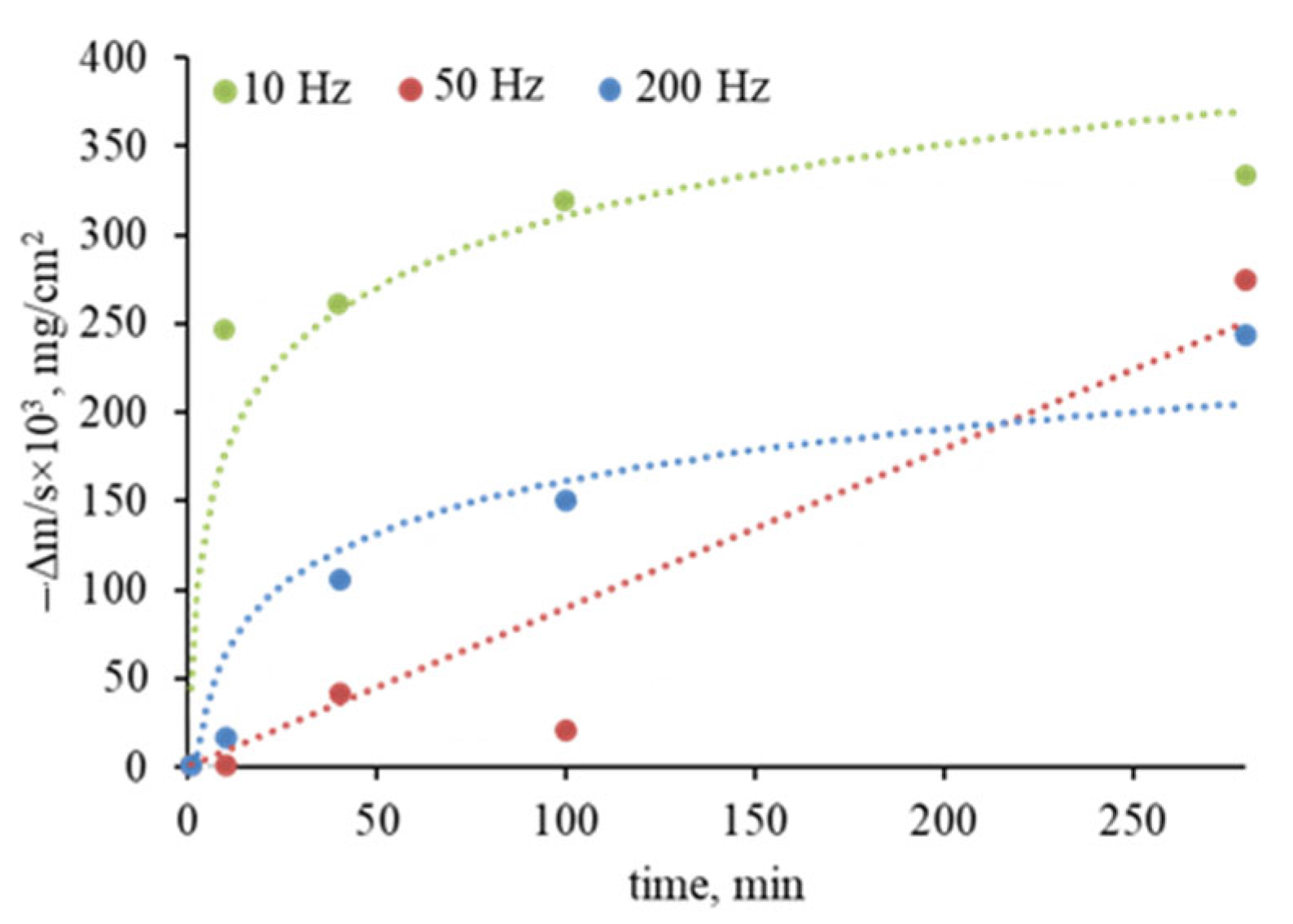
3.7. High-Temperature Oxidation Resistance

Figure 5 shows the results of studies focusing on the oxidation kinetics at 1000 °C.
The mass of the coating deposited at 10 Hz decreased abruptly at an exposure time of 0–60 min due to the rapid oxidation of molybdenum and the evaporation of MoOx [43]. The mass loss (Δm/s) for coating one was the maximum (−0.33 mg/cm2) for an exposure time of 280 min. The mass of the coating deposited at 50 Hz increased (Δm/s = 0.042 mg/cm2) at an exposure time of 0–40 min because of the formation of a SiO2-based oxide layer. The decline in Δm/s to −0.27 mg/cm2 observed in the region of 40–280 min was also caused by the evaporation of molybdenum oxide. Similar results (Δm/s = −0.24 mg/cm2) were obtained for the coating deposited at 200 Hz, in which the evaporation of MoOx was observed at an exposure time of 10–280 min. Note that the coatings obtained at 10 and 200 Hz were oxidized according to parabolic law, which corresponds to the kinetic curves for the bulky samples and Mo-Si-B coatings [44,45]; meanwhile, the coating at an average frequency of 50 Hz oxidized according to linear law. When evaluating the appearance of the annealed samples of the coating deposited at the minimal frequency of 10 Hz, we clearly observed coating degradation resulting from complete oxidation. The oxidation of other samples was accompanied by the formation of a dense protective oxide layer, rather than delamination or critical damage. The best resistance to oxidation at T = 1000 °C, in terms of appearance and kinetic curves, was shown by the coating obtained at 200 Hz.
Annealing at 1300 °C showed that the coating which was deposited at 10 Hz and characterized by minimal thickness was completely oxidized and delaminated. Therefore, SEM studies were performed only for the samples deposited at 50 and 200 Hz (Figure 6). Blistering caused by the evaporation of MoOx was observed on the surface of the coating deposited at 50 Hz. Coating-delamination zones resulted from the collapse of blistered regions. The EDS maps recorded for the cross-section fracture showed that a ~500 nm thick oxide layer was formed on the surface of the coating deposited at 50 Hz (Figure 6). The layer consisted of amorphous silicon oxide with inclusions of ZrO2 crystallites (light-colored regions in the microimages) that preferentially resided in the upper section of the layer (Figure 6). No blistering was observed on the surface of the coating deposited at the maximum frequency (200 Hz), although some local delamination was detected (Figure 6). The structure and thickness of the oxide layer observed at the transverse failure were similar to those of the coating deposited at 50 Hz. Small ZrO2 grains were observed on the surface. It is known that the introduction of zirconium often increases oxidation resistance due to the formation of zirconium oxide particles in a dense oxide layer [46].
Figure 7a shows the XRD data for the coatings annealed at 1300 °C. These findings prove that the coating deposited at the minimal frequency of 10 Hz was completely oxidized: the XRD patterns contained only the peaks corresponding to the Al2O3 substrate and MoOx oxide (ICDD 73-1536). Along with the peaks listed above, lines belonging to the tetragonal t-Mo5Si3 phase (ICDD 34-0371) were identified for the remaining samples. The following phase transformations are known to take place in the Mo-Si-B-based coatings during heating in air: the h-MoSi2 phase is transformed into the t-MoSi2 phase (ICDD 41-0612) at temperatures of ~1000–1200 °C; and the t-Mo5Si3 phase is formed at higher temperatures [13].
Annealing at 1500 °C demonstrated that the coating deposited at a medium-pulse frequency of 50 Hz exhibited good oxidation resistance.
Meanwhile, thermal treatment resulted in the cracking, partial delamination, and oxidation of the coating deposited at 200 Hz. Figure 6 shows the SEM images for the coating deposited at 50 Hz. The agglomeration of irregularly shaped light-colored grains corresponding to zirconium oxide was observed on the coating surface. One can see in the SEM image of the cross-section fracture of the coating that ZrO2 grains are predominantly located in the upper portion of the SiO2-based oxide layer. The thickness of the oxide layer was ~5 µm. The XRD pattern of the coating recorded at temperatures above 1500 °C (Figure 7b) was identical to those observed after annealing at 1300 °C.
Hence, the best high-temperature oxidation resistance was observed for the Mo-Zr-S-B coating deposited by HIPIMS at a medium frequency of 50 Hz, which can be attributed to the relatively small thickness of the coating (~1 µm), which is sufficient to ensure the formation of a protective a-SiO2/nc-ZrO2 film surface during heating, while not causing an accumulation of internal stresses that results in sample degradation during rapid heating or cooling.

3.8. Thermal Stability

An in situ examination of the structural phase transformations occurring in the Mo-Zr-Si-B coating deposited at 50 Hz during stepwise heating in the TEM column was performed. Figure 8 shows the bright-field TEM images of the structure and electron-diffraction patterns of the coating heated within the temperature range of 20–1000 °C.
The as-deposited coating had an amorphous structure, as indicated by the presence of a broad ring in the electron-diffraction pattern. The interplanar distance estimated using the ImageJ software was ~0.270 nm. This value was close to that of the MoSi2 crystalline phase. No noticeable structural phase transformations took place as the temperature was increased to 1000 °C, and the coating remained amorphous.
The next stage of studying the structural phase transformations in Mo-Zr-Si-B coatings involved vacuum annealing at 600, 800, and 1000 °C at an isothermal exposure time of 30 min. No changes in the XRD patterns were observed for the coating deposited at 10 Hz after heating to 1000 °C. For the X-ray amorphous coating deposited at 50 Hz, heating to 600 °C resulted in the emergence of broad peaks at 2Ө = 22.4, 26.3, 35.4, 39.2, 41.6, and 45.5 °, which corresponded to the hexagonal h-MoSi2 phase (Figure 9a).
The intensity of the peaks corresponding to h-MoSi2 increased as the temperature rose to 800 and 1000 °C. The grain size of this phase, which was determined using the Scherrer formula, increased from 7 to 9 and 13 nm as the temperature rose from 600 to 800 and 1000 °C, respectively. The lattice parameters of the hexagonal h-MoSi2 phase remained unchanged as the temperature increased from 600 to 1000 °C and were a = 0.460 and c = 0.655 nm, which corresponded to the tabular data for the h-MoSi2 phase. Heating of the coating deposited at 200 Hz to 600 °C did not cause any qualitative changes in the XRD pattern (Figure 9b). A broad peak (101) at 2θ = 26.1°, corresponding to the hexagonal h-MoSi2 phase, emerged at 800 °C, in addition to the peaks detected earlier. These changes may be associated with the onset of recrystallization. As the temperature rose to 800 °C, the lattice parameters a and c declined to 0.459 and 0.652 nm, respectively. Peaks at 2θ = 22.7, 30.3, 39.9, 44.8, and 46.3°, corresponding to the t-MoSi2 phase, were detected at T = 1000 °C. The grain size of the tetragonal t-MoSi2 phase was ~70 nm. The low-intensity peaks belonging to the hexagonal h-MoSi2 phase were observed at 2θ = 26.1 and 41.2°.
The differences in the TEM and XRD data for the coating deposited at 50 Hz can be explained by the different exposure times and cooling rates during thermal treatment in the TEM column and in the vacuum furnace. In the case of stepwise heating in the TEM column to temperatures up to 1000 °C, the exposure time was 30–40 min, while it was 10 min for the temperature of 1000 °C; the cooling rate of the sample was ~100 °C/min. In these temperature modes, the coating had an amorphous structure in the entire temperature range of 20–1000 °C. Vacuum annealing was carried out for 30 min for all the temperatures. The cooling rate was ~10 °C/min, i.e., the sample was exposed to higher temperatures for a longer time. This is a plausible reason for the recrystallization detected in the annealed coatings. A similar effect of the cooling rate on the structure of Zn-Mg-Al coatings was reported in [47]. Additionally, the reason for the difference between the TEM and XRD data could be related to the local recrystallization of the coating as a result of vacuum annealing, which is not easy to observe in TEM.
The mechanical characteristics of the coatings subjected to vacuum annealing at 1000 °C were studied (Figure 10).
The hardness and elastic recovery of the coating deposited at 10 Hz were H = 10 GPa and W = 46%, being higher than those of the initial coating by 25% and 30%, respectively. Young’s modulus decreased by 15% as the temperature was increased from 20 to 1000 °C. For the coating deposited at 50 Hz, vacuum annealing at 1000 °C made H and E increase to 37 GPa and 380 GPa, respectively. The self-hardening effect observed for the Mo-Zr-Si-B coating deposited at 50 Hz could be related to the partial recrystallization of the amorphous coating and the formation of a nanocomposite structure at 1000 °C [30]. For the coating deposited at 200 Hz and characterized by the maximum mechanical characteristics in its initial state, the H and E parameters decreased by 56 and 25%, respectively, as the temperature was increased to 1000 °C, while W increased by 35%. This effect was related to phase transformations and the fact that the predominating phase in the structure after annealing was the tetragonal t-MoSi2 phase, which was characterized by a lower hardness compared to that of the hexagonal h-MoSi2 phase [48]. The samples before and after annealing were studied using a profilometer to determine the radius of the curvature of the coated lamellae and to subsequently calculate the internal stresses using the Stoney formula. The levels of internal stresses affecting the mechanical properties of the coatings were similar at all the frequencies used in the temperature range of 20–1000 °C.

4. Conclusions

  • The Mo-Zr-Si-B coatings deposited by HIPIMS at frequencies of 10, 50, and 200 Hz had a dense and homogeneous structure. The minimal growth rate (7.5 nm/min) was observed at 10 Hz for the highest maximum peak current. As frequency was increased to 50 and 200 Hz, the growth rate rose to 17.5 and 67.5 nm/min, respectively.
  • The hardness of the Mo-Zr-Si-B coatings deposited at 10, 50, and 200 Hz was 8, 15, and 23 GPa, respectively. The coating deposited at 50 Hz was characterized by a higher resistance to wear and cyclic-dynamic-impact loading, as well as high-temperature oxidation resistance at 1300 and 1500 °C.
  • Heating in the transmission electron microscope column at temperatures of 20–1000 °C did not result in structural changes, and the coating deposited at 50 Hz remained amorphous. The segregation and growth of MoSi2 phase grains were observed in the temperature range of 600–1000 °C during vacuum annealing because of the longer exposure time and low heating/cooling rates. The hardness and Young’s modulus of the coatings deposited at frequencies of 10 and 200 Hz decreased after vacuum annealing. The self-hardening effect was detected for the coating deposited at 50 Hz. As the temperature rose from 20 to 1000 °C, the hardness and Young’s modulus increased from 15 and 250 GPa to 37 and 380 GPa, respectively, due to the crystallization process and the transformation of the amorphous structure into a nanocomposite one.

Author Contributions

Conceptualization, P.V.K.-K.; Formal analysis, A.D.S.; Investigation, P.V.K.-K., A.D.S., P.A.L. and A.S.O.; Project administration, E.A.L.; Resources, E.A.L.; Writing—review & editing, P.V.K.-K. and A.S.O. All authors have read and agreed to the published version of the manuscript.

Funding

This work was performed with financial support from the Russian Science Foundation (project No. 19-19-00117-П).

Institutional Review Board Statement

Not applicable.

Informed Consent Statement

Not applicable.

Data Availability Statement

Not applicable.

Acknowledgments

The authors are grateful to M.I. Petrzhik for the nanoindentation tests and N.V. Shvyndina for the SEM-EDS study.

Conflicts of Interest

The authors declare no conflict of interest.

References

  1. Li, H.; Yao, D.; Fu, Q.; Liu, L.; Zhang, Y.; Yao, X.; Wang, Y.; Li, H. Anti-Oxidation and Ablation Properties of Carbon/Carbon Composites Infiltrated by Hafnium Boride. Carbon 2013, 52, 418–426. [Google Scholar] [CrossRef]
  2. Grigoriev, S.N.; Vereschaka, A.A.; Volosova, M.A.; Sitnikov, N.N.; Sotova, E.S.; Seleznev, A.E.; Bublikov, J.I.; Batako, A.D. Improved Efficiency of Ceramic Cutting Tools in Machining Hardened Steel—An Application with Nanostructured Multilayered Coatings. Handb. Mod. Coat. Technol. 2021, 381–433. [Google Scholar] [CrossRef]
  3. Kim, Y.H.; Shin, T.H.; Myung, J. ha MoSi2-Based Cylindrical Susceptor for Rapid High-Temperature Induction Heating in Air. Ceram. Int. 2020, 46, 23636–23642. [Google Scholar] [CrossRef]
  4. Feng, P.; Wu, J.; Islam, S.H.; Liu, W.; Niu, J.; Wang, X.; Qiang, Y. Effects of Boron Addition on the Formation of MoSi2 by Combustion Synthesis Mode. J. Alloys Compd. 2010, 494, 161–165. [Google Scholar] [CrossRef]
  5. Zhang, L.; Tong, Z.; He, R.; Xie, C.; Bai, X.; Yang, Y.; Fang, D. Key Issues of MoSi2-UHTC Ceramics for Ultra High Temperature Heating Element Applications: Mechanical, Electrical, Oxidation and Thermal Shock Behaviors. J. Alloys Compd. 2019, 780, 156–163. [Google Scholar] [CrossRef]
  6. Xin, L.; Chen, Q.; Teng, Y.; Wang, W.; Sun, A.; Zhu, S.; Wang, F. Effects of Silicon and Multilayer Structure of TiAl(Si)N Coatings on the Oxidation Resistance of Ti6Al4V. Surf. Coat. Technol. 2013, 228, 48–58. [Google Scholar] [CrossRef]
  7. Bae, K.E.; Chae, K.W.; Park, J.K.; Lee, W.S.; Baik, Y.J. Oxidation Behavior of Amorphous Boron Carbide–Silicon Carbide Nano-Multilayer Thin Films. Surf. Coat. Technol. 2015, 276, 55–58. [Google Scholar] [CrossRef]
  8. Niu, Y.; Wang, H.; Li, H.; Zheng, X.; Ding, C. Dense ZrB2-MoSi2 Composite Coating Fabricated by Low Pressure Plasma Spray (LPPS). Ceram. Int. 2013, 39, 9773–9777. [Google Scholar] [CrossRef]
  9. Ren, X.; Li, H.; Chu, Y.; Li, K.; Fu, Q. ZrB2–SiC Gradient Oxidation Protective Coating for Carbon/Carbon Composites. Ceram. Int. 2014, 40, 7171–7176. [Google Scholar] [CrossRef]
  10. Zhestkov, B.E.; Terent’eva, V.S. Multifunctional Coating MAI D5 Intended for the Protection of Refractory Materials. Russ. Metall. 2010, 2010, 33–40. [Google Scholar] [CrossRef]
  11. Yang, J.; Liu, H.; Gao, W.; Su, L.; Jiang, K. Effect of Different Fillers on the Microstructural Evolution and High Temperature Oxidation Resistance of Mo-Si-B Coatings Prepared by Pack Cementation. Int. J. Refract. Met. Hard Mater. 2021, 100, 105625. [Google Scholar] [CrossRef]
  12. Shrestha, S.; Hodgkiess, T.; Neville, A. Erosion–Corrosion Behaviour of High-Velocity Oxy-Fuel Ni–Cr–Mo–Si–B Coatings under High-Velocity Seawater Jet Impingement. Wear 2005, 259, 208–218. [Google Scholar] [CrossRef]
  13. Kiryukhantsev-Korneev, P.V.; Iatsyuk, I.V.; Shvindina, N.V.; Levashov, E.A.; Shtansky, D.V. Comparative Investigation of Structure, Mechanical Properties, and Oxidation Resistance of Mo-Si-B and Mo-Al-Si-B Coatings. Corros. Sci. 2017, 123, 319–327. [Google Scholar] [CrossRef]
  14. Kiryukhantsev-Korneev, P.V.; Sytchenko, A.D.; Sviridova, T.A.; Sidorenko, D.A.; Andreev, N.V.; Klechkovskaya, V.V.; Polčak, J.; Levashov, E.A. Effects of Doping with Zr and Hf on the Structure and Properties of Mo-Si-B Coatings Obtained by Magnetron Sputtering of Composite Targets. Surf. Coat. Technol. 2022, 442, 128141. [Google Scholar] [CrossRef]
  15. Veprek, S.; Jilek, M. Super- and Ultrahard Nanacomposite Coatings: Generic Concept for Their Preparation, Properties and Industrial Applications. Vacuum 2002, 67, 443–449. [Google Scholar] [CrossRef]
  16. Kelly, P.J.; Beevers, C.F.; Henderson, P.S.; Arnell, R.D.; Bradley, J.W.; Bäcker, H. A Comparison of the Properties of Titanium-Based Films Produced by Pulsed and Continuous DC Magnetron Sputtering. Surf. Coat. Technol. 2003, 174–175, 795–800. [Google Scholar] [CrossRef]
  17. Elmkhah, H.; Attarzadeh, F.; Fattah-alhosseini, A.; Kim, K.H. Microstructural and Electrochemical Comparison between TiN Coatings Deposited through HIPIMS and DCMS Techniques. J. Alloys Compd. 2018, 735, 422–429. [Google Scholar] [CrossRef]
  18. Helmersson, U.; Lattemann, M.; Bohlmark, J.; Ehiasarian, A.P.; Gudmundsson, J.T. Ionized Physical Vapor Deposition (IPVD): A Review of Technology and Applications. Thin Solid Films 2006, 513, 1–24. [Google Scholar] [CrossRef] [Green Version]
  19. Lattemann, M.; Ehiasarian, A.P.; Bohlmark, J.; Persson, P.Å.O.; Helmersson, U. Investigation of High Power Impulse Magnetron Sputtering Pretreated Interfaces for Adhesion Enhancement of Hard Coatings on Steel. Surf. Coat. Technol. 2006, 200, 6495–6499. [Google Scholar] [CrossRef] [Green Version]
  20. Lu, C.Y.; Diyatmika, W.; Lou, B.S.; Lu, Y.C.; Duh, J.G.; Lee, J.W. Influences of Target Poisoning on the Mechanical Properties of TiCrBN Thin Films Grown by a Superimposed High Power Impulse and Medium-Frequency Magnetron Sputtering. Surf. Coat. Technol. 2017, 332, 86–95. [Google Scholar] [CrossRef]
  21. Mei, H.; Ding, J.C.; Xiao, X.; Luo, Q.; Wang, R.; Zhang, Q.; Gong, W.; Wang, Q. Influence of Pulse Frequency on Microstructure and Mechanical Properties of Al-Ti-V-Cu-N Coatings Deposited by HIPIMS. Surf. Coat. Technol. 2021, 405, 126514. [Google Scholar] [CrossRef]
  22. Nedfors, N.; Mockute, A.; Palisaitis, J.; Persson, P.O.Å.; Näslund, L.Å.; Rosen, J. Influence of Pulse Frequency and Bias on Microstructure and Mechanical Properties of TiB2 Coatings Deposited by High Power Impulse Magnetron Sputtering. Surf. Coat. Technol. 2016, 304, 203–210. [Google Scholar] [CrossRef] [Green Version]
  23. Dai, W.; Kwon, S.H.; Wang, Q.; Liu, J. Influence of Frequency and C2H2 Flow on Growth Properties of Diamond-like Carbon Coatings with AlCrSi Co-Doping Deposited Using a Reactive High Power Impulse Magnetron Sputtering. Thin Solid Films 2018, 647, 26–32. [Google Scholar] [CrossRef]
  24. Samuelsson, M.; Sarakinos, K.; Högberg, H.; Lewin, E.; Jansson, U.; Wälivaara, B.; Ljungcrantz, H.; Helmersson, U. Growth of Ti-C Nanocomposite Films by Reactive High Power Impulse Magnetron Sputtering under Industrial Conditions. Surf. Coat. Technol. 2012, 206, 2396–2402. [Google Scholar] [CrossRef] [Green Version]
  25. Polaček, M.; Souček, P.; Alishahi, M.; Koutná, N.; Klein, P.; Zábranský, L.; Czigány, Z.; Balázsi, K.; Vašina, P. Synthesis and Characterization of Ta–B–C Coatings Prepared by DCMS and HiPIMS Co-Sputtering. Vacuum 2022, 199, 110937. [Google Scholar] [CrossRef]
  26. Kiryukhantsev-Korneev, F.V. Possibilities of Glow Discharge Optical Emission Spectroscopy in the Investigation of Coatings. Russ. J. Non-Ferrous Met. 2014, 55, 494–504. [Google Scholar] [CrossRef]
  27. Daghbouj, N.; Sen, H.S.; Čížek, J.; Lorinčík, J.; Karlík, M.; Callisti, M.; Čech, J.; Havránek, V.; Li, B.; Krsjak, V.; et al. Characterizing Heavy Ions-Irradiated Zr/Nb: Structure and Mechanical Properties. Mater. Des. 2022, 219, 110732. [Google Scholar] [CrossRef]
  28. Shimizu, T.; Teranishi, Y.; Morikawa, K.; Komiya, H.; Watanabe, T.; Nagasaka, H.; Yang, M. Impact of Pulse Duration in High Power Impulse Magnetron Sputtering on the Low-Temperature Growth of Wurtzite Phase (Ti,Al)N Films with High Hardness. Thin Solid Films 2015, 581, 39–47. [Google Scholar] [CrossRef]
  29. Papa, F.; Gerdes, H.; Bandorf, R.; Ehiasarian, A.P.; Kolev, I.; Braeuer, G.; Tietema, R.; Krug, T. Deposition Rate Characteristics for Steady State High Power Impulse Magnetron Sputtering (HIPIMS) Discharges Generated with a Modulated Pulsed Power (MPP) Generator. Thin Solid Films 2011, 520, 1559–1563. [Google Scholar] [CrossRef]
  30. Sarakinos, K.; Alami, J.; Konstantinidis, S. High Power Pulsed Magnetron Sputtering: A Review on Scientific and Engineering State of the Art. Surf. Coat. Technol. 2010, 204, 1661–1684. [Google Scholar] [CrossRef]
  31. Bobzin, K.; Brögelmann, T.; Brugnara, R.H. Aluminum-Rich HPPMS (Cr1−xAlx)N Coatings Deposited with Different Target Compositions and at Various Pulse Lengths. Vacuum 2015, 122, 201–207. [Google Scholar] [CrossRef]
  32. Musil, J.; Novák, P.; Čerstvý, R.; Soukup, Z. Tribological and Mechanical Properties of Nanocrystalline-TiC/a-C Nanocomposite Thin Films. J. Vac. Sci. Technol. Vacuum Surfaces Film. 2010, 28, 244. [Google Scholar] [CrossRef]
  33. Leyland, A.; Matthews, A. Optimization of Nanostructured Tribological Coatings. In Nanostructured Coatings. Nanostructure Science and Technology; Cavaleiro, A., de Hosson, J.T.M., Eds.; Springer: New York, NY, USA, 2006; pp. 511–538. [Google Scholar]
  34. Ge, F.F.; Sen, H.S.; Daghbouj, N.; Callisti, M.; Feng, Y.J.; Li, B.S.; Zhu, P.; Li, P.; Meng, F.P.; Polcar, T.; et al. Toughening Mechanisms in V-Si-N Coatings. Mater. Des. 2021, 209, 109961. [Google Scholar] [CrossRef]
  35. Berg, G.; Friedrich, C.; Broszeit, E.; Berger, C. Data Collection of Properties of Hard Material. Handb. Ceram. Hard Mater. 2008, 965–995. [Google Scholar] [CrossRef]
  36. Gutman, M.B. Materials for Electrothermal Plants: Handbook; Energoatomizdat: Moscow, Russia, 1987. (in Russian) [Google Scholar]
  37. Veprek, S.; Mukherjee, S.; Karvankova, P.; Männling, H.D.; He, J.L.; Moto, K.; Prochazka, J.; Argon, A.S. Hertzian Analysis of the Self-Consistency and Reliability of the Indentation Hardness Measurements on Superhard Nanocomposite Coatings. Thin Solid Films 2003, 436, 220–231. [Google Scholar] [CrossRef]
  38. Rezakhanlou, R.; von Stebut, J. Paper VII (Iii) Damage Mechanisms of Hard Coatings on Hard Substrates: A Critical Analysis of Failure in Scratch and Wear Testing. Tribol. Ser. 1990, 17, 183–192. [Google Scholar] [CrossRef]
  39. Kiryukhantsev-Korneev, P.V.; Sheveyko, A.N.; Vorotilo, S.A.; Levashov, E.A. Wear-Resistant Ti–Al–Ni–C–N Coatings Produced by Magnetron Sputtering of SHS-Targets in the DC and HIPIMS Modes. Ceram. Int. 2020, 46, 1775–1783. [Google Scholar] [CrossRef]
  40. Kudryashov, A.E.; Lebedev, D.N.; Potanin, A.Y.; Levashov, E.A. Structure and Properties of Coatings Produced by Pulsed Electrospark Deposition on Nickel Alloy Using Mo-Si-B Electrodes. Surf. Coat. Technol. 2018, 335, 104–117. [Google Scholar] [CrossRef]
  41. Xi, H.H.; He, P.F.; Wang, H.D.; Liu, M.; Chen, S.Y.; Xing, Z.G.; Ma, G.Z.; Lv, Z.L. Microstructure and Mechanical Properties of Mo Coating Deposited by Supersonic Plasma Spraying. Int. J. Refract. Met. Hard Mater. 2020, 86, 105095. [Google Scholar] [CrossRef]
  42. Kiryukhantsev-Korneev, P.V.; Sytchenko, A.D. Influence of Physical and Mechanical Properties of the Substrate on the Behavior of Zr–Si–B Coatings under Sliding Friction and Cyclic Impact-Dynamic Loading. Prot. Met. Phys. Chem. Surfaces 2020, 56, 981–989. [Google Scholar] [CrossRef]
  43. Perepezko, J.H. High Temperature Environmental Resistant Mo-Si-B Based Coatings. Int. J. Refract. Met. Hard Mater. 2018, 71, 246–254. [Google Scholar] [CrossRef]
  44. Deng, X.; Zhang, G.; Wang, T.; Ren, S.; Shi, Y.; Bai, Z.; Cao, Q. Microstructure and Oxidation Resistance of a Multiphase Mo-Si-B Ceramic Coating on Mo Substrates Deposited by a Plasma Transferred Arc Process. Ceram. Int. 2019, 45, 415–423. [Google Scholar] [CrossRef]
  45. Wang, F.; Shan, A.; Dong, X.; Wu, J. Oxidation Behavior of Mo–12.5Si–25B Alloy at High Temperature. J. Alloys Compd. 2008, 459, 362–368. [Google Scholar] [CrossRef]
  46. Yang, Y.; Bei, H.; Chen, S.; George, E.P.; Tiley, J.; Chang, Y.A. Effects of Ti, Zr, and Hf on the Phase Stability of Mo_ss + Mo3Si + Mo5SiB2 Alloys at 1600 °C. Acta Mater. 2010, 58, 541–548. [Google Scholar] [CrossRef]
  47. Ha, Y.; Kim, T.C.; Baeg, J.H.; Kim, J.S.; Shon, M.; Cho, Y.R. Effect of Cooling Rate on Surface Properties of ZnMgAl Coating and Adhesion to Epoxy Adhesive. Int. J. Adhes. Adhes. 2022, 117, 103182. [Google Scholar] [CrossRef]
  48. Guo, Z.; Zhang, L.; Qiao, Y.; Gao, Q.; Xiao, Z. A New C11b-Type High Entropy Refractory Metal Silicide to Improve MoSi2 Mechanical Properties More Easily. Scr. Mater. 2022, 218, 114798. [Google Scholar] [CrossRef]
Figure 1. Cross-section SEM images of coatings (a) and the respective XRD patterns (b).
Coatings 12 01570 g001
Figure 2. Scratch-test parameters as a function of indenter load and the scratch profiles after testing of Mo-Zr-Si-B coatings deposited by HIPIMS at frequencies of 10 (a), 50 (b), and 200 Hz (c).
Coatings 12 01570 g002
Figure 3. The coefficient of friction (a) as a function of distance, the 3D profiles (b) and SEM images of tribocontact zone (c) of the Mo-Zr-Si-B coatings deposited at 10, 50, and 200 Hz.
Coatings 12 01570 g003
Figure 4. The 3D profiles of craters after dynamic impact tests of the Mo-Zr-Si-B samples deposited by HIPIMS at frequencies of 10 (a), 50 (b), and 200 Hz (c).
Coatings 12 01570 g004
Figure 5. Changes in specific weight of the Mo-Zr-Si-B coatings deposited by HIPIMS onto an Al2O3 substrate at frequencies of 10, 50, and 200 Hz as a function of time of annealing at 1000 °C.
Coatings 12 01570 g005
Figure 6. SEM images of the surface (a,c,e) and cross-section fracture (b,d,f) of the coatings deposited at frequencies of 50 (a,b,e,f) and 200 Hz (c,d) after annealing in air at 1300 and 1500 °C.
Coatings 12 01570 g006
Figure 7. X-ray diffraction patterns of the Mo-Zr-Si-B coatings annealed in air at 1300 °C (a) and the coating deposited at 50 Hz and annealed at 1500 °C (b).
Coatings 12 01570 g007
Figure 8. TEM images and electron-diffraction patterns of the Mo-Zr-Si-B coating deposited by HIPIMS (50 Hz) at temperatures 20 (a), 200 (b), 400 (c), 600 (d), 800 (e) and 1000 °C (f).
Coatings 12 01570 g008
Figure 9. X-ray diffraction patterns of the Mo-Zr-Si-B coatings deposited by HIPIMS at 50 (a) and 200 Hz (b), in the as-deposited state and after vacuum annealing at T = 600, 800, and 1000 °C.
Coatings 12 01570 g009
Figure 10. Hardness (a), Young’s modulus (b), and elastic recovery (c) of Mo-Zr-Si-B coatings in the as-deposited state and after vacuum annealing at 1000 °C.
Coatings 12 01570 g010
Table 1. Coating deposition parameters.
Deposition ParametersCoating 1Coating 2Coating 3
Frequency, Hz1050200
Pulse duration, µs200200200
Pulse voltage, V940950963
Pulse current, A422227
Average power, kW0.10.21
Maximum peak power, kW353030
Maximum peak current, A3325–3030
Table 2. The composition (according to the GDOES data), thickness, and growth rate of coatings.
Frequency, HzElemental Composition, at.%Thickness, µmGrowth Rate, nm/min
MoSiBZrC + O
1030.1 ± 1.363.2 ± 1.25.3 ± 0.21.2 ± 0.10.2 ± 0.10.37.5
5025.8 ± 1.360.2 ± 1.49.1 ± 0.43.8 ± 0.21.1 ± 0.40.717.5
20028.0 ± 2.056.8 ± 1.59.6 ± 0.44.5 ± 0.41.1 ± 0.42.767.5
Table 3. Mechanical and tribological properties of the coatings.
Frequency,
Hz
H, GPaE, GPaW, %H/EH3/E2, GPafVw, ×10−4 mm3·N−1·m−1V, ×103 µm3
108 ± 1196 ± 2935 ± 40.0410.0131.013.0309
5015 ± 3251 ± 3044 ± 60.0600.0540.901.9281
20023 ± 3299 ± 1865 ± 40.0770.1360.812.3561
H—hardness; E—Young’s modulus; W—elastic recovery; H/E—elastic strain to failure; H3/E2—resistance to plastic deformation; f—coefficient of friction; Vw—wear rate; V—crater volume.
Publisher’s Note: MDPI stays neutral with regard to jurisdictional claims in published maps and institutional affiliations.

