Article

The Effect of Argon as Atomization Gas on the Microstructure, Machine Hammer Peening Post-Treatment, and Corrosion Behavior of Twin Wire Arc Sprayed (TWAS) ZnAl4 Coatings

1
Institute of Materials Engineering, TU Dortmund University, Leonhard-Euler-Str. 2, 44227 Dortmund, Germany
2
Institute of Machining Technology, TU Dortmund University, Baroper Str. 303, 44227 Dortmund, Germany
3
Institute of Materials Test Engineering, TU Dortmund University, Baroper Str. 303, 44227 Dortmund, Germany
*
Author to whom correspondence should be addressed.
Wolfgang Tillmann is chair of Materials Engineering; Frank Walther is chair of Materials Test Engineering.
Coatings 2022, 12(1), 32; https://doi.org/10.3390/coatings12010032
Submission received: 27 November 2021 / Revised: 21 December 2021 / Accepted: 23 December 2021 / Published: 27 December 2021

Abstract

:
In the twin wire arc spraying (TWAS) process, it is common to use compressed air as atomizing gas. Nitrogen or argon also are used to reduce oxidation and improve coating performance. The heat required to melt the feedstock material depends on the electrical conductivity of the wires used and the ionization energy of both the feedstock material and atomization gas. In the case of ZnAl4, no phase changes were recorded in the obtained coatings by using either compressed air or argon as atomization gas. This fact has led to the assumption that the melting behavior of ZnAl4 with its low melting and evaporating temperature is different from materials with a higher melting point, such as Fe and Ni, which also explains the unexpected compressive residual stresses in the as-sprayed conditions. The heavier atomization gas, argon, led to slightly higher compressive stresses and oxide content. Compressed air as atomization gas led to lower porosity, decreased surface roughness, and better corrosion resistance. In the case of argon, Al precipitated in the form of small particles. The post-treatment machine hammer peening (MHP) has induced horizontal cracks in compressed air sprayed coatings. These cracks were mainly initiated in the oxidized Al phase.

1. Introduction

In the twin wire arc spraying (TWAS) process, the spray particles are atomized off the molten part of the intersecting wires by a steady and continuous fast-moving atomization gas stream [1,2,3,4,5]. The arc ignition in the TWAS process determines the primary stage of the particle initiation, where the arc melts the feedstock material, and the atomization gas detaches droplets, in subsequent process stages known as spray particles, out of the molten parts of the feedstock [1,3]. The formation of these droplets depends directly on the wires used, the adjusted arc energy, type and pressure of the atomization gas, and the nozzle configuration. In the TWAS process, the spray plume consists of the atomized particles in a molten state and the atomization “carrier” gas at room temperature. This constellation controls the heat input into the substrate material. Compared to the other thermal spraying techniques, the TWAS process reveals the lowest thermal effect, even though the spray particles are atomized in a fully molten state [1,3,6]. However, the atomization gas’s ionization energy, density, and velocity directly control the spray particle size, temperature, and velocity. High atomization gas velocity with low turbulence led to smaller and faster spray particles, which, in turn, produced coating with low porosity and oxide content, as well as increased adhesion [5,7,8].
In particular, the oxidation of the spray particles is a crucial issue in the obtained quality of TWAS sprayed coatings. Some researchers have claimed that the increase in oxide content led to higher coating hardness and improved the coatings’ wear resistance and friction behavior [8,9]. Bolot et al. [4] have an opposite opinion and considered the higher oxide content inconvenient for wear and corrosion applications. They argued that the higher oxide content led to the reduction in coating adhesion and cohesion. Both properties are essential for wear and corrosion applications. Zeng et al. [10], in agreement with Bolot [4], concluded that the creation of local electrochemical cells by the oxide formation in the obtained coatings is the reason for decreased corrosion resistance. However, a significant number of researchers have considered the higher oxidation to be generally detrimental to coating properties [4,6,10,11]. In the particular case of corrosion protection, a lower oxide content and porosity level are essential requirements for the coatings to be applied [1,4,10,12].
The atomization gas type in the TWAS process directly affects the induced heat in the ignited arc and the oxidation of the molten feedstock material [5,12,13,14,15,16,17]. Using either Nitrogen or argon led to coatings with lower porosity and oxide content [5,12,14]. Therefore, it is an indication that in the TWAS process, the oxidation occurs predominantly during the primary and subsequent atomization phase of the spraying particles and to a limited extent during impact and splat formation. Regarding Newbery et al. in [12] and Planche et al. in [13], particle oxidation occurs during the in-flight phase and directly after the impact with the prepared substrate surface. Sacriste et al. [15] found that most oxidation in the TWAS process occurred only during the in-flight phase of the spraying particles and explained that with the decrease in the oxide content at a higher particle velocity.
Using Nitrogen as an atomization gas led to better carbon retention and, therefore, allowed an increase in hardness for a given oxide content [16]. Watanabe et al. [5] found that using Nitrogen as atomization gas stabilizes the arc even at lower currents because of the reduced oxidation and turbulence at the electrode tips. Using heavy gases, such as argon, increased the gas pressure around the arc zone and improved electrode atomization [15]. Tillmann et al. [14] found that the higher ionization energy of argon does not allow for low setting values of voltage and current in the TWAS process. The high power required by arc ignition led to the surmise that the induced heat was higher in the case of argon compared to compressed air [14].
The phenomena described above will have a higher effect on low melting materials, such as in the case of ZnAl4, which is widely used for corrosion protection. The impact includes the melting and atomization behavior of ZnAl4 wires, shape, and content of the spray plume, deposition behavior, and coating build-up. The low melting point of ZnAl4 of 382 °C allows for a narrow range of parameter settings and, thus, limits the coating improvement by only adjusting the proper spray parameter. Furthermore, the high inherent arc temperature of about (4000 to 6000 K) [1,3] may lead to an evaporation of the constituent parts of ZnAl4. Therefore, it may directly or indirectly affect the oxide content and distribution, phase changes, and coating porosity. In addition, the very fast droplet solidification at cooling rates of about 106–107 Ks−1 was found to be the reason for the formation of the amorphous phases [18] and the initiation of higher tensile residual stresses in the TWAS sprayed coatings [19,20,21]. Therefore, it is common that TWAS sprayed coatings require a post-treatment to achieve the required coating microstructure.
In general, improving the performance of TWAS sprayed coatings requires a deliberate change of their microstructure, hardness, and residual stress conditions. Shot peening (SP), machine hammer peening (MHP), and deep rolling (DR) are examples of the applied mechanical post-treatment processes on thermal sprayed coatings to improve their fatigue, corrosion, and wear behavior directly [22,23,24,25,26,27]. Deep rolling, ball, and roller burnishing are designed to supply a high surface pressure between 10 to 30 MPa on the post-treated surfaces. The applied pressure may lead to compressive residual stresses reaching depths of over 1 mm [23]. Rodriguez et al. [23] found that the type of the burnishing tool directly affects the obtained compressive residual stresses. Higher compressive residual stresses were induced using a ball as a burnishing tool instead of a roller. Furthermore, a better surface quality was achieved by adequately adjusting the bath and pressure of the burnishing tool [24]. Higher burnishing pressure may lead to unwanted surface quality, especially in the case of low hardness materials [24].
The MHP process as a post-treatment technique became more attractive due to its precisely controlled peening effect and ease of use. It uses the kinetic energy of controlled high-frequency impacts of a spherical ram head to deliberately modify the surface properties by adjusting the process parameters properly. The MHP-tool can be attached to a CNC machine or robot to control the movement and position of the spherical ram head, allowing the treatment of free-form surfaces [28,29]. This makes the post-treatment process MHP a promising approach to reducing the roughness, increasing surface hardness, and inducing compressive residual stresses [28,29,30,31]. Hacini et al. [27] found that the MHP post-treatment has improved the fatigue behavior of heavy welds due to induced compressive residual stresses in deeper layers compared to the other mechanical compacting techniques. Furthermore, generating compressive residual stresses can lower the risk of stress corrosion cracking and prevent crack formation and growth [25]. An additional positive effect of the MHP post-treatment was the reduction in surface roughness. Pradhan et al. in [32] assigned a better corrosion performance for the smoother surface and argued that the larger surface area at higher surface roughness led to the less protective oxide layer, which enhanced the diffusion of corroding media in the material.
The fact that thermally sprayed ZnAl4 coatings are made out of the individual spray particles depicts the complexity of the coating microstructure, including lamellae structure, phase changes, and the formation of porosity and oxides. Therefore, the real challenge in this study lies in understanding the effect of the atomization gas type and the process parameters on the sprayed coating. The analyses also include the response of the coating microstructure of the soft ZnAl4 alloy to the MHP post-treatment afterward. ZnAl4 was used as feedstock to produce coatings for corrosion protection. The investigations also included the effect of MHP post-treatment on the changes in coating microstructure, hardness, induced residual stresses, and corrosion behavior. Salt spray testing and potentiodynamic polarization investigations were conducted for as-sprayed conditions and MHP post-treated coatings. Accordingly, the results should enlighten the effect of the atomization gas type and MHP post-treatment on the obtained coating composition, microstructure, and corrosion performance for ZnAl4 TWAS sprayed coatings.

2. Materials and Methods

In this study, structural steel 1.0577 (S355 J2 plus N) was thermally sprayed with ZnAl4 coatings using the TWAS process. This kind of steel is widely used for structural elements in offshore plants subjected to a complex load spectrum, including mechanical and corrosive stresses. The specimens made of this steel were rectangular with the following dimensions: 70 mm in length, 50 mm in width, and 10 mm thick. The applied and post-treated ZnAl4 coatings should improve the mechanical and corrosion performances of the coated structural elements. Table 1 shows the chemical composition of S355 J2 plus N.
The surfaces of the specimens were cleaned and degreased using ethanol. After cleaning, one of the larger surfaces (70 mm × 50 mm) of these specimens was sandblasted using corundum EKF 24 (−850 + 600 μm), compressed air pressure of 4 bar, a stand-off distance of 100 mm, and a blasting angle of approx. 45°. The sandblasted specimens were then placed in an ultrasonic ethanol bath to remove embedded dust and particle inclusions caused by the sandblasting process. ZnAl4 wires from (Grillo-Werke AG, Duisburg, Germany) were sprayed using the TWAS unit DURASPRAY 450 (DURUM, Willich, Germany). The chemical composition of the used wires is included in Table 2.
Argon, with a purity level of 99.9%, was used as atomization gas for one experimental setup. A second experimental setup was sprayed using dry compressed air for comparative purposes. The three process parameters subjected to change were the wire feed rate (m/min), arc voltage (V), and atomization gas pressure (bar). According to a full-factorial plan generated by the software JMP PRO14 (SAS Institute, Heidelberg, Germany), these parameters were changed deliberately. Each process parameter was assigned three different settings (low, high, and middle), as shown in Table 3. Two center points were included in the experimental plan (A3 and A6 for argon and CA3 and CA6 for compressed air).
An industrial robot system type IRB 4600 (ABB Ltd., Zürich, Switzerland) was used to manipulate the spray gun and allow for uniform coating thickness and equal thermal load on the substrate. The stand of distance and spraying angle kept constant at 120 mm and 90°, respectively. The axial gun speed was 18,000 mm/min, and the meander spacing was 4 mm. The coated samples were then machine hammer peened using the MHP-tool FORGEFix Air Tool (3S engineering, Marktoberdorf, Germany). The MHP tool was equipped with a hammer-head diameter dp = 16 mm as a carbide ball tip. This tool was mounted on a CNC machining center DMU 50 eVolution (Deckel Maho, Pfrontenm, Germany). In a previous study, the optimal MHP-parameter setting was determined and adjusted for this study [33]. The line pitch was changed from lp = 0.1 mm for MHP1 to lp = 0.3 mm for MHP2. The air pressure, the infeed, and feed velocity were kept constant for all MHP post-treatment experiments. Therefore, two MHP tracks were assigned for each coated specimen, as shown in Figure 1.
The evaluated responses in the full-factorial plan are the coating thickness, porosity, mean roughness depth Rz, induced residual stress, and hardness. The roughness of the machine hammer peened tracks, and the as-sprayed conditions were measured using a µsurf white light confocal microscope (NanoFocus, Oberhausen, Germany) with a 50× short objective. The mean roughness depth Rz was determined using Mountainsmap software (Digital Surf, Besançon, France) with a robust Gaussian filter with a cutoff wavelength of λc = 2.5 mm as a mean value of 401 surface profiles for each specimen.
The coating microstructure analysis was performed on metallurgically prepared cross-sections using the optical microscope BX51 (Olympus, Hamburg, Germany). Image analysis using Stream Motion software (Olympus, Hamburg, Germany) was used to determine the porosity and coating thickness as an average of ten and five images per coating section, respectively. The effect of the MHP post-treatment on the coating microstructure and corrosion behavior was analyzed using Energy Dispersive X-ray (EDX) measurements. The measurements include spot analyses, line analyses, and area mappings based on the scanning electron microscope (SEM) images. In this way, it was possible to determine element concentrations and distribution in coatings, corrosion products, cracks, and spalling.
Determination of the coating composition and induced residual stresses were done by X-ray diffraction (XRD) analyses using Cu-Kα1. All measurements were conducted by an LYNXEYE XE detector (Bruker Advanced D8 diffractometer, Billerica, MA, USA). The residual stress measurements were done for 2θ 86.56° (Zn 2 0 1). The investigated range of high diffraction angle 2θ is between 85.7° and 87.5° in a step size of 0.1° and 3.5 s scanning time. The Phi angle was used at 0° and 180°, while chi was varied between 0° and 60° in 8 steps. The residual stresses were calculated based on the changes in the distance of a lattice plane for different inclination angles sin2 (ψ). A Poison’s ratio of 0.29 and Young’s modulus of 96 GPa was used to calculate the residual stresses. Additionally, the used elastic constants were S1 = 3.021 × 10⁻⁶ and 1/2S2 = 1.344 × 10⁻⁶. The linear elastic distortion of the defined crystal lattice plane was analyzed as a function of inclination angles with the Bruker software Leptos. The residual stresses’ exact values were determined using the sin2 (ψ) method according to [34,35].
Potentiodynamic polarization (PDP) measurements were started in the cathodic range at 250 mV relative to the open circuit potential (OCP). The potential was increased with a scan rate of 0.5 mVs−1 to 500 mV in the anodic range relative to the OCP. The samples of the different layer systems were used as working electrodes, a carbon rod as a counter electrode, and silver/silver chloride (Ag/AgCl) as a reference electrode.
Moreover, both argon and compressed air coatings were exposed to the neutral 5% NaCl vapor at 35 °C for 800 h. The corrosion products were analyzed and characterized using SEM images, EDX analyses, and X-ray diffraction tests. The main goal of the corrosion test was to observe the effect of the atomization gas type on the corrosion products.

3. Results

3.1. Coating Build-Up and Melting Behavior of the Feedstock Wires

The work function of the feedstock material and the ionization potential of the atomization gas and metal vapor determine the conductivity of the gap between the approaching wires and the induced arc heat in the TWAS process [13]. The spray particles’ oxidation and temperature loss during their inflight phase are due to the velocity difference between spray particles and the atomization gas. While the heat loss to the surrounding atomization gas is technically unavoidable in the TWAS process, particle oxidation, in contrast, can be reduced by using inert gases. In the case of ZnAl4, there were almost no phase changes recognized for both, argon and compressed air, as shown in Figure 2. The intensity of the first peak is higher by using argon than compressed air. This indicates an increased oxide content and the formation higher amount of zincite (ZnO) in the case of argon as atomization gas. The XRD-diffractogram of the wires in Figure 2 showed a low amount of ZnO and a higher amount of Zn at higher 2θ values.
The EDX area scan of the coatings confirmed the XRD results of lower oxide content in the case of using compressed air as atomization gas. While the oxide content in argon sprayed coatings reached almost 12 wt.%, it was almost 9 wt.% in compressed air sprayed coatings, as shown in Figure 3a,b. The Zn content, in contrast, was lower in argon sprayed coatings than in the case of compressed air. A higher Al content of almost 9 wt.% was detected in compressed air sprayed coatings compared to 7 wt.% by using argon. The SEM-image in Figure 3a leads to the assumption that well-mixed zones of Zn and Al phases are apparent in the case of compressed air as atomization gas.
The shaded range in Figure 4 was selected based on the material specification of the wire manufacturer and the area scan of the analyzed coatings, as shown in Figure 3. The solidification of the ZnAl4 blank material, which is used to draw wires, was completed at the eutectic point 382 °C. Below this point, the alloy consists primarily of ZnAl (γ) and Zn (β). Further cooling below 275 °C, the ZnAl (γ) undergoes a eutectoid transformation to Al (α) and Zn (β), as can be seen in the ZnAl phase diagram in Figure 4. In the case of TWAS sprayed coatings, the molten spray particle proportions go through a very fast solidification at impact with the substrate surface. The different melting points between Zn and Al and the low solubility led to different distribution and concentrations of the Al and Zn in the obtained coatings for both atomization gas types. The microstructures of the coatings produced were different from those of the drawn wires.
In the analyzed coatings, phase transformations have occurred within the range of the shaded area in Figure 4. The rapid phase transformations directly determine the microstructure and composition of the obtained ZnAl4 coatings. The molten particles in the spray plume were cooled down very fast at the impact on the substrate surface. The different melting points of Zn and Al and the evaporation of Zn led to different distribution and concentrations of the Al and Zn in the obtained coatings compared to feedstock wires. XRD patterns of the feedstock wires and the obtained coatings in Figure 2 confirm the changes between the feedstock wires and the obtained coatings.
Figure 5 shows the feedstock wires directly after spraying. The tips of the approaching wires were clipped off and arranged in the spray process configuration. Figure 5a illustrates the remaining molten part of the electrodes and reveals the difference in the melting behavior between anode and cathode. A clear separation between Al (α) and Zn (β) phases is also evident in the image in Figure 5b,c. It is easy to distinguish between Al-rich and Zn-rich phases. Phases with Al content between 68.48 and 28.23 wt.% appeared as black dots and areas, as shown in Figure 5c spectrum 1 and 2. The large Al-rich inclusions were found at the centerline of the feedstock wires.
In general, Figure 5c indicates a eutectic composition and the low solubility of Al in Zn in the solid-state. The pure Zn phases of almost 100 wt.% Zn appeared in this image as white and almost parallel lamellae, as shown in Figure 5c, spectrum 3. Al-rich tiny inclusions embedded in Zn-matrix separate the Zn-rich lamellae from each other. The images in Figure 5a,b revealed two types of initiation of spray particles. The first type is the conventional way, which is based on atomizing the spray particles out of the molten part at the tips of the approaching wires, as shown in Figure 5a. The second way is the breaking-off of large metal detachments out of the tips of the approaching wires, as can be seen in Figure 5b. This type of detachment directly affects the microstructure and the induced residual stress conditions in the obtained coatings.
At the shaded area in Figure 4, the molten part of the impacting particles stays in its liquid state until a temperature slightly above 400 °C is reached. At an Al concertation range between 4 and 8 wt.%, the alloy consists of a primary ZnAl and the liquid phase (L) and liquid and Zn (β) at the other side. Zn and Al start to nucleate along both liquidus lines until the eutectic composition is reached. At this point, the liquid phase is entirely transferred to Zn (β) phase and ZnAl (γ). At cooling rates of about 106–107 K/s, the microstructure of argon and compressed air sprayed coatings solidify at their eutectic composition, as shown in Figure 6. In the case of compressed air, the obtained coating showed a microstructure equivalent to that of the feedstock wires with large zones of higher Zn concentration (white lamellae) and dark dots or stripes with higher Al content. The white areas in argon sprayed coatings were more evident, indicating zones with pure Zn, as shown in the EDX spot analyses in Figure 6b spectrum 2 and 4.
The EDX line scan of argon sprayed coatings confirms the Zn-rich zones, as shown in Figure 7b. The Zn-rich zones in argon sprayed coatings are separated by large areas of a well-mixed composition of Zn (between 54.35 and 50.29 wt.%) and Al (between 41.57 and 17.27 wt.%), as shown in Figure 6b and Figure 7b. Despite the clear separation between Zn-rich and Al-rich phases being evident, there was no clear recognizable pattern in the case of argon as atomization gas. The presence of a dense network of tiny strip-like constructs of Al-rich phases separating the Zn-rich phases (β) phase indicates a homogenous microstructure of compressed air sprayed coatings, as shown in Figure 6a and Figure 8a.
The EDX smart-map in Figure 8a,b shows that the Al (α) phase nucleated by argon sprayed coatings in larger “spots” compared to compressed air. Notably, the number of these “spots” is also higher in argon sprayed coating is spread over a larger area, as shown in Figure 8(a2,b2). The images of Zn in Figure 8a indicate its homogeneous distribution in the case of compressed air sprayed coatings.

3.2. Effect of the Atomization Gas Type and Process Parameters on the Obtained Coatings

A comparison is made in Figure 9 between the effect of process parameters on the obtained porosity and coating roughness. While the wire feed rate led to lower porosity in compressed air sprayed coatings, the opposite was revealed by argon sprayed coatings. In contrast to the wire feed rate, the voltage and the atomization gas pressure revealed a decrease in the obtained porosity in the case of argon sprayed coatings. For both gases, the main affecting factor on the obtained porosity and the coating roughness was the atomization gas pressure. It was higher in the case of obtained coating roughness. Changing the voltage setting showed almost no effect on the obtained porosity in compressed air sprayed coatings. In contrast, the effect of voltage setting was slightly high and adverse on the coating roughness. The increase in voltage setting had a moderately positive effect on the porosity by argon sprayed coatings and a slightly low negative effect on the coating roughness. The average level of porosity and coating roughness Rz was lower in the case of compressed air, 3.7%, and 45.8 µm, respectively. In the case of argon, the average values of the obtained porosity and the coating Rz were 5.7% and 63.05 µm, respectively.
Figure 10 shows the effect of the spray parameters on the obtained coating thickness and induced residual stresses for argon and compressed air sprayed coatings. The wire feed rate has the highest positive effect on the obtained coating thickness for both atomization gases. A negligible negative effect was revealed for the voltage setting on the obtained coating thickness for both atomization gases. However, the effect was slightly higher in the case of compressed air sprayed coatings. However, the atomization gas had almost no effect on the coating thickness in the case of compressed air but was slightly negative by argon sprayed coatings.
All the induced residual stresses were compressive for both atomization gases, indicating that the impacted particles’ kinetic energy effect was higher than the thermal energy counterpart. For both atomization gases, the effects of the process parameter setting on the induced residual stresses were almost equal in magnitude but different in direction. Wire feed rate and atomization pressure revealed increased residual compressive stresses in argon sprayed coatings. The effect of these process parameters was entirely the opposite in the case of compressed air as atomization gas. While the voltage setting had almost no effect on the induced residual stresses in argon sprayed coatings, it revealed a positive effect by using compressed air as atomization gas. Argon sprayed coatings have shown, on average, a higher coating thickness and almost equal compressive residual stresses compared to compressed air sprayed coatings.

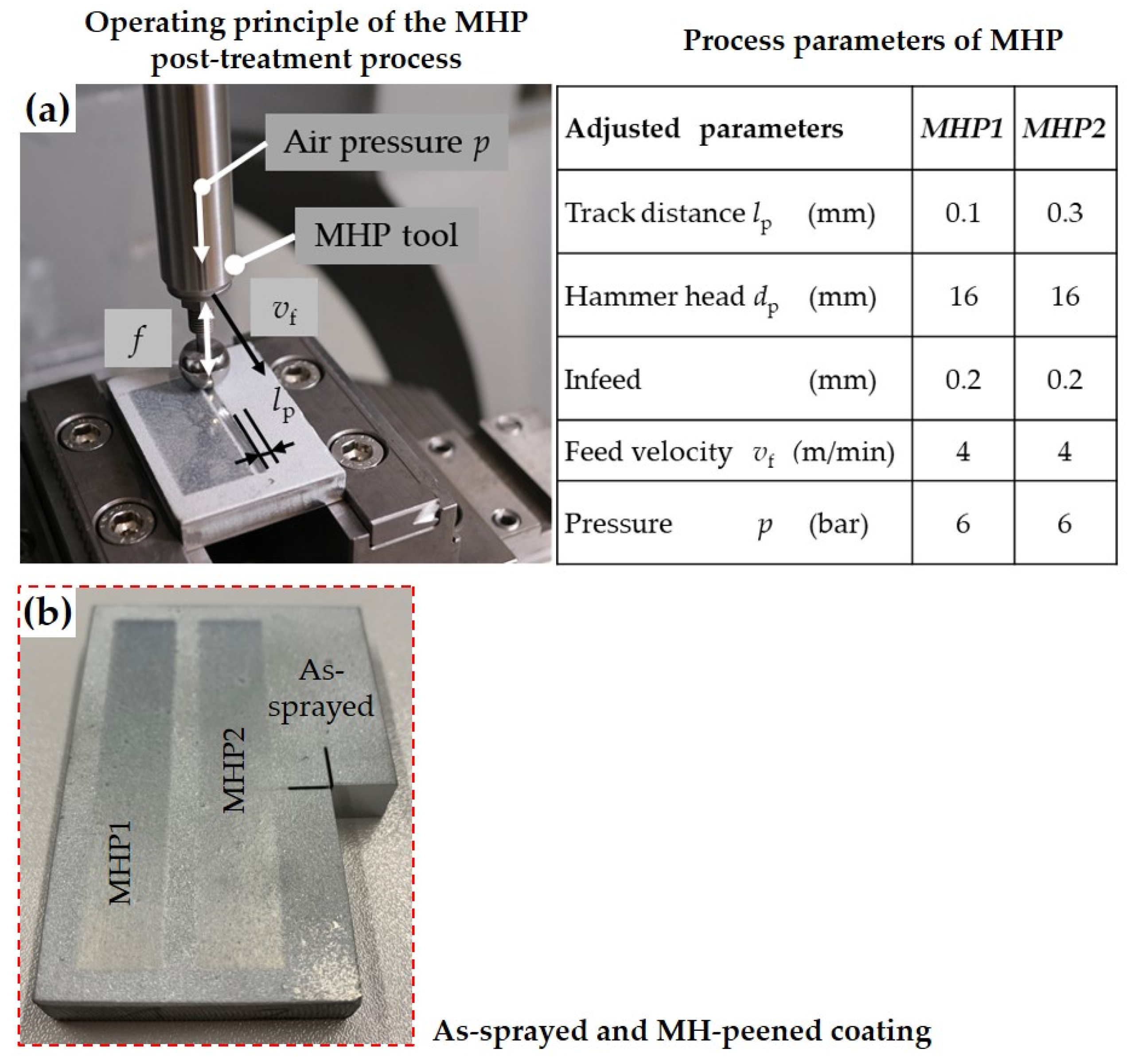
3.3. Effect of the Machine Hammer Peening on the Sprayed Coatings

The surface modification by the MHP process is based on the high impacting forces acting in high frequency on the coating surface. Therefore, MHP as a post-treatment process directly affects the subsurface layers of the post-treated coatings. The plastic deformation of the coating surface asperity led to a smoothing effect and, thus, increased the compressive residual stresses. In thermally sprayed coatings, it is essential to investigate the crack initiation and distribution in the subsurface layers due to the MHP process. These cracks may harm the proper functionality of the post-treated coatings. The variations in the obtained microstructure of the sprayed coatings in this study were not, on average, significant. Therefore, the effect of the MHP post-treatment was almost equal for the coatings sprayed using argon as atomization gas and those sprayed using compressed air. The MHP parameters were kept constant in this study, except the track distance was changed between lp = 0.1 mm for MHP1 and lp = 0.3 mm for MHP2. Decreasing the track distance increases the intensity of plastic deformations and should lead to smoother surfaces.
The adjusted spray parameter values directly affect the surface roughness of the obtained coating, as shown in Figure 11. A comparison was made between the coating with the highest porosity, roughness, and thickness values (A2 and CA2) to show how the MHP affected the microstructure of the treated coatings. Figure 11 shows the surface appearance of the post-treated coatings and the mean roughness depth Rz for argon and compressed sprayed coatings in the as-sprayed conditions and after MHP1 and MHP2 post-treatment. The surface roughness decreased significantly after MH-peening compared to the as-sprayed conditions for both atomization gases. Reducing the track distance led to a smoother surface, as shown in Figure 11. While the decrease in the surface roughness and porosity in the sub-surface was significant for argon and compressed air sprayed coatings, it was moderate for the coating thickness. The compacting effect in the near-surface layers led to a slight increase in the obtained compressive residual stresses for both atomization gases. The roughness values were decreased from 78.9 µm in as-sprayed condition for argon sprayed coatings to 27.6 µm in the case of MHP1 and 37.5 µm for MHP2. In the case of compressed air sprayed coatings, the roughness in the as-sprayed condition was 39.4 µm and, therefore, lower than for Argon. Decreasing the track distance from 0.3 mm in MHP2 to 0.1 mm in MHP1 led to a decrease in the coating roughness from 18.4 to 10.4 µm.
The hardness of compressed air sprayed coatings has increased from the initial 28 HV0.01 in as-sprayed condition to the range between 38.11–49.26 HV0.01 after MHP post-treatment. The achieved increases were in the range between 36% and 76% in this case. Using argon as atomization gas led to softer coating with hardness values of 25.74 HV0.01 in as-sprayed condition and between 33.04 HV0.01 to 38.99 HV0.01 after MHP. The achieved increases here were in the range between 28% and 51%.
In the case of compressed sprayed coatings, the MHP post-treatment has reduced the coating porosity up to 28% compared to the obtained porosity in as-sprayed conditions. The degree of reduction is directly related to the initial coating porosity. Coatings with higher initial porosity have allowed higher porosity reduction after MHP post-treatment for both atomization gases. The porosity level was reduced by 2% to 4% as the track distance decreased from lp = 0.3 mm in MHP2 to lp = 0.1 mm in MHP1. The changes between MHP1 and MHP2 were almost the same for both gases. The use of argon as atomization gas has allowed for even a higher porosity reduction between 18% to 35%. The decline of the coating’s porosity caused by MHP post-treatment is directly associated with the compacting effect. In the case of compressed air sprayed coatings, the reduction in coating thickness has reached values between 8% and 15%. The reduction in the case of argon sprayed coatings was about 7% and 12.57%.
The effect of MHP on the induced compressed residual stresses was insignificant and ranked in the range of the standard deviations of the values obtained in as-sprayed conditions. Figure 12 compares the coatings’ microstructures in as-sprayed and MHP post-treated conditions. The images of compressed air and argon sprayed in Figure 12 have different scales due to the different coating thicknesses obtained using the same spraying parameters. Argon sprayed coatings had a higher coating thickness than coatings produced by using compressed air. A higher horizontal crack tendency was evident in the case of compressed air sprayed coatings. Most of these cracks have occurred at near-surface layers, where the impacting forces of the MHP process were at their highest values.
Upon closer observation of the horizontal cracks, it became clear that the cracks were located in Al-rich zones. The precipitation of Al at and surrounding the Zn-rich lamellae and splats were well illustrated in the SEM images in Figure 6 and Figure 7. The presence of Al in these zones led to the formation of Al-oxide, which is hard and brittle at the same time. The highest amount of Al was found in the crack zone assigned as spectrum 4 in Figure 13. Spectrum 5 and 6 in this figure also indicated a higher amount of Al and Oxygen and are, therefore, locations of possible cracks.
The flow of these cracks was, in most cases, horizontal and pursued the interface between the Al-rich zones and Zn lamellae. The decrease of the track distance in MHP1 led to higher cracking at the near-surface. These cracks changed their direction subsequently at the two ends of the crack towards the coating surface, as shown in Figure 12a MHP1. The cracks were located slightly deeper in MHP2 and parallel the coating surface, as shown in Figure 13.

3.4. Corrosion Behavior of Sprayed and MHP Coatings

TWAS sprayed ZnAl coatings should prevent corrosion and ensure an extended life span of steel structures. Enhancing this behavior through MHP post-treatment is new and thus, it needed to be verified. The combined effect of using TWAS and MHP post-treated ZnAl4 coatings is presented in Figure 14 for both atomization gases. Argon sprayed coatings showed an unfavorable overall corrosion performance compared to the coatings sprayed using compressed air. After 800 h of testing, white corrosion products were more evident in the case of compressed air than in argon sprayed coatings. MHP post-treatment also positively affects corrosion protection, even in highly corrosive maritime environments.
The argon sprayed coatings showed, in as-sprayed conditions, more red corrosion products and coating spalling than the MH peened ones. Small spalling was also evident in the case of compressed air in as-sprayed conditions. Peening with parameter settings MHP1 and MHP2 led to larger spalling areas in the case of argon sprayed coatings. In the case of compressed air sprayed coatings, almost no coating spalling was revealed for the MHP1 and MHP2 post-treated coatings.
Zinc-rich zones possess a lower electrode potential in ZnAl TWAS-sprayed coatings compared to aluminum-rich ones. The active Zn reacted with sodium chloride solution and formed simonkolleite Zn5(OH)8Cl2·H2O as a corrosion product. Compressed air sprayed coatings revealed that the formation of simonkolleite showed higher peaks in MHP2 conditions, as shown in Figure 15a. The further reaction with the electrolyte led to the formation of hydrozincite, zinc oxide, and zinc hydroxide, as shown in Figure 15.
Figure 16 shows the results of the PDP measurements. The current density |i| is plotted over the potential E versus the Ag/AgCl electrode. Two measurements were performed for each tested condition using argon and compressed air. The formation of stable hydroxide and oxide top layers, which are the reason for the improved corrosion resistance in the neutral and weakly alkaline pH range, have a significant influence on the properties of zinc [37]. As Al-containing Zn coatings show lower corrosion resistance under alkaline exposure than pure zinc, partial dissolution of the aluminum components occurs for pH values above 8 [37]. The cathodic branch of the coatings sprayed with argon showed a higher slope than the coatings sprayed with compressed air. Close to the OCP, the anodic branch appears to flatten but reaches a higher slope at higher potentials. As OCP of the compressed air sprayed coatings is higher than with argon sprayed coatings, an improvement of the corrosion performance compared to the argon sprayed coatings can be expected. The improvement can be related to the lower porosity and oxide content in compressed air sprayed coatings.
The EDX spot analyses in Figure 17 were made after an 800 h salt spray corrosion testing of argon and compressed air sprayed coatings. The images revealed cracks and spalling at different locations in the corroded ZnAl coatings produced (a) by using compressed air and (b) using argon. The Al content in the different spectrums ranges from 5 to 8 wt.% in the case of compressed air sprayed coatings and between 3 to 6.5 wt.% by argon sprayed coatings. The content of the Al fraction was almost the same amount as before testing, which means that aluminum is not responsible for crack formation.
The cracks are initiated as an effect of the formation of corrosion products. These reactions led to the formation of the corrosion products mentioned above. The corrosion reactions started directly as the sodium chloride solution came in contact with Zn-rich lamellae or zones. The solution may have penetrated in vertical cracks or pores and reacted with Zn, resulting in corrosion products and embrittlement in Zn-rich lamellae. The required forces for cracking may arise from a volume expansion due to the formation of corrosion products in these cracks, as shown in Figure 18. The volume growth exerted enormous forces on already stressed and embrittled material, which has led to crack propagation in the corroded coatings. Bobzin et al. [38] found no corrosion cracks in pure zinc coatings, which may lead to the assumption that the Zn functioned in two phases, Zn and Al coatings as a sacrificial anode in the 5% sodium chloride solution.

4. Discussion and Conclusions

A significant difference in the effect of the spraying process parameters on the obtained coating microstructure was revealed between the argon and the compressed air sprayed coatings. The different ionization energy and density of the used atomization gases are the reasons for the obtained changes. The low melting point of ZnAl4 made this feedstock material very sensitive to the variation in the TWAS process parameter adjusted. The heat input in the arc zone is directly affected by the used atomization gas [13,21,27]. The different ionization energy between argon and compressed air and the higher density of argon affected the melting behavior and coating microstructure of ZnAl4 coatings directly. The used atomization gas also controlled the effect of the process parameter values on the obtained coatings. The effect of the wire feed rate on the obtained porosity, e.g., was negative in the case of compressed air and positive by argon, which can be explained by the higher ionization energy of argon and, thus, higher arc temperatures. The higher arc temperatures allow for the atomization of larger particles out of the molten part in the intersecting wires, leading to increased porosity levels in the obtained coatings. The atomization of larger particles also led to a higher coating roughness in the case of argon sprayed coatings. The slightly higher compressive residual stresses in argon sprayed coatings can also be explained by the higher ionization energy and density of argon.
The apparent differences between compressed air and argon sprayed coatings are directly related to the different temperatures at which the impacting particles start to solidify. A closer look at the obtained coating microstructures revealed a eutectic composition, especially in the case of compressed air sprayed coatings. The images of the melted wires in Figure 5 indicate two types of particle initiation by spraying ZnAl4 feedstock wires.
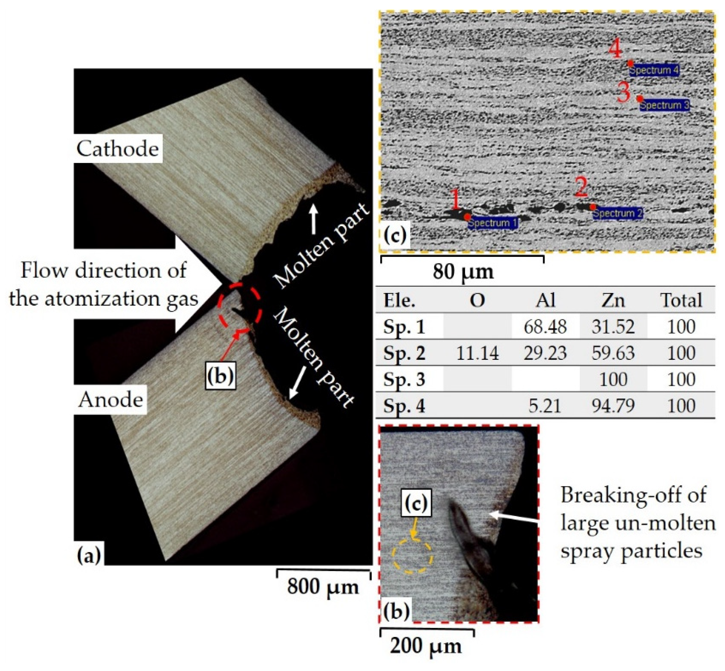
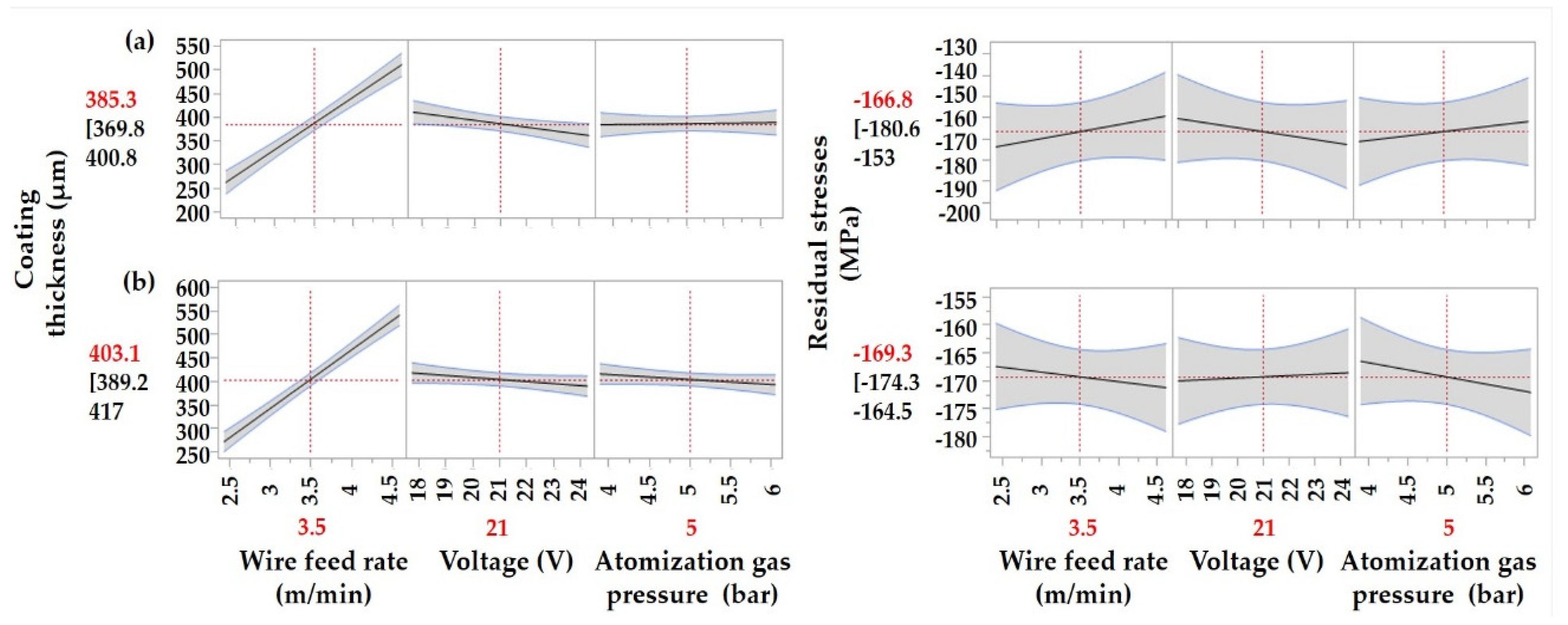
  • These are the atomization of the molten part at the tips of the approaching wires and breaking-off of large metal detachments. Compressive residual stresses in as-sprayed conditions indicate that a high number of the spray particles are initiated by breaking-off of large metal detachments. This explains that against all expectations, the residual stresses in the TWAS sprayed coatings for both gases were compressive. This abnormality is due to the higher kinetic energy of the impacting particles, “large metal detachments,” compared to the thermal ones. The ripped particles have higher impact energy and explain the obtained compressive residual stress in ZnAl4 TWAS sprayed coatings. The MHP post-treatment of the obtained coatings led to a slight increase in the induced compressive residual stresses.
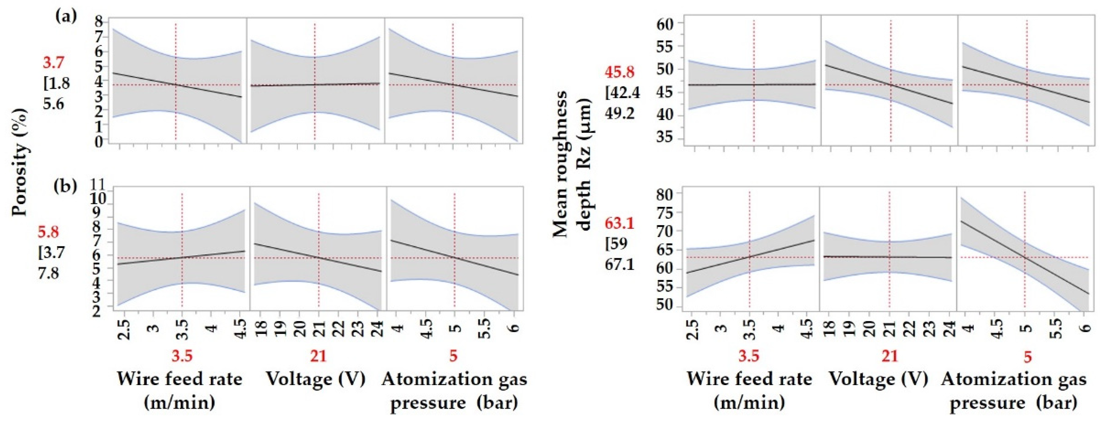
  • Moreover, this type of particle detachment elucidates the low oxide content in compressed air sprayed coatings. Interestingly, the argon sprayed coatings revealed a higher oxide content than its counterpart, which declares that the oxidation of spraying particles has occurred during their in-flight phase or while impacting on the substrate surface rather than at their atomization stage. Argon as atomization gas led to coatings with higher thickness, surface roughness, and porosity.
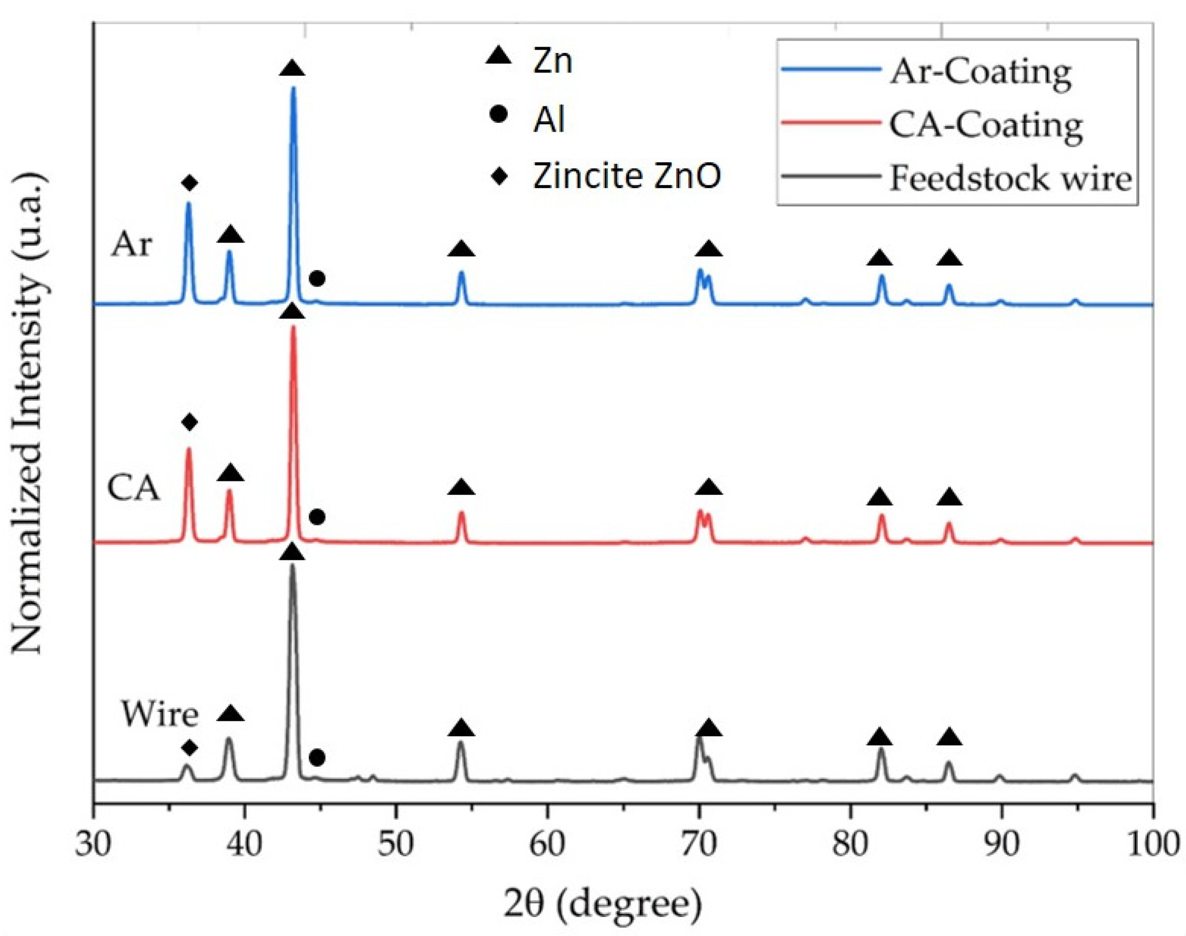
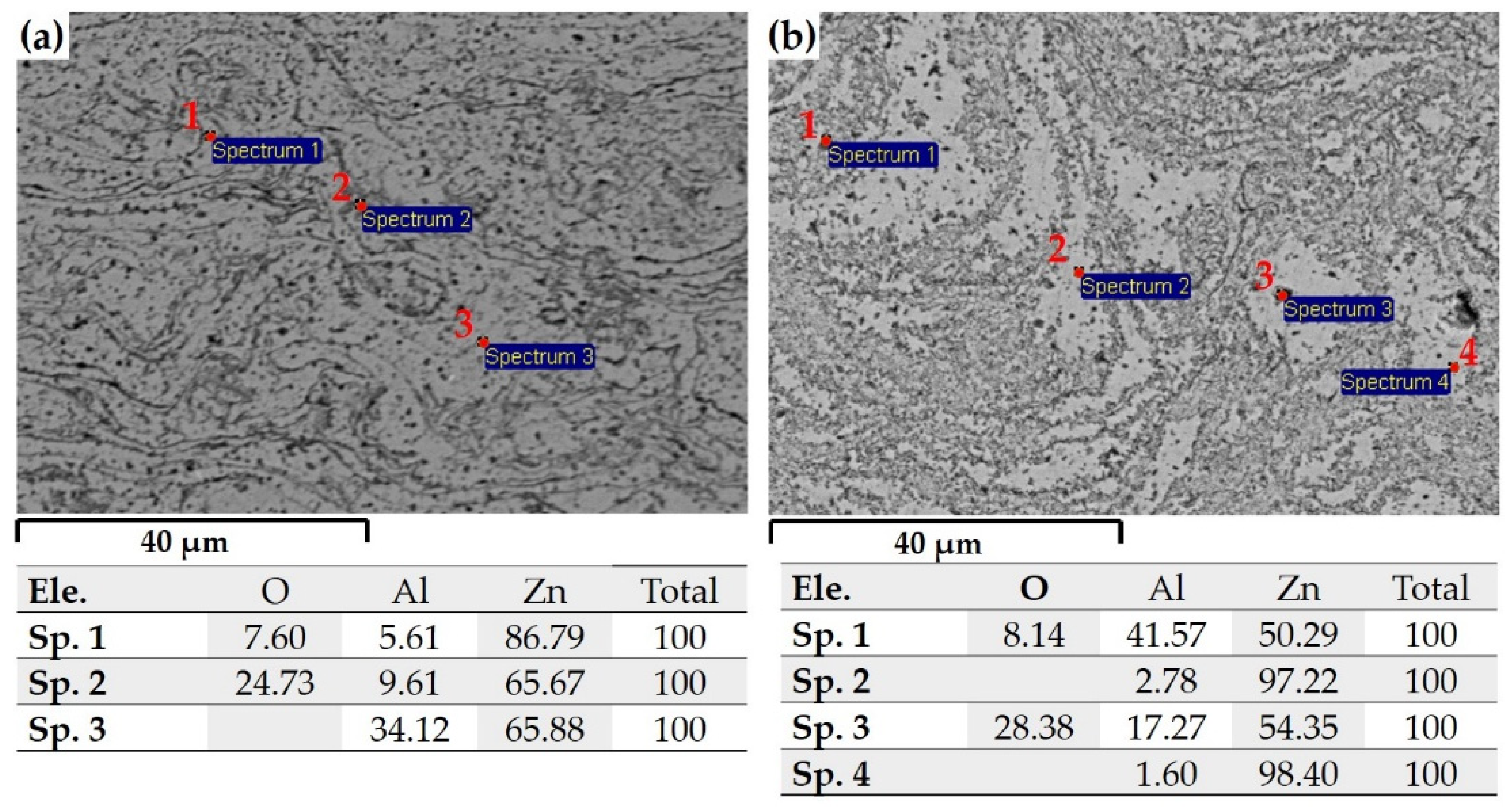
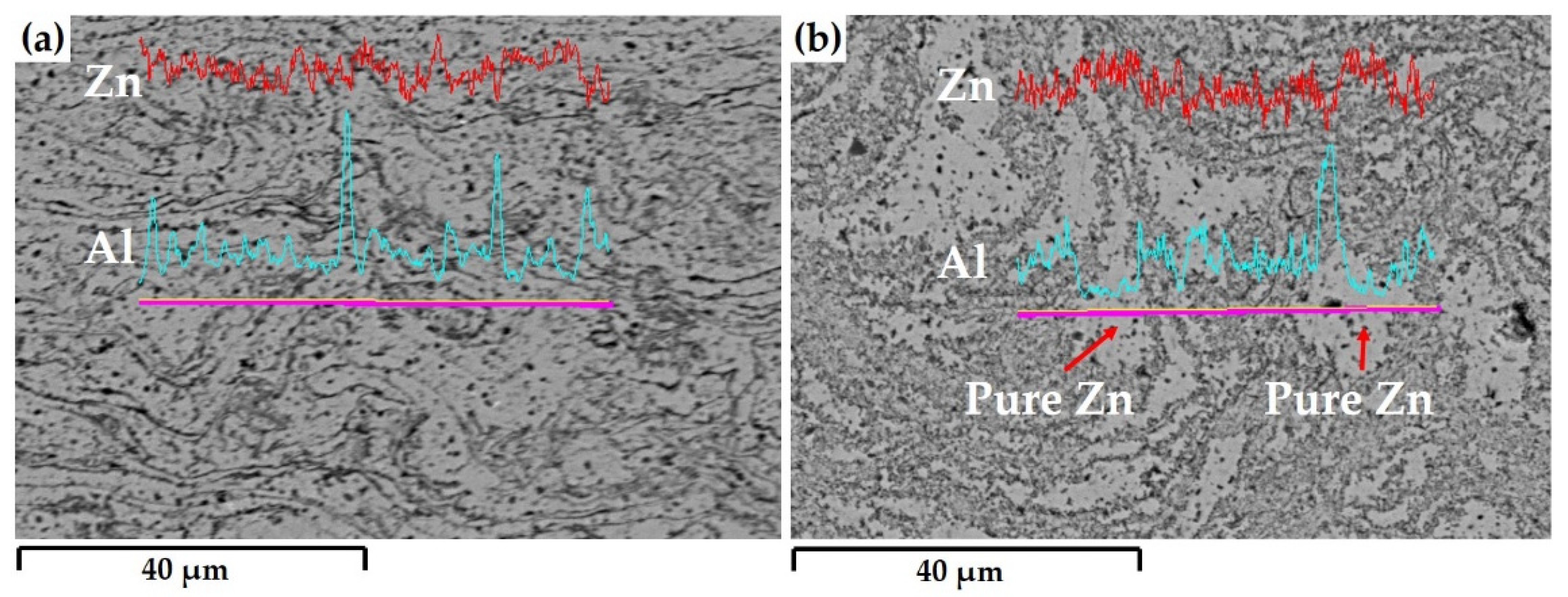
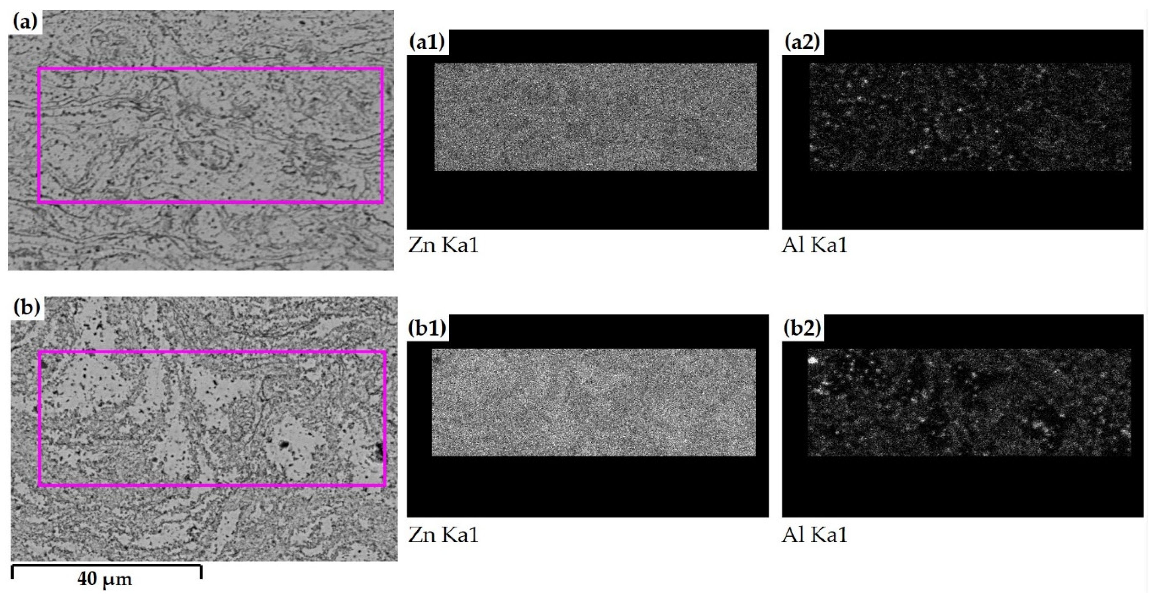
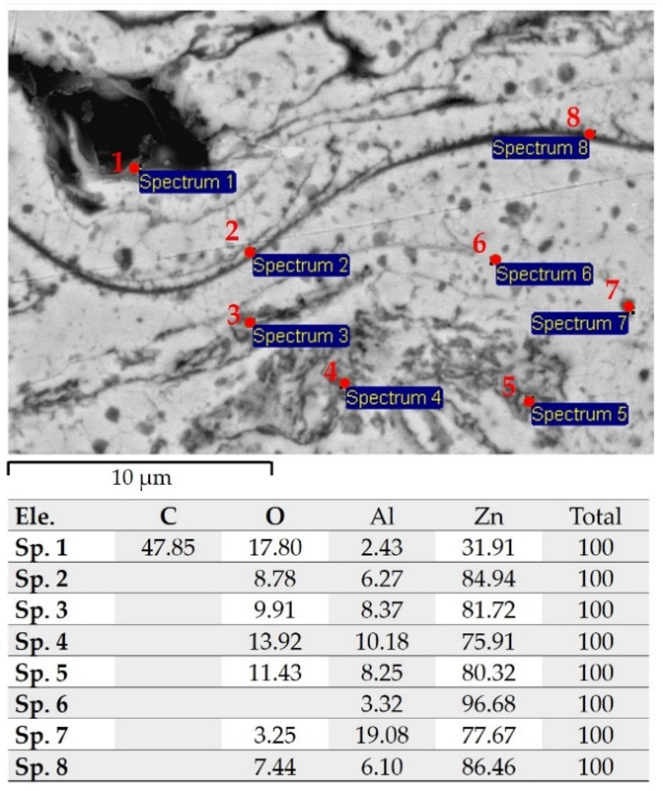
  • The differences in the nucleation of Zn and precipitation of Al indicate the difference in the temperature of the impacting particles between argon and compressed air sprayed coatings. Zinc-rich phases were nucleated by compressed air sprayed coatings in the form of several splats connected as thin layers. These layers are surrounded by a dense network of tiny strip-like constructs of precipitated Al-rich-phase. The precipitation of the Al-rich-phase has occurred in larger particles unevenly distributed around relatively pure Zn nucleation. These differences directly affected the MHP post-treatment process and corrosion performance.
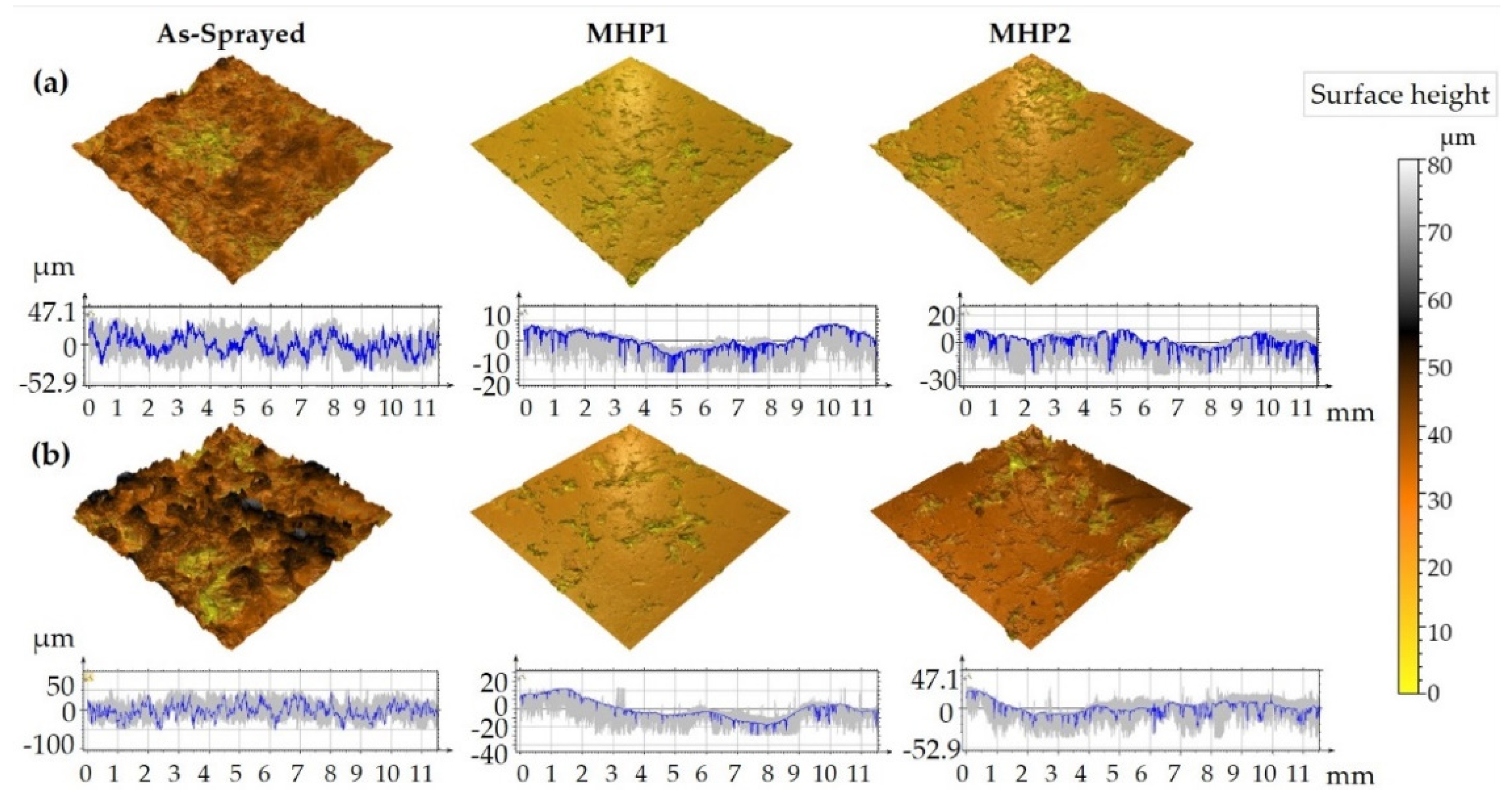
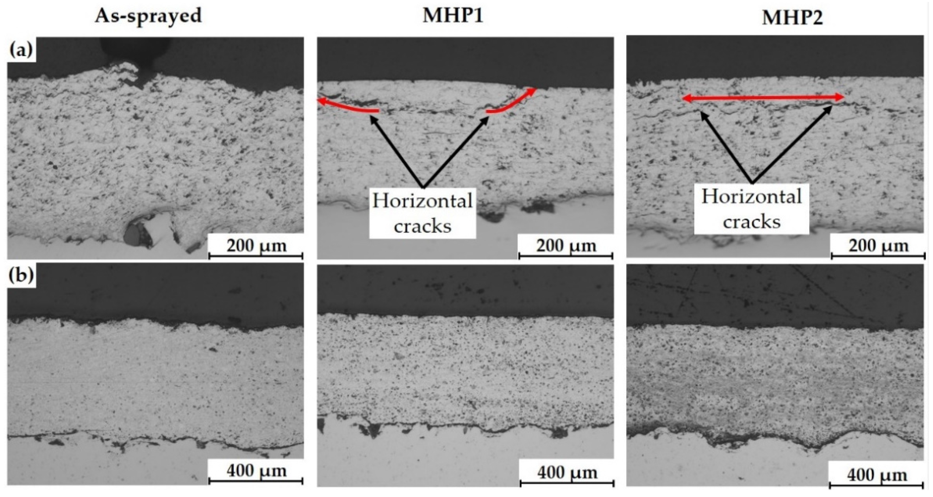
  • MHP as a post-treatment technique led to a decrease in coating porosity, roughness, and thickness by compressed air and argon sprayed coatings. The decrease is directly related to the initial microstructure of the post-treated coatings. In the case of compressed air sprayed coatings, the network of tiny strip-like constructs of precipitated Al-rich-phase tended to form Al-oxide, which directly affects the crack formation during MHP treatment. The crack location and orientation were also affected by the track distance of the MHP process. Intensive cracking has occurred at a lower track distance, which intersected the treated surface at both ends of the crack. Argon sprayed coatings showed a lower cracking tendency during MHP post-treatment, which can be explained by the lower hardness of argon sprayed coatings.
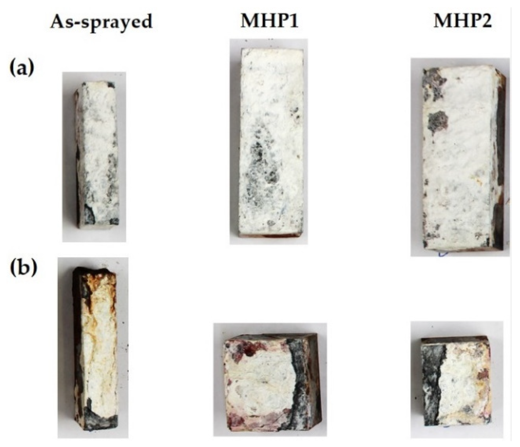
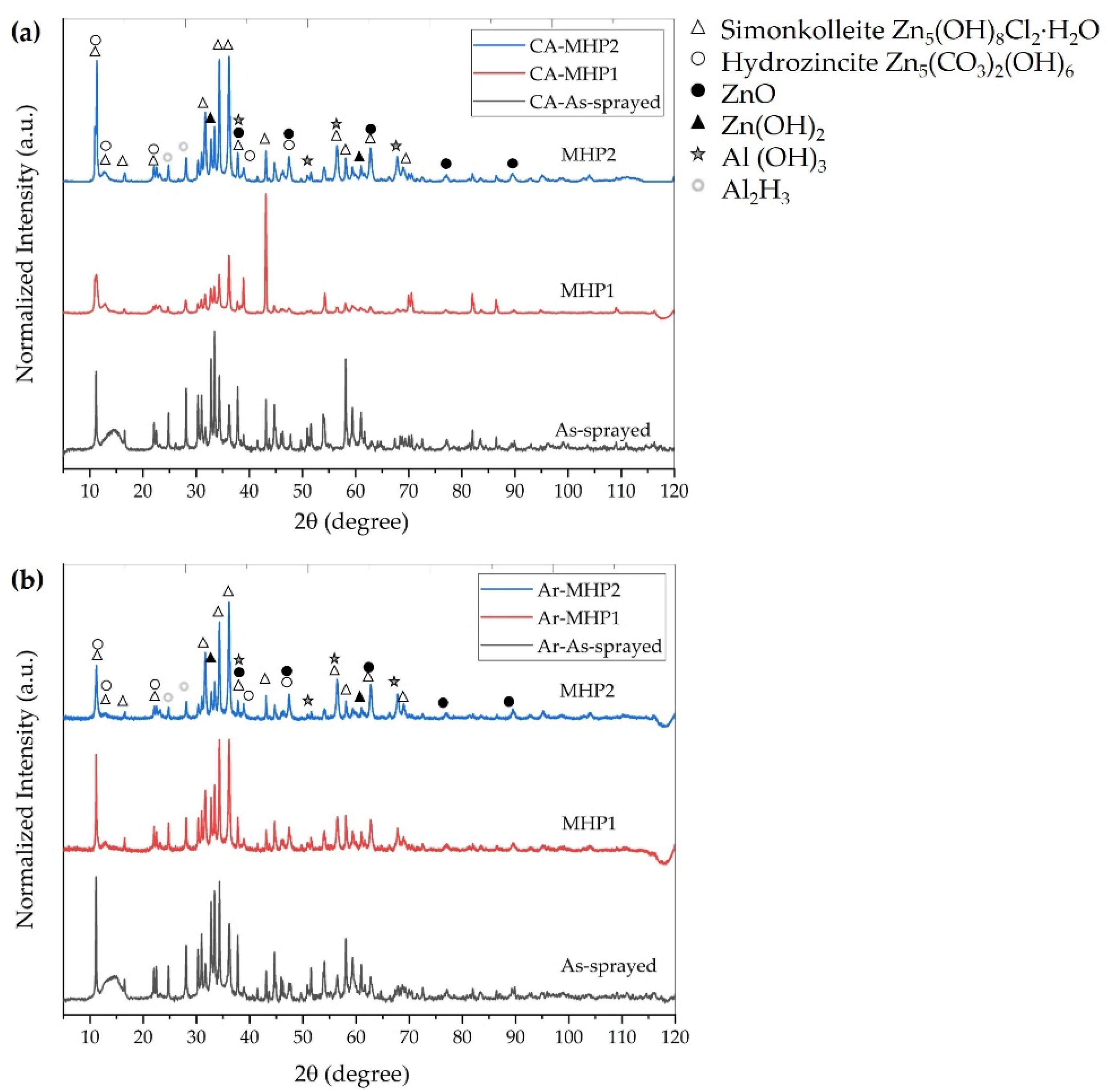
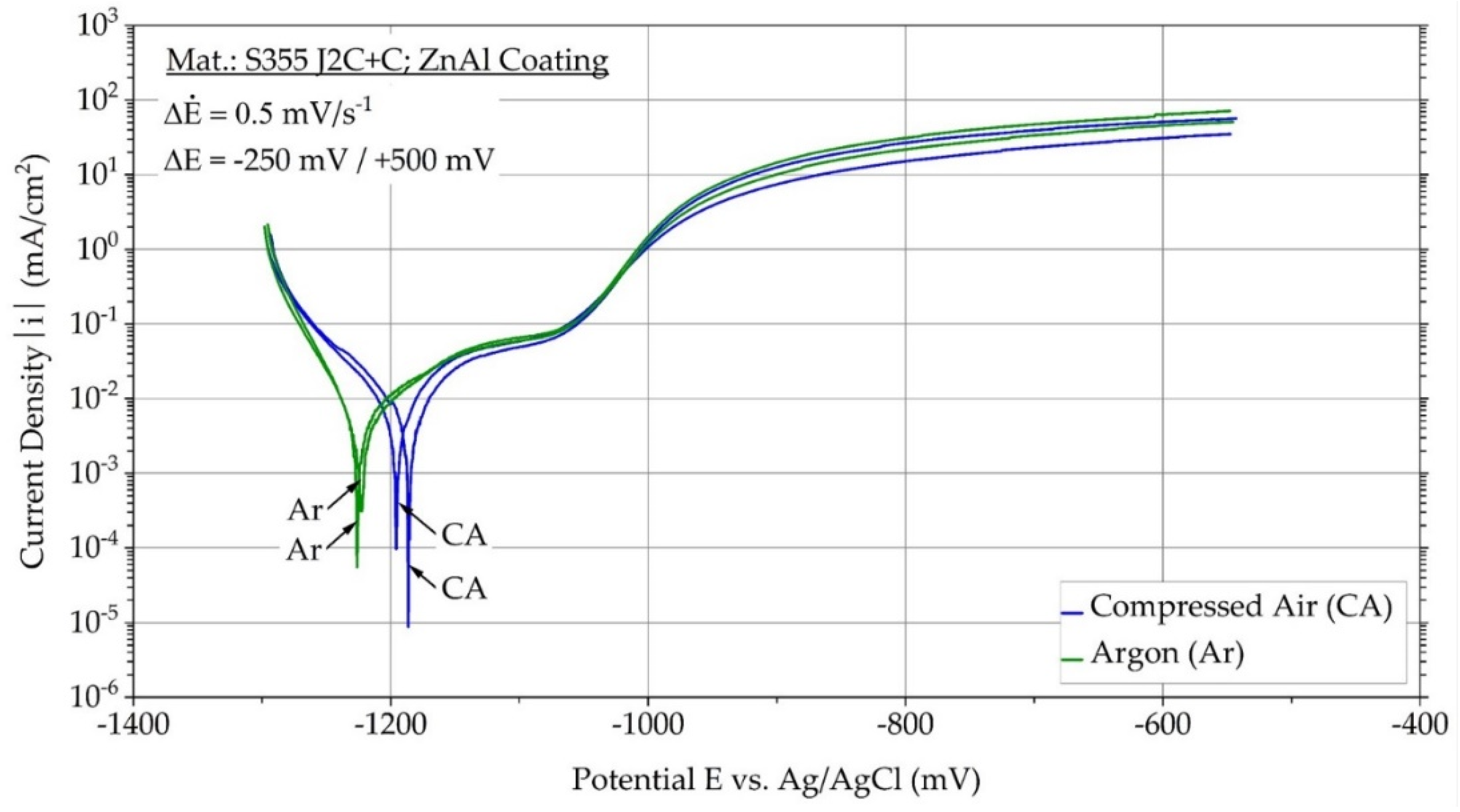
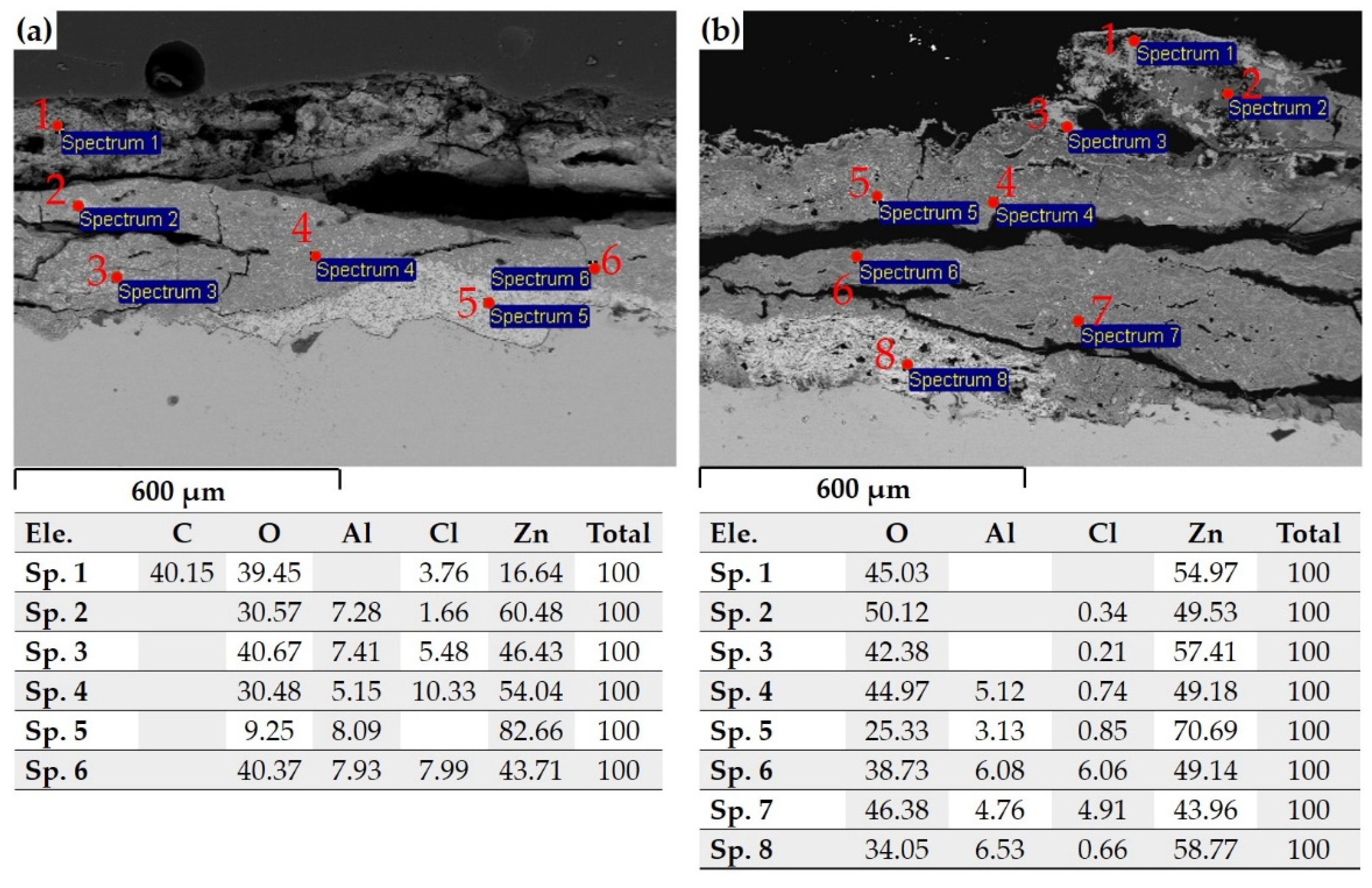
  • The better corrosion performance of compressed air sprayed coatings can be explained by their higher formation of simonkolleite, which exhibits a better barrier function concerning oxygen diffusion than most other corrosion products [38,39,40,41] and may improve the corrosion resistance. The use of argon as atomization gas showed a unfavorable corrosion performance in 5% NaCl solution. This reason is believed to be the clear separation between almost pure Zn phases and Al-rich-phases. The Zn has functioned in this two-phase compound as a sacrificial anode in the surrounding electrolyte and was consumed to form brittle corrosion products and generate a network of vertical and horizontal cracks. Even though the sprayed argon possessed a higher coating thickness than compressed air sprayed coatings, they were entirely consumed during the corrosion test, and red corrosion products started to form. MHP post-treatment has improved the corrosion performance for both atomization gases.
Further investigations are required to enlighten the actual melting behavior of the low melting ZnAl-based wires. In particular, the effect of excessive Zn-dust formation on the spraying process and how to control it. The improvement may lead to a higher deposition rate and better coating quality.

Author Contributions

Conceptualization, W.T., M.A., A.W., M.P.M., D.B. and F.W.; methodology, M.A.; software, M.A.; validation, M.A.; formal analysis, M.A.; investigation, M.A., A.W. and M.P.M.; resources, W.T., D.B. and F.W.; data curation, M.A.; writing—original draft preparation, M.A.; writing—review and editing, M.A., A.W., M.P.M., W.T., D.B. and F.W.; visualization, M.A.; supervision, W.T., D.B. and F.W.; project administration, W.T., D.B. and F.W.; funding acquisition, W.T., D.B. and F.W. All authors have read and agreed to the published version of the manuscript.

Funding

Funded by the Deutsche Forschungsgemeinschaft (DFG, German Research Foundation)—Project No. 426365081 “Process parameters correlated characterization of the corrosion fatigue behavior of post-treated ZnAl-coated arc-sprayed systems”.

Institutional Review Board Statement

Not applicable.

Informed Consent Statement

Not applicable.

Data Availability Statement

Not applicable.

Acknowledgments

We acknowledge financial support by Deutsche Forschungsgemeinschaft and Technische Universität Dortmund/TU Dortmund University within the funding program Open Access Publishing.

Conflicts of Interest

The authors declare no conflict of interest.

References

  1. Fauchais, P.L.; Heberlein, J.V.; Boulos, M.I. Thermal Spray Fundamentals: From Powder to Part; Springer Science & Business Media: Boston, MA, USA, 2014; pp. 17–72. [Google Scholar]
  2. Newbery, A.P.; Grant, P.S. Large arc voltage fluctuations and droplet formation in electric arc wire spraying. Powder Met. 2003, 46, 229–235. [Google Scholar] [CrossRef]
  3. Pourmousa Abkenar, A. Wire-Arc Spraying System: Particle Production, Transport, and Deposition; Library and Archives Canada Bibliothèque et Archives Canada: Ottawa, ON, Canada, 2009. [Google Scholar]
  4. Bolot, R.; Planche, M.-P.; Liao, H.; Coddet, C. A three-dimensional model of the wire-arc spray process and its experimental validation. J. Mater. Process. Technol. 2008, 200, 94–105. [Google Scholar] [CrossRef]
  5. Watanabe, T.; Wang, X.; Pfender, E.; Heberlein, J. Correlations between electrode phenomena and coating properties in wire arc spraying. Thin Solid Films 1998, 316, 169–173. [Google Scholar] [CrossRef]
  6. Gedzevicius, I.; Valiulis, A. Analysis of wire arc spraying process variables on coatings properties. J. Mater. Process. Technol. 2006, 175, 206–211. [Google Scholar] [CrossRef]
  7. Tillmann, W.; Abdulgader, M. Wire composition: Its effect on metal disintegration and particle formation in twin-wire arc-spraying process. J. Therm. Spray Technol. 2013, 22, 352–362. [Google Scholar] [CrossRef]
  8. Wang, X.; Heberlein, J.; Pfender, E.; Gerberich, W. Effect of nozzle configuration, gas pressure, and gas type on coating properties in wire arc spray. J. Therm. Spray Technol. 1999, 8, 565–575. [Google Scholar] [CrossRef]
  9. Gedzevičius, I.; Valiulis, A.V. Influence of the particles velocity on the arc spraying coating adhesion. Matrix 2003, 1, 334–337. [Google Scholar]
  10. Zeng, Z.; Sakoda, N.; Tajiri, T. Corrosion behavior of wire-arc-sprayed stainless steel coating on mild steel. J. Therm. Spray Technol. 2006, 15, 431–437. [Google Scholar] [CrossRef]
  11. Newbery, A.P.; Grant, P.S. Arc Sprayed Steel: Microstructure in severe substrate features. J. Therm. Spray Technol. 2009, 18, 256–271. [Google Scholar] [CrossRef]
  12. Newbery, A.; Grant, P. Oxidation during electric arc spray forming of steel. J. Mater. Process. Technol. 2006, 178, 259–269. [Google Scholar] [CrossRef]
  13. Planche, M.; Liao, H.; Coddet, C. Relationships between in-flight particle characteristics and coating microstructure with a twin wire arc spray process and different working conditions. Surf. Coatings Technol. 2004, 182, 215–226. [Google Scholar] [CrossRef]
  14. Tillmann, W.; Abdulgader, M.; Pohl, M.; Baak, J. Einfluss des spritzabstands zwischen shroud-austritt und substratoberfläche auf das pseudoelastische verhalten von niti-lichtbogengespritzten schichten. Therm. Spray Bull. 2018, 1, 32–37. [Google Scholar]
  15. Sacriste, D.; Goubot, N.; Dhers, J.; Ducos, M.; Vardelle, A. An Evaluation of the electric arc spray and (HPPS) processes for the manufacturing of high power plasma spraying MCrAlY Coatings. J. Therm. Spray Technol. 2001, 10, 352–358. [Google Scholar] [CrossRef]
  16. Jandin, G.; Liao, H.; Feng, Z.; Coddet, C. Correlations between operating conditions, microstructure and mechanical properties of twin wire arc sprayed steel coatings. Mater. Sci. Eng. A Struct. Mater. Prop. Microstruct. Process. 2003, 349, 298–305. [Google Scholar] [CrossRef] [Green Version]
  17. Hussary, N.; Heberlein, J. Effects of metal atomization, arc and pressure fluctuations on the final particle size distribution in the wire arc spraying process. In Proceedings of the 30th International Conference on Plasma Science, Jeju, Korea, 2–5 June 2003; p. 362. [Google Scholar] [CrossRef]
  18. Zhao, L.; Fu, B.; He, D.; Kutschmann, P. Development of a new wear resistant coating by arc spraying of a steel-based cored wire. Front. Mech. Eng. China 2009, 4, 1–4. [Google Scholar] [CrossRef]
  19. Santana, Y.; Renault, P.; Sebastiani, M.; La Barbera, J.; Lesage, J.; Bemporad, E.; Le Bourhis, E.; Puchi-Cabrera, E.; Staia, M. Characterization and residual stresses of WC–Co thermally sprayed coatings. Surf. Coatings Technol. 2008, 202, 4560–4565. [Google Scholar] [CrossRef]
  20. Reuss, G. Beitrag zur Überwachung des thermischen Spritzprozesses mittels Schallemissionsanalyse (SEA). Ph.D. Thesis, Universität Dortmund, Dortmund, Germany, 2001. [Google Scholar] [CrossRef]
  21. Hasan, M.; Stokes, J.; Looney, L.; Hashmi, M.S.J. Deposition and characterization of hvof thermal sprayed functionally graded coatings deposited onto a lightweight material. J. Mater. Eng. Perform. 2009, 18, 66–69. [Google Scholar] [CrossRef]
  22. Junior, G.; Voorwald, H.; Vieira, L.; Cioffi, M.; Bonora, R. Evaluation of WC-10Ni thermal spray coating with shot peening on the fatigue strength of AISI 4340 steel. Procedia Eng. 2010, 2, 649–656. [Google Scholar] [CrossRef] [Green Version]
  23. Rodriguez, A.; De Lacalle, L.N.L.; Pereira, O.; Fernandez, A.; Ayesta, I. Isotropic finishing of austempered iron casting cylindrical parts by roller burnishing. Int. J. Adv. Manuf. Technol. 2020, 110, 1–9. [Google Scholar] [CrossRef] [PubMed]
  24. Egea, A.S.; Rodríguez, A.; Celentano, D.; Calleja, A.; de Lacalle, L.L. Joining metrics enhancement when combining FSW and ball-burnishing in a 2050 aluminium alloy. Surf. Coatings Technol. 2019, 367, 327–335. [Google Scholar] [CrossRef] [Green Version]
  25. Adjassoho, B.; Kozeschnik, E.; Lechner, C.; Bleicher, F.; Goessinger, S.; Bauer, C. Induction of residual stresses and increase of surface hardness by machine hammer peening technology. In Annals of DAAAM for 2012, Proceedings of the 23rd International DAAAM Symposium, Zadar, Croatia, 24–27 October 2012; DAAAM: Vienna, Austria, 2012; pp. 1382–2304. [Google Scholar]
  26. Groche, P.; Engels, M.; Steitz, M.; Müller, C.; Scheil, J.; Heilmaier, M. Potential of mechanical surface treatment for mould and die production. Int. J. Mater. Res. 2012, 103, 783–789. [Google Scholar] [CrossRef]
  27. Hacini, L.; Van Lê, N.; Bocher, P. Effect of impact energy on residual stresses induced by hammer peening of 304L plates. J. Mater. Process. Technol. 2008, 208, 542–548. [Google Scholar] [CrossRef]
  28. Bleicher, F.; Lechner, C.; Habersohn, C.; Kozeschnik, E.; Adjassoho, B.; Kaminski, H. Mechanism of surface modification using machine hammer peening technology. CIRP Ann. 2012, 61, 375–378. [Google Scholar] [CrossRef]
  29. Steitz, M.; Scheil, J.; Müller, C.; Groche, P. Effect of process parameters on surface roughness in hammer peening and deep rolling. Key Eng. Mater. 2013, 554, 1887–1901. [Google Scholar] [CrossRef]
  30. Rausch, S.; Wiederkehr, P.; Biermann, D.; Zabel, A.; Selvadurai, U.; Hagen, L.; Tillmann, W. Influence of machine hammer peening on the tribological behavior and the residual stresses of wear resistant thermally sprayed coatings. Procedia CIRP 2016, 45, 275–278. [Google Scholar] [CrossRef] [Green Version]
  31. Adjassoho, B.; Kozeschnik, E.; Lechner, C.; Habersohn, C.; Bleicher, F.; Gössinger, S.; RIPOLL, M.R. Controlled surface treatment with machine hammer peening. In Proceedings of the 22nd International Conference on Metallurgy and Materials, Brno, Czech Republic, 22–24 May 2013. [Google Scholar]
  32. Pradhan, D.; Mahobia, G.S.; Chattopadhyay, K.; Singh, V. Effect of surface roughness on corrosion behavior of the superalloy IN718 in simulated marine environment. J. Alloy. Compd. 2018, 740, 250–263. [Google Scholar] [CrossRef]
  33. Timmermann, A.; Abdulgader, M.; Hagen, L.; Koch, A.; Wittke, P.; Biermann, D.; Tillmann, W.; Walther, F. Effect of machine hammer peening on the surface integrity of a ZnAl-based corrosion protective coating. MATEC Web Conf. 2020, 318, 01008. [Google Scholar] [CrossRef]
  34. Noyan, I.C.; Cohen, J.B. Residual Stress: Measurement by Diffraction and Interpretation; Springer: New York, NY, USA, 2013; pp. 47–229. [Google Scholar]
  35. Hauk, V. Structural and Residual Stress Analysis by Nondestructive Method; Elsevier Science: Amsterdam, The Netherlands, 1997; pp. 17–494. [Google Scholar]
  36. Wei, X.; Ren, L.; Geng, X.; Sun, Z.; Hu, H.; Nie, X.; Banerji, A. Nano microstructure development and solidification of Zn-6 wt% Al hypereutectic alloy. Mater. Charact. 2018, 147, 295–302. [Google Scholar] [CrossRef]
  37. Kunze, E. Korrosion und Korrosionsschutz, Band 2: Korrosion der Verschiedenen Werkstoffe; WILEY-VCH Verlag GmbH & Co. KGaA: Weinheim, Germany, 2001. [Google Scholar]
  38. Bobzin, K.; Öte, M.; Knoch, M.A. Corrosion behaviour of thermally sprayed Zn, ZnMgAl and ZnAl15 coatings. In Proceedings of the EUROCORR 2017– The Annual Congress of the European Federation of Corrosion, 20th International Corrosion Congress and Process Safety Congress, Prague, Czech Republic, 3–7 September 2017. [Google Scholar]
  39. Volovitch, P.; Allely, C.; Ogle, K. Understanding corrosion via corrosion product characterization: I. Case study of the role of Mg alloying in Zn–Mg coating on steel. Corros. Sci. 2009, 51, 1251–1262. [Google Scholar] [CrossRef]
  40. Volovitch, P.; Vu, T.N.; Allély, C.; Aal, A.A.; Ogle, K. Understanding corrosion via corrosion product characterization: II. Role of alloying elements in improving the corrosion resistance of Zn–Al–Mg coatings on steel. Corros. Sci. 2011, 53, 2437–2445. [Google Scholar] [CrossRef]
  41. Yung, T.-Y.; Chen, T.-C.; Tsai, K.-C.; Lu, W.-F.; Huang, J.-Y.; Liu, T.-Y. Thermal spray coatings of Al, ZnAl and inconel 625 alloys on SS304L for anti-saline corrosion. Coatings 2019, 9, 32. [Google Scholar] [CrossRef] [Green Version]
Figure 1. Machine hammer peening (MHP) post-treatment and the adjusted process parameters. (a) pictorial schematic of MHP process, (b) MH-peened specimen.
Coatings 12 00032 g001
Figure 2. X-ray diffraction pattern of ZnAl4, as wires, sprayed coating using compressed air (CA), and argon (Ar).
Coatings 12 00032 g002
Figure 3. SEM micrographs of ZnAl4 coatings with EDX area scans and element concentration (a) using compressed air and (b) using argon as atomization gas.
Coatings 12 00032 g003
Figure 4. Phase diagram of binary Zn–Al alloy [36] modified through adding a shaded area.
Coatings 12 00032 g004
Figure 5. Melting behavior and microstructure of the feedstock ZnAl4 wires, (a) light microscopy image resemble the configuration of the intersecting wires in the TWAS process, (b) SEM image of possible detachment zone of large ruptures, and (c) point analyses of the sprayed wires.
Coatings 12 00032 g005
Figure 6. EDX spot analyses of the coating microstructure; (a) compressed air sprayed coating and (b) argon sprayed coating.
Coatings 12 00032 g006
Figure 7. EDX line analyses of the coating microstructure; (a) compressed air sprayed coating and (b) argon sprayed coating.
Coatings 12 00032 g007
Figure 8. EDX analyses showing smart-maps of the element distribution of Zn and Al for (a) compressed air sprayed coating, (a1) Zn distribution and (a2) Al distribution; (b) argon sprayed coating, (b1) Zn distribution, and (b2) Zinc distribution.
Coatings 12 00032 g008
Figure 9. The effect of the process parameters on coating porosity and roughness (a) of compressed air sprayed coatings and (b) of argon sprayed coatings.
Coatings 12 00032 g009
Figure 10. The effect of the process parameters on coating thickness and induced residual stresses (a) of compressed air sprayed coatings, (b) of argon sprayed coatings.
Coatings 12 00032 g010
Figure 11. Surface roughness of the as-sprayed condition and after the MHP-treatment: (a) compressed air sprayed coating (CA2) and (b) argon sprayed coating (A2).
Coatings 12 00032 g011
Figure 12. Machine hammer peening effect on the coating microstructure: (a) compressed air sprayed coatings and (b) argon sprayed coatings.
Coatings 12 00032 g012
Figure 13. SEM images of the crack zones in near-surface zones of MHP post-treated coatings produced by using compressed air as atomization gas.
Coatings 12 00032 g013
Figure 14. White corrosion products of ZnAl4 TWAS sprayed coatings: (a) using compressed air and (b) using argon as atomization gas.
Coatings 12 00032 g014
Figure 15. XRD patterns of the Zn–Al diffusion layer corrosion products during salt spray corrosion test after 800 h of (a) compressed air sprayed coatings and (b) argon sprayed coatings.
Coatings 12 00032 g015
Figure 16. Potentiodynamic polarization curves of argon and compressed air sprayed coatings in as-sprayed conditions.
Coatings 12 00032 g016
Figure 17. SEM-images of corroded coatings: (a) in compressed air sprayed coatings and (b) in argon sprayed coatings.
Coatings 12 00032 g017
Figure 18. Crack initiation and growth in a corroded ZnAl coating.
Coatings 12 00032 g018
Table 1. Chemical composition of the substrate material S355 J2 plus N according to the material data sheet of the manufacturer (ThyssenKrupp Schulte GmbH, Dortmund, Germany).
ElementFeCSiMnPSCu
wt.%bal.0.200.551.600.0250.0250.55
Table 2. Chemical composition of the wires according to the material data sheet of the manufacturer (Grillo-Werke AG, Duisburg, Germany).
ElementZnAlSiFePbCuSn
Wt.%bal.3.5–4.5≤0.03≤0.005≤0.003≤0.002≤0.001
Table 3. Full-factorial plan for the TWAS process; parameters: wire feed rate (2.5, 3.5, 4.5 m/min), voltage (18, 21, 24 V), atomization gas pressure (4, 5, 6 bar), (CA compressed air).
Design PatternExperimental NumberingWire Feed RateVoltageAtom. Gas Pressure
ArgonCAm/minVbar
−−+A1CA12.5186+
+−−A2CA24.5+24+4
000A3CA33.5021050
+−−A4CA44.5+184
−++A5CA52.524+6+
000A6CA63.5021050
−+−A7CA72.524+4
+−+A8CA84.5+186+
++−A9CA94.5+24+6+
−−−A10CA102.5184
Publisher’s Note: MDPI stays neutral with regard to jurisdictional claims in published maps and institutional affiliations.

