Article

Expression of the Self-Sharpening Mechanism of a Roller Cone Bit during Wear Due to the Influence of the Erosion Protection Carbide Coating

1
Department of Geotechnology, Mining and Environment, Faculty of Natural Sciences and Engineering, University of Ljubljana, Aškerčeva 12, 1000 Ljubljana, Slovenia
2
Department of Materials and Metallurgy, Faculty of Natural Sciences and Engineering, University of Ljubljana, Aškerčeva 12, 1000 Ljubljana, Slovenia
*
Author to whom correspondence should be addressed.
Coatings 2021, 11(11), 1308; https://doi.org/10.3390/coatings11111308
Submission received: 30 September 2021 / Revised: 25 October 2021 / Accepted: 26 October 2021 / Published: 28 October 2021

Abstract

:
Roller cone drill bits are used in drilling larger diameter wells. The drilling efficiency of the roller cone drill bit depends on the wear rate of the materials that forms bit teeth, which crushes the rock at the bottom of the well. To prevent excessive wear, research has largely focused on the study and determination of abrasion-resistant materials. In our work, we investigated the wear mechanism of a roller cone drill bit whose wear-resistant teeth are protected by a hard metal coating welded onto the teeth. The difference between material properties of erosion-protective carbide coating and the tooth steel leads to uneven wear of bit teeth. In order to determine the material changes, we carried out detailed studies of the rock through which drilling was carried out, the drilling parameters and the materials of which the roller cone bit is made. The principle of wear of the tooth materials and their carbide coating, determined by our research, indicated the guidelines which could be basis for the development of abrasion-resistant materials could be carried out, as well as the problem of applying an erosion protection to the teeth of the studied type of roller cone bits.

1. Introduction

The effective life of a roller cone bit depends largely on the material properties of bit. Drilling efficiency decreases due to the effects of drilling regime, properties of the rock through which we are drilling, through and the wear of the bit.
In our research we focused on the issue of wear resistance of the material of the roller cone bit, which is a consequence of the action of forces and erosive influence of rock particles in the drilling fluid (mud).
We studied the so-called self-sharpening mechanism of the roller cone bit teeth wear, which is expressed in the case when the teeth of the bit are protected from wear on one side by a carbide coating. In this case, the sides of the teeth that are unprotected by a wear-reducing coating wear out faster than the sides of the teeth that are protected by a resistant coating. Wear on the sides of the teeth that are not protected by the carbide coating changes the geometry of the teeth, which slightly reduces the drilling efficiency of the roller cone bit. However, such a worn bit is effective longer than in the case without carbide coating.
In the studies to characterise the wear of the roller cone bit, we thoroughly investigated the rock drilled through, the drilling parameters, and the materials that make up the bit. Based on the knowledge gained from the investigations, the importance of a high-quality erosion protection coating made of carbide for the development and wear rate of the roller cone bit was determined.
So far, relatively few authors have dealt with the wear of the roller cone bit used to make deep wells, or the causes of their wear. Until a few decades ago, it was considered that only the drilling regime was monitored within the parameters specified by the manufacturer of each roller cone bit.
The leap in this mentality was largely due to the development of new, better and more durable materials that could be used to make roller cone bits.
To this end, it was necessary to use scientific methods to determine the causes of wear in roller cone bits, to study the flow mechanism of drilling fluid mixed with rock particles around the roller cone bit, and to identify weak points in roller cone bits that need to be technologically modified to extend effective life and achieve better drilling performance. Performing large diameter deep drilling with a roller cone bit is a complex process, both from an engineering and technological perspective. The extension of the effective life and the associated efficient drilling cannot be achieved simply by changing one parameter, such as the coating of the teeth or the tooth material on the roller, but it is necessary to carry out drilling efficiently by achieving optimum progress, and to change and study parameter by parameter.
The effect of rock friction on the material of bit teeth and their resistance to excessive wear was studied to determine the direction of development of nanomaterials or nanostructured coatings that have high strength and hardness and low coefficient of friction, which prolongs the life of the bit [1,2,3].
Studies of the effect of a tooth on rock during drilling in terms of shape optimization found that the tooth shape, material, size, and arrangement of the teeth on the cone are adapted to the rock through which we are drilling [4,5,6].
Studies on the wear of similar drills, e.g., PDC, inserts, have confirmed that the wear of the cutting mechanism is expressed in a change in the geometry of the cutting mechanism, a change in the action of the tooth on the material through which we drill, resulting in reduced drilling efficiency [7,8,9,10,11,12,13,14,15,16,17,18,19].
The erosion of steel surfaces, the loss of material and its fatigue by solid particles in suspension were studied. The authors determined the development of structural and mechanical changes in the base material as a result of erosion processes, which can manifest themselves in different ways, from the formation of microchannels to the leaching of the steel base material [20,21,22].
A high quality and durable bond of the erosion resistant protective layer is an important factor in prolonging the effective use of drill bits. If the connection of the protective layer is of poor quality, it will abjure during the use of the tool under the influence of the forces occurring during the working process, which will not provide adequate erosion protection [23,24,25].
The development of more complex diamond-like carbon coatings characterized by high strength, wear resistance, and low friction has recently attracted considerable attention. The main problem with these promising materials at present is their efficient and durable bonding to steel [26].
The operation of the roller cone bit is complex due to the dynamics of various loads, crushing and “ploughing” of rock material. In this part we have focused on the study of the wear mechanism of the cutting elements of the roller cone bit, taking into account the dynamics of drilling, but due to its scope it is presented only briefly.
The cutting elements of the roller cone bit (teeth or carbide inserts) are mounted on the rollers. The rotation of the drill rod drives the bit body around the vertical axis. The movement of the bit body drives the rollers, which are mounted on bearings and connected to the bit body, to rotate around their axis [27,28].
Figure 1 and Figure 2 show the operation of the roller cone drill bit.
The drilling fluid flows through the nozzles from the area inside the drill rod to the area of the drill bit. The velocity of the drilling fluid is greatly increased by the reduction in the size of the opening, which results from the difference between the cross-sectional area of the drill rod and the nozzles. This has a beneficial effect on the flow of drilling fluid around the rollers, cools the rollers and the teeth of the roller cone drill bit, effectively removes rock particles from the well and contributes to its breakup, particularly in the case of softer, poorly bonded rock.
The flow regime of drilling fluid in the bit area is turbulent. If the drilling fluid is incorrectly flushed or metered into the well, it can be achieved that the turbulent flow of the fluid around the rollers makes it difficult or impossible for the rock particles to be transported to the surface. It is important to remove the rock particles from the roller area as quickly as possible, especially because there may be abrasive particles in the rock we are drilling through that will erode the bit components. Figure 3 shows a simplified movement of drilling fluid in the area of the bit rollers.
Protection against excessive wear of the teeth is provided, for example, by a carbide coating, which in our case was welded on the parts of the teeth that are more exposed to friction, temperature and stress.
The mentioned phenomenon of steel erosion and changes in tooth geometry due to the influence of protective coatings are analysed in this article.

2. Materials and Methods

In our research, we investigated the various properties of the steel materials of roller cone drill bit. We studied the chemical composition, defined the microstructure and macrostructure, thermodynamic properties and mechanical properties.
The steel materials were investigated using the following research methods:
  • Examination of the cross section of the teeth with an electron microscope SEM (scanning electron microscope) Jeol JSM 5610 (Jeol Ltd., Akashima, Japan) and quantitative microchemical analysis performed with an energy dispersive spectrometer EDS (energy dispersive X-ray spectroscopy);
  • The chemical composition of the tooth steel was determined using an ARL MA-310 (ThermoFisher Scientific Inc., Waltham, MA, USA) optical emission spectrometer;
  • The composition of the carbide coating of the teeth of the bit was determined by the XRF method (X-ray fluorescence spectrometry) using a Thermo NITON XL3t XRF analyser (ThermoFisher Scientific Inc., Waltham, MA, USA);
  • Simultaneous thermal analysis (STA) of the tooth steel and the carbide coating of the teeth of the bit carried out with a Nech Jupiter STA449C (Netzsch-Gerätebau GmbH, Selb, Germany);
  • Analysis of the micro - and macrostructure of the materials of the roller cone drill bit using the Olympus BX61 metallographic microscope (Olympus Europa SE & CO, Hamburg, Germany) and the Olympus SZ61 stereomicroscope (Olympus Europa SE & CO, Hamburg, Germany) with the Analysis 6.0 image analysis system;
  • Chemical analysis of the tooth steel was studied with an ICP analyser (Inductively Coupled Plasma) ICP-OES Agillent 720 (Agilent Technologies, Inc., Mulgrave, Australia);
  • Determination of dimensional changes of the tooth steel and carbide coating during heating and cooling in a low temperature dilatometer Bähr DIL 801 (TA Instruments Co., New Castle, DE, USA);
  • Measurement of microhardness of the examined samples according to Vickers in the microhardness tester Shimadzu type M (Shimadzu Co., Kyoto, Japan) in connection with a optical microscope Olympus BX61 (Olympus Europa SE & CO, Hamburg, Germany), equipped with the image analysis system Analysis 6.0. The load used in the test was 100 g.
The rock materials were examined by the following:
  • A survey of the characteristic sample of rock through which drilling was done;
  • Analysis of the geochemical and mineral composition of the rock sample using the Thermo NITON XL3t XRF (ThermoFisher Scientific Inc., Waltham, MA, USA) (X-ray fluorescence) analyzer;
  • Analysis of the micro and macro structure of the rock using Olympus SZ61 stereo microscope (Olympus Europa SE & CO, Hamburg, Germany) with Analysis 6.0 image analysis system;
  • Verification of the strength and deformation properties of the rock according to the ASTM D7012-10 standard, which includes the determination of uniaxial compressive strength and elastic modulus in the Hoek cell;
  • Determination of rock density according to the standard ISO/TS 17892-2: 2004.

3. Results

3.1. Drilling

The area in which we observed the use of the 8 ½″ (215.9 mm) IADC117 roller cone drill bit, consisted of a 610.70 m long drilling interval.
During drilling, 14 mass. % bentonite drilling fluid (mud) was used, which served as a medium to remove the drilled rock particles and cool the drill bit.

3.2. Rock Material

The rock drilled through is essentially fine-grained poorly bonded sandstone, which exerts a very aggressive abrasive effect on the steel parts of the drilling tool due to its high silicate content.
The results of the rock tests are shown in Table 1.
The size of the rock particles was determined by analysing images taken with an optical microscope. Based on the images obtained, we estimated that the particle size ranged from a few µm to 3 mm.

3.3. Roller Cone Drill Bit

A 215.9 mm (8½″) 117 (IADC) diameter roller cone drill bit, intended for drilling in softer rock, was used to drill the monitored section of the well. The teeth on the rollers are made of a steel alloy having the same chemical composition as the rollers themselves. The teeth are additionally coated with a protective carbide coating to prevent excessive wear during drilling due to penetration into the rock and subsequent shearing during rotation of the roller.
Figure 4 shows the roller cone drill bit after drilled interval, and Figure 5 shows a cross-section of a worn tooth with a protective carbide coating.
Figure 5 shows a cross-section through one of the teeth and the position of the carbide coating. Figure 5 combines three images of the tooth sample examined, namely a and b macroscopically and c microscopically. Images a and b show a change in wear-related geometry, and image c shows that the larger complex WC particles are more wear resistant than the smaller nanoparticles in the coating matrix.

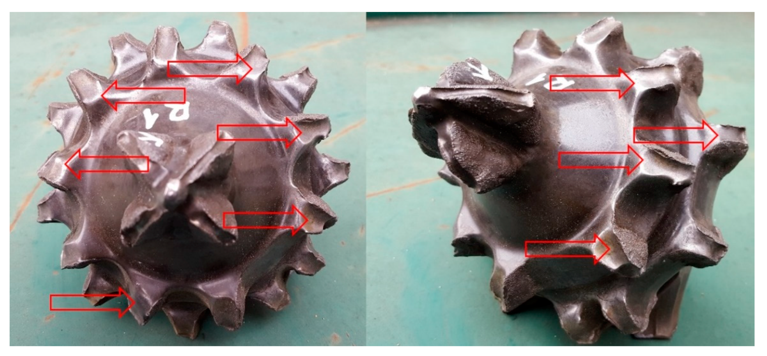
3.3.1. Visual Inspection of the Roller Cone Drill Bit after Drilling

When the drilling rate decreases, the bit was pulled out of the well, cleaned, and visually inspected. The length drilled with the examined bit was 610.70 m.
We have found that the teeth of the bit are uniformly worn. The formation of erosion channels at the tips of the teeth was obvious. According to the initial condition, the teeth of the outer row were worn on the side that was not protected by the erosion protective layer.
The self-sharpening effect was expressed.

3.3.2. Results of Steel Investigations

Steel investigations were carried out for the tooth body steel and carbide coating.
Analysis of the chemical composition of the tooth body, to which the protective carbide coating is applied, was carried out using an optical emission spectrometer. The results of the chemical composition of the steel studied are presented in Table 2.
Based on results from Table 2, we have found that the steel of the base of the teeth of the roller cone drill bit is a so-called cold-work tool steel with increased toughness.

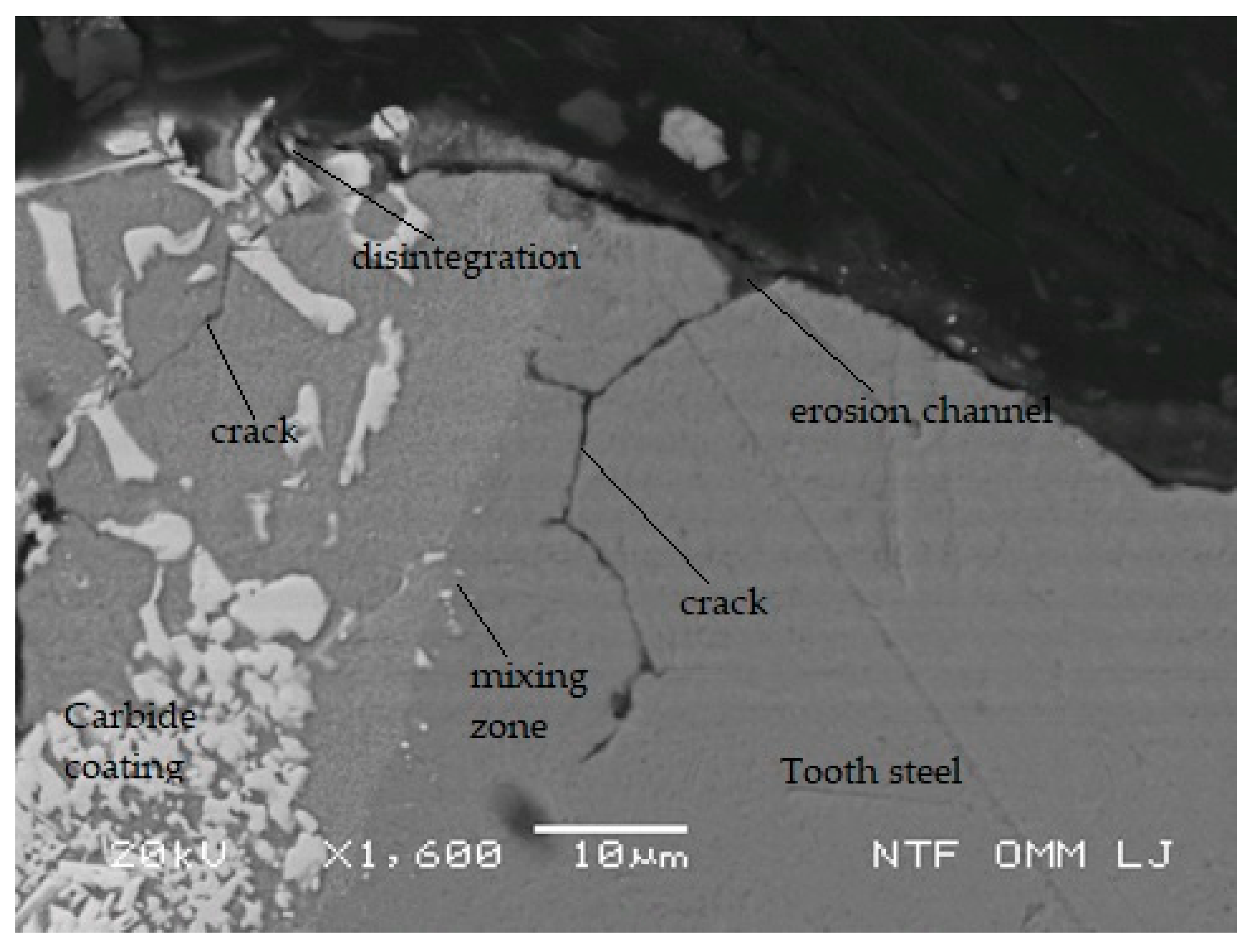
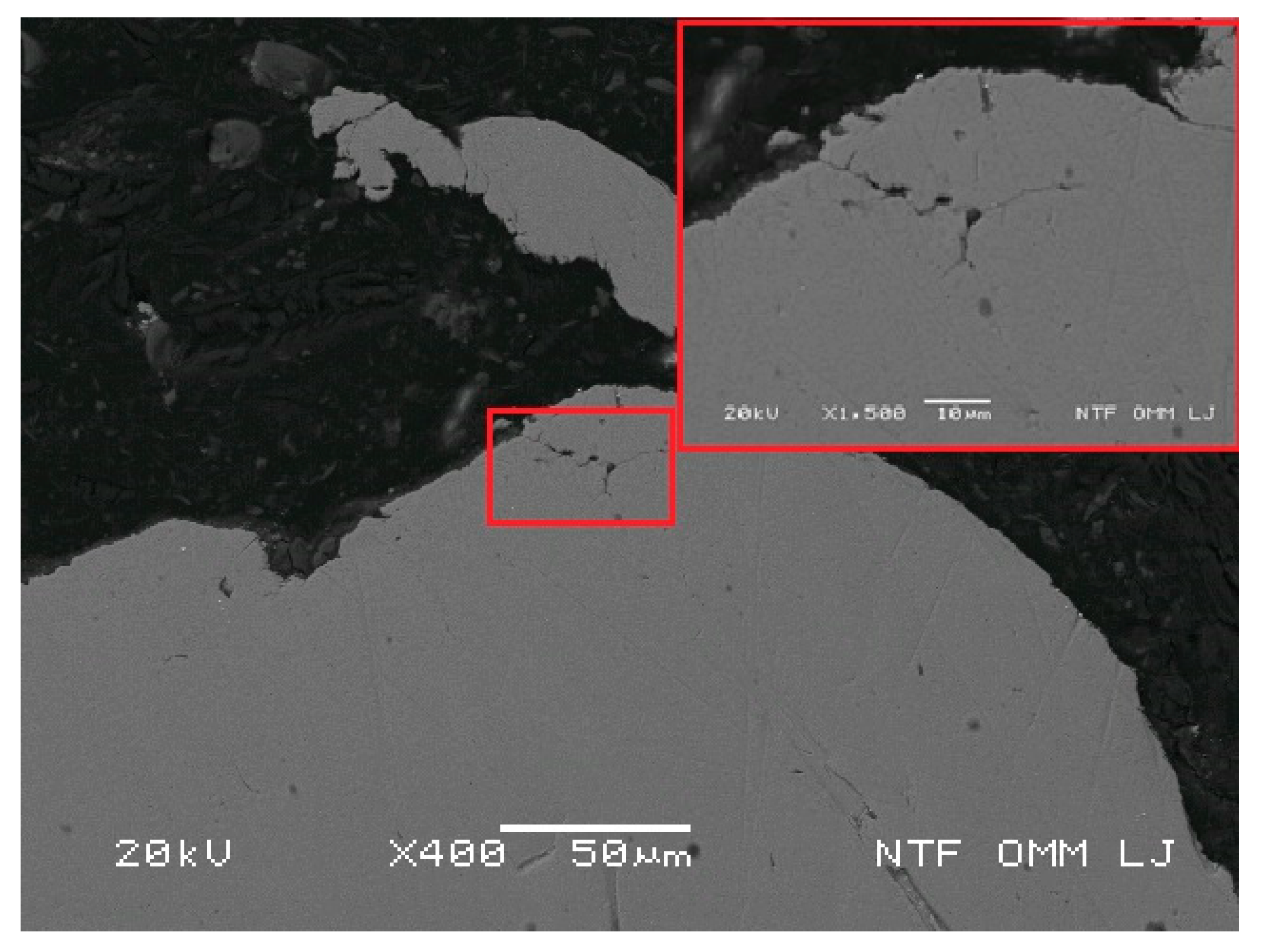
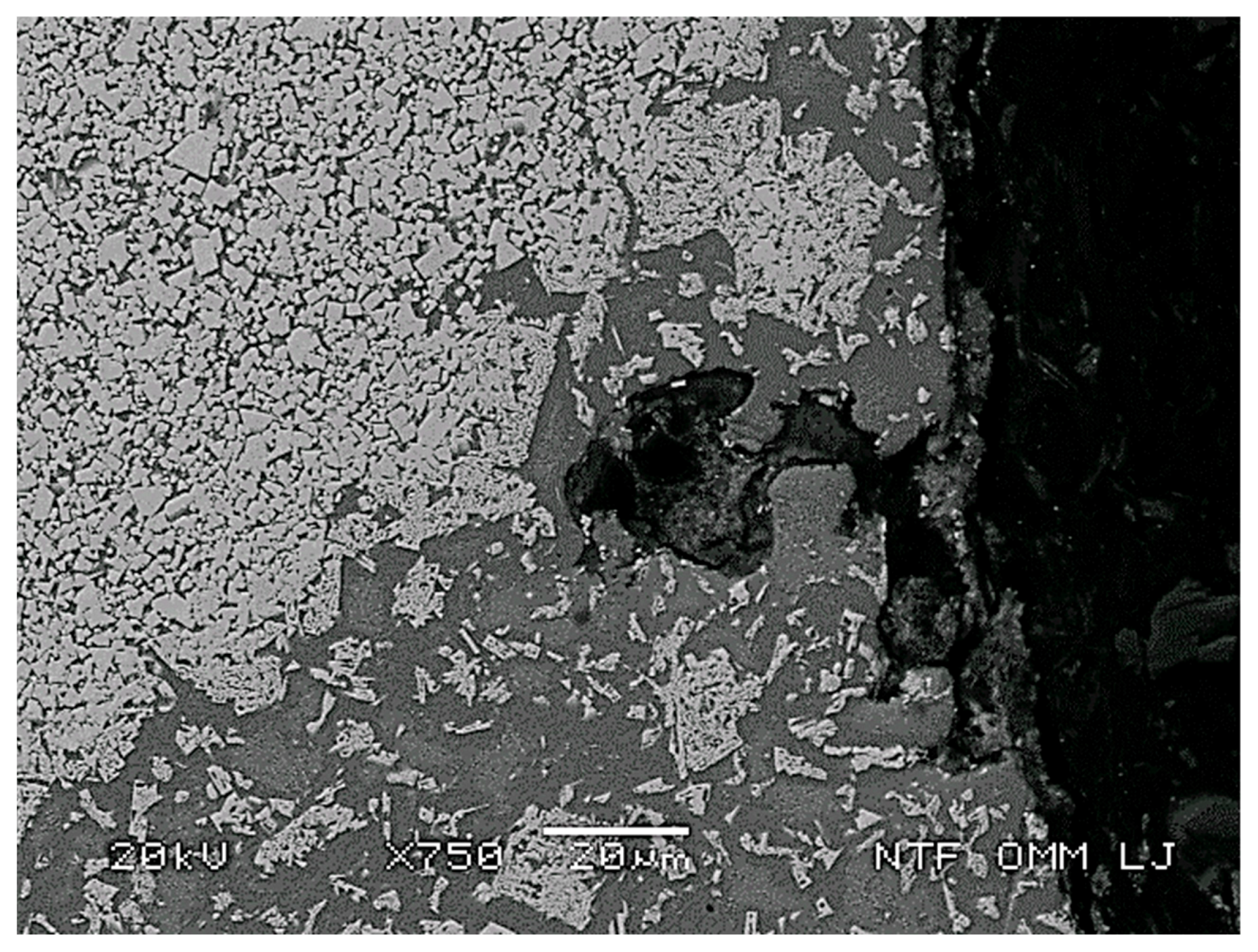
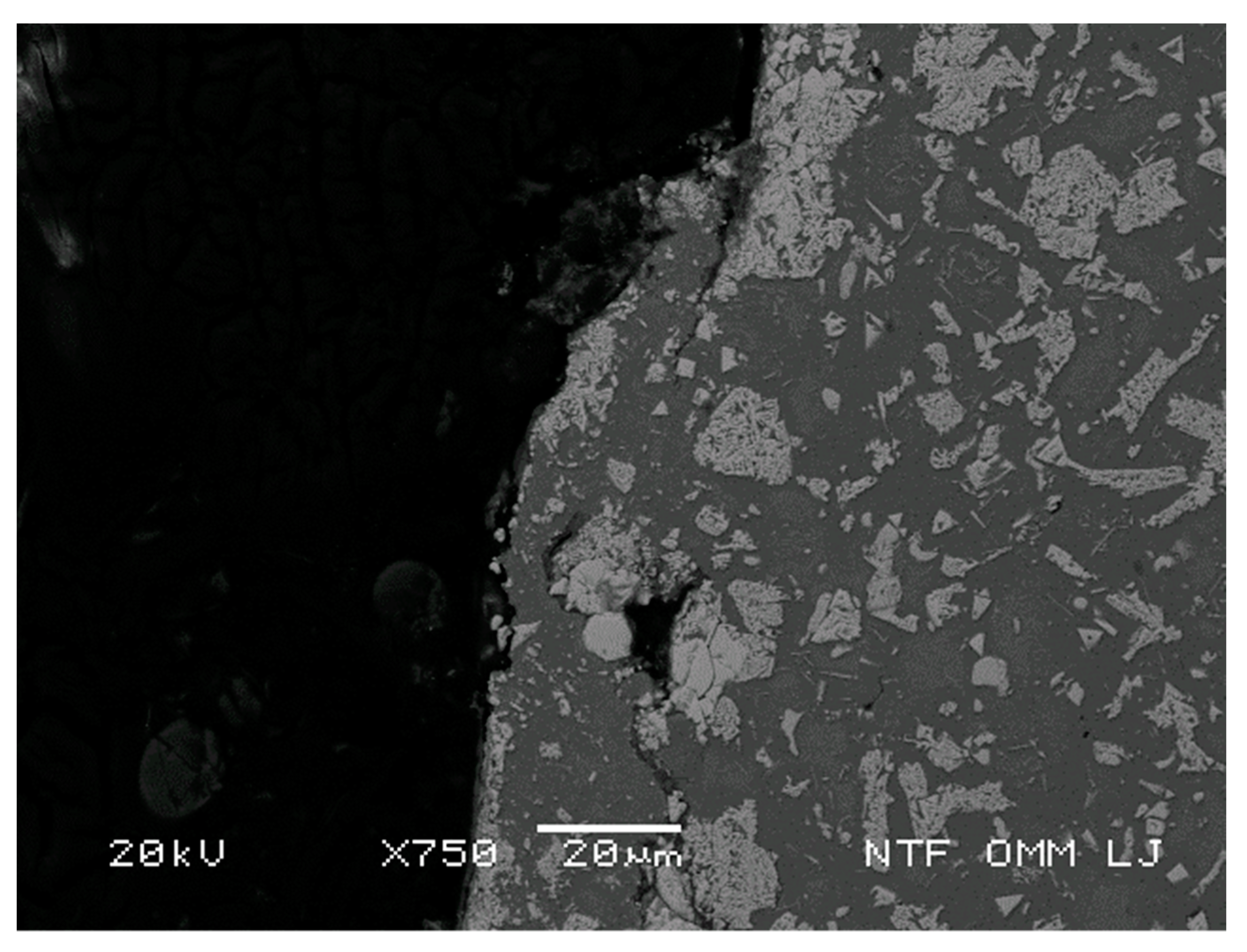
3.3.3. Results of the Investigation of Tooth Steel Materials with SEM

Metallographic examination by SEM analysed the cross-section of the tooth. We examined the base material of the tooth, welded connection with a protective carbide coating and the carbide coating. EDS analyses were also carried out to reveal the chemical compositions of the microstructural constituents. Figure 6 shows a SEM picture of the specimen in the area of separation between the tooth body and the mixed zone due to the effect of welding the carbide coating on the tooth.
Figure 5 and Figure 6 shows that the carbide coating consists of the following microstructures:
  • Prefabricated spherical WC pellets, sizes 100 to 300 µm, bonded with cobalt binder
  • Polycrystalline WC sizes from 10 µm to 100 µm
  • Binder bonding WC spheres and WC polycrystals in Co and Fe-based (matrix) and also containing nanoparticles of WC in sizes from 0.06 µm to 0.25 µm
Site 2 examined from Figure 6 shows that it is a steel with increased levels of Mn, Co and W that have entered the transition zone from a derived carbide coating based on a cobalt alloy in which particles of tungsten carbide are distributed.
The analyses at sites 3 and 5 confirm this. The presence of other elements is due to the larger volume analysed, some of which contains background material.
The results of the metallographic examinations are given in Table 3.
Carbon concentration for each microstructural component is not listed in Table 3 because quantitative values for carbon obtained by analysis of EDS are not quantitatively accurate. However, it is known that tungsten is in the form of tungsten carbide, which is clearly seen in Figure 6 at positions 3, 4 and 5.

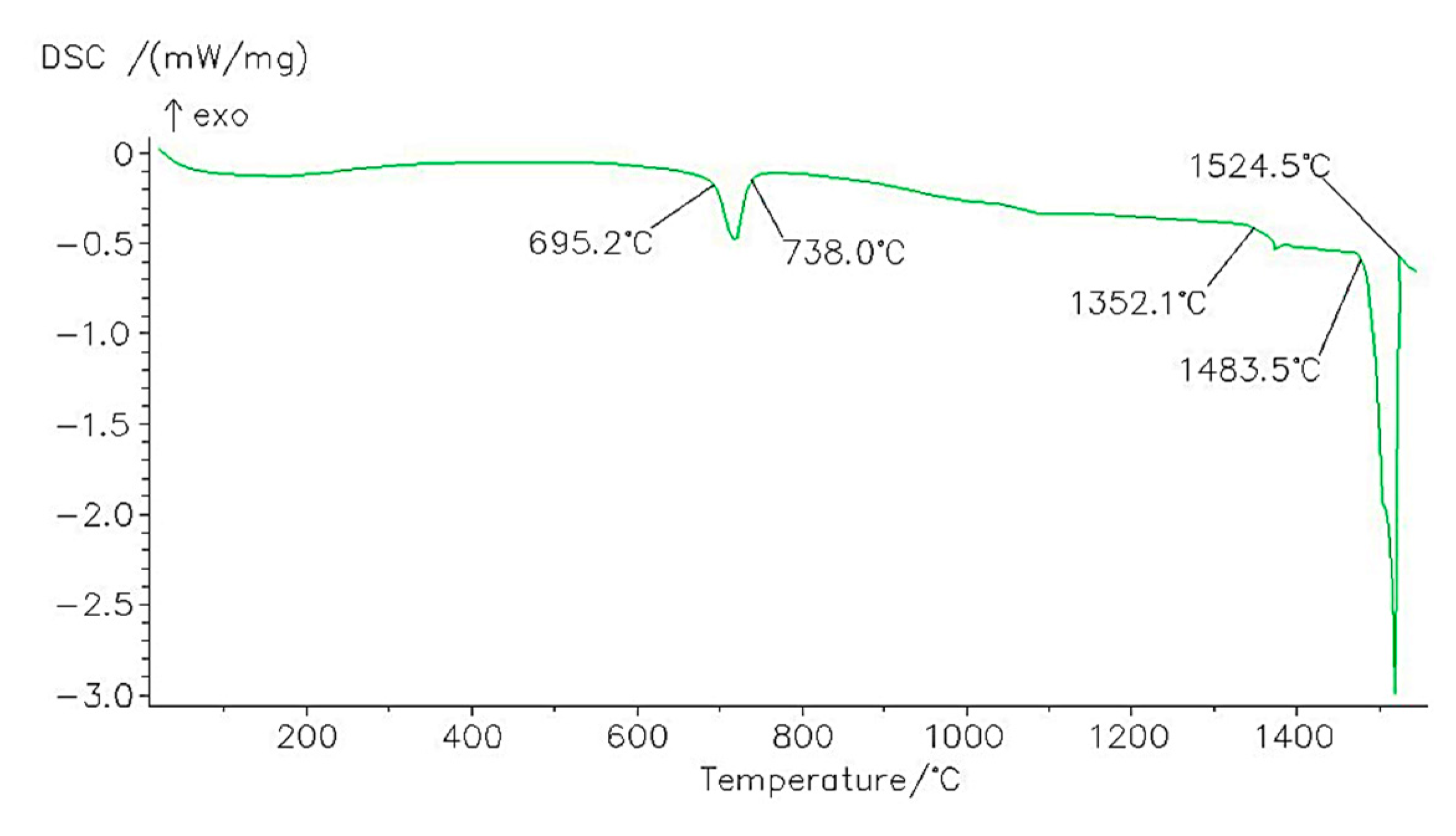
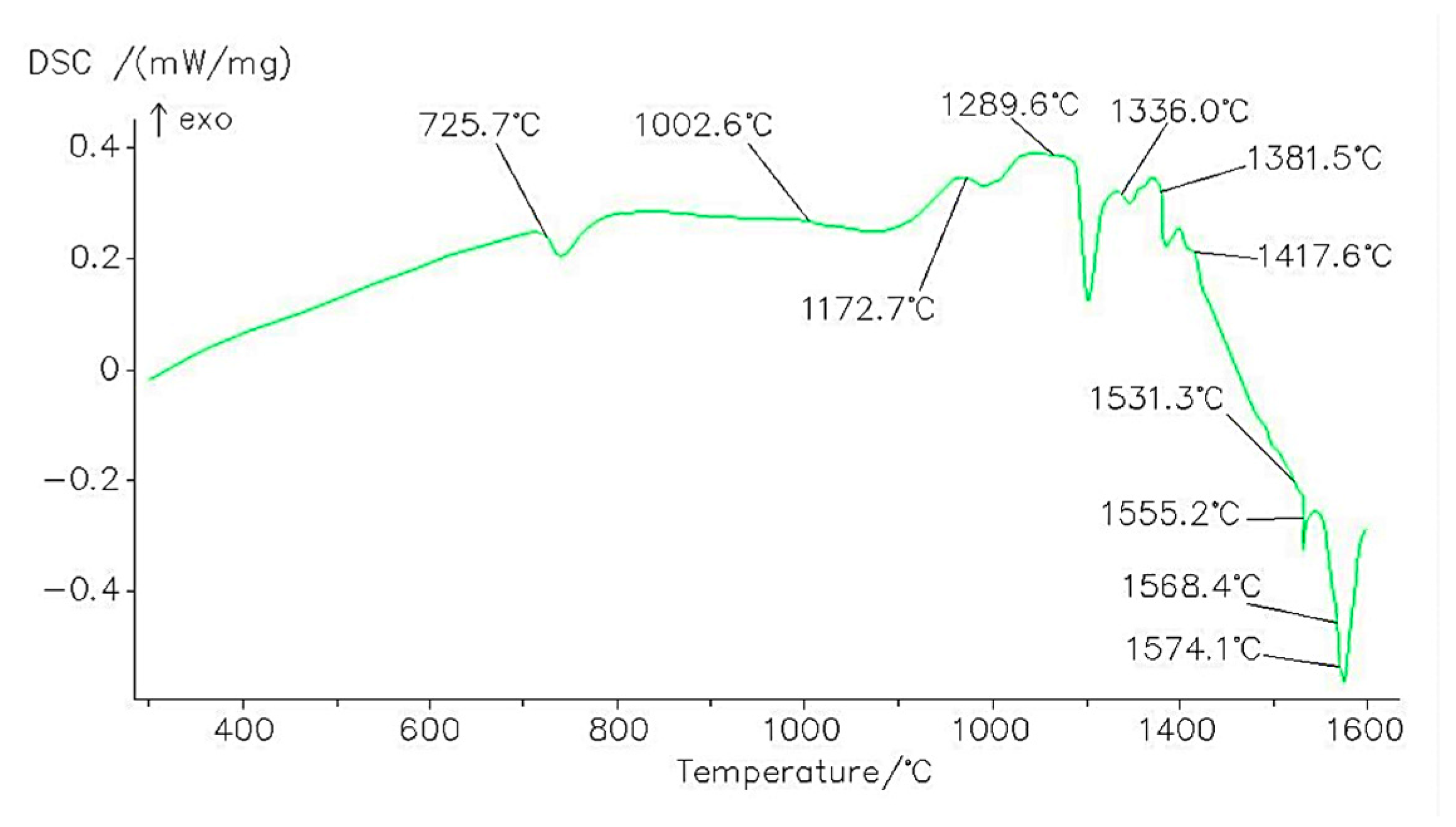
3.3.4. Results of Examination of Tooth Steel and Carbide Coating by STA

The results (Figure 7) of the STA of the steel extracted from the tooth body show that at a temperature of 695.2 °C the beginning of the eutectoid transformation is in the solid state. The transformation was completed at 738 °C. At this temperature the matrix of the steel has the crystal structure of austenite. The low temperature eutectics begins to melt at 1352.1 °C and up to 1483.5 °C. Then the primary crystals of austenite begin to melt, and the melting is completed at 1524.5 °C.
Figure 8 shows the heating curve of the sample of carbide coating examined. The sample contains a thin layer of a transition zone between the steel of the substrate and the carbide coating. The eutectoid transformation begins at the temperature of 725.7 °C. This is undoubtedly related to the part of the transition zone between the substrate steel and the carbide coating, because it is not characteristic for the carbide coating. At 1002.6 °C, the dissolution of the elements from the transition zone in the cobalt base of the carbide coating begins. The carbide coating melting is recorded at 1289.6 °C. It ends at a temperature of more than 1600 °C. The WC particles remained solid at a temperature of 1600 °C after completion of the melting process of the carbide coating binder.

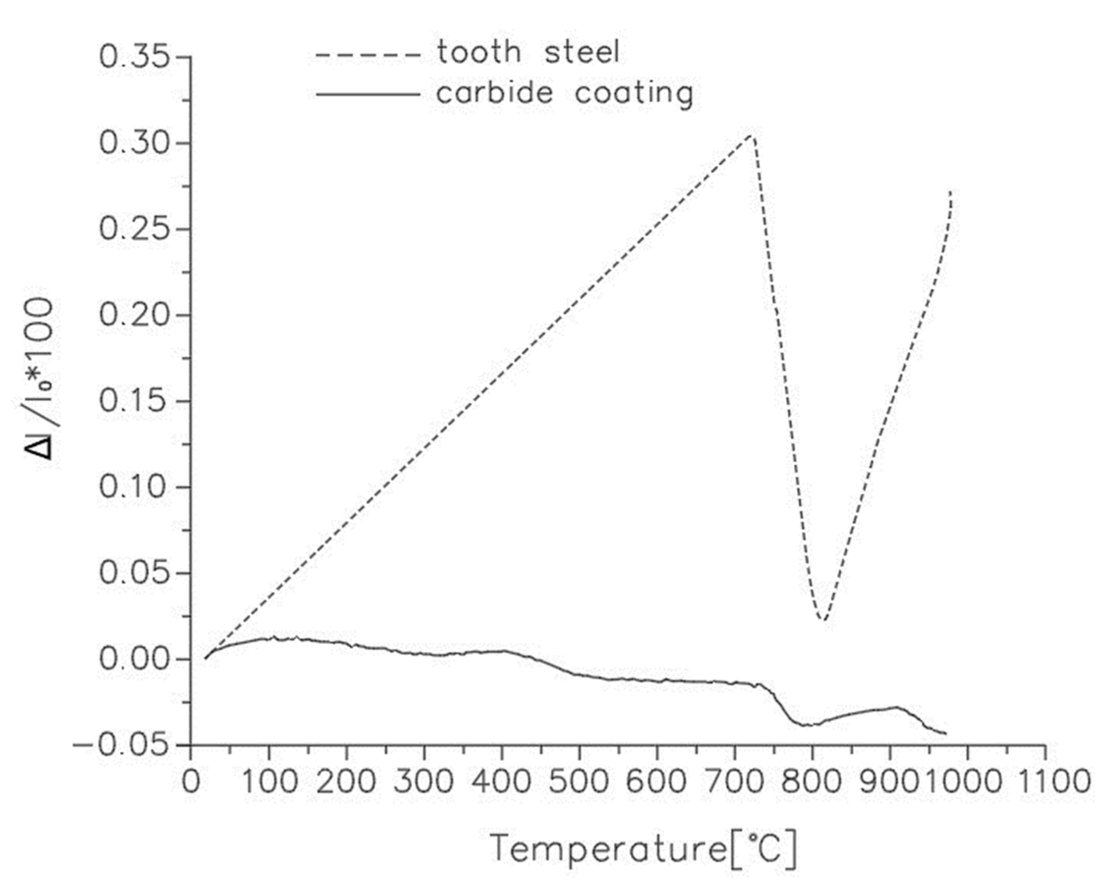
3.3.5. Results of Examination of Materials in a Low–Temperature Dilatometer

The dilatometric heating curves of the carbide coating and the steel from which the teeth of the bit are made are shown in Figure 9. The steel extends linearly on heating to eutectoid change temperatures. The slope of the curve corresponds to the coefficient of thermal expansion of cold-work tool steel. In contrast, the curve of the investigated carbide coating sample shows a flatter curve. It follows that the coefficient of thermal expansion of the carbide coating is significantly lower. In the range of operating temperatures during drilling, the difference is significant and is 0.15% in absolute terms. The difference is important because it leads to a strong increase in internal stresses, especially in the transition zone. Thus, the transition zone represents a favorable location for the initiation and propagation of cracks. The temperature of 725.7 °C is the beginning of the eutectoid transformation of the tooth substrate. It is completed by austenitization of the steel at a temperature of 820 °C. We can observe the deviation of the dilatometric curve of the carbide coating in the region of eutectoid transformation. The deviation may be associated with the eutectoid transformation of the thin layer of the transition zone on the carbide coating, but the reference temperatures are little higher.

3.3.6. Results of the Microhardness Test According to Vickers

Vickers microhardness tests were also performed. The measurements showed that the tooth steel has an average hardness of 328 HV, while the hardness of the carbide coating is expected to be much higher at up to 2200 HV (average 1667 HV).

4. Discussion

Figure 10 shows the wear of the cutting elements due to the erosional action of the rock material, which contains a high proportion of silicate particles (Table 1). The reduction and change in the dimensions of the teeth and the formation of erosion channels at the tips of the teeth are evident.
The formation of erosion channels at the tips of the teeth can be attributed to the decay of the carbide coating during drilling. The disintegration of the coating allowed the siliceous particles in the drilling fluid to act erosively on the newly exposed tooth surfaces. Due to the significant difference in thermal expansion properties and strength between the carbide and the tooth substrate material, cracks were initiated and continued during the drilling process, as shown in Figure 11. The latter resulted in the disintegration of the carbide coating. The deviation of the carbide coating resulted in the opening of a new surface of the tooth steel through which the drilling fluid, containing a large quantity of silicate abrasive constituents, flowed. This is the cause of the consequent loss of tooth steel material. The process of erosion of the tooth steel and degradation of the carbide coating was repeated cyclically. Due to these influences, the geometry of the teeth changed. Steel material that was not protected with a carbide coating wore out faster than parts of the teeth that were protected with a carbide coating. The erosion-resistant carbide coating on the tip and edge of the teeth is brittle and gradually disintegrates under the influence of the load applied to the bit and the associated pressure and shear forces in contact with the rock, causing the material to heat up and cool down during drilling. In our case, we could not estimate with certainty the temperature at the tip of the tooth during drilling. However, it can be assumed that the temperature was lower than the temperature that affects the microstructural changes in the steel material. From the results of the microhardness measurements of the tooth steel, it appears that it has a constant value from the surface to the centre of the tooth. It follows that no microstructural changes in the steel have occurred during drilling. In the general case of tempering steel with martensitic matrix, the hardness value decreases to a certain extent, and in the case of hardening, the hardness value increases. No such changes in material hardness were found. Investigation in a low temperature dilatometer revealed the thermal differences between the properties of the carbide coating and the tooth substrate material. The difference is evident at a temperature above 100°C. These temperatures occur when the tip of the tooth tip is in contact with the rock. During the time when the tooth rotates around the roller axis, its temperature decreases due to the influence of the drilling fluid. In cases where the duration of the heating and cooling process of the tooth is short enough, there is no immediate detachment of the carbide coating from the tooth steel. However, micro-cracks form at the point of contact between the carbide coating and the tooth steel, i.e. in the mixing zone. These micro-cracks eventually propagate along the junction between the materials and lead to a deviation of the carbide material. This phenomenon was observed only at the tip of the teeth. We did not observe this phenomenon on the sides of the teeth.
The effects of erosion due to the high content of silicate particles in the drilling fluid can be observed both on the tooth body, which is not protected with carbide coating, and on the carbide coating itself.
Figure 12 shows the formation of microcracks and erosion channels on the tooth edges that are not protected by carbide coating.
Erosion channels can also be observed in the carbide coating itself. When the drilling fluid, which contains a large amount of siliceous microparticles, penetrates into the microchannels, they widen the channels by erosion. The microchannels form mainly in the matrix of the carbide coating surrounding the tungsten carbide grains (Figure 13 and Figure 14).
Based on the above factors, it is obvious that the areas of the teeth that are not protected with a carbide coating wear much faster than the erosion-protected areas. The uneven wear of the teeth causes the dimensions of the teeth to change, resulting in a self-sharpening effect. If the teeth were not protected by a carbide coating, the rock particles in the drilling fluid and the abrasiveness of the rock would wear away the entire teeth of the roller cone drill bit, causing the tooth geometry to wear completely and much faster. This means a shorter efficiency time of the roller cone bit.

5. Conclusions

The article describes a complex analysis of several factors to determine the characterization of the wear of roller cone bit. The investigated roller cone bit was used to drill an interval of 610.70 m into the sandstone, which contains more than 47% silicates, which, mixed with the drilling fluid, have an abrasive effect on the steel components of the roller cone bit. The wear of the bit teeth manifested itself in the formation of erosion channels on the steel surfaces. The interaction between the rock and the bit teeth is closely related to the load on the bit and the washout of the drilled rock material from the area of the bit. The bit teeth heat up when they come into contact with the rock and then cool down due to the influence of the cold drilling fluid. During this phase, complex stresses occur on both the tooth steel and the carbide coating, which can exceed the elastic range and reach the plastic range, resulting in local fracture of the carbide coating. The impacts of drilling, heating, and cooling the teeth disintegrated the carbide coating that protects the teeth from excessive wear. The disintegration of the protective carbide coating resulted in new surfaces of unprotected steel that were exposed to the aggressive erosive action of the rock particles in the drilling fluid. Aggressive rock particles with a diameter of a few µm to 3 mm acted erosively on the steel of the teeth in the fast-flowing drilling fluid, which is the cause of erosive micro-damage. The process of steel erosion led to the loss of steel in the tooth area and the development of new wear in the tooth tip area, resulting in localised breakdowns of the erosion-resistant carbide coating. The carbide coating then disintegrated again under the influence of the loads applied during drilling. Thus, the process repeats cyclically, leading to a change in the geometry of the teeth of the roller cone drill bit and the expression of the self-sharpening effect.
The development of erosion protection of roller cone drill bits is taking place in two directions, firstly by the use of new materials from which the teeth of the roller cone drill bit are made, and secondly by the development of new methods for the effective bonding of erosion protection layers on the tooth steel.
Development in terms of improving the materials of the teeth made along with the roller can be in the direction of developing gradient materials. The ideal roller cone drill bit should have a tough tooth core and a very hard and abrasion resistant surface. The bond between these two materials must be continuous and coherent. This type of tooth design could be achieved by different layering techniques of different materials from the same family (e.g., different composition of the carbide coating), which would vary in toughness and abrasion resistance depending on the distance from the tooth centre, or by using a bionic coupling of a highly erosion-resistant coating.
Recently, in the Materials and Metallurgy Department, we have begun research that should lead to the development of new wear-resistant alloys suitable for the cutting mechanisms of roller cone drill bits and TBMs. We will present the results of our research in the future.

Author Contributions

Conceptualization, J.Š., Ž.V. and P.M.; methodology, J.Š. and P.M.; software, P.M. and B.J.; validation, J.Š. and P.M.; formal analysis, J.Š. and P.M.; investigation, J.Š. and P.M.; resources, J.Š. and B.J.; data curation, P.M.; writing—original draft preparation, J.Š.; writing—review and editing, P.M., B.J. and Ž.V.; visualization, J.Š.; supervision, P.M. and Ž.V. All authors have read and agreed to the published version of the manuscript.

Funding

This research received no external funding.

Institutional Review Board Statement

Not applicable.

Informed Consent Statement

Not applicable.

Data Availability Statement

No data supporting results.

Conflicts of Interest

The authors declare no conflict of interest.

References

  1. Peter, W. Wear-Resistant NanoComposite Stainless Steel Coatings and Bits for Geothermal Drilling. In Proceedings of the Geothermal Technology Program, The Antares Group, Crystal City Hyatt, Alexandria, VA, USA, 18–20 May 2010. [Google Scholar]
  2. Eremin, E.N.; Yurov, V.M.; Guchenko, S.A.; Laurynas, V.C.; Kasymov, S.S. Antifriction Superhard Coatings for Drill Bits and Boring Cutters. Procedia Eng. 2016, 152, 608–612. [Google Scholar] [CrossRef] [Green Version]
  3. Popescu, C.; Cristea, D.; Bita, B.; Cristescu, R.; Craciun, D.; Chioibasu, G.D.; Luculescu, C.; Paun, I.; Duta, L.; Popescu, A.C. An Experimental Study on Nano-Carbon Films as an Anti-Wear Protection for Drilling Tools. Coatings 2017, 7, 228. [Google Scholar] [CrossRef] [Green Version]
  4. Jaime, M.C.; Zhou, Y.; Lin, J.S.; Gamwo, I.K. Finite element modeling of rock cutting and its fragmentation process. Int. J. Rock Mech. Min. Sci. 2015, 80, 137–146. [Google Scholar] [CrossRef] [Green Version]
  5. Yang, C.; Jiang, J.; Cao, P.; Wang, J.; Fan, X.; Shang, Y.; Talalay, P. Assessing the efficiency of carbide drill bits and factors influencing their application to debris-rich subglacial ice. Polar Sci. 2017, 13, 50–55. [Google Scholar] [CrossRef] [Green Version]
  6. Hu, Q.; Zhu, H.; Ren, H. Research on shape parameters of circular arc disc teeth for three-cone bit. Petroleum 2018, 4, 108–114. [Google Scholar] [CrossRef]
  7. Geoffroy, H.; Nguyen Minh, D. Study on interaction between rocks and worn PDS’S cutter. Int. J. Rock Mech. Min. Sci. 1997, 34, 95. [Google Scholar] [CrossRef]
  8. Zhou, Y. Numerical Modeling of Rock Drilling with Finite Elements. Ph.D. Thesis, University of Pittsburgh, Pittsburgh, PA, USA, 2013. [Google Scholar]
  9. Dagrain, F.; Lamine, E.; Delwiche, R.; Golard, N. Characterization of the performances of small diameter drill bits for the optimization of the drilling parameters. In Proceedings of the 2nd International Conference on Stone and Concrete Machining (ICSCM), Dortmund, Germany, 14–15 November 2013. [Google Scholar]
  10. Kanyanta, V.; Dormer, A.; Murphy, N.; Ivankovic, A. Impact fatigue fracture of polycrystalline diamond compact (PDC) cutters and the effect of microstructure. Int. J. Refract. Met. Hard Mater. 2014, 46, 145–151. [Google Scholar] [CrossRef] [Green Version]
  11. Günen, A. Micro-Abrasion Wear Behavior of Thermal-Spray-Coated Steel Tooth Drill Bits. Acta Phys. Pol. A 2016, 130, 217–222. [Google Scholar] [CrossRef]
  12. Karasawa, H.; Ohno, T.; Miyazaki, K.; Eko, A. Experimental results on the effect of Bit wear on torque response. Int. J. Rock Mech. Min. Sci. 2016, 84, 1–9. [Google Scholar] [CrossRef]
  13. Yahiaoui, M.; Paris, J.Y.; Delbé, K.; Denape, J.; Gerbaud, L.; Dourfaye, A. Independent analyses of cutting and friction forces applied on a single polycrystalline diamond compact cutter. Int. J. Rock Mech. Min. Sci. 2016, 85, 20–26. [Google Scholar] [CrossRef]
  14. Al-Sudani, J.A. Real-time monitoring of mechanical specific energy and bit wear using control engineering systems. J. Pet. Sci. Eng. 2017, 149, 171–182. [Google Scholar] [CrossRef]
  15. Botti, L.; Mora, C.; Antonucci, A.; Carty, P.; Barr, A.; Rempel, D. Carbide-tipped bit wear patterns and productivity with concrete drilling. Wear 2017, 386–387, 58–62. [Google Scholar] [CrossRef]
  16. Jones, H.G.; Norgren, S.M.; Kritikos, M.; Mingard, K.P.; Gee, M.G. Examination of wear damage to rock-mining hardmetal drill bits. Int. J. Refract. Met. Hard Mater. 2017, 66, 1–10. [Google Scholar] [CrossRef]
  17. Olsson, M.; Yvell, K.; Heinrichs, J.; Bengtsson, M.; Jacobson, S. Surface degradation mechanisms of cemented carbide drill buttons in iron ore rock drilling. Wear 2017, 388–389, 81–92. [Google Scholar] [CrossRef]
  18. Timonin, V.V.; Smolentsev, A.S.; Shakhtorin, O.; Polushin, N.I.; Laptev, A.I.; Kushkhabiev, A.S. Causes of wear of PDC bits and ways of improving their wear resistance. In Proceedings of the All-Russian Conference on Challenges for Development in Mining Science and Mining Industry Devoted to the 85th Anniversary of Academician Mikhail Kurlenya, Novosibirsk, Russia, 3–6 October 2016. [Google Scholar]
  19. De Lacalle, L.N.L.; Fernández-Larrinoa, J.; Rodríguez-Ezquerro, A.; Fernández-Valdivielso, A.; López-Blanco, R.; Azkona-Villaverde, I. On the cutting of wood for joinery applications. Proc. Inst. Mech. Eng. Part B J. Eng. Manuf. 2015, 229, 940–952. [Google Scholar] [CrossRef]
  20. Neville, A.; Hodgkiess, T. Characterisation of high-grade alloy behaviour in severe erosion-corrosion conditions. Wear 1999, 233–235, 596–607. [Google Scholar] [CrossRef]
  21. Zhao, J.; Zhang, G.; Xu, Y.; Wang, R.; Zhou, W.; Yang, D. Experimental and theoretical evaluation of solid particle erosion in an internal flow passage within a drilling bit. J. Pet. Sci. Eng. 2018, 160, 582–596. [Google Scholar] [CrossRef]
  22. Neville, A.; Reyes, M.; Hodgkiess, T.; Gledhill, A. Mechanisms of wear on a Co-base alloy in liquid-solid slurries. Wear 2000, 238, 138–150. [Google Scholar] [CrossRef]
  23. Northrop, I.T. The joining of tungsten carbide hardmetal to steel. J. South. Afr. Inst. Min. Metall. 1987, 87, 125–135. [Google Scholar]
  24. Chuanliu, W. Experimental Study on Matrix Wear Resistance of Bionic Coupling Bits. Procedia Eng. 2014, 73, 98–102. [Google Scholar] [CrossRef] [Green Version]
  25. Katinas, E.; Antonov, M.; Jankauskas, V.; Tarraste, M. The Effect of Spark Plasma Sintering Thermal Cycle on Behaviour of Fe-Based Hardfacins Reinforced with WC and WC-Based Hardmetal. Key Eng. Mater. 2019, 799, 3–8. [Google Scholar] [CrossRef]
  26. Claver, A.; Jiménez-Piqué, E.; Palacio, J.F.; Almandoz, E.; de Ara, J.F.; Fernández, I.; Santiago, J.A.; Barba, E.; García, J.A. Comparative Study of Tribomechanical Properties of HiPIMS with Positive Pulses DLC Coatings on Different Tools Steels. Coatings 2021, 11, 28. [Google Scholar] [CrossRef]
  27. Naganawa, S. Feasibility study on roller-cone bit wear due bit detection from axial bit vibration. J. Pet. Sci. Eng. 2012, 82–83, 140–150. [Google Scholar] [CrossRef]
  28. Rashidi, B.; Hareland, G.; Wu, Z. Performance, simulation and field application modeling of rollercone bits. J. Pet. Sci. Eng. 2015, 113, 507–517. [Google Scholar] [CrossRef]
Figure 1. Settings of rollers for soft rock formations roller cone drill bits.
Coatings 11 01308 g001
Figure 2. The action of the bit tooth on the rock.
Coatings 11 01308 g002
Figure 3. Simplified sketch of the movement of the drilling fluid in the area of the rollers.
Coatings 11 01308 g003
Figure 4. Worn roller cone drill bit (Ø215.9 mm) after drilled interval.
Coatings 11 01308 g004
Figure 5. Cross section of a worn tooth with a protective carbide coating.
Coatings 11 01308 g005
Figure 6. Tooth SEM image: 1—substrate (tooth base steel), 2—matrix of WC coating in transition zone, 3—WC, 4—WC in transition zone, 5—WC in transition zone, Zones: A—coating, B—transition zone (mixing zone), C—substrate (tooth body).
Coatings 11 01308 g006
Figure 7. Heating curve of the tooth body steel.
Coatings 11 01308 g007
Figure 8. Heating curve of the carbide coating.
Coatings 11 01308 g008
Figure 9. Dilatometric curves of the substrate steel and the coating.
Coatings 11 01308 g009
Figure 10. Characteristic wear of the teeth of the roller cone bit.
Coatings 11 01308 g010
Figure 11. Formation of microcracks due to different elastic properties of materials.
Coatings 11 01308 g011
Figure 12. Micro cracks and erosion channels.
Coatings 11 01308 g012
Figure 13. Formation of micro erosion channels in carbide coating matrix.
Coatings 11 01308 g013
Figure 14. Formation of micro erosion channels in carbide coating matrix.
Coatings 11 01308 g014
Table 1. Results of the rock investigations (significant variables influencing the wear of the bit materials).
ParameterValueUnits
Uniaxial compressive strength (σ)30MPa
Density (ρ)2.007Mg/m3
Cohesion (c)0.361MPa
Elastic module (E)3098MPa
Angle of internal friction51.2°
Content of SiO247.49%
Content of Al2O310.57%
Content of CaO9.82%
Quartz content47.30%
Dolomite content23.80%
Plagioclases content12.10%
Muscovite/illite content8.30%
Table 2. Chemical composition of the tooth body steel.
ElementMass. %
Ni3.500
Mn0.590
Si0.250
Mo0.201
Cu0.180
C0.145
Cr0.110
Al0.053
V0.010
P0.007
Nb0.005
Ti0.005
N<0.003
S0.002
Fe96.5
Table 3. Elemental composition of the material at the various locations of the tooth according to Figure 6.
ElementLocation
12345
Error 2-sigConcentrationError 2-sigConcentrationError 2-sigConcentrationError 2-sigConcentrationError 2-sigConcentration
at.%wt.%at.%wt.%at.%wt.%at.%wt.%at.%wt.%
Si0.4030.4970.250------------
Mn0.4310.3470.3421.0312.4452.244------0.7782.5031.284
Fe6.21895.87695.9585.77290.15884.1280.5942.9130.903---3.46255.16628.772
Ni0.9443.2793.4500.4940.9580.940---------
Co---1.0553.3973.345------0.6782.3451.291
W---1.5663.0149.3432.62797.08799.0975.563100.00100.002.19639.98668.653
Publisher’s Note: MDPI stays neutral with regard to jurisdictional claims in published maps and institutional affiliations.

