
Characterization and Parametric Optimization of Performance Parameters of DLC-Coated Tungsten Carbide (WC) Tool Using TOPSIS


Abstract
:1. Introduction
2. Materials and Methods
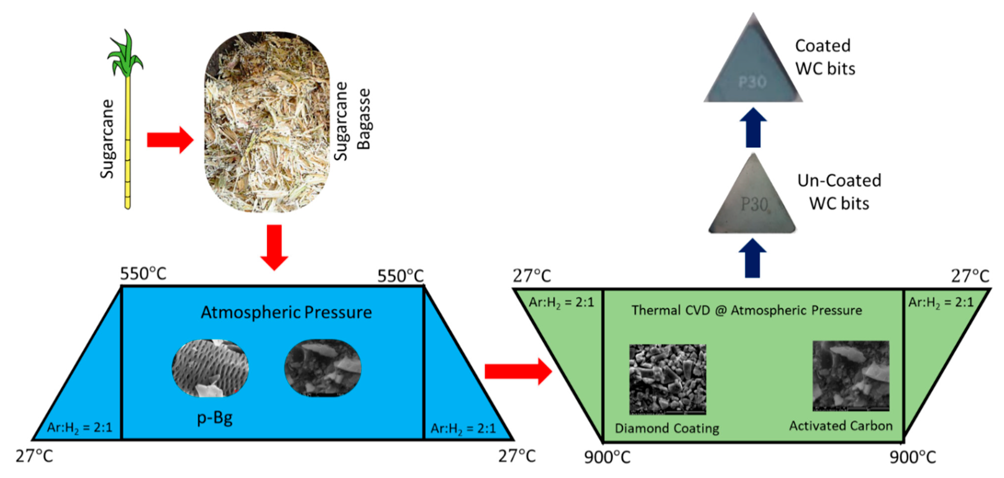
2.1. Coating Method
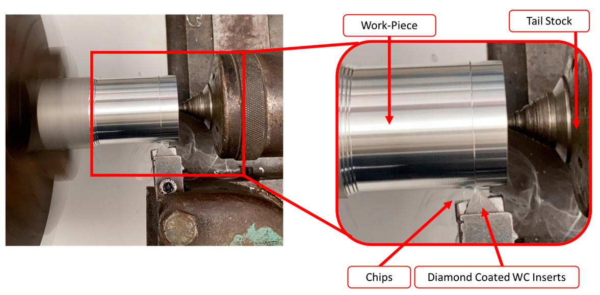
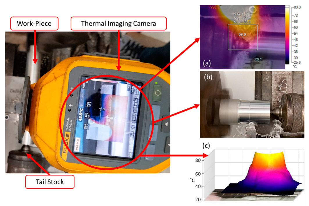
2.2. Turning Process
3. Characterization
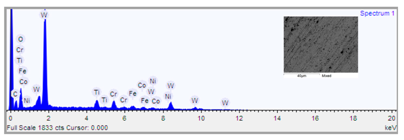
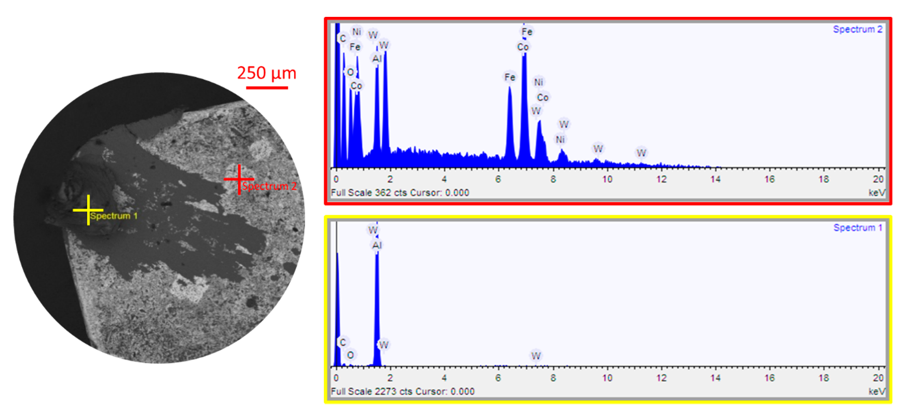
3.1. EDaX and XRD Analysis
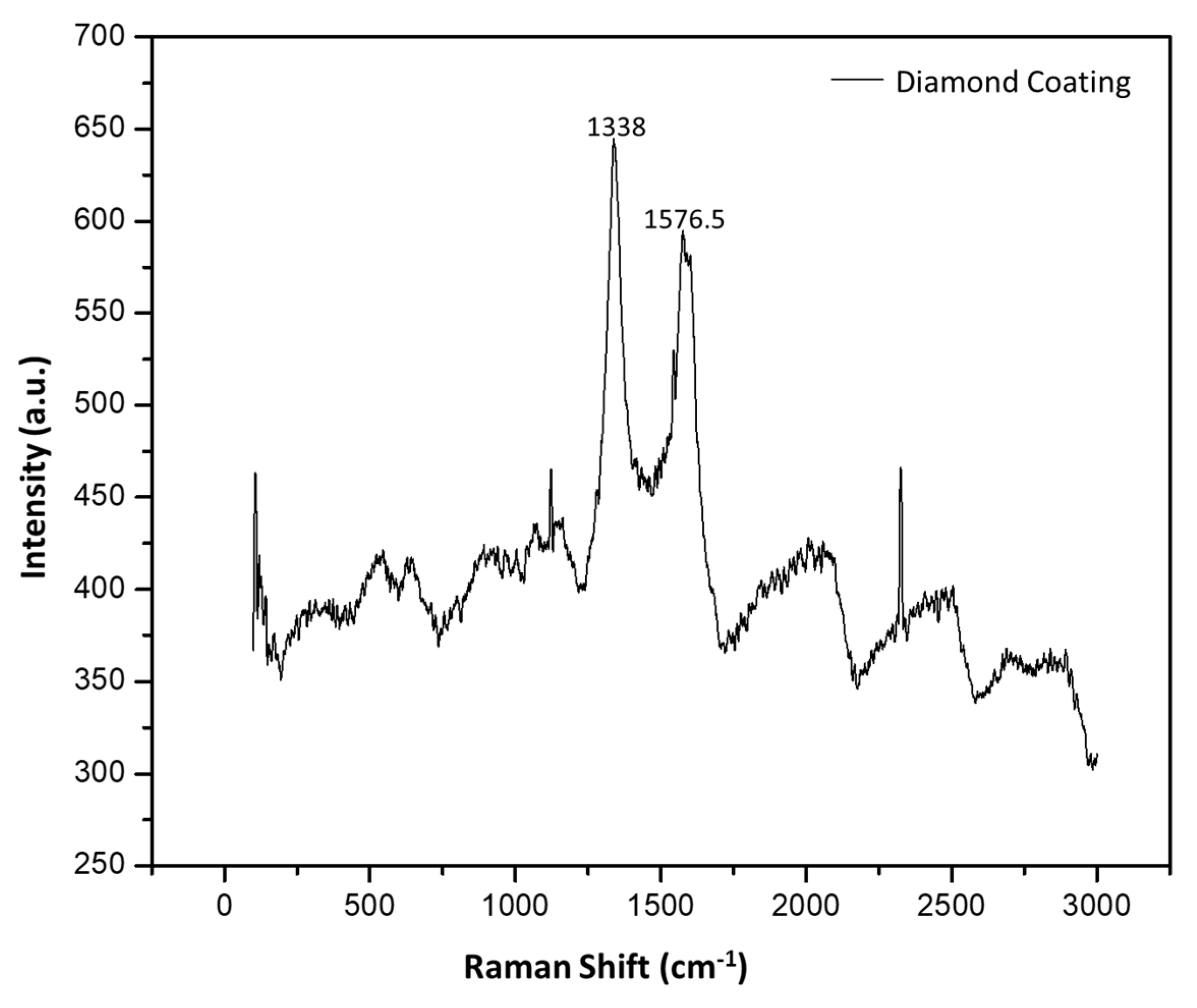
3.2. Raman Spectrum
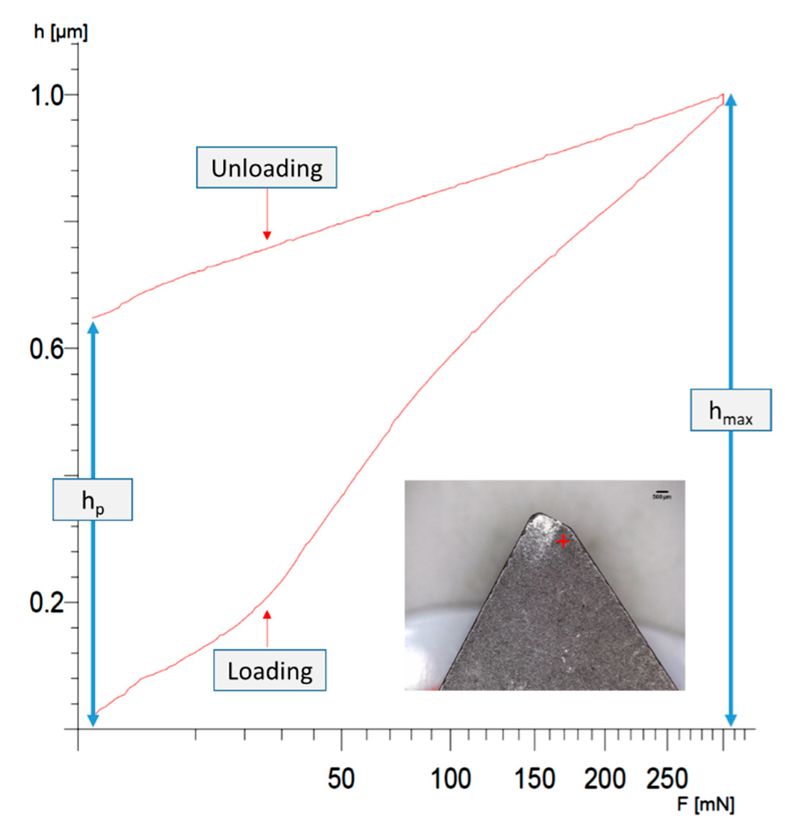
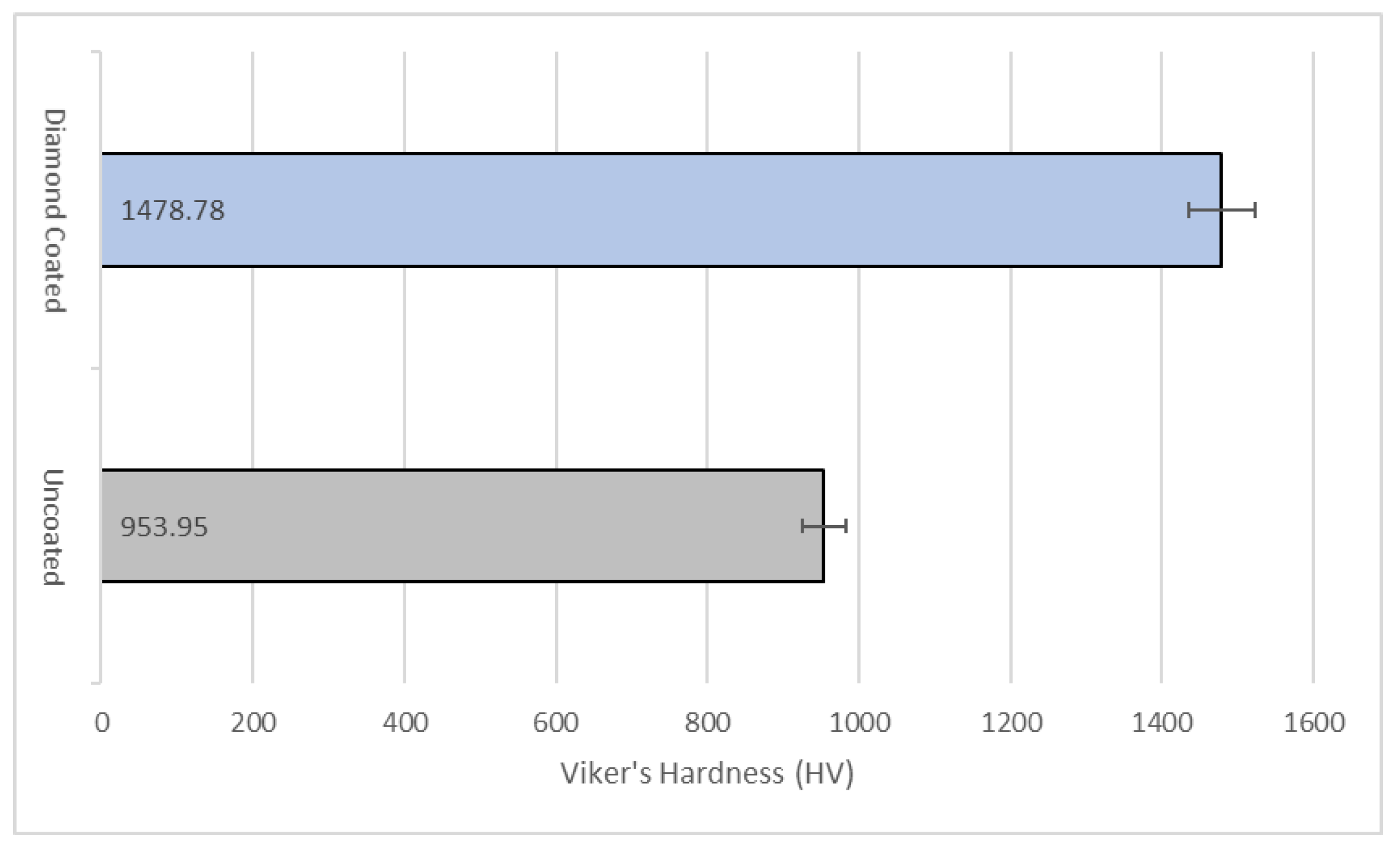
3.3. Hardness
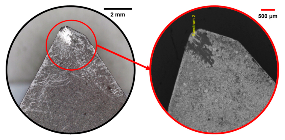
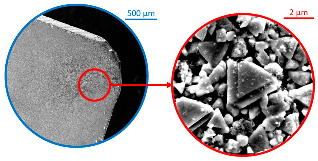
3.4. FESEM
4. Results and Discussion
4.1. Selecting the Orthogonal Array (OA)
4.2. TOPSIS Based on Entropy Weight Method
4.2.1. Formation of Decision Matrix
4.2.2. Standardizing the Decision Matrix
4.2.3. Using the Entropy Method for the Determining the Weight for Response Variable
4.2.4. Determination of Weight
4.2.5. Calculation for Finding the Negative and Positive Ideal Solution
4.2.6. Determination of the Relative Distance
4.2.7. Formation of Sequence Table While Evaluating the TOPSIS Value
4.3. Discussion
5. Conclusions
- (a)
- X-ray diffraction spectra for the coated tungsten carbide substrate confirmed the presence of DLC coating developed on tungsten carbide (WC) substrate.
- (b)
- The peak at 1338 cm−1 in the Raman spectra also supported the presence of DLC coating on tungsten carbide (WC) inserts. The result of the presence of DLC is in correlation with the SEM images.
- (c)
- It was also observed that the hardness of the WC was increased by a factor of 1.5 after the coating process. The average Vickers hardness was 953.95 HV for the un-coated tungsten carbide (WC) and for the DLC-coated WC, the hardness increased to 1478.78 HV.
- (d)
- The optimum value of depth of cut for achieving the minimum value of the selected response variables using the self-developed DLC-coated tungsten carbide (WC) tool inserts in a turning process, was found to be 0.635 mm.
- (e)
- The optimum values of cutting speed and feed for achieving the minimum value of the selected response variables using the self-developed DLC-coated tungsten carbide (WC) tool inserts in a turning process, were found to be 480 m/min and 0.25 mm/rev respectively.
Author Contributions
Funding
Institutional Review Board Statement
Informed Consent Statement
Data Availability Statement
Acknowledgments
Conflicts of Interest
Nomenclature
| WC | Tungsten Carbide |
| CVD | Chemical Vapor Deposition |
| DLC | Diamond-like Carbon |
| DOC | Depth of Cut |
| Tc | Temperature in the Cutting Zone |
| p-SBg | Pyrolyzed Sugarcane Bagasse |
| FESEM | Field Emission Scanning Electron Microscope |
| f | Feed |
| Ra | Surface Roughness |
| Vc | Cutting Speed |
| XRD | X-ray Diffraction |
| SBg | Sugarcane Bagasse |
References
- Tanaka, T.; Akasawa, T. Machinability of Hypereutectic Silicon-Aluminum Alloys. J. Mater. Eng. Perform. 1999, 8, 463–468. [Google Scholar] [CrossRef]
- Boyer, R.; Cotton, J.; Mohaghegh, M.; Schafrik, R. Materials considerations for aerospace applications. MRS Bull. 2015, 40, 1055–1066. [Google Scholar] [CrossRef] [Green Version]
- Ed, F.; Chris, E. Basics of CVD Diamond-Coated Cutting Tools. American Mold Builder. 2017. Available online: https://americanmoldbuilder.com/articles/2017/basics-of-cvd-diamond-coated-cutting-tools/ (accessed on 12 February 2021).
- Kumar, C.S.; Majumder, H.; Khan, A.; Patel, S.K. Applicability of DLC and WC/C low friction coatings on Al2O3/TiCN mixed ceramic cutting tools for dry machining of hardened 52100 steel. Ceram. Int. 2020, 46, 11889–11897. [Google Scholar] [CrossRef]
- Aschauer, E.; Riedl, H.; Koller, C.; Bolvardi, H.; Arndt, M.; Polcik, P.; Mayrhofer, P. Adhesive wear formation on PVD coated tools applied in hot forming of Al-Si coated steel sheets. Wear 2019, 430-431, 309–316. [Google Scholar] [CrossRef]
- Evaristo, M.; Fernandes, F.; Cavaleiro, A. Room and High Temperature Tribological Behaviour of W-DLC Coatings Produced by DCMS and Hybrid DCMS-HiPIMS Configuration. Coatings 2020, 10, 319. [Google Scholar] [CrossRef] [Green Version]
- Grácio, J.; Fan, Q.H.; Madaleno, J.C. Diamond growth by chemical vapour deposition. J. Phys. D Appl. Phys. 2010, 43, 374017. [Google Scholar] [CrossRef]
- Srinivasan, B.; Rao, M.S.R.; Rao, B.C. On the development of a dual-layered diamond-coated tool for the effective machining of titanium Ti-6Al-4V alloy. J. Phys. D Appl. Phys. 2017, 50, 015302. [Google Scholar] [CrossRef]
- Asmussen, J.; Reinhard, D. Diamond Films Handbook; CRC Press: Boca Raton, FL, USA, 2002. [Google Scholar]
- Erdemir, A.; Martin, J.M. Superior wear resistance of diamond and DLC coatings. Curr. Opin. Solid State Mater. Sci. 2018, 22, 243–254. [Google Scholar] [CrossRef]
- Mustafi, L.; Rahman, M.M.; E Alam Al Nasim, M.N.; Chowdhury, M.A.; Monir, M.H. Deposition behavior and tribological properties of diamond-like carbon coatings on stainless steels via chemical vapor deposition. Int. J. Miner. Met. Mater. 2018, 25, 1335–1343. [Google Scholar] [CrossRef]
- Urakami, N.; Kosaka, M.; Hashimoto, Y. Thermal chemical vapor deposition and luminescence property of graphitic carbon nitride film for carbon-based semiconductor systems. Jpn. J. Appl. Phys. 2018, 58, 010907. [Google Scholar] [CrossRef]
- Wang, J.; Ma, J.; Huang, W.; Wang, L.; He, H.; Liu, C. The investigation of the structures and tribological properties of F-DLC coatings deposited on Ti-6Al-4V alloys. Surf. Coat. Technol. 2017, 316, 22–29. [Google Scholar] [CrossRef]
- E Bobylyov, E.; Storozhenko, I.D. Diffusion metallization of carbide cutting tools as a way to improve the surface treatment quality. J. Phys. Conf. Ser. 2019, 1399, 044084. [Google Scholar] [CrossRef]
- Rana, R.; Murtaza, Q.; Walia, R. GA based optimization of tri-bological behaviour of diamond coated tungsten carbide. World J. Eng. 2020, 17, 335–346. [Google Scholar] [CrossRef]
- Radziejewska, J.; Psiuk, R.; Mościcki, T. Characterization and Wear Response of Magnetron Sputtered W–B and W–Ti–B Coatings on WC–Co Tools. Coatings 2020, 10, 1231. [Google Scholar] [CrossRef]
- D’Orazio, A.; El Mehtedi, M.; Forcellese, A.; Nardinocchi, A.; Simoncini, M. Tool wear and hole quality in drilling of CFRP/AA7075 stacks with DLC and nanocomposite TiAlN coated tools. J. Manuf. Process. 2017, 30, 582–592. [Google Scholar] [CrossRef]
- Krishnia, L.; Tyagi, P.K. Growth and characterization of polycrystalline diamond films on silicon using sugarcane bagasse as carbon precursor at atmospheric pressure by thermal chemical vapor deposition. Diam. Relat. Mater. 2018, 87, 18–26. [Google Scholar] [CrossRef]
- Mohtashami, S.-A.; Kolur, N.A.; Kaghazchi, T.; Asadi-Kesheh, R.; Soleimani, M. Optimization of sugarcane bagasse activation to achieve adsorbent with high affinity towards phenol. Turk. J. Chem. 2018, 42, 1720–1735. [Google Scholar] [CrossRef]
- Krishnia, L.; Yadav, B.S.; Palnitkar, U.; Satyam, P.; Gupta, B.K.; Koratkar, N.A.; Tyagi, P.K. As-pyrolyzed sugarcane bagasse possessing exotic field emission properties. Appl. Surf. Sci. 2018, 443, 184–190. [Google Scholar] [CrossRef]
- Rao, R.V. Machinability evaluation of work materials using a combined multiple attribute decision-making method. Int. J. Adv. Manuf. Technol. 2006, 28, 221–227. [Google Scholar] [CrossRef]
- Thirumalai, R.; Senthilkumaar, J.S. Multi-criteria decision making in the selection of machining parameters for Inconel 718. J. Mech. Sci. Technol. 2013, 27, 1109–1116. [Google Scholar] [CrossRef]
- Balasubramaniyan, S.; Selvaraj, T. Application of integrated Taguchi and TOPSIS method for optimization of process parameters for dimensional accuracy in turning of EN25 steel. J. Chin. Inst. Eng. 2017, 40, 267–274. [Google Scholar] [CrossRef]
- Huang, L.; Yuan, J.; Li, C.; Hong, D. Microstructure, tribological and cutting performance of Ti-DLC/α-C:H multilayer film on cemented carbide. Surf. Coat. Technol. 2018, 353, 163–170. [Google Scholar] [CrossRef]
- Adalarasan, R.; Sundaram, A.S. Parameter design and analysis in continuous drive friction welding of Al6061/SiCp composites. J. Mech. Sci. Technol. 2015, 29, 769–776. [Google Scholar] [CrossRef]
- Tyagi, A.; Walia, R.; Murtaza, Q. Tribological behavior of temperature dependent environment friendly thermal CVD diamond coating. Diam. Relat. Mater. 2019, 96, 148–159. [Google Scholar] [CrossRef]
- Hess, P. The mechanical properties of various chemical vapor deposition diamond structures compared to the ideal single crystal. J. Appl. Phys. 2012, 111, 051101. [Google Scholar] [CrossRef] [Green Version]
- Jaguaribe, E.F.; Medeiros, L.L.; Barreto, M.C.S.; Araujo, L.P. The performance of activated carbons from sugarcane bagasse, babassu, and coconut shells in removing residual chlorine. Braz. J. Chem. Eng. 2005, 22, 41–47. [Google Scholar] [CrossRef]
- Rana, R.; Murtaza, Q.; Walia, R.S. Optimization using genetic algorithm of tribological behaviour of wc tool material. Indian J. Eng. Mater. Sci. 2020, 27, 889–896. [Google Scholar]
- Lal, R.; Singh, R. Investigations of tribodynamic characteristics of chrome steel pin against plain and textured surface cast iron discs in lubricated conditions. World J. Eng. 2019, 16, 560–568. [Google Scholar] [CrossRef]
- Sahithi, V.V.D.; Malayadrib, T.; Srilatha, N. Optimization of Turning Parameters on Surface Roughness Based on Taguchi Technique. Mater. Today: Proc. 2019, 18, 3657–3666. [Google Scholar] [CrossRef]
- Jamil, M.; Khan, A.M.; He, N.; Li, A.; Zhao, W.; Sarfraz, S. Multi-response optimisation of machining aluminium-6061 under eco-friendly electrostatic minimum quantity lubrication environment. Int. J. Mach. Mach. Mater. 2019, 21, 459. [Google Scholar] [CrossRef] [Green Version]
- Prakash, K.S.; Gopal, P.; Karthik, S. Multi-objective optimization using Taguchi based grey relational analysis in turning of Rock dust reinforced Aluminum MMC. Measurement 2020, 157, 107664. [Google Scholar] [CrossRef]
- Niknam, S.A.; Jalali, A. Effects of lubricants and flow rates on the surface roughness and chip thickness when MQL turning of aero-engine aluminum alloys 6061-T6 and 7076-T6. Int. J. Adv. Manuf. Technol. 2020, 110, 1–8. [Google Scholar] [CrossRef]
- Abbas, A.T.; Pimenov, D.Y.; Erdakov, I.; Taha, M.A.; El Rayes, M.M.; Soliman, M.S. Artificial intelligence monitoring of hardening methods and cutting conditions and their effects on surface roughness, performance, and finish turning costs of solid-state recycled aluminum alloy 6061 chips. Metals 2018, 8, 394. [Google Scholar] [CrossRef] [Green Version]
- Rachedi, N.; Hadjersi, T.; Moulai, F.; Dokhane, N.; Manseri, A.; Bouanik, S. Effect of Electrolyte Type on Properties of Diamond-like Carbon Films Electrodeposited onto N-Type Si Substrate, Application as Electrode for Supercapacitors. Silicon 2019, 12, 2445–2453. [Google Scholar] [CrossRef]
- Ferrari, A.C.; Robertson, J. Origin of the 1150-cm−1. Raman mode in nanocrystalline diamond. Phys. Rev. B 2001, 63, 121405. [Google Scholar] [CrossRef]
- Kong, J.; Xing, P.; Liu, Y.; Wang, J.; Jin, X.; Feng, Z.; Luo, X. An Economical Approach for the Recycling of High-Purity Silicon from Diamond-Wire Saw Kerf Slurry Waste. Silicon 2018, 11, 367–376. [Google Scholar] [CrossRef]
- Sarangi, S.; Chattopadhyay, A. Effect of pretreatment methods and chamber pressure on morphology, quality and adhesion of HFCVD diamond coating on cemented carbide inserts. Appl. Surf. Sci. 2008, 254, 3721–3733. [Google Scholar] [CrossRef]
- Ghadai, R.K.; Das, S.; Kalita, K.; Swain, B.P.; Davim, J.P. Structural and Mechanical Analysis of APCVD Deposited Diamond-Like Carbon Thin Films. Silicon 2020, 1–10. [Google Scholar] [CrossRef]
- Knight, D.S.; White, W.B. Characterization of diamond films by Raman spectroscopy. J. Mater. Res. 1989, 4, 385–393. [Google Scholar] [CrossRef]
- Tiwari, D.; Sherwani, A.F.; Muqeem, M.; Goyal, A. Parametric optimization of organic Rankine cycle using TOPSIS integrated with entropy weight method. Energy Sources Part A Recover. Util. Environ. Eff. 2019, 1–18. [Google Scholar] [CrossRef]


| S. No. | Parameters | Values |
|---|---|---|
| 1 | Method | Thermal chemical vapor deposition (CVD) |
| 2 | Material for producing coating | Activated carbon produced from p-SBg |
| 3 | Rate of growth | ~60 µm/h |
| 4 | Time of deposition | 8–10 min |
| 5 | Gas supplied | Ar/H2 (2:1) |
| 6 | Surface pre-treatment | Hydrofluoric (HF) acid + acetone |
| 7 | Reaction chamber | 35 mm quartz transparent tube |
| 8 | Pressure | 1.013 × 10⁵ Pa (atmospheric pressure) |
| 9 | Temperature | ~900 °C |
| S. No. | Input Parameters | Unit | Level 1 | Level 2 | Level 3 |
|---|---|---|---|---|---|
| 1 | Feed (f) | mm/rev | 0.125 | 0.250 | 0.375 |
| 2 | Cutting speed (Vc) | m/min | 480 | 600 | 720 |
| 3 | Depth of cut (DOC) | mm | 0.375 | 0.635 | 0.895 |
| S. No. | Response Variables | Unit | Abbreviation |
|---|---|---|---|
| 1 | Temperature in the cutting zone | °C | Tc |
| 2 | Surface roughness | µm | Ra |
| 3 | Flank wear | µm | Wf |
| Element | W | C | O | Fe | Ti | Co | Ni | Cr |
|---|---|---|---|---|---|---|---|---|
| % Weight | 44.18 | 17.46 | 14.53 | 8.82 | 4.27 | 3.86 | 3.34 | 2.27 |
| Element | C | O | Al | Fe | Co | Ni | W |
|---|---|---|---|---|---|---|---|
| % Weight | 24.18 | 8.79 | 3.64 | 12.18 | 7.84 | 11.28 | 32.09 |
| Element | C | O | Si | Al | W |
|---|---|---|---|---|---|
| % Weight | 32.39 | 5.29 | 0.32 | 60.43 | 1.57 |
| Order of Experiment | Experiment No. | Input Parameters | (Response Variables) | ||||
|---|---|---|---|---|---|---|---|
| DOC (mm) | Vc (m/min) | f (mm/rev) | Tc (°C) | Ra (µm) | Wf (µm) | ||
| 8 | 1 | 0.375 | 480 | 0.125 | 72.8 | 0.565 | 96.25 |
| 5 | 2 | 0.375 | 600 | 0.25 | 80.0 | 0.491 | 100.67 |
| 1 | 3 | 0.375 | 720 | 0.375 | 79.6 | 0.64 | 113.33 |
| 9 | 4 | 0.635 | 480 | 0.25 | 79.3 | 0.389 | 85.33 |
| 6 | 5 | 0.635 | 600 | 0.375 | 133.6 | 0.558 | 86.25 |
| 7 | 6 | 0.635 | 720 | 0.125 | 112.2 | 0.319 | 94.25 |
| 4 | 7 | 0.895 | 480 | 0.375 | 160.4 | 0.482 | 96.25 |
| 2 | 8 | 0.895 | 600 | 0.125 | 167.7 | 0.46 | 103.75 |
| 3 | 9 | 0.895 | 720 | 0.25 | 202.0 | 0.467 | 115.42 |
| Run No. | Performance Indicators (Response Variables) | ||
|---|---|---|---|
| Tc | Ra | Wf | |
| 1 | 0.1883 | 0.3812 | 0.3223 |
| 2 | 0.2070 | 0.3313 | 0.3371 |
| 3 | 0.2059 | 0.4318 | 0.3795 |
| 4 | 0.2052 | 0.2625 | 0.2857 |
| 5 | 0.3456 | 0.3765 | 0.2888 |
| 6 | 0.2903 | 0.2152 | 0.3156 |
| 7 | 0.4150 | 0.3252 | 0.3223 |
| 8 | 0.4338 | 0.3104 | 0.3474 |
| 9 | 0.5226 | 0.3151 | 0.3865 |
| Tc | Ra | Wf |
|---|---|---|
| 0.2945 | 0.3459 | 0.3596 |
| Run No. | Tc | Ra | Wf |
|---|---|---|---|
| 1 | 0.055465 | 0.131862 | 0.115897 |
| 2 | 0.060951 | 0.114591 | 0.121219 |
| 3 | 0.060646 | 0.149365 | 0.136464 |
| 4 | 0.060418 | 0.090786 | 0.102748 |
| 5 | 0.101788 | 0.130228 | 0.103856 |
| 6 | 0.085484 | 0.074449 | 0.113489 |
| 7 | 0.122207 | 0.112491 | 0.115897 |
| 8 | 0.127768 | 0.107356 | 0.124928 |
| 9 | 0.153901 | 0.108990 | 0.138977 |
| Run No. | Cj | Rank | ||
|---|---|---|---|---|
| 1 | 0.058898823 | 0.10260916 | 0.635319432 | 4 |
| 2 | 0.04452703 | 0.100818111 | 0.693646246 | 3 |
| 3 | 0.082316442 | 0.093288765 | 0.531241449 | 5 |
| 4 | 0.017070944 | 0.116117165 | 0.87182832 | 1 |
| 5 | 0.072513964 | 0.065692309 | 0.475320746 | 6 |
| 6 | 0.031882051 | 0.104608721 | 0.766416068 | 2 |
| 7 | 0.07793875 | 0.053823209 | 0.408488227 | 7 |
| 8 | 0.08247761 | 0.051429923 | 0.384070423 | 8 |
| 9 | 0.110431731 | 0.040375324 | 0.267728348 | 9 |
Publisher’s Note: MDPI stays neutral with regard to jurisdictional claims in published maps and institutional affiliations. |
© 2021 by the authors. Licensee MDPI, Basel, Switzerland. This article is an open access article distributed under the terms and conditions of the Creative Commons Attribution (CC BY) license (https://creativecommons.org/licenses/by/4.0/).
Share and Cite
Rana, R.; Walia, R.S.; Murtaza, Q. Characterization and Parametric Optimization of Performance Parameters of DLC-Coated Tungsten Carbide (WC) Tool Using TOPSIS. Coatings 2021, 11, 760. https://doi.org/10.3390/coatings11070760
Rana R, Walia RS, Murtaza Q. Characterization and Parametric Optimization of Performance Parameters of DLC-Coated Tungsten Carbide (WC) Tool Using TOPSIS. Coatings. 2021; 11(7):760. https://doi.org/10.3390/coatings11070760
Chicago/Turabian StyleRana, Ramakant, R. S. Walia, and Qasim Murtaza. 2021. "Characterization and Parametric Optimization of Performance Parameters of DLC-Coated Tungsten Carbide (WC) Tool Using TOPSIS" Coatings 11, no. 7: 760. https://doi.org/10.3390/coatings11070760